EP3868255A1 - Schubladenanordnung - Google Patents
Schubladenanordnung Download PDFInfo
- Publication number
- EP3868255A1 EP3868255A1 EP21168099.6A EP21168099A EP3868255A1 EP 3868255 A1 EP3868255 A1 EP 3868255A1 EP 21168099 A EP21168099 A EP 21168099A EP 3868255 A1 EP3868255 A1 EP 3868255A1
- Authority
- EP
- European Patent Office
- Prior art keywords
- drawer
- wall
- wall element
- side wall
- furniture fitting
- Prior art date
- Legal status (The legal status is an assumption and is not a legal conclusion. Google has not performed a legal analysis and makes no representation as to the accuracy of the status listed.)
- Granted
Links
Images




Classifications
-
- A—HUMAN NECESSITIES
- A47—FURNITURE; DOMESTIC ARTICLES OR APPLIANCES; COFFEE MILLS; SPICE MILLS; SUCTION CLEANERS IN GENERAL
- A47B—TABLES; DESKS; OFFICE FURNITURE; CABINETS; DRAWERS; GENERAL DETAILS OF FURNITURE
- A47B88/00—Drawers for tables, cabinets or like furniture; Guides for drawers
- A47B88/90—Constructional details of drawers
- A47B88/944—Drawers characterised by the front panel
- A47B88/95—Drawers characterised by the front panel characterised by connection means for the front panel
-
- A—HUMAN NECESSITIES
- A47—FURNITURE; DOMESTIC ARTICLES OR APPLIANCES; COFFEE MILLS; SPICE MILLS; SUCTION CLEANERS IN GENERAL
- A47B—TABLES; DESKS; OFFICE FURNITURE; CABINETS; DRAWERS; GENERAL DETAILS OF FURNITURE
- A47B88/00—Drawers for tables, cabinets or like furniture; Guides for drawers
- A47B88/90—Constructional details of drawers
- A47B88/944—Drawers characterised by the front panel
- A47B88/95—Drawers characterised by the front panel characterised by connection means for the front panel
- A47B88/956—Drawers characterised by the front panel characterised by connection means for the front panel for enabling adjustment of the front panel
-
- A—HUMAN NECESSITIES
- A47—FURNITURE; DOMESTIC ARTICLES OR APPLIANCES; COFFEE MILLS; SPICE MILLS; SUCTION CLEANERS IN GENERAL
- A47B—TABLES; DESKS; OFFICE FURNITURE; CABINETS; DRAWERS; GENERAL DETAILS OF FURNITURE
- A47B88/00—Drawers for tables, cabinets or like furniture; Guides for drawers
- A47B88/90—Constructional details of drawers
- A47B88/941—Drawers being constructed from two or more parts
-
- A—HUMAN NECESSITIES
- A47—FURNITURE; DOMESTIC ARTICLES OR APPLIANCES; COFFEE MILLS; SPICE MILLS; SUCTION CLEANERS IN GENERAL
- A47B—TABLES; DESKS; OFFICE FURNITURE; CABINETS; DRAWERS; GENERAL DETAILS OF FURNITURE
- A47B88/00—Drawers for tables, cabinets or like furniture; Guides for drawers
- A47B88/90—Constructional details of drawers
- A47B88/944—Drawers characterised by the front panel
-
- A—HUMAN NECESSITIES
- A47—FURNITURE; DOMESTIC ARTICLES OR APPLIANCES; COFFEE MILLS; SPICE MILLS; SUCTION CLEANERS IN GENERAL
- A47B—TABLES; DESKS; OFFICE FURNITURE; CABINETS; DRAWERS; GENERAL DETAILS OF FURNITURE
- A47B88/00—Drawers for tables, cabinets or like furniture; Guides for drawers
- A47B88/90—Constructional details of drawers
- A47B88/944—Drawers characterised by the front panel
- A47B88/95—Drawers characterised by the front panel characterised by connection means for the front panel
- A47B2088/951—Drawers characterised by the front panel characterised by connection means for the front panel having male and female interlocking parts
-
- A—HUMAN NECESSITIES
- A47—FURNITURE; DOMESTIC ARTICLES OR APPLIANCES; COFFEE MILLS; SPICE MILLS; SUCTION CLEANERS IN GENERAL
- A47B—TABLES; DESKS; OFFICE FURNITURE; CABINETS; DRAWERS; GENERAL DETAILS OF FURNITURE
- A47B88/00—Drawers for tables, cabinets or like furniture; Guides for drawers
- A47B88/90—Constructional details of drawers
- A47B88/944—Drawers characterised by the front panel
- A47B88/95—Drawers characterised by the front panel characterised by connection means for the front panel
- A47B2088/954—Drawers characterised by the front panel characterised by connection means for the front panel fastening the front panel by a sprung bolt, latch or lock-bolt
-
- A—HUMAN NECESSITIES
- A47—FURNITURE; DOMESTIC ARTICLES OR APPLIANCES; COFFEE MILLS; SPICE MILLS; SUCTION CLEANERS IN GENERAL
- A47B—TABLES; DESKS; OFFICE FURNITURE; CABINETS; DRAWERS; GENERAL DETAILS OF FURNITURE
- A47B88/00—Drawers for tables, cabinets or like furniture; Guides for drawers
- A47B88/90—Constructional details of drawers
- A47B88/944—Drawers characterised by the front panel
- A47B88/95—Drawers characterised by the front panel characterised by connection means for the front panel
- A47B2088/955—Drawers characterised by the front panel characterised by connection means for the front panel fastening the front panel using a toggle-lever
-
- A—HUMAN NECESSITIES
- A47—FURNITURE; DOMESTIC ARTICLES OR APPLIANCES; COFFEE MILLS; SPICE MILLS; SUCTION CLEANERS IN GENERAL
- A47B—TABLES; DESKS; OFFICE FURNITURE; CABINETS; DRAWERS; GENERAL DETAILS OF FURNITURE
- A47B96/00—Details of cabinets, racks or shelf units not covered by a single one of groups A47B43/00 - A47B95/00; General details of furniture
- A47B96/20—Furniture panels or like furniture elements
- A47B2096/207—Furniture panels consisting of a frame with interchangeable insertable panel
-
- A—HUMAN NECESSITIES
- A47—FURNITURE; DOMESTIC ARTICLES OR APPLIANCES; COFFEE MILLS; SPICE MILLS; SUCTION CLEANERS IN GENERAL
- A47B—TABLES; DESKS; OFFICE FURNITURE; CABINETS; DRAWERS; GENERAL DETAILS OF FURNITURE
- A47B2230/00—Furniture jointing; Furniture with such jointing
- A47B2230/07—Releasable locking means or connectors for fastening together parts of furniture
-
- A—HUMAN NECESSITIES
- A47—FURNITURE; DOMESTIC ARTICLES OR APPLIANCES; COFFEE MILLS; SPICE MILLS; SUCTION CLEANERS IN GENERAL
- A47B—TABLES; DESKS; OFFICE FURNITURE; CABINETS; DRAWERS; GENERAL DETAILS OF FURNITURE
- A47B88/00—Drawers for tables, cabinets or like furniture; Guides for drawers
- A47B88/40—Sliding drawers; Slides or guides therefor
Definitions
- the invention relates to a drawer wall with at least one such drawer arrangement and furthermore a drawer with such a drawer arrangement or with at least one drawer wall of the type mentioned above.
- the invention also relates to a method for connecting a wall element to a drawer side wall of a drawer arrangement of the type in question.
- Drawers with wall elements to be connected transversely are in the WO 2013/067551 A1 , in the U.S. 4,108,520 A and in the DE 20 2010 007 427 U1 shown.
- Such drawer arrangements are widely known (e.g. from EP 0 740 917 B1 of the applicant) and are used to attach a front panel to the side walls of the drawer.
- holes are first drilled into the back of the front panel, then the furniture fittings are fastened by screwing screws into the pre-drilled holes on the front panel.
- the furniture fittings can be attached to the front panel using dowels, the dowels being expandable within the holes in the front panel.
- the drawer side walls each have a locking device with a movable locking lever pretensioned by a spring.
- the furniture fittings preassembled on the front panel are pushed into the end faces of the two drawer side walls when the front panel is installed, the furniture fittings each being moved into a notch in the locking lever.
- the locking levers of the drawer side walls can be released so that the furniture fittings are drawn into the drawer side walls by the force of the springs and the front panel can be pressed against the face of the drawer side walls.
- the disadvantage of this is that the assembly of the furniture fittings on the front panels is relatively complex.
- the object of the present invention is to propose a drawer arrangement of the type mentioned at the outset, whereby a secure attachment of the wall element to the drawer side wall is ensured and the assembly effort of the furniture fittings is reduced.
- the at least one furniture fitting in the connected state of the wall element with the drawer side wall is at least partially supported on the contact surface of the wall element, so that the wall element by the locking of the Furniture fitting is held with the locking device of the drawer side wall on the drawer side wall.
- the furniture fitting laterally encompasses the wall element at least in some areas.
- the wall element has at least one recess for receiving the furniture fitting, the furniture fitting in an assembled state resting at least in some areas on an edge region of the recess and protruding through the recess of the wall element.
- the contact surface of the wall element is spaced apart from the fastening surface of the wall element by a material thickness of the wall element.
- the drawer arrangement has at least one cover element for covering the wall element, the at least one cover element being releasably connectable to the wall element. This can be done, for example, by at least one snap connection, in that the cover element is held in the connected state with the wall element by a material elasticity of the cover element.
- the wall element is a front panel of the drawer or part of a front panel of the drawer.
- Fig. 1 shows a perspective illustration of a cabinet-shaped piece of furniture 1 with a furniture body 2, with drawers 3 a, 3 b, 4 relative to the furniture body 2 are mounted so as to be movable relative to the furniture body 2 via (not shown) drawer extension guides.
- the drawer 4 can be designed as a so-called internal pull-out, the front drawer wall 11 (formed from the two wall elements 5, 6 and a wall profile 7 connecting the wall elements 5, 6) not striking the end face 2a in the closed position of the drawer 4, but rather is arranged between the two side walls of the furniture body 2.
- the drawer 4 has a drawer bottom 8 and side walls 9, 10, the drawer 4 being able to be covered in the closed position by a high front panel of the lower drawer 3b.
- Fig. 2 shows a perspective view of the drawer 4, which has a first drawer side wall 9, a second drawer side wall 10, a drawer bottom 8 and a rear wall 12.
- the side walls 9, 10 are each designed as hollow chamber profiles in which - as is known per se - a locking device 13 for releasably locking the drawer wall 11 is arranged.
- the locking device 13 comprises a locking lever 13a which is pretensioned by at least one spring 13b and which can be releasably locked to a furniture fitting 14 of the drawer wall 11.
- the furniture fittings 14 are each pushed into the front end area of the side walls 9, 10, whereby the locking lever 13a of the locking device 13 can be released and the drawer wall 11 by the force of the springs 13b against the end faces 9a, 10a of the side walls 9, 10 is drawn.
- Such locking devices 13 are according to the prior art (for example from the aforementioned EP 0 740 917 B1 ) are well known and do not need to be described further at this point.
- the wall elements 5, 6 can each be covered by a cover element 5a, 5b (for example made of plastic or metal).
- the drawer side walls 9, 10 each have a receiving space 29a, 29b for receiving a drawer extension guide, so that the Drawer side walls 9, 10 can each be connected to an extendable guide rail of the drawer extension guide.
- Fig. 3a shows a perspective partial view of the drawer 4 in a slightly modified embodiment.
- the front drawer wall 11 comprises the first wall element 5 and the second wall element 6, which each project beyond the middle wall profile 7 and, together with the wall profile 7, form a frame for receiving a decorative panel 15, the decorative panel 15 in an assembled state at least partially within the frame is recorded.
- the drawer side wall 9 also has a front holding device 19a and a rear holding device 19b, between which a plate-shaped insert 17 is received.
- the decorative plate 15 and / or the plate-shaped insert 17 can be formed from glass, wood, plastic, metal, ceramic and / or stone or can have a textile layer at least in some areas.
- a railing strut 16 which extends between the front drawer wall 11 and the rear wall 12, is arranged above the plate-shaped insert 17.
- Figure 3b shows the drawer wall 11 in an exploded view.
- the first wall element 5 and the second wall element 6 each project beyond the wall profile 7 and have at least one holder 20 for receiving an end region of the decorative panel 15.
- the holders 20 are designed as insertion openings which, when the decorative panel 15 is in the assembled state, each enclose a circumferential surface of an end region of the decorative panel 15, preferably completely.
- the wall elements 5, 6 are designed to be mirror images of one another, so that the explanations given here apply to both wall elements 5, 6.
- the wall elements 5, 6 each have transversely protruding tabs 27 with bores for the passage of screws 22 through which the wall elements 5, 6 are to be screwed to the wall profile 7.
- the wall elements 5, 6 have a fastening surface 24 facing the drawer side wall 9, 10 and a contact surface 25 facing away from the fastening surface 24, the Furniture fitting 14 in the connected state of the wall element 5, 6 with the drawer side wall 9, 10 at least partially supported on the contact surface 25 of the wall element 5, 6, so that the wall element 5, 6 by locking the furniture fitting 14 with the locking device 13 of the drawer side wall 9, 10 is held on the drawer side wall 9, 10.
- the wall elements 5, 6 each include a recess 23 for receiving the furniture fitting 14, the furniture fitting 14 in an assembled state at least in some areas on an edge region 23a ( Figure 4a ) the recess 23 rests, for example also loosely, and protrudes through the recess 23 of the wall elements 5, 6.
- the wall element 5, 6 is pulled against the end face 10a, 10b of the drawer side wall 9, 10 and is thereby fixed relative to the drawer side wall 9, 10.
- the front end region of the railing strut 16 can be fixed by a connecting pin 21 arranged on the wall element 5, 6.
- Figure 4a shows the wall element 5 with the contact surface 25 facing away from the drawer side wall 9, on which the furniture fitting 14 is supported in the connected state.
- the wall element 5 has a recess 23 with an edge region 23a on which the furniture fitting 14 is supported at least in some areas.
- the furniture fitting 14 can have at least one laterally protruding wing 28a, 28b which, in the connected state, is supported on the edge region 23a of the recess 23.
- the furniture fitting 14 can additionally be secured with the wall element 5 by a latching connection in order to prevent unintentional loosening between the furniture fitting 14 and the wall element 5.
- the at least one furniture fitting 14 can be guided, starting from the contact surface 25 of the wall element 5, at least in regions through the at least one recess 23 of the wall element 5.
- Figure 4b shows the furniture fitting 14 pushed into the wall element 5, the wings 28a, 28b being supported on the contact surface 25 of the wall element 5.
- the edge region 23a of the recess 23 can be designed as a depression in the form of an embossing, so that the wings 28a, 28b of the furniture fitting 14 are essentially flush with the contact surface 25 of the wall part 5.
- a cover element 5a ( Figure 4c ), which can be fixed to the wall element 5 via at least one snap connection 26, the recess 23 of the wall element 5 can be covered.
- the at least one wing 28a, 28b of the furniture fitting 14 can run essentially parallel to the contact surface 25 of the wall element 5 when the furniture fitting 14 is connected to the wall element 5, which results in a very compact construction and the furniture fitting 14 without any problems thanks to a flat cover element 5a is coverable.
- Figure 5a shows the wall element 5 with the furniture fitting 14 resting thereon in a cross section.
- the wall element 5 has a fastening surface 24 facing the drawer side wall 9, 10 in the assembly position and a contact surface 25 facing away from the fastening surface 24, the furniture fitting 14 being supported on the contact surface 25, preferably with at least one wing 28b. It can be seen that the contact surface 25 of the wall element 5 and the wing 28b of the furniture fitting 14 run flush with one another, so that no interfering abutting edge is formed between the contact surface 25 and the furniture fitting 14.
- Figure 5b shows a schematic drawer 4 with the wall element 5, the side walls 9, 10 and the rear wall 12 in a plan view.
- the furniture fitting 14 surrounds the wall element 5 at one end region, the contact surface 25 of the wall element 5 being formed by a front visible surface of the wall element 5.
- the contact surface 25 of the wall element 5 is spaced apart from the fastening surface 24 of the wall element 5 by a material thickness of the wall element 5.
- the furniture fittings 14 are each releasably lockable with the locking device 13 of the side walls 9, 10.
- Figure 5c shows a further embodiment, the furniture fitting 14 engaging in a lateral recess of the wall element 5, the contact surface 25 of the wall element 5 being formed by an inside of the recess of the wall element 5.
- the contact surface 25 of the wall element 5 in the connected state with the drawer side wall 9, 10 is spaced from the fastening surface 24 of the wall element 5 in the direction of a longitudinal extension of the drawer side wall 9, 10.
Landscapes
- Drawers Of Furniture (AREA)
- Particle Accelerators (AREA)
- Oscillators With Electromechanical Resonators (AREA)
- Piezo-Electric Or Mechanical Vibrators, Or Delay Or Filter Circuits (AREA)
Abstract
Description
- Die vorliegende Erfindung bezieht sich auf eine Schubladenanordnung, umfassend:
- eine Schubladenseitenwand mit einer Verriegelungsvorrichtung, wobei die Verriegelungsvorrichtung der Schubladenseitenwand einen von zumindest einer Feder vorgespannten Verriegelungshebel aufweist,
- ein quer mit der Schubladenseitenwand zu verbindendes Wandelement, wobei das Wandelement im verbundenen Zustand mit der Schubladenseitenwand eine zur Schubladenseitenwand hin weisende Befestigungsfläche und eine von der Befestigungsfläche abgewandte Anlagefläche aufweist,
- wenigstens einen vom Wandelement gesonderten Möbelbeschlag zum Verbinden des Wandelementes mit der Schubladenseitenwand, wobei der wenigstens eine Möbelbeschlag mit dem Verriegelungshebel der Verriegelungsvorrichtung der Schubladenseitenwand lösbar verriegelbar ist.
- Im Weiteren betrifft die Erfindung eine Schubladenwand mit wenigstens einer solchen Schubladenanordnung und ferner eine Schublade mit einer derartigen Schubladenanordnung oder mit wenigstens einer Schubladenwand der vorstehend genannten Art.
- Die Erfindung bezieht sich ferner auf ein Verfahren zum Verbinden eines Wandelementes an einer Schubladenseitenwand einer Schubladenanordnung der in Rede stehenden Art.
- Schubladen mit quer miteinander zu verbindenden Wandelementen sind in der
WO 2013/067551 A1 , in derUS 4,108,520 A und in derDE 20 2010 007 427 U1 gezeigt. - Solche Schubladenanordnungen sind vielfach bekannt (z.B. aus der
EP 0 740 917 B1 der Anmelderin) und dienen der Befestigung einer Frontblende an Schubladenseitenwänden. Hierfür werden zunächst Bohrungen in die Rückseite der Frontblende eingebohrt, anschließend werden die Möbelbeschläge durch Eindrehen von Schrauben in die vorgebohrten Bohrungen an der Frontblende befestigt. Alternativ können die Möbelbeschläge durch Dübel an der Frontblende befestigt werden, wobei die Dübel innerhalb der Bohrungen der Frontblende aufspreizbar sind. Die Schubladenseitenwände weisen jeweils eine Verriegelungsvorrichtung mit einem bewegbaren und durch eine Feder vorgespannten Verriegelungshebel auf. Die an der Frontblende vormontierten Möbelbeschläge werden bei der Montage der Frontblende in die Stirnseiten der beiden Schubladenseitenwände eingeschoben, wobei die Möbelbeschläge jeweils in eine Kerbe des Verriegelungshebels hinein bewegt werden. Dadurch sind Verriegelungshebel der Schubladenseitenwände auslösbar, sodass die Möbelbeschläge durch die Kraft der Federn in die Schubladenseitenwände eingezogen und die Frontblende gegen die Stirnseite der Schubladenseitenwände anpressbar ist. Nachteilig daran ist, dass die Montage der Möbelbeschläge an den Frontblenden relativ aufwendig ist. - Aufgabe der vorliegenden Erfindung ist es, eine Schubladenanordnung der eingangs erwähnten Gattung vorzuschlagen, wobei eine sichere Befestigung des Wandelementes an der Schubladenseitenwand gewährleistet und der Montageaufwand der Möbelbeschläge reduziert wird.
- Dies wird erfindungsgemäß durch die Merkmale des Patentanspruchs 1 gelöst. Weitere vorteilhafte Ausführungsformen der Erfindung sind in den abhängigen Ansprüchen angegeben.
- Gemäß der Erfindung ist vorgesehen, dass sich der wenigstens eine Möbelbeschlag im verbundenen Zustand des Wandelementes mit der Schubladenseitenwand zumindest bereichsweise an der Anlagefläche des Wandelementes abstützt, sodass das Wandelement durch die Verriegelung des Möbelbeschlages mit der Verriegelungsvorrichtung der Schubladenseitenwand an der Schubladenseitenwand gehalten ist.
- Mit anderen Worten kann auf eine Verschraubung eines Möbelbeschlages oder auf eine Befestigung des Möbelbeschlages mittels Dübeln an der Frontblende verzichtet werden, weil sich der Möbelbeschlag im verbundenen Zustand des Wandelementes an einer von der Schubladenseitenwand abgewandten Anlagefläche (vorzugsweise Außenseite) des Wandelementes abstützt und somit das Wandelement, vorzugsweise ausschließlich, durch die Verriegelung des Möbelbeschlages mit der Schubladenseitenwand in Position gehalten wird.
- Dabei kann vorgesehen sein, dass der Möbelbeschlag das Wandelement zumindest bereichsweise seitlich umgreift. Alternativ kann vorgesehen sein, dass das Wandelement zumindest eine Aussparung zur Aufnahme des Möbelbeschlages aufweist, wobei der Möbelbeschlag in einem montierten Zustand zumindest bereichsweise an einem Randbereich der Aussparung anliegt und durch die Aussparung des Wandelementes hindurchragt.
- Bei einer konstruktiv einfachen Ausführung kann vorgesehen sein, dass die Anlagefläche des Wandelementes durch eine Materialstärke des Wandelementes von der Befestigungsfläche des Wandelementes beabstandet ist.
- Gemäß einem Ausführungsbeispiel kann vorgesehen sein, dass die Schubladenanordnung wenigstens ein Abdeckelement zur Abdeckung des Wandelementes aufweist, wobei das wenigstens eine Abdeckelement mit dem Wandelement lösbar verbindbar ist. Das kann beispielsweise durch wenigstens eine Schnappverbindung erfolgen, indem das Abdeckelement im verbundenen Zustand mit dem Wandelement durch eine Materialelastizität des Abdeckelementes gehalten ist.
- Gemäß einem bevorzugten Ausführungsbeispiel ist das Wandelement eine Frontblende der Schublade oder ein Teil einer Frontblende der Schublade.
- Das Verfahren zum Verbinden eines Wandelementes an einer Schubladenseitenwand einer Schubladenanordnung der in Rede stehenden Art ist durch die folgenden Schritte gekennzeichnet:
- Bereitstellen des vom Wandelement gesonderten Möbelbeschlages,
- Verbinden des Möbelbeschlages mit dem Wandelement, wobei sich der Möbelbeschlag im verbundenen Zustand mit dem Wandelement zumindest bereichsweise an der Anlagefläche des Wandelementes abstützt,
- Verbinden des Möbelbeschlages mit der Verriegelungsvorrichtung der Schubladenseitenwand, wobei die Befestigungsfläche des Wandelementes im verbundenen Zustand mit der Schubladenseitenwand zur Schubladenseitenwand hin weist.
- Weitere Einzelheiten und Vorteile der vorliegenden Erfindung werden anhand der nachfolgenden Figurenbeschreibung erläutert. Dabei zeigt bzw. zeigen:
- Fig. 1
- eine perspektivische Ansicht eines Möbels mit Schubladen, welche relativ zu einem Möbelkorpus verfahrbar gelagert sind,
- Fig. 2
- eine Schublade in einer perspektivischen Ansicht,
- Fig. 3a, 3b
- die Schublade in einer geringfügig modifizierten Ausführungsform sowie die vordere Schubladenwand in einer Explosionsdarstellung,
- Fig. 4a-4c
- das Wandelement mit dem Möbelbeschlag und der Abdeckung in verschiedenen perspektivischen Ansichten,
- Fig. 5a-5c
- das Wandelement mit dem Möbelbeschlag in einem Querschnitt sowie zwei weitere mögliche Ausführungsbeispiele von Schubladen in schematischen Ansichten von oben.
-
Fig. 1 zeigt eine perspektivische Darstellung eines schrankförmigen Möbels 1 mit einem Möbelkorpus 2, wobei Schubladen 3a, 3b, 4 relativ zum Möbelkorpus 2 über (nicht gezeigte) Schubladenausziehführungen relativ zum Möbelkorpus 2 verfahrbar gelagert sind. Die Frontblenden der beiden Schubladen 3a, 3b liegen in der Schließstellung der Schubladen 3a, 3b an einer Stirnseite 2a des Möbelkorpus 2 an. Die Schublade 4 kann hingegen als sogenannter Innenauszug ausgebildet sein, wobei die vordere Schubladenwand 11 (gebildet aus den beiden Wandelementen 5, 6 und einem die Wandelemente 5, 6 verbindenden Wandprofil 7) in der Schließstellung der Schublade 4 nicht an der Stirnseite 2a anschlägt, sondern zwischen den beiden Seitenwänden des Möbelkorpus 2 angeordnet ist. Die Schublade 4 weist einen Schubladenboden 8 und Seitenwände 9, 10 auf, wobei die Schublade 4 in der Schließstellung durch eine hohe Frontblende der unteren Schublade 3b abdeckbar ist. -
Fig. 2 zeigt eine perspektivische Ansicht der Schublade 4, welche eine erste Schubladenseitenwand 9, eine zweite Schubladenseitenwand 10, einen Schubladenboden 8 und eine Rückwand 12 aufweist. Die Seitenwände 9, 10 sind jeweils als Hohlkammerprofile ausgebildet, in welchen - wie an sich bekannt - eine Verriegelungsvorrichtung 13 zum lösbaren Verriegeln der Schubladenwand 11 angeordnet ist. Die Verriegelungsvorrichtung 13 umfasst einen von zumindest einer Feder 13b vorgespannten Verriegelungshebel 13a, welcher mit einem Möbelbeschlag 14 der Schubladenwand 11 lösbar verriegelbar ist. Zur Montage der Schubladenwand 11 werden die Möbelbeschläge 14 jeweils in den vorderen Endbereich der Seitenwände 9, 10 eingeschoben, wodurch der Verriegelungshebel 13a der Verriegelungsvorrichtung 13 auslösbar ist und die Schubladenwand 11 durch die Kraft der Federn 13b gegen die Stirnseiten 9a, 10a der Seitenwände 9, 10 gezogen wird. Solche Verriegelungsvorrichtungen 13 sind gemäß dem Stand der Technik (beispielsweise aus der eingangs erwähntenEP 0 740 917 B1 ) hinlänglich bekannt und brauchen an dieser Stelle nicht weiter beschrieben zu werden. Die Wandelemente 5, 6 sind jeweils durch ein Abdeckelement 5a, 5b (beispielsweise aus Kunststoff oder Metall) abdeckbar. Die Schubladenseitenwände 9, 10 weisen jeweils einen Aufnahmeraum 29a, 29b zur Aufnahme einer Schubladenausziehführung auf, sodass die Schubladenseitenwände 9, 10 jeweils mit einer ausziehbaren Führungsschiene der Schubladenausziehführung verbindbar sind. -
Fig. 3a zeigt eine perspektivische Teilansicht der Schublade 4 in einer geringfügig modifizierten Ausführungsform. Die vordere Schubladenwand 11 umfasst das erste Wandelement 5 und das zweite Wandelement 6, welche jeweils das mittlere Wandprofil 7 überragen und zusammen mit dem Wandprofil 7 einen Rahmen zur Aufnahme einer Dekorplatte 15 ausbilden, wobei die Dekorplatte 15 in einem montierten Zustand zumindest bereichsweise innerhalb des Rahmens aufgenommen ist. Die Schubladenseitenwand 9 weist zudem eine vordere Haltevorrichtung 19a und eine hintere Haltevorrichtung 19b auf, zwischen denen ein plattenförmiger Einsatz 17 aufgenommen ist. Die Dekorplatte 15 und/oder der plattenförmige Einsatz 17 kann aus Glas, Holz, Kunststoff, Metall, Keramik und/oder Stein gebildet sein oder zumindest bereichsweise eine Textilschicht aufweisen. Oberhalb des plattenförmigen Einsatzes 17 ist eine Relingstrebe 16 angeordnet, welche sich zwischen der vorderen Schubladenwand 11 und der Rückwand 12 erstreckt. -
Fig. 3b zeigt die Schubladenwand 11 in einer Explosionsdarstellung. Das erste Wandelement 5 und das zweite Wandelement 6 überragen jeweils das Wandprofil 7 und weisen zumindest eine Halterung 20 zur Aufnahme eines Endbereiches der Dekorplatte 15 auf. Im gezeigten Ausführungsbeispiel sind die Halterungen 20 als Einschuböffnungen ausgebildet, welche in einem montierten Zustand der Dekorplatte 15 jeweils eine Umfangsfläche eines Endbereiches der Dekorplatte 15, vorzugsweise vollständig, umschließen. Die Wandelemente 5, 6 sind spiegelbildlich symmetrisch zueinander ausgebildet, sodass die hier ausgeführten Erklärungen jeweils für beide Wandelemente 5, 6 gültig sind. Die Wandelemente 5, 6 weisen jeweils quer abstehende Laschen 27 mit Bohrungen zum Durchtritt von Schrauben 22 auf, durch welche die Wandelemente 5, 6 mit dem Wandprofil 7 zu verschrauben sind. Die Wandelemente 5, 6 weisen eine zur Schubladenseitenwand 9, 10 hin weisende Befestigungsfläche 24 und eine von der Befestigungsfläche 24 abgewandte Anlagefläche 25 auf, wobei sich der Möbelbeschlag 14 im verbundenen Zustand des Wandelementes 5, 6 mit der Schubladenseitenwand 9, 10 zumindest bereichsweise an der Anlagefläche 25 des Wandelementes 5, 6 abstützt, sodass das Wandelement 5, 6 durch die Verriegelung des Möbelbeschlages 14 mit der Verriegelungsvorrichtung 13 der Schubladenseitenwand 9, 10 an der Schubladenseitenwand 9, 10 gehalten ist. Die Wandelemente 5, 6 umfassen im gezeigten Ausführungsbeispiel jeweils eine Aussparung 23 zur Aufnahme des Möbelbeschlages 14, wobei der Möbelbeschlag 14 in einem montierten Zustand zumindest bereichsweise an einem Randbereich 23a (Fig. 4a ) der Aussparung 23, beispielsweise auch lose, anliegt und durch die Aussparung 23 der Wandelemente 5, 6 hindurchragt. Auf diese Weise wird das Wandelement 5, 6 durch die Verriegelung des Möbelbeschlages 14 mit der Verriegelungsvorrichtung 13 der Schubladenseitenwand 9, 10 gegen die Stirnseite 10a, 10b der Schubladenseitenwand 9, 10 gezogen und ist dadurch relativ zur Schubladenseitenwand 9, 10 fixiert. Durch einen am Wandelement 5, 6 angeordneten Verbindungsstift 21 ist der vordere Endbereich der Relingstrebe 16 fixierbar. -
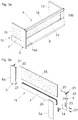
Fig. 4a zeigt das Wandelement 5 mit der von der Schubladenseitenwand 9 abgewandten Anlagefläche 25, an welcher sich der Möbelbeschlag 14 im verbundenen Zustand abstützt. Das Wandelement 5 weist eine Aussparung 23 mit einem Randbereich 23a auf, an welchem sich der Möbelbeschlag 14 zumindest bereichsweise abstützt. Der Möbelbeschlag 14 kann zumindest einen seitlich abstehenden Flügel 28a, 28b aufweisen, welcher sich im verbundenen Zustand am Randbereich 23a der Aussparung 23 abstützt. Der Möbelbeschlag 14 kann mit dem Wandelement 5 zusätzlich noch durch eine Rastverbindung gesichert sein, um ein unbeabsichtigtes Lösen zwischen dem Möbelbeschlag 14 und dem Wandelement 5 zu verhindern. Der wenigstens eine Möbelbeschlag 14 ist ausgehend von der Anlagefläche 25 des Wandelementes 5 zumindest bereichsweise durch die wenigstens eine Aussparung 23 des Wandelementes 5 hindurch führbar. -
Fig. 4b zeigt den in das Wandelement 5 eingeschobenen Möbelbeschlag 14, wobei sich die Flügel 28a, 28b an der Anlagefläche 25 des Wandelementes 5 abstützen. Der Randbereich 23a der Aussparung 23 kann als Vertiefung in Form einer Prägung ausgebildet sein, sodass die Flügel 28a, 28b des Möbelbeschlages 14 mit der Anlagefläche 25 des Wandteiles 5 im Wesentlichen bündig abschließen. Durch ein Abdeckelement 5a (Fig. 4c ), welches über zumindest eine Schnappverbindung 26 am Wandelement 5 fixierbar ist, kann die Aussparung 23 des Wandelementes 5 abgedeckt werden. Der zumindest eine Flügel 28a, 28b des Möbelbeschlages 14 kann im verbundenen Zustand des Möbelbeschlages 14 mit dem Wandelement 5 im Wesentlichen parallel zur Anlagefläche 25 des Wandelementes 5 verlaufen, wodurch sich eine sehr kompakte Konstruktion ergibt und der Möbelbeschlag 14 durch ein flächig ausgebildetes Abdeckelement 5a problemlos abdeckbar ist. -
Fig. 5a zeigt das Wandelement 5 mit dem daran anliegenden Möbelbeschlag 14 in einem Querschnitt. Das Wandelement 5 weist eine in Montagelage zur Schubladenseitenwand 9, 10 hin weisende Befestigungsfläche 24 und eine von der Befestigungsfläche24 abgewandte Anlagefläche 25 auf, wobei sich der Möbelbeschlag 14, vorzugsweise mit zumindest einem Flügel 28b, an der Anlagefläche 25 abstützt. Zu erkennen ist, dass die Anlagefläche 25 des Wandelementes 5 und der Flügel 28b des Möbelbeschlages 14 bündig zueinander verlaufen, sodass zwischen der Anlagefläche 25 und dem Möbelbeschlag 14 keine störende Stoßkante gebildet ist. -
Fig. 5b zeigt eine schematisierte Schublade 4 mit dem Wandelement 5, den Seitenwänden 9, 10 und der Rückwand 12 in einer Draufsicht. In dem inFig. 5b gezeigten Ausführungsbeispiel umgreift der Möbelbeschlag 14 das Wandelement 5 an einem Endbereich, wobei die Anlagefläche 25 des Wandelementes 5 von einer vorderen Sichtfläche des Wandelementes 5 gebildet ist. Im gezeigten Ausführungsbeispiel ist die Anlagefläche 25 des Wandelementes 5 von der Befestigungsfläche 24 des Wandelementes 5 durch eine Materialstärke des Wandelementes 5 beabstandet. Die Möbelbeschläge 14 sind jeweils mit der Verriegelungsvorrichtung 13 der Seitenwände 9, 10 lösbar verriegelbar. -
Fig. 5c zeigt eine weitere Ausführungsform, wobei der Möbelbeschlag 14 in einer seitlichen Ausnehmung des Wandelementes 5 eingreift, wobei die Anlagefläche 25 des Wandelementes 5 von einer Innenseite der Ausnehmung des Wandelementes 5 gebildet ist. - Bei allen Ausführungsformen kann vorgesehen sein, dass die Anlagefläche 25 des Wandelementes 5 im verbundenen Zustand mit der Schubladenseitenwand 9, 10 in Richtung einer Längserstreckung der Schubladenseitenwand 9, 10 von der Befestigungsfläche 24 des Wandelementes 5 beabstandet ist.
Claims (19)
- Schubladenanordnung, umfassend:- eine Schubladenseitenwand (9) mit einer Verriegelungsvorrichtung (13), wobei die Verriegelungsvorrichtung (13) der Schubladenseitenwand (9) einen von zumindest einer Feder (13b) vorgespannten Verriegelungshebel (13a) aufweist,- ein quer mit der Schubladenseitenwand (9) zu verbindendes Wandelement (5), wobei das Wandelement (5) im verbundenen Zustand mit der Schubladenseitenwand (9) eine zur Schubladenseitenwand (9) hin weisende Befestigungsfläche (24) und eine von der Befestigungsfläche (24) abgewandte Anlagefläche (25) aufweist,- wenigstens einen vom Wandelement (5) gesonderten Möbelbeschlag (14) zum Verbinden des Wandelementes (5) mit der Schubladenseitenwand (9), wobei der wenigstens eine Möbelbeschlag (14) mit dem Verriegelungshebel (13a) der Verriegelungsvorrichtung (13) der Schubladenseitenwand (9) lösbar verriegelbar ist,dadurch gekennzeichnet, dass sich der wenigstens eine Möbelbeschlag (14) im verbundenen Zustand des Wandelementes (5) mit der Schubladenseitenwand (9) zumindest bereichsweise an der Anlagefläche (25) des Wandelementes (5) abstützt, sodass das Wandelement (5) durch die Verriegelung des Möbelbeschlages (14) mit der Verriegelungsvorrichtung (13) der Schubladenseitenwand (9) an der Schubladenseitenwand (9) gehalten ist.
- Schubladenanordnung nach Anspruch 1, dadurch gekennzeichnet, dass die Anlagefläche (25) des Wandelementes (5) im verbundenen Zustand mit der Schubladenseitenwand (9) in Richtung einer Längserstreckung der Schubladenseitenwand (9) von der Befestigungsfläche (24) des Wandelementes (5) beabstandet ist.
- Schubladenanordnung nach Anspruch 1 oder 2, dadurch gekennzeichnet, dass die Schubladenseitenwand (9) eine Stirnseite (9a) aufweist, wobei die Befestigungsfläche (24) des Wandelementes (5) im verbundenen Zustand des Wandelementes (5) mit der Schubladenseitenwand (9) zumindest bereichsweise an der Stirnseite (9a) der Schubladenseitenwand (9) anliegt.
- Schubladenanordnung nach einem der Ansprüche 1 bis 3, dadurch gekennzeichnet, dass der Möbelbeschlag (14) im verbundenen Zustand des Wandelementes (5) mit der Schubladenseitenwand (9) an der Anlagefläche (25) des Wandelementes (5) lose anliegt.
- Schubladenanordnung nach einem der Ansprüche 1 bis 4, dadurch gekennzeichnet, dass der Möbelbeschlag (14) zumindest einen seitlich abstehenden Flügel (28a, 28b) aufweist, welcher im verbundenen Zustand des Wandelementes (5) mit der Schubladenseitenwand (9) an der Anlagefläche (25) des Wandelementes (5) anliegt, wobei vorzugsweise vorgesehen ist, dass der zumindest eine Flügel (28a, 28b) im verbundenen Zustand des Möbelbeschlages (14) mit dem Wandelement (5) im Wesentlichen parallel zur Anlagefläche (25) des Wandelementes (5) verläuft.
- Schubladenanordnung nach einem der Ansprüche 1 bis 5, dadurch gekennzeichnet, dass das Wandelement (5) wenigstens eine Aussparung (23) zur Aufnahme des Möbelbeschlages (14) aufweist, wobei der Möbelbeschlag (14) in einem verbundenen Zustand mit dem Wandelement (5) zumindest bereichsweise an einem Randbereich (23a) der Aussparung (23) anliegt und durch die Aussparung (23) des Wandelementes (5) hindurchragt.
- Schubladenanordnung nach Anspruch 6, dadurch gekennzeichnet, dass der wenigstens eine Möbelbeschlag (14) ausgehend von der Anlagefläche (25) des Wandelementes (5) zumindest bereichsweise durch die wenigstens eine Aussparung (23) des Wandelementes (5) hindurch führbar ist.
- Schubladenanordnung nach einem der Ansprüche 1 bis 7, dadurch gekennzeichnet, dass die Schubladenanordnung wenigstens ein Abdeckelement (5a) zur Abdeckung des Wandelementes (5) aufweist, wobei das wenigstens eine Abdeckelement (5a) mit dem Wandelement (5) lösbar verbindbar ist.
- Schubladenanordnung nach Anspruch 8, dadurch gekennzeichnet, dass das Abdeckelement (5a) durch wenigstens eine Schnappverbindung (26) am Wandelement (5) zu befestigen ist.
- Schubladenanordnung nach einem der Ansprüche 1 bis 9, dadurch gekennzeichnet, dass die Schubladenseitenwand (9) einen Aufnahmeraum (29a) zur Aufnahme einer Schubladenausziehführung aufweist.
- Schubladenanordnung nach einem der Ansprüche 1 bis 10, dadurch gekennzeichnet, dass das Wandelement (5) eine Frontblende der Schublade (4) oder ein Teil einer Frontblende der Schublade (4) ist.
- Schubladenwand (11) mit wenigstens einer Schubladenanordnung nach einem der Ansprüche 1 bis 11.
- Schubladenwand nach Anspruch 12, dadurch gekennzeichnet, dass die Schubladenwand (11) ein erstes Wandelement (5) und wenigstens ein zweites Wandelement (6) aufweist, wobei das erste Wandelement (5) durch einen ersten Möbelbeschlag (14) an einer ersten Schubladenseitenwand (9) einer Schublade (4) und dass das zweite Wandelement (6) durch einen zweiten Möbelbeschlag (14) an einer zweiten Schubladenseitenwand (10) der Schublade (4) zu befestigen ist.
- Schubladenwand nach Anspruch 13, dadurch gekennzeichnet, dass das erste Wandelement (5) und das zweite Wandelement (6) durch wenigstens ein Wandprofil (7) miteinander verbunden ist, wobei das erste Wandelement (5) und das zweite Wandelement (6) zusammen mit dem Wandprofil (7) gemeinsam einen Rahmen zur Aufnahme einer Dekorplatte (15) ausbilden, wobei die Dekorplatte (15) in einem montierten Zustand zumindest bereichsweise innerhalb des Rahmens aufgenommen ist.
- Schubladenwand nach Anspruch 14, dadurch gekennzeichnet, dass das erste Wandelement (5) und das zweite Wandelement (6) das Wandprofil (7) jeweils überragen und jeweils zumindest eine Halterung (20) zur Aufnahme eines Endbereiches der Dekorplatte (15) aufweisen.
- Schubladenwand nach Anspruch 14 oder 15, dadurch gekennzeichnet, dass die Dekorplatte (15) aus Glas, Holz, Kunststoff, Metall, Keramik und/oder Stein gebildet ist oder dass die Dekorplatte (15) zumindest bereichsweise eine Textilschicht aufweist.
- Schublade (4) mit wenigstens einer Schubladenanordnung nach einem der Ansprüche 1 bis 11 oder mit zumindest einer Schubladenwand (11) nach einem der Ansprüche 12 bis 16.
- Verfahren zum Verbinden eines Wandelementes (5) an einer Schubladenseitenwand (9) einer Schubladenanordnung nach einem der Ansprüche 1 bis 11, gekennzeichnet durch die folgenden Schritte:- Bereitstellen des vom Wandelement (5) gesonderten Möbelbeschlages (14),- Verbinden des Möbelbeschlages (14) mit dem Wandelement (5), wobei sich der Möbelbeschlag (14) im verbundenen Zustand mit dem Wandelement (5) zumindest bereichsweise an der Anlagefläche (25) des Wandelementes (5) abstützt,- Verbinden des Möbelbeschlages (14) mit der Verriegelungsvorrichtung (13) der Schubladenseitenwand (9), wobei die Befestigungsfläche (24) des Wandelementes (5) im verbundenen Zustand mit der Schubladenseitenwand (9) zur Schubladenseitenwand (9) hin weist.
- Verfahren nach Anspruch 18, dadurch gekennzeichnet, dass der Möbelbeschlag (14) im Zuge des Verbindens des Möbelbeschlages (14) mit dem Wandelement (5) ausgehend von der Anlagefläche (25) des Wandelementes (5) durch die wenigstens eine Aussparung (23) des Wandelementes (5) hindurchgesteckt wird.
Applications Claiming Priority (3)
| Application Number | Priority Date | Filing Date | Title |
|---|---|---|---|
| ATA51063/2017A AT520788B1 (de) | 2017-12-21 | 2017-12-21 | Schubladenanordnung |
| EP18826490.7A EP3727093B1 (de) | 2017-12-21 | 2018-12-13 | Schubladenanordnung |
| PCT/AT2018/060299 WO2019119003A1 (de) | 2017-12-21 | 2018-12-13 | Schubladenanordnung |
Related Parent Applications (1)
| Application Number | Title | Priority Date | Filing Date |
|---|---|---|---|
| EP18826490.7A Division EP3727093B1 (de) | 2017-12-21 | 2018-12-13 | Schubladenanordnung |
Publications (2)
| Publication Number | Publication Date |
|---|---|
| EP3868255A1 true EP3868255A1 (de) | 2021-08-25 |
| EP3868255B1 EP3868255B1 (de) | 2023-03-15 |
Family
ID=64900704
Family Applications (2)
| Application Number | Title | Priority Date | Filing Date |
|---|---|---|---|
| EP18826490.7A Active EP3727093B1 (de) | 2017-12-21 | 2018-12-13 | Schubladenanordnung |
| EP21168099.6A Active EP3868255B1 (de) | 2017-12-21 | 2018-12-13 | Schubladenanordnung |
Family Applications Before (1)
| Application Number | Title | Priority Date | Filing Date |
|---|---|---|---|
| EP18826490.7A Active EP3727093B1 (de) | 2017-12-21 | 2018-12-13 | Schubladenanordnung |
Country Status (9)
| Country | Link |
|---|---|
| US (1) | US11202505B2 (de) |
| EP (2) | EP3727093B1 (de) |
| JP (1) | JP7124087B2 (de) |
| CN (1) | CN111491541A (de) |
| AT (1) | AT520788B1 (de) |
| ES (2) | ES2947519T3 (de) |
| MY (1) | MY200147A (de) |
| TW (1) | TWI679949B (de) |
| WO (1) | WO2019119003A1 (de) |
Families Citing this family (11)
| Publication number | Priority date | Publication date | Assignee | Title |
|---|---|---|---|---|
| AT518790B1 (de) * | 2017-02-21 | 2018-01-15 | Blum Gmbh Julius | Verbindungsstift für Möbelteile |
| USD909107S1 (en) * | 2017-05-09 | 2021-02-02 | Julius Blum Gmbh | Furniture fitting |
| USD909106S1 (en) * | 2017-05-09 | 2021-02-02 | Julius Blum Gmbh | Furniture fitting |
| USD909105S1 (en) * | 2017-05-09 | 2021-02-02 | Julius Blum Gmbh | Furniture fitting |
| AT520636B1 (de) * | 2018-01-26 | 2019-06-15 | Blum Gmbh Julius | Frontblende für eine Schublade |
| AT521512B1 (de) * | 2018-10-05 | 2020-02-15 | Blum Gmbh Julius | Befestigungsvorrichtung zum lösbaren Befestigen einer Frontblende an einer Schublade |
| TWI712381B (zh) * | 2020-02-25 | 2020-12-11 | 川湖科技股份有限公司 | 用於傢俱組件的安裝裝置與安裝方法 |
| TWI843468B (zh) * | 2023-03-06 | 2024-05-21 | 川湖科技股份有限公司 | 傢俱及其傢俱組件 |
| DE102023130066A1 (de) * | 2023-10-31 | 2025-04-30 | Paul Hettich Gmbh & Co. Kg | Schubkasten |
| DE102023130083A1 (de) * | 2023-10-31 | 2025-04-30 | Paul Hettich Gmbh & Co. Kg | Wandelement für einen Schubkasten |
| USD1086758S1 (en) * | 2024-03-27 | 2025-08-05 | Ying Liu | Set of kitchen cabinet drawers |
Citations (7)
| Publication number | Priority date | Publication date | Assignee | Title |
|---|---|---|---|---|
| US4108520A (en) | 1975-09-17 | 1978-08-22 | L. B. (Plastics) Limited | Drawers |
| DE3801103A1 (de) * | 1987-02-04 | 1988-08-18 | Blum Gmbh Julius | Befestigungsvorrichtung fuer einstellbare frontblenden von schubladen |
| EP0740917B1 (de) | 1993-09-21 | 1998-11-25 | Julius Blum Gesellschaft m.b.H. | Vorrichtung zur Befestigung der Frontblende einer Schublade an vorzugsweise doppelwandigen Schubladenzargen |
| WO2007137311A2 (de) * | 2006-05-26 | 2007-12-06 | Julius Blum Gmbh | Schublade mit aufsatzzargen |
| DE202010007427U1 (de) | 2010-05-31 | 2011-09-05 | Grass Gmbh | Verbindungsvorrichtung und Schublade mit einer Verbindungsvorrichtung |
| WO2013029066A1 (de) * | 2011-08-30 | 2013-03-07 | Julius Blum Gmbh | Schublade |
| WO2013067551A1 (de) | 2011-11-11 | 2013-05-16 | Julius Blum Gmbh | Schublade |
Family Cites Families (17)
| Publication number | Priority date | Publication date | Assignee | Title |
|---|---|---|---|---|
| US3773399A (en) * | 1972-03-27 | 1973-11-20 | Whirlpool Co | Front panel construction for refuse compactor drawer |
| DE102006033360A1 (de) * | 2006-07-19 | 2008-01-24 | Lautenschläger, Horst | Bausatz für eine Möbelschublade |
| AT506440B1 (de) * | 2008-03-10 | 2012-10-15 | Blum Gmbh Julius | Schublade mit einer befestigungseinrichtung für wandelemente |
| MX2008006644A (es) * | 2008-05-22 | 2009-11-23 | Mabe Sa De Cv | Sistema de nivelacion para panel o cajon. |
| US8382219B2 (en) * | 2009-05-11 | 2013-02-26 | Sub-Zero, Inc. | Installation system and door positioning device for appliances |
| DE102010037281A1 (de) * | 2010-09-02 | 2012-03-08 | Paul Hettich Gmbh & Co. Kg | Möbelauszugsteil |
| DE202011000300U1 (de) * | 2011-02-10 | 2012-05-15 | Ninkaplast Gmbh | Frontblende für Möbel |
| AT512022A1 (de) * | 2011-09-23 | 2013-04-15 | Blum Gmbh Julius | Möbel |
| AT512236B1 (de) * | 2011-11-22 | 2015-10-15 | Blum Gmbh Julius | Befestigungsvorrichtung zum befestigen einer frontblende an einer schublade |
| ITMI20120985A1 (it) * | 2012-06-06 | 2013-12-07 | Unifor Spa | Struttura di mobile |
| DE102013106092B4 (de) | 2013-06-12 | 2025-07-10 | Paul Hettich Gmbh & Co. Kg | Schubkasten mit Seitenzargen und einer justierbaren Frontblende |
| US9185981B1 (en) * | 2014-08-25 | 2015-11-17 | Richardson Industries, Inc. | Cabinetry system having removable cabinet faces |
| DE202014008003U1 (de) * | 2014-10-02 | 2016-01-05 | Grass Gmbh | Blendenprofilabdeckvorrichtung |
| US9723922B2 (en) * | 2014-11-07 | 2017-08-08 | Hardware Resources, Inc. | Slidable cabinet pullout apparatus and method of use |
| DE202015100068U1 (de) * | 2015-01-09 | 2016-04-13 | Ninkaplast Gmbh | Frontblende für Möbel |
| CN107809927A (zh) * | 2015-06-15 | 2018-03-16 | 形橙产品开发公司 | 具有底板、两个侧壁、后壁以及挡板的抽屉 |
| CN205457295U (zh) * | 2016-01-15 | 2016-08-17 | 广东泰明金属制品有限公司 | 抽屉面板连接装置 |
-
2017
- 2017-12-21 AT ATA51063/2017A patent/AT520788B1/de active
-
2018
- 2018-12-13 ES ES21168099T patent/ES2947519T3/es active Active
- 2018-12-13 EP EP18826490.7A patent/EP3727093B1/de active Active
- 2018-12-13 EP EP21168099.6A patent/EP3868255B1/de active Active
- 2018-12-13 WO PCT/AT2018/060299 patent/WO2019119003A1/de not_active Ceased
- 2018-12-13 ES ES18826490T patent/ES2881618T3/es active Active
- 2018-12-13 CN CN201880081716.5A patent/CN111491541A/zh active Pending
- 2018-12-13 JP JP2020534507A patent/JP7124087B2/ja active Active
- 2018-12-13 MY MYPI2020001150A patent/MY200147A/en unknown
- 2018-12-18 TW TW107145639A patent/TWI679949B/zh active
-
2020
- 2020-05-28 US US16/885,731 patent/US11202505B2/en active Active
Patent Citations (7)
| Publication number | Priority date | Publication date | Assignee | Title |
|---|---|---|---|---|
| US4108520A (en) | 1975-09-17 | 1978-08-22 | L. B. (Plastics) Limited | Drawers |
| DE3801103A1 (de) * | 1987-02-04 | 1988-08-18 | Blum Gmbh Julius | Befestigungsvorrichtung fuer einstellbare frontblenden von schubladen |
| EP0740917B1 (de) | 1993-09-21 | 1998-11-25 | Julius Blum Gesellschaft m.b.H. | Vorrichtung zur Befestigung der Frontblende einer Schublade an vorzugsweise doppelwandigen Schubladenzargen |
| WO2007137311A2 (de) * | 2006-05-26 | 2007-12-06 | Julius Blum Gmbh | Schublade mit aufsatzzargen |
| DE202010007427U1 (de) | 2010-05-31 | 2011-09-05 | Grass Gmbh | Verbindungsvorrichtung und Schublade mit einer Verbindungsvorrichtung |
| WO2013029066A1 (de) * | 2011-08-30 | 2013-03-07 | Julius Blum Gmbh | Schublade |
| WO2013067551A1 (de) | 2011-11-11 | 2013-05-16 | Julius Blum Gmbh | Schublade |
Also Published As
| Publication number | Publication date |
|---|---|
| EP3868255B1 (de) | 2023-03-15 |
| AT520788A1 (de) | 2019-07-15 |
| WO2019119003A1 (de) | 2019-06-27 |
| MY200147A (en) | 2023-12-08 |
| TW201927213A (zh) | 2019-07-16 |
| ES2881618T3 (es) | 2021-11-30 |
| JP7124087B2 (ja) | 2022-08-23 |
| TWI679949B (zh) | 2019-12-21 |
| US20200288865A1 (en) | 2020-09-17 |
| US11202505B2 (en) | 2021-12-21 |
| EP3727093A1 (de) | 2020-10-28 |
| JP2021506499A (ja) | 2021-02-22 |
| ES2947519T3 (es) | 2023-08-10 |
| AT520788B1 (de) | 2023-03-15 |
| EP3727093B1 (de) | 2021-04-21 |
| CN111491541A (zh) | 2020-08-04 |
Similar Documents
| Publication | Publication Date | Title |
|---|---|---|
| EP3727093B1 (de) | Schubladenanordnung | |
| AT510781B1 (de) | Möbelbeschlag zur frontblendenbefestigung | |
| EP2768342B1 (de) | Anordnung mit einer verbindungsvorrichtung zum verbinden zweier rechtwinklig anzuordnender schubladenwandteile | |
| AT520636B1 (de) | Frontblende für eine Schublade | |
| EP3625417B1 (de) | In seiner länge einstellbarer steuerarm | |
| EP4278927B1 (de) | Schublade mit einer haltevorrichtung zur halterung einer auf der schubladenseitenwand aufsetzbaren dekorplatte | |
| AT506440A1 (de) | Schublade mit einer befestigungseinrichtung fur wandelemente | |
| AT515997B1 (de) | Anordnung mit Schubladenseitenwand und Halteteil | |
| AT18053U1 (de) | Relingstrebe für eine Schublade | |
| EP3070344B1 (de) | Anordnung aus möbelbeschlag, befestigungselement und einsatzelement | |
| EP3695748B1 (de) | Einbauschrankanordnung | |
| AT520767B1 (de) | Anordnung aus einem Auflagesteg für einen Schubladenboden und einer Haltevorrichtung | |
| EP1454026B1 (de) | Montageplatte zur verstellbaren halterung von möbelscharnieren am korpus von möbelstücken | |
| AT413583B (de) | Stabilisierungsvorrichtung für möbelteile | |
| EP2020513B1 (de) | Beschlag zum Verbinden zweier Möbelplatten | |
| DE102011015494B4 (de) | Befestigungsanordnung | |
| EP2597997A1 (de) | Verstellelement sowie anordnung eines verstellelementes in einem möbel | |
| DE202016101748U1 (de) | Anschlussverbinder zum Anschluss eines flächigen Elements, insbesondere eines Informations- oder Werbeträgers, an einen Trägerprofilkörper | |
| DE20215892U1 (de) | Feststellvorrichtung für ein bewegliches Bauteil |
Legal Events
| Date | Code | Title | Description |
|---|---|---|---|
| PUAI | Public reference made under article 153(3) epc to a published international application that has entered the european phase |
Free format text: ORIGINAL CODE: 0009012 |
|
| STAA | Information on the status of an ep patent application or granted ep patent |
Free format text: STATUS: THE APPLICATION HAS BEEN PUBLISHED |
|
| AC | Divisional application: reference to earlier application |
Ref document number: 3727093 Country of ref document: EP Kind code of ref document: P |
|
| AK | Designated contracting states |
Kind code of ref document: A1 Designated state(s): AL AT BE BG CH CY CZ DE DK EE ES FI FR GB GR HR HU IE IS IT LI LT LU LV MC MK MT NL NO PL PT RO RS SE SI SK SM TR |
|
| STAA | Information on the status of an ep patent application or granted ep patent |
Free format text: STATUS: REQUEST FOR EXAMINATION WAS MADE |
|
| 17P | Request for examination filed |
Effective date: 20220221 |
|
| RBV | Designated contracting states (corrected) |
Designated state(s): AL AT BE BG CH CY CZ DE DK EE ES FI FR GB GR HR HU IE IS IT LI LT LU LV MC MK MT NL NO PL PT RO RS SE SI SK SM TR |
|
| GRAP | Despatch of communication of intention to grant a patent |
Free format text: ORIGINAL CODE: EPIDOSNIGR1 |
|
| STAA | Information on the status of an ep patent application or granted ep patent |
Free format text: STATUS: GRANT OF PATENT IS INTENDED |
|
| INTG | Intention to grant announced |
Effective date: 20221209 |
|
| GRAS | Grant fee paid |
Free format text: ORIGINAL CODE: EPIDOSNIGR3 |
|
| GRAA | (expected) grant |
Free format text: ORIGINAL CODE: 0009210 |
|
| STAA | Information on the status of an ep patent application or granted ep patent |
Free format text: STATUS: THE PATENT HAS BEEN GRANTED |
|
| AC | Divisional application: reference to earlier application |
Ref document number: 3727093 Country of ref document: EP Kind code of ref document: P |
|
| AK | Designated contracting states |
Kind code of ref document: B1 Designated state(s): AL AT BE BG CH CY CZ DE DK EE ES FI FR GB GR HR HU IE IS IT LI LT LU LV MC MK MT NL NO PL PT RO RS SE SI SK SM TR |
|
| REG | Reference to a national code |
Ref country code: CH Ref legal event code: EP Ref country code: GB Ref legal event code: FG4D Free format text: NOT ENGLISH |
|
| REG | Reference to a national code |
Ref country code: DE Ref legal event code: R096 Ref document number: 502018011795 Country of ref document: DE |
|
| REG | Reference to a national code |
Ref country code: IE Ref legal event code: FG4D Free format text: LANGUAGE OF EP DOCUMENT: GERMAN |
|
| REG | Reference to a national code |
Ref country code: AT Ref legal event code: REF Ref document number: 1553492 Country of ref document: AT Kind code of ref document: T Effective date: 20230415 |
|
| P01 | Opt-out of the competence of the unified patent court (upc) registered |
Effective date: 20230523 |
|
| REG | Reference to a national code |
Ref country code: LT Ref legal event code: MG9D |
|
| REG | Reference to a national code |
Ref country code: NL Ref legal event code: MP Effective date: 20230315 |
|
| PG25 | Lapsed in a contracting state [announced via postgrant information from national office to epo] |
Ref country code: RS Free format text: LAPSE BECAUSE OF FAILURE TO SUBMIT A TRANSLATION OF THE DESCRIPTION OR TO PAY THE FEE WITHIN THE PRESCRIBED TIME-LIMIT Effective date: 20230315 Ref country code: NO Free format text: LAPSE BECAUSE OF FAILURE TO SUBMIT A TRANSLATION OF THE DESCRIPTION OR TO PAY THE FEE WITHIN THE PRESCRIBED TIME-LIMIT Effective date: 20230615 Ref country code: LV Free format text: LAPSE BECAUSE OF FAILURE TO SUBMIT A TRANSLATION OF THE DESCRIPTION OR TO PAY THE FEE WITHIN THE PRESCRIBED TIME-LIMIT Effective date: 20230315 Ref country code: LT Free format text: LAPSE BECAUSE OF FAILURE TO SUBMIT A TRANSLATION OF THE DESCRIPTION OR TO PAY THE FEE WITHIN THE PRESCRIBED TIME-LIMIT Effective date: 20230315 Ref country code: HR Free format text: LAPSE BECAUSE OF FAILURE TO SUBMIT A TRANSLATION OF THE DESCRIPTION OR TO PAY THE FEE WITHIN THE PRESCRIBED TIME-LIMIT Effective date: 20230315 |
|
| REG | Reference to a national code |
Ref country code: ES Ref legal event code: FG2A Ref document number: 2947519 Country of ref document: ES Kind code of ref document: T3 Effective date: 20230810 |
|
| PG25 | Lapsed in a contracting state [announced via postgrant information from national office to epo] |
Ref country code: SE Free format text: LAPSE BECAUSE OF FAILURE TO SUBMIT A TRANSLATION OF THE DESCRIPTION OR TO PAY THE FEE WITHIN THE PRESCRIBED TIME-LIMIT Effective date: 20230315 Ref country code: NL Free format text: LAPSE BECAUSE OF FAILURE TO SUBMIT A TRANSLATION OF THE DESCRIPTION OR TO PAY THE FEE WITHIN THE PRESCRIBED TIME-LIMIT Effective date: 20230315 Ref country code: GR Free format text: LAPSE BECAUSE OF FAILURE TO SUBMIT A TRANSLATION OF THE DESCRIPTION OR TO PAY THE FEE WITHIN THE PRESCRIBED TIME-LIMIT Effective date: 20230616 Ref country code: FI Free format text: LAPSE BECAUSE OF FAILURE TO SUBMIT A TRANSLATION OF THE DESCRIPTION OR TO PAY THE FEE WITHIN THE PRESCRIBED TIME-LIMIT Effective date: 20230315 |
|
| PG25 | Lapsed in a contracting state [announced via postgrant information from national office to epo] |
Ref country code: SM Free format text: LAPSE BECAUSE OF FAILURE TO SUBMIT A TRANSLATION OF THE DESCRIPTION OR TO PAY THE FEE WITHIN THE PRESCRIBED TIME-LIMIT Effective date: 20230315 Ref country code: RO Free format text: LAPSE BECAUSE OF FAILURE TO SUBMIT A TRANSLATION OF THE DESCRIPTION OR TO PAY THE FEE WITHIN THE PRESCRIBED TIME-LIMIT Effective date: 20230315 Ref country code: PT Free format text: LAPSE BECAUSE OF FAILURE TO SUBMIT A TRANSLATION OF THE DESCRIPTION OR TO PAY THE FEE WITHIN THE PRESCRIBED TIME-LIMIT Effective date: 20230717 Ref country code: EE Free format text: LAPSE BECAUSE OF FAILURE TO SUBMIT A TRANSLATION OF THE DESCRIPTION OR TO PAY THE FEE WITHIN THE PRESCRIBED TIME-LIMIT Effective date: 20230315 Ref country code: CZ Free format text: LAPSE BECAUSE OF FAILURE TO SUBMIT A TRANSLATION OF THE DESCRIPTION OR TO PAY THE FEE WITHIN THE PRESCRIBED TIME-LIMIT Effective date: 20230315 |
|
| PG25 | Lapsed in a contracting state [announced via postgrant information from national office to epo] |
Ref country code: SK Free format text: LAPSE BECAUSE OF FAILURE TO SUBMIT A TRANSLATION OF THE DESCRIPTION OR TO PAY THE FEE WITHIN THE PRESCRIBED TIME-LIMIT Effective date: 20230315 Ref country code: PL Free format text: LAPSE BECAUSE OF FAILURE TO SUBMIT A TRANSLATION OF THE DESCRIPTION OR TO PAY THE FEE WITHIN THE PRESCRIBED TIME-LIMIT Effective date: 20230315 Ref country code: IS Free format text: LAPSE BECAUSE OF FAILURE TO SUBMIT A TRANSLATION OF THE DESCRIPTION OR TO PAY THE FEE WITHIN THE PRESCRIBED TIME-LIMIT Effective date: 20230715 |
|
| REG | Reference to a national code |
Ref country code: DE Ref legal event code: R097 Ref document number: 502018011795 Country of ref document: DE |
|
| PLBE | No opposition filed within time limit |
Free format text: ORIGINAL CODE: 0009261 |
|
| STAA | Information on the status of an ep patent application or granted ep patent |
Free format text: STATUS: NO OPPOSITION FILED WITHIN TIME LIMIT |
|
| PG25 | Lapsed in a contracting state [announced via postgrant information from national office to epo] |
Ref country code: SI Free format text: LAPSE BECAUSE OF FAILURE TO SUBMIT A TRANSLATION OF THE DESCRIPTION OR TO PAY THE FEE WITHIN THE PRESCRIBED TIME-LIMIT Effective date: 20230315 Ref country code: DK Free format text: LAPSE BECAUSE OF FAILURE TO SUBMIT A TRANSLATION OF THE DESCRIPTION OR TO PAY THE FEE WITHIN THE PRESCRIBED TIME-LIMIT Effective date: 20230315 |
|
| 26N | No opposition filed |
Effective date: 20231218 |
|
| REG | Reference to a national code |
Ref country code: CH Ref legal event code: PL |
|
| PG25 | Lapsed in a contracting state [announced via postgrant information from national office to epo] |
Ref country code: LU Free format text: LAPSE BECAUSE OF NON-PAYMENT OF DUE FEES Effective date: 20231213 |
|
| PG25 | Lapsed in a contracting state [announced via postgrant information from national office to epo] |
Ref country code: MC Free format text: LAPSE BECAUSE OF FAILURE TO SUBMIT A TRANSLATION OF THE DESCRIPTION OR TO PAY THE FEE WITHIN THE PRESCRIBED TIME-LIMIT Effective date: 20230315 |
|
| GBPC | Gb: european patent ceased through non-payment of renewal fee |
Effective date: 20231213 |
|
| REG | Reference to a national code |
Ref country code: BE Ref legal event code: MM Effective date: 20231231 |
|
| PG25 | Lapsed in a contracting state [announced via postgrant information from national office to epo] |
Ref country code: MC Free format text: LAPSE BECAUSE OF FAILURE TO SUBMIT A TRANSLATION OF THE DESCRIPTION OR TO PAY THE FEE WITHIN THE PRESCRIBED TIME-LIMIT Effective date: 20230315 Ref country code: LU Free format text: LAPSE BECAUSE OF NON-PAYMENT OF DUE FEES Effective date: 20231213 |
|
| REG | Reference to a national code |
Ref country code: IE Ref legal event code: MM4A |
|
| PG25 | Lapsed in a contracting state [announced via postgrant information from national office to epo] |
Ref country code: IE Free format text: LAPSE BECAUSE OF NON-PAYMENT OF DUE FEES Effective date: 20231213 |
|
| PG25 | Lapsed in a contracting state [announced via postgrant information from national office to epo] |
Ref country code: GB Free format text: LAPSE BECAUSE OF NON-PAYMENT OF DUE FEES Effective date: 20231213 |
|
| PG25 | Lapsed in a contracting state [announced via postgrant information from national office to epo] |
Ref country code: BE Free format text: LAPSE BECAUSE OF NON-PAYMENT OF DUE FEES Effective date: 20231231 |
|
| PG25 | Lapsed in a contracting state [announced via postgrant information from national office to epo] |
Ref country code: FR Free format text: LAPSE BECAUSE OF NON-PAYMENT OF DUE FEES Effective date: 20231231 |
|
| PG25 | Lapsed in a contracting state [announced via postgrant information from national office to epo] |
Ref country code: CH Free format text: LAPSE BECAUSE OF NON-PAYMENT OF DUE FEES Effective date: 20231231 |
|
| PG25 | Lapsed in a contracting state [announced via postgrant information from national office to epo] |
Ref country code: IE Free format text: LAPSE BECAUSE OF NON-PAYMENT OF DUE FEES Effective date: 20231213 Ref country code: GB Free format text: LAPSE BECAUSE OF NON-PAYMENT OF DUE FEES Effective date: 20231213 Ref country code: FR Free format text: LAPSE BECAUSE OF NON-PAYMENT OF DUE FEES Effective date: 20231231 Ref country code: CH Free format text: LAPSE BECAUSE OF NON-PAYMENT OF DUE FEES Effective date: 20231231 Ref country code: BE Free format text: LAPSE BECAUSE OF NON-PAYMENT OF DUE FEES Effective date: 20231231 |
|
| PG25 | Lapsed in a contracting state [announced via postgrant information from national office to epo] |
Ref country code: BG Free format text: LAPSE BECAUSE OF FAILURE TO SUBMIT A TRANSLATION OF THE DESCRIPTION OR TO PAY THE FEE WITHIN THE PRESCRIBED TIME-LIMIT Effective date: 20230315 |
|
| PG25 | Lapsed in a contracting state [announced via postgrant information from national office to epo] |
Ref country code: BG Free format text: LAPSE BECAUSE OF FAILURE TO SUBMIT A TRANSLATION OF THE DESCRIPTION OR TO PAY THE FEE WITHIN THE PRESCRIBED TIME-LIMIT Effective date: 20230315 |
|
| PG25 | Lapsed in a contracting state [announced via postgrant information from national office to epo] |
Ref country code: CY Free format text: LAPSE BECAUSE OF FAILURE TO SUBMIT A TRANSLATION OF THE DESCRIPTION OR TO PAY THE FEE WITHIN THE PRESCRIBED TIME-LIMIT; INVALID AB INITIO Effective date: 20181213 |
|
| PG25 | Lapsed in a contracting state [announced via postgrant information from national office to epo] |
Ref country code: HU Free format text: LAPSE BECAUSE OF FAILURE TO SUBMIT A TRANSLATION OF THE DESCRIPTION OR TO PAY THE FEE WITHIN THE PRESCRIBED TIME-LIMIT; INVALID AB INITIO Effective date: 20181213 |
|
| PGFP | Annual fee paid to national office [announced via postgrant information from national office to epo] |
Ref country code: AT Payment date: 20251223 Year of fee payment: 8 |
|
| PGFP | Annual fee paid to national office [announced via postgrant information from national office to epo] |
Ref country code: IT Payment date: 20251218 Year of fee payment: 8 |
|
| PGFP | Annual fee paid to national office [announced via postgrant information from national office to epo] |
Ref country code: TR Payment date: 20251119 Year of fee payment: 8 |
|
| PGFP | Annual fee paid to national office [announced via postgrant information from national office to epo] |
Ref country code: ES Payment date: 20260122 Year of fee payment: 8 |
|
| PGFP | Annual fee paid to national office [announced via postgrant information from national office to epo] |
Ref country code: DE Payment date: 20251229 Year of fee payment: 8 |