EP2769111B1 - Dispositif de commande pour un flux de refroidissement et/ou de lubrification - Google Patents
Dispositif de commande pour un flux de refroidissement et/ou de lubrification Download PDFInfo
- Publication number
- EP2769111B1 EP2769111B1 EP12758484.5A EP12758484A EP2769111B1 EP 2769111 B1 EP2769111 B1 EP 2769111B1 EP 12758484 A EP12758484 A EP 12758484A EP 2769111 B1 EP2769111 B1 EP 2769111B1
- Authority
- EP
- European Patent Office
- Prior art keywords
- valve
- cooling
- oil
- lubricating
- actuator
- Prior art date
- Legal status (The legal status is an assumption and is not a legal conclusion. Google has not performed a legal analysis and makes no representation as to the accuracy of the status listed.)
- Not-in-force
Links
- 238000001816 cooling Methods 0.000 title claims description 94
- 238000005461 lubrication Methods 0.000 title description 7
- 239000003921 oil Substances 0.000 claims description 100
- 239000010687 lubricating oil Substances 0.000 claims description 22
- 230000001050 lubricating effect Effects 0.000 claims description 8
- 230000001276 controlling effect Effects 0.000 claims description 6
- 239000000463 material Substances 0.000 claims description 4
- 230000001105 regulatory effect Effects 0.000 claims description 2
- 230000005540 biological transmission Effects 0.000 description 24
- 238000010586 diagram Methods 0.000 description 4
- 238000013021 overheating Methods 0.000 description 4
- 230000000694 effects Effects 0.000 description 3
- 238000010438 heat treatment Methods 0.000 description 3
- 230000001939 inductive effect Effects 0.000 description 3
- 238000007789 sealing Methods 0.000 description 3
- 241000446313 Lamella Species 0.000 description 2
- 238000002485 combustion reaction Methods 0.000 description 2
- 238000006073 displacement reaction Methods 0.000 description 2
- 238000004804 winding Methods 0.000 description 2
- 230000004913 activation Effects 0.000 description 1
- 230000001154 acute effect Effects 0.000 description 1
- 230000015572 biosynthetic process Effects 0.000 description 1
- 230000009351 contact transmission Effects 0.000 description 1
- 239000002184 metal Substances 0.000 description 1
- 238000000034 method Methods 0.000 description 1
Images


Classifications
-
- F—MECHANICAL ENGINEERING; LIGHTING; HEATING; WEAPONS; BLASTING
- F16—ENGINEERING ELEMENTS AND UNITS; GENERAL MEASURES FOR PRODUCING AND MAINTAINING EFFECTIVE FUNCTIONING OF MACHINES OR INSTALLATIONS; THERMAL INSULATION IN GENERAL
- F16K—VALVES; TAPS; COCKS; ACTUATING-FLOATS; DEVICES FOR VENTING OR AERATING
- F16K31/00—Actuating devices; Operating means; Releasing devices
- F16K31/02—Actuating devices; Operating means; Releasing devices electric; magnetic
-
- F—MECHANICAL ENGINEERING; LIGHTING; HEATING; WEAPONS; BLASTING
- F16—ENGINEERING ELEMENTS AND UNITS; GENERAL MEASURES FOR PRODUCING AND MAINTAINING EFFECTIVE FUNCTIONING OF MACHINES OR INSTALLATIONS; THERMAL INSULATION IN GENERAL
- F16D—COUPLINGS FOR TRANSMITTING ROTATION; CLUTCHES; BRAKES
- F16D25/00—Fluid-actuated clutches
- F16D25/12—Details not specific to one of the before-mentioned types
-
- F—MECHANICAL ENGINEERING; LIGHTING; HEATING; WEAPONS; BLASTING
- F16—ENGINEERING ELEMENTS AND UNITS; GENERAL MEASURES FOR PRODUCING AND MAINTAINING EFFECTIVE FUNCTIONING OF MACHINES OR INSTALLATIONS; THERMAL INSULATION IN GENERAL
- F16D—COUPLINGS FOR TRANSMITTING ROTATION; CLUTCHES; BRAKES
- F16D25/00—Fluid-actuated clutches
- F16D25/12—Details not specific to one of the before-mentioned types
- F16D25/123—Details not specific to one of the before-mentioned types in view of cooling and lubrication
-
- F—MECHANICAL ENGINEERING; LIGHTING; HEATING; WEAPONS; BLASTING
- F16—ENGINEERING ELEMENTS AND UNITS; GENERAL MEASURES FOR PRODUCING AND MAINTAINING EFFECTIVE FUNCTIONING OF MACHINES OR INSTALLATIONS; THERMAL INSULATION IN GENERAL
- F16D—COUPLINGS FOR TRANSMITTING ROTATION; CLUTCHES; BRAKES
- F16D13/00—Friction clutches
- F16D13/58—Details
- F16D13/72—Features relating to cooling
-
- F—MECHANICAL ENGINEERING; LIGHTING; HEATING; WEAPONS; BLASTING
- F16—ENGINEERING ELEMENTS AND UNITS; GENERAL MEASURES FOR PRODUCING AND MAINTAINING EFFECTIVE FUNCTIONING OF MACHINES OR INSTALLATIONS; THERMAL INSULATION IN GENERAL
- F16D—COUPLINGS FOR TRANSMITTING ROTATION; CLUTCHES; BRAKES
- F16D25/00—Fluid-actuated clutches
- F16D25/06—Fluid-actuated clutches in which the fluid actuates a piston incorporated in, i.e. rotating with the clutch
- F16D25/062—Fluid-actuated clutches in which the fluid actuates a piston incorporated in, i.e. rotating with the clutch the clutch having friction surfaces
- F16D25/063—Fluid-actuated clutches in which the fluid actuates a piston incorporated in, i.e. rotating with the clutch the clutch having friction surfaces with clutch members exclusively moving axially
- F16D25/0635—Fluid-actuated clutches in which the fluid actuates a piston incorporated in, i.e. rotating with the clutch the clutch having friction surfaces with clutch members exclusively moving axially with flat friction surfaces, e.g. discs
- F16D25/0638—Fluid-actuated clutches in which the fluid actuates a piston incorporated in, i.e. rotating with the clutch the clutch having friction surfaces with clutch members exclusively moving axially with flat friction surfaces, e.g. discs with more than two discs, e.g. multiple lamellae
-
- F—MECHANICAL ENGINEERING; LIGHTING; HEATING; WEAPONS; BLASTING
- F16—ENGINEERING ELEMENTS AND UNITS; GENERAL MEASURES FOR PRODUCING AND MAINTAINING EFFECTIVE FUNCTIONING OF MACHINES OR INSTALLATIONS; THERMAL INSULATION IN GENERAL
- F16D—COUPLINGS FOR TRANSMITTING ROTATION; CLUTCHES; BRAKES
- F16D25/00—Fluid-actuated clutches
- F16D25/10—Clutch systems with a plurality of fluid-actuated clutches
Definitions
- the invention relates to a device for controlling a cooling and / or lubricating oil flow according to the preamble of claim 1 and the use of the device.
- Lamella switching elements are used in motor vehicle transmissions, in particular automatic transmissions as clutches and brakes for shifting gears.
- the closing and opening is usually done hydraulically, with its own hydraulic circuit is provided with a transmission oil pump.
- a problem with the oil cooling of the fins is that - especially with an open clutch - the cooling oil between the fins leads to an increased drag torque, which loads the circulation of the lubricating oil pump and thus also the transmission efficiency.
- the applicant has become known a cooling oil supply for a wet-running switching element with a disk pack.
- the cooling oil is mechanically, depending on the piston position of the piston of the switching element, z. B. controlled by a piston attached to the sliding plate.
- the switching element is thus continuously applied in the closed state with cooling oil, which is thrown by centrifugal force to the outside against the switching element.
- a cooling oil flow is supplied to the disk pack as required by actuation of a valve.
- the cooling oil supply to the switching element takes place from the outside via an oil passage, wherein the valve is switched on or off demand-oriented.
- US Pat. No. 6,408,621 B1 shows a device according to the preamble of claim 1.
- an electrically controllable valve is provided in a device for controlling a cooling and / or lubricating oil flow, which is non-rotatably connected to the cooling and / or lubrication point, wherein the electrical energy for actuating the valve is supplied without contact.
- the cooling and / or lubrication points - when used in a transmission - lamellar switching elements, in particular clutches, but also be bearings or gears. In multi-plate clutches, drag torques that result when oil supply is not required are reduced.
- the contactless energy transfer is preferably carried out on an inductive basis. As a result, plug connections and friction losses are avoided.
- the valve is at least partially disposed in a function carrier which is rotatably connected to the shaft.
- the cooling and / or lubrication points, preferably multi-plate clutches in a transmission are thus rotatably connected via the function carrier with the shaft, preferably a transmission shaft.
- the valve also referred to below as a cooling oil valve
- the valve is connected on the primary side, ie on its inflow side, via first oil passages in the function carrier and / or in the shaft and via a rotary oil transmitter to a stationary lubricating oil source;
- the oil supply can therefore also be done directly from the rotary oil transfer in the oil channels of the function carrier.
- a plurality of cooling oil valves are arranged on the circumference of the function carrier and a plurality of switching elements on the function carrier, it is advantageous that only one rotary oil transfer, ie only sealed by sealing elements transfer point between the housing and rotating Transmission shaft is provided. This avoids friction and leakage losses.
- the function carrier which has even more functions, that is a multifunction carrier, acts in this case as a valve and ⁇ lverteilgephinuse, in which the oil supplied from the rotary oiler lubricating oil is distributed to a plurality of cooling oil valves in the function carrier.
- the cooling oil valve on the secondary side d. H. assigned on its downstream side second oil channels, which are arranged in the function carrier and have outlet openings in the region of the or the switching elements. From the outlet openings, the oil exits when the valve is open and is replaced by suitable structural means, such. B. baffles and brought by centrifugal force to the one or more disk packs or other cooling and / or lubrication points or thrown off. This achieves effective cooling.
- a radially inwardly directed manifold is arranged in the region of the second oil passages.
- This manifold which has the effect of a siphon, prevents the valve body is idling and is no longer filled with oil.
- the oil is thus after the exit from the valve housing according to the siphon principle initially to a smaller diameter against the centrifugal force - out and then passed to the lamellar switching element. This ensures that the space in which moving parts of the valve are located remains filled with oil, allowing centrifugal force compensation. To compensate for the centrifugal force, it is necessary that the movable valve parts experience sufficient buoyancy by the lubricating oil.
- the valve is designed as a switching or control valve. This makes it possible on the one hand, the valve with the same cooling oil either on or off or to regulate the cooling oil flow in terms of its amount. In case of severe overheating, more cooling oil can thus be supplied, with low heating a lower cooling oil flow is sufficient.
- the valve is part of an actuator, ie the valve or the valve closing member is associated with a servomotor or drive, which causes the opening and closing of the valve.
- the actuator comprises an electric motor which transmits its rotational movement to a valve spindle, which converts the rotational movement into a translational movement of the valve closure member via a thread. This intermediate positions and a relatively high sealing pressure of the valve closure member can be achieved.
- the valve is designed as a solenoid valve. This eliminates a rotational movement in favor of a pure translational movement of a valve lifter. By the solenoid valve a higher dynamics in the valve characteristic is achieved.
- an electronic control unit also referred to below as an electronic module
- the function carrier which is adapted to the function carrier and forms a functional unit with the latter.
- the non-contact transmission of electrical energy and / or signals can be arranged via a primary coil fixed to the housing as well as arranged in the electronic module, d. H. co-rotating secondary coil done.
- the electronics module thus forms a first interface with the stationary part of the energy transmission device and with the electrically controllable actuators a second interface.
- the at least one actuator is at least partially receivable in the electronic control unit.
- These may be parts of the electric drive of the actuator, such as the stator of an electric motor or the magnetic coil of an electromagnet. These parts are enclosed by a housing of the electronic control unit.
- a plurality of valves in the function carrier and in the electronic module are arranged distributed over the circumference.
- the hydraulic circuit which has a higher pressure level, can be connected via its own rotary oil supply to a pressure oil source.
- a shut-off valve With such a shut-off valve, the closing pressure in the closed clutch in Lock cylinder can be maintained without operating the pump.
- Such a shut-off valve is the subject of a simultaneously filed by the Applicant patent application with the internal file reference ZF 003894, which is hereby incorporated in full in the disclosure of the present application.
- movable parts of the actuator so for example, the armature shaft and the valve spindle, which are located in the rotating function carrier, floatingly arranged in the cooling or lubricating oil. This ensures that the moving parts experience a buoyancy, which at least partially compensates the centrifugal force. Thus, the moving parts can be moved even at higher speeds to perform their function without much resistance.
- the average density of the moving parts can be approximated by appropriate measures to the density of the cooling oil.
- the armature shaft can be hollow, resulting in a larger volume and thus a greater buoyancy.
- materials of low density for. As plastic or light metal, the mass of the moving parts and thus the centrifugal force can be reduced.
- a plurality of valves can be connected to a rotary transformer. This reduces the friction losses in the oil supply.
- a temperature sensor for detecting the temperature of the cooling and / or lubricating oil flow is provided, for example in the region of a multi-plate clutch to be cooled or a bearing.
- the desired value can be tracked via the electronic control device.
- the cooling and / or lubricating oil flow is conveyed via a constant pump, that is supplied to the rotary oil exchanger.
- a pump can be used, which is independent of the oil requirement keeps the oil pressure at least approximately constant. This can be z. B. - in motor vehicle transmissions - via a variable displacement pump driven by an internal combustion engine, in which the actual pressure is used for control.
- the at least one cooling and / or lubricating point is designed as a multi-plate clutch.
- the device described above for controlling a cooling and / or lubricating oil flow in a transmission for a motor vehicle, in particular an automatic transmission is used.
- the device described above is due to its compact design, its versatility (multifunctional carrier) and its non-contact energy transfer especially for use in automatic transmissions for motor vehicles, because it improves the efficiency of the transmission.
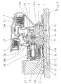
- Fig. 1 shows a device for controlling a flow of cooling oil for an automatic transmission of a motor vehicle.
- a so-called function carrier 2 is rotatably arranged with a rotation axis a.
- a first formed as a multi-plate clutch 3 cooling point and a second formed as a multi-plate clutch 4 cooling point are connected.
- the first multi-plate clutch 3 is actuated via a first annular piston 13
- the second multi-disk clutch 4 is actuated via a second annular piston 14.
- the annular piston 13, 14 are supported on the function carrier 2 plate springs 13a, 14a provided.
- the drive sides of the switching elements 3, 4 are connected via a connecting element 16 and the function carrier 2 with the transmission shaft 1.
- the function carrier 2 is therefore also a carrier of the switching elements 3, 4.
- a so-called rotary oil supply 19, also known as rotary oil transfer 19, provided, ie the cooling oil is passed from a housing-fixed channel 20 in an annular groove 21 in the gear shaft 1. From there, the cooling oil passes through a radial bore 22, an axial bore 23 and a further radial bore 24 in an oil passage 25 of the function carrier 2 and from there into the cooling oil valve 17.
- cooling oil valve 17 acting as a siphon manifold 26, designed as radial inwardly directed pocket 26, arranged in the body 2a of the function carrier 2. From the pocket 26, a dashed oil channel 26a leads to an outlet opening 26b on the outer circumference of the body 2a of the function carrier 2.
- the cooling oil is thus first performed with the cooling oil valve 17 via the pocket 26 radially inwardly and then radially outward. This emptying of the oil space of the cooling oil valve 17 is avoided. This is - as explained below - necessary or advantageous for reasons of centrifugal force compensation by buoyancy.
- the cooling oil passes under the action of centrifugal force and along the slotted plate spring 13a to the lamellar switching element 3, where a demand-based cooling takes place.
- a cooling oil valve 17 is shown.
- a second circumferentially offset cooling oil valve is provided, which is associated with the second lamellae switching element 4, so that the second switching element 4 can be cooled demand-oriented. This is incidentally also from the description Fig. 2 out.
- the cooling oil valve 17 is electrically actuated, in the illustrated embodiment by an electric motor 27, which is arranged in an annularly formed electronic module 28.
- the electronics module 28, which functions as an electronic control unit, is the subject of a separate patent application simultaneously filed by the applicant with the internal file reference ZF 003896. The subject of this simultaneous application is fully incorporated in the disclosure of the present application.
- the cooling oil valve 17 in conjunction with the electric motor 27 forms an actuator, also called an actuator, and has a rotary spindle 17a and a valve closure member 17b connected to it via a movement thread.
- the rotary spindle 17a is connected to a hollow shaft 17c on which an armature of the electric motor 27 not provided with a reference numeral is disposed.
- the rotary spindle 17a and the hollow shaft 17c are subject to a centrifugal force effect at rotating function carrier 2, which can be compensated at least partially by the buoyancy of the lubricating oil and the formation of the valve components in terms of shape and material.
- the electronic module 28, in particular the electric motor 27 receives its electrical energy and its signals for closing and opening the cooling oil valve 17 on an inductive basis: this is on the one hand a housing-side primary coil (without reference numeral) and on the other hand arranged in the electronic module 28 secondary coil 30 (see. Fig. 3 ) arranged. Further details of the electronics module 28 will be described in connection with the description of Fig. 3 explained.
- Fig. 2 shows a section of a lubricating oil circuit diagram for the two lamellar switching elements 3, 4, which are shown symbolically and the switching elements 3, 4 in Fig. 1 correspond.
- the circuit diagram for the lubricating oil corresponds to the circuit diagram for the cooling oil, since the same oil is used for both lubrication and cooling.
- the lubricating or cooling oil is conveyed through a constant pressure pump 33 preferably driven by the internal combustion engine of the motor vehicle and at an approximately constant pressure level of approximately 1.5 bar at the rotary oil transfer 19 (cf. Fig. 1 ) passed to the transmission shaft and thus to the cooling oil valve 17 and another parallel-connected cooling oil valve 31.
- the constant pressure pump 33 is designed as a variable displacement pump, wherein the actual pressure is used for control.
- the cooling oil valves 17, 31 may be designed as switching valves (simple variant) or as control valves, wherein the switching valve, preferably designed as a solenoid valve, only on and connects, ie when an acute cooling demand, eg. B. occurs due to overheating or excessive heating.
- the amount of cooling oil can also be adjusted - depending on the cooling requirement.
- a method of cooling is that the activation of the cooling, ie the opening of the cooling oil valves 17 and / or 31 is particularly desirable when a power dissipation disturbs little or is low.
- a temperature sensor (not shown in the drawing) can be arranged, which detects the oil or component temperature and reports contactlessly to the electronic control unit 28.
- the temperature sensor can be arranged directly on the switching elements 3, 4 and immediately cause an increase in the cooling oil throughput in the event of overheating.
- Fig. 3 shows the electronic module 28, also called electronic control unit 28, as a separate structural unit in a perspective view, wherein two cooling oil valves, the in Fig. 1 illustrated cooling oil valve 17 and another identical cooling oil valve 31 are shown in section.
- the electronic module 28 has an annular housing 39, which is closed by a cover 40 to the outside. Inside the housing, the stator of the electric motor 27 is arranged (same reference numerals as in FIG Fig. 1 used for the same parts). On the housing 39 connecting piece 41 are formed, via which the electronic module 28 to the body 2a of the function carrier 2 (see. Fig. 1 ) is connected. At the same time there is a sealing of the housing 39 relative to the oil space in the body 2a of the function carrier 2 by O-rings 42.
- valves 17, 31 acting as cooling oil valves
- the remaining four valves which are identical, can be used as shut-off valves in a hydraulic circuit, as in the above-mentioned simultaneous application the applicant with the internal file reference ZF 003894 described.
- the rotary spindle 17a and the hollow shaft 17c run in the oil chamber: on the one hand they are subject to a centrifugal force and, on the other hand, experience a buoyancy directed against the centrifugal force, which is determined by the weight of the displaced oil quantity.
- the armature shaft 17c is hollow.
- materials with a low specific weight are preferably used in order to keep the mass and thus the centrifugal force effect low.
- the hollow shaft 17c is mounted twice.
- the electric motor 27 for generating a rotational movement and a magnet in conjunction with a valve lifter may be used in the manner of a solenoid valve.
- the translational movement of the valve stem is then transmitted directly to the closing member.
- the transmission of electrical energy takes place on an inductive basis: for this purpose, a secondary winding 30 is arranged within the electronic module 28 in the radially inner region, which is connected to the primary winding (not shown). Fig. 1 ) is in operative connection.
Landscapes
- Engineering & Computer Science (AREA)
- General Engineering & Computer Science (AREA)
- Mechanical Engineering (AREA)
- General Details Of Gearings (AREA)
- Hydraulic Clutches, Magnetic Clutches, Fluid Clutches, And Fluid Joints (AREA)
Claims (18)
- Procédé de commande d'au moins un flux d'huile réfrigérante et/ou lubrifiante au moyen d'au moins une vanne (17) pour au moins un point de refroidissement et/ou de lubrification (3, 4) relié à un arbre (1), caractérisé en ce que la vanne (17) est commandable électriquement, reliée en rotation solidaire à l'au moins un point de refroidissement et/ou de lubrification (3, 4) et en ce que l'énergie électrique servant à l'actionnement de la vanne (17) peut être acheminée sans contact.
- Dispositif selon la revendication 1, caractérisé en ce que la vanne (17) est disposée, au moins dans certaines zones, dans un support fonctionnel (2) relié en rotation solidaire à l'arbre (1).
- Dispositif selon la revendication 2, caractérisé en ce que le flux d'huile réfrigérante et/ou lubrifiante peut être acheminé à la vanne (17) par le biais de premiers canaux à huile (25, 24, 23) dans le support fonctionnel (2) et/ou dans l'arbre (1) ainsi que par le biais d'un transmetteur d'huile rotatif (19).
- Dispositif selon la revendication 2 ou 3, caractérisé en ce que deux canaux à huile (26, 26a) sont associés à la vanne (17) du côté aval, lesquels sont disposés dans le support fonctionnel (2) et possèdent des ouvertures de sortie (26b) dans la zone de l'au moins un point de refroidissement et/ou de lubrification (3).
- Dispositif selon la revendication 4, caractérisé en ce que les deuxièmes canaux à huile (26a) possèdent un raccord coudé (26) dirigé vers l'intérieur entre la vanne (17) et les ouvertures de sortie (26b).
- Dispositif selon l'une des revendications 1 à 5, caractérisé en ce que la vanne (17) est réalisée sous la forme d'une vanne tout-ou-rien ou de régulation.
- Dispositif selon l'une des revendications 1 à 6, caractérisé en ce que l'au moins une vanne (17) fait partie d'un actionneur et peut être actionnée par le biais d'un moteur électrique (27), d'un arbre d'induit (17c) ainsi que d'une tige de vanne (17a).
- Dispositif selon l'une des revendications 1 à 6, caractérisé en ce que l'au moins une vanne (17) fait partie d'un actionneur et est réalisée sous la forme d'une électrovanne.
- Dispositif selon l'une des revendications 1 à 8, caractérisé en ce qu'un contrôleur électronique (28) peut être fixé au support fonctionnel (2).
- Dispositif selon la revendication 9, caractérisé en ce que l'au moins un actionneur peut être logé au moins partiellement dans le contrôleur électronique (28).
- Dispositif selon l'une des revendications 1 à 10, caractérisé en ce que plusieurs vannes (17) sont disposées dans le support fonctionnel (2) et/ou dans le contrôleur électronique (28) en étant distribuées sur le pourtour.
- Dispositif selon l'une des revendications 2 à 11, caractérisé en ce que les pièces mobiles (17a, 17b, 17c) de l'actionneur sont logées dans le support fonctionnel (2) relié en rotation solidaire à l'au moins un point de refroidissement et/ou de lubrification (3, 4) et sont disposées flottantes dans l'huile réfrigérante.
- Dispositif selon la revendication 12, caractérisé en ce que la densité moyenne des pièces mobiles (17a, 17b, 17c) de l'actionneur est approchée de la densité de l'huile réfrigérante par une sélection des matériaux et/ou une configuration géométrique appropriées.
- Dispositif selon l'une des revendications 3 à 13, caractérisé en ce que le flux d'huile réfrigérante et/ou lubrifiante acheminé par le biais du transmetteur d'huile rotatif (19) peut être acheminé à au moins une vanne supplémentaire (31).
- Dispositif selon l'une des revendications 1 à 14, caractérisé en ce qu'une sonde de température est disposée dans la zone du flux d'huile réfrigérante et/ou lubrifiante.
- Dispositif selon l'une des revendications précédentes, caractérisé en ce que le flux d'huile réfrigérante et/ou lubrifiante peut être refoulé par une pompe à pression constante (33).
- Dispositif selon l'une des revendications 1 à 16, caractérisé en ce que l'au moins un point de refroidissement et/ou de lubrification (3, 4) est réalisé sous la forme d'un élément de commutation à lamelles (3, 4).
- Utilisation d'un dispositif de commande d'un flux d'huile réfrigérante et/ou lubrifiante selon l'une des revendications 1 à 17 dans une boîte de vitesses pour véhicules automobiles.
Applications Claiming Priority (2)
| Application Number | Priority Date | Filing Date | Title |
|---|---|---|---|
| DE102011084584A DE102011084584A1 (de) | 2011-10-17 | 2011-10-17 | Vorrichtung zur Steuerung eines Kühl- und/oder Schmierölstromes |
| PCT/EP2012/067914 WO2013056905A1 (fr) | 2011-10-17 | 2012-09-13 | Dispositif pour commander un flux de refroidissement et/ou d'huile de lubrification |
Publications (2)
| Publication Number | Publication Date |
|---|---|
| EP2769111A1 EP2769111A1 (fr) | 2014-08-27 |
| EP2769111B1 true EP2769111B1 (fr) | 2016-08-17 |
Family
ID=46832411
Family Applications (1)
| Application Number | Title | Priority Date | Filing Date |
|---|---|---|---|
| EP12758484.5A Not-in-force EP2769111B1 (fr) | 2011-10-17 | 2012-09-13 | Dispositif de commande pour un flux de refroidissement et/ou de lubrification |
Country Status (6)
| Country | Link |
|---|---|
| US (1) | US9470329B2 (fr) |
| EP (1) | EP2769111B1 (fr) |
| JP (1) | JP6185475B2 (fr) |
| CN (1) | CN103890434B (fr) |
| DE (1) | DE102011084584A1 (fr) |
| WO (1) | WO2013056905A1 (fr) |
Families Citing this family (10)
| Publication number | Priority date | Publication date | Assignee | Title |
|---|---|---|---|---|
| DE102011084585A1 (de) * | 2011-10-17 | 2013-04-18 | Zf Friedrichshafen Ag | Elektronische Steuereinrichtung zur Steuerung von Aktuatoren |
| DE102012102850A1 (de) | 2012-04-02 | 2013-10-02 | B. Braun Melsungen Ag | Fluidfördervorrichtung und Fluidförderverfahren für medizinische Anwendungen |
| JP5695013B2 (ja) * | 2012-11-02 | 2015-04-01 | 本田技研工業株式会社 | 回転電機の磁石温度推定装置及び磁石温度推定方法 |
| WO2015086009A1 (fr) * | 2013-12-09 | 2015-06-18 | Schaeffler Technologies AG & Co. KG | Système hydraulique pour double embrayage ainsi que procédé de commande ou de refroidissement du double embrayage |
| DE102014209056A1 (de) * | 2014-05-14 | 2015-11-19 | Zf Friedrichshafen Ag | Hybridantriebsanordnung eines Kraftfahrzeuges |
| CN107542569B (zh) * | 2016-06-27 | 2021-05-28 | 舍弗勒技术股份两合公司 | 热管理模块 |
| JP6601382B2 (ja) * | 2016-12-24 | 2019-11-06 | トヨタ自動車株式会社 | 車両用動力伝達装置 |
| JP6509930B2 (ja) * | 2017-03-10 | 2019-05-08 | 本田技研工業株式会社 | 油圧クラッチ装置 |
| SE541048C2 (en) * | 2017-07-07 | 2019-03-19 | Scania Cv Ab | An oil distributor for a lubricating and cooling system in a powertrain |
| DE102019205571A1 (de) * | 2019-04-17 | 2020-10-22 | Zf Friedrichshafen Ag | Kühlölleitelement sowie Antriebsstrang und Hybridmodul mit diesem |
Family Cites Families (22)
| Publication number | Priority date | Publication date | Assignee | Title |
|---|---|---|---|---|
| JPS61112123U (fr) * | 1984-12-25 | 1986-07-16 | ||
| JPH0221337U (fr) * | 1988-07-27 | 1990-02-13 | ||
| JPH08121501A (ja) * | 1994-10-24 | 1996-05-14 | Tochigi Fuji Ind Co Ltd | 変速機 |
| US5613588A (en) * | 1995-02-02 | 1997-03-25 | Clark Equipment Company | Clutch coolant flow control device |
| JPH09112643A (ja) * | 1995-10-17 | 1997-05-02 | Nippon Seiko Kk | トロイダル型無段変速機 |
| US6408621B1 (en) * | 2000-09-11 | 2002-06-25 | Engineered Dynamics Corporation | Fluid coupling assembly |
| DE10150704A1 (de) * | 2001-10-13 | 2003-04-17 | Bayerische Motoren Werke Ag | Lamellenkupplung, insbesondere für Motorräder |
| JP2003172439A (ja) * | 2001-12-10 | 2003-06-20 | Toyota Motor Corp | 潤滑装置 |
| EP1691075B1 (fr) * | 2003-11-14 | 2012-01-11 | Eagle Industry Co., Ltd. | Vanne de commande de capacite |
| US7112156B2 (en) | 2004-02-25 | 2006-09-26 | General Motors Corporation | Transmission with miniature motor for control to oil flow |
| DE102005007685A1 (de) | 2005-02-19 | 2006-08-31 | Zf Friedrichshafen Ag | Kühlölzuführung für ein nasslaufendes Schalt-bzw. Anfahrelement |
| JP5188968B2 (ja) * | 2005-07-29 | 2013-04-24 | ホートン, インコーポレイテッド | 粘性クラッチアセンブリ及び粘性クラッチの運転方法 |
| JP4687540B2 (ja) * | 2006-04-12 | 2011-05-25 | 株式会社デンソー | 流体制御弁 |
| DE102006049275B4 (de) * | 2006-10-19 | 2022-11-17 | Zf Friedrichshafen Ag | Getriebevorrichtung mit mindestens einem über eine wenigstens eine elektrische Komponente aufweisende Aktuatorik betätigbaren Schaltelement |
| EP2122190A1 (fr) | 2006-12-22 | 2009-11-25 | Borgwarner, Inc. | Système de sécurité intégré contre le glissement mécanique pour un embrayage de ventilateur puissant à vitesses multiples |
| ITMI20071071A1 (it) * | 2007-05-25 | 2008-11-26 | Piaggio & C Spa | Dispositivo automatico di comando di un gruppo frizione integrato con un asservimento idraulico per realizzare lo slittamento controllato dei dischi della frizione |
| DE102008000644A1 (de) * | 2008-03-13 | 2009-09-17 | Zf Friedrichshafen Ag | Drehübertragungsanordnung |
| CN102216585B (zh) * | 2008-11-23 | 2014-10-15 | 博格华纳公司 | 带有传感器反馈的风扇传动系统 |
| US20110229323A1 (en) * | 2008-11-23 | 2011-09-22 | Roby Joshua L | Fan drive system with oil pressure control |
| DE102009002261A1 (de) * | 2009-04-07 | 2010-10-14 | Zf Friedrichshafen Ag | Getriebevorrichtung mit wenigstens einem über eine Aktorik betätigbaren Schaltelement |
| JP5875777B2 (ja) * | 2011-03-31 | 2016-03-02 | 株式会社不二工機 | 電動弁 |
| DE102011084583A1 (de) * | 2011-10-17 | 2013-04-18 | Zf Friedrichshafen Ag | Betätigungseinrichtung zum Betätigen von Schaltelementen |
-
2011
- 2011-10-17 DE DE102011084584A patent/DE102011084584A1/de not_active Withdrawn
-
2012
- 2012-09-13 WO PCT/EP2012/067914 patent/WO2013056905A1/fr not_active Ceased
- 2012-09-13 EP EP12758484.5A patent/EP2769111B1/fr not_active Not-in-force
- 2012-09-13 CN CN201280050073.0A patent/CN103890434B/zh not_active Expired - Fee Related
- 2012-09-13 US US14/352,100 patent/US9470329B2/en not_active Expired - Fee Related
- 2012-09-13 JP JP2014534985A patent/JP6185475B2/ja not_active Expired - Fee Related
Also Published As
| Publication number | Publication date |
|---|---|
| EP2769111A1 (fr) | 2014-08-27 |
| US9470329B2 (en) | 2016-10-18 |
| JP2014528561A (ja) | 2014-10-27 |
| CN103890434B (zh) | 2017-04-26 |
| DE102011084584A1 (de) | 2013-04-18 |
| JP6185475B2 (ja) | 2017-08-23 |
| US20140264112A1 (en) | 2014-09-18 |
| WO2013056905A1 (fr) | 2013-04-25 |
| CN103890434A (zh) | 2014-06-25 |
Similar Documents
| Publication | Publication Date | Title |
|---|---|---|
| EP2769111B1 (fr) | Dispositif de commande pour un flux de refroidissement et/ou de lubrification | |
| EP3354920B1 (fr) | Système d'embrayage pour un groupe propulseur et transmission comprenant un tel système d'embrayage | |
| EP1989461B1 (fr) | Dispositif de commutation électromagnétique comportant un moteur linéaire | |
| EP2769110B1 (fr) | Dispositif d'actionnement pour actionner des éléments de commutation | |
| DE102012024699A1 (de) | Kupplungsanordnung mit einer Doppelkupplungseinrichtung | |
| EP1482195B1 (fr) | Dispositif d'accouplement et procédé d'utilisation d'un embrayage multidisques | |
| EP3921562B1 (fr) | Système d'actionnement d'un frein de stationnement | |
| EP1857698B1 (fr) | Agencement d'accouplement | |
| DE102014114590B4 (de) | Hydrauliksteuervorrichtung für Hydraulikdrehmomentwandler | |
| DE102010039171A1 (de) | Kupplung mit schaltbarer Kühlung sowie Verfahren zur Steuerung dieser Kupplung | |
| DE102005027610A1 (de) | Drehmomentübertragungseinrichtung und Antriebsstrang mit dieser | |
| EP2417373B1 (fr) | Boîte de vitesses comportant au moins un élément de changement de vitesse pouvant être actionné par un système d'actionnement | |
| DE102009006422B4 (de) | Doppelkupplungsanordnung für Kraftfahrzeuge und Betätigungsverfahren hierfür | |
| WO2013041409A1 (fr) | Unité embrayage | |
| EP1398520A2 (fr) | Embrayage multidisques | |
| DE202013002494U1 (de) | Automatgetriebe mit verrastbaren Schaltelementen | |
| EP3239549A1 (fr) | Embrayage à friction comprenant un élément intermédiaire | |
| EP0728966A2 (fr) | Soupape de passage / commande pour convertisseurs de couple hydrodynamiques de transmissions automatiques | |
| DE102022130689B3 (de) | Vorrichtung und Verfahren zur Steuerung einer Kupplungseinrichtung | |
| DE102004027113B4 (de) | Nasslaufende Lamellenkupplung mit regelbarer Schmierung und Kühlung | |
| EP1398519B1 (fr) | Embrayage multidisques | |
| DE10337556A1 (de) | Lamellenkupplung | |
| DE102017217722B4 (de) | Kühlmittelsystem zum Kühlen eines Schaltelements | |
| EP4545816A1 (fr) | Embrayage à friction d'une transmission à plusieurs vitesses et entraînement électrique d'un véhicule | |
| DE102013218301A1 (de) | Getriebe mit hydrodynamischem Anfahrelement |
Legal Events
| Date | Code | Title | Description |
|---|---|---|---|
| PUAI | Public reference made under article 153(3) epc to a published international application that has entered the european phase |
Free format text: ORIGINAL CODE: 0009012 |
|
| 17P | Request for examination filed |
Effective date: 20140313 |
|
| AK | Designated contracting states |
Kind code of ref document: A1 Designated state(s): AL AT BE BG CH CY CZ DE DK EE ES FI FR GB GR HR HU IE IS IT LI LT LU LV MC MK MT NL NO PL PT RO RS SE SI SK SM TR |
|
| DAX | Request for extension of the european patent (deleted) | ||
| REG | Reference to a national code |
Ref country code: DE Ref legal event code: R079 Ref document number: 502012007991 Country of ref document: DE Free format text: PREVIOUS MAIN CLASS: F16D0025120000 Ipc: F16K0031020000 |
|
| GRAP | Despatch of communication of intention to grant a patent |
Free format text: ORIGINAL CODE: EPIDOSNIGR1 |
|
| RIC1 | Information provided on ipc code assigned before grant |
Ipc: F16D 25/12 20060101ALI20160303BHEP Ipc: F16D 13/72 20060101ALN20160303BHEP Ipc: F16D 25/10 20060101ALN20160303BHEP Ipc: F16K 31/02 20060101AFI20160303BHEP Ipc: F16D 25/0638 20060101ALN20160303BHEP |
|
| RIC1 | Information provided on ipc code assigned before grant |
Ipc: F16D 25/12 20060101ALI20160309BHEP Ipc: F16K 31/02 20060101AFI20160309BHEP Ipc: F16D 25/10 20060101ALN20160309BHEP Ipc: F16D 25/0638 20060101ALN20160309BHEP Ipc: F16D 13/72 20060101ALN20160309BHEP |
|
| INTG | Intention to grant announced |
Effective date: 20160324 |
|
| GRAS | Grant fee paid |
Free format text: ORIGINAL CODE: EPIDOSNIGR3 |
|
| GRAA | (expected) grant |
Free format text: ORIGINAL CODE: 0009210 |
|
| AK | Designated contracting states |
Kind code of ref document: B1 Designated state(s): AL AT BE BG CH CY CZ DE DK EE ES FI FR GB GR HR HU IE IS IT LI LT LU LV MC MK MT NL NO PL PT RO RS SE SI SK SM TR |
|
| REG | Reference to a national code |
Ref country code: GB Ref legal event code: FG4D Free format text: NOT ENGLISH |
|
| REG | Reference to a national code |
Ref country code: CH Ref legal event code: EP |
|
| REG | Reference to a national code |
Ref country code: IE Ref legal event code: FG4D Free format text: LANGUAGE OF EP DOCUMENT: GERMAN |
|
| REG | Reference to a national code |
Ref country code: AT Ref legal event code: REF Ref document number: 821439 Country of ref document: AT Kind code of ref document: T Effective date: 20160915 |
|
| REG | Reference to a national code |
Ref country code: DE Ref legal event code: R096 Ref document number: 502012007991 Country of ref document: DE |
|
| REG | Reference to a national code |
Ref country code: NL Ref legal event code: MP Effective date: 20160817 |
|
| REG | Reference to a national code |
Ref country code: LT Ref legal event code: MG4D |
|
| PG25 | Lapsed in a contracting state [announced via postgrant information from national office to epo] |
Ref country code: HR Free format text: LAPSE BECAUSE OF FAILURE TO SUBMIT A TRANSLATION OF THE DESCRIPTION OR TO PAY THE FEE WITHIN THE PRESCRIBED TIME-LIMIT Effective date: 20160817 Ref country code: FI Free format text: LAPSE BECAUSE OF FAILURE TO SUBMIT A TRANSLATION OF THE DESCRIPTION OR TO PAY THE FEE WITHIN THE PRESCRIBED TIME-LIMIT Effective date: 20160817 Ref country code: RS Free format text: LAPSE BECAUSE OF FAILURE TO SUBMIT A TRANSLATION OF THE DESCRIPTION OR TO PAY THE FEE WITHIN THE PRESCRIBED TIME-LIMIT Effective date: 20160817 Ref country code: IT Free format text: LAPSE BECAUSE OF FAILURE TO SUBMIT A TRANSLATION OF THE DESCRIPTION OR TO PAY THE FEE WITHIN THE PRESCRIBED TIME-LIMIT Effective date: 20160817 Ref country code: NO Free format text: LAPSE BECAUSE OF FAILURE TO SUBMIT A TRANSLATION OF THE DESCRIPTION OR TO PAY THE FEE WITHIN THE PRESCRIBED TIME-LIMIT Effective date: 20161117 Ref country code: NL Free format text: LAPSE BECAUSE OF FAILURE TO SUBMIT A TRANSLATION OF THE DESCRIPTION OR TO PAY THE FEE WITHIN THE PRESCRIBED TIME-LIMIT Effective date: 20160817 Ref country code: LT Free format text: LAPSE BECAUSE OF FAILURE TO SUBMIT A TRANSLATION OF THE DESCRIPTION OR TO PAY THE FEE WITHIN THE PRESCRIBED TIME-LIMIT Effective date: 20160817 |
|
| PG25 | Lapsed in a contracting state [announced via postgrant information from national office to epo] |
Ref country code: GR Free format text: LAPSE BECAUSE OF FAILURE TO SUBMIT A TRANSLATION OF THE DESCRIPTION OR TO PAY THE FEE WITHIN THE PRESCRIBED TIME-LIMIT Effective date: 20161118 Ref country code: SE Free format text: LAPSE BECAUSE OF FAILURE TO SUBMIT A TRANSLATION OF THE DESCRIPTION OR TO PAY THE FEE WITHIN THE PRESCRIBED TIME-LIMIT Effective date: 20160817 Ref country code: PL Free format text: LAPSE BECAUSE OF FAILURE TO SUBMIT A TRANSLATION OF THE DESCRIPTION OR TO PAY THE FEE WITHIN THE PRESCRIBED TIME-LIMIT Effective date: 20160817 Ref country code: PT Free format text: LAPSE BECAUSE OF FAILURE TO SUBMIT A TRANSLATION OF THE DESCRIPTION OR TO PAY THE FEE WITHIN THE PRESCRIBED TIME-LIMIT Effective date: 20161219 Ref country code: ES Free format text: LAPSE BECAUSE OF FAILURE TO SUBMIT A TRANSLATION OF THE DESCRIPTION OR TO PAY THE FEE WITHIN THE PRESCRIBED TIME-LIMIT Effective date: 20160817 Ref country code: LV Free format text: LAPSE BECAUSE OF FAILURE TO SUBMIT A TRANSLATION OF THE DESCRIPTION OR TO PAY THE FEE WITHIN THE PRESCRIBED TIME-LIMIT Effective date: 20160817 Ref country code: BE Free format text: LAPSE BECAUSE OF NON-PAYMENT OF DUE FEES Effective date: 20160930 |
|
| PG25 | Lapsed in a contracting state [announced via postgrant information from national office to epo] |
Ref country code: RO Free format text: LAPSE BECAUSE OF FAILURE TO SUBMIT A TRANSLATION OF THE DESCRIPTION OR TO PAY THE FEE WITHIN THE PRESCRIBED TIME-LIMIT Effective date: 20160817 Ref country code: EE Free format text: LAPSE BECAUSE OF FAILURE TO SUBMIT A TRANSLATION OF THE DESCRIPTION OR TO PAY THE FEE WITHIN THE PRESCRIBED TIME-LIMIT Effective date: 20160817 |
|
| REG | Reference to a national code |
Ref country code: CH Ref legal event code: PL |
|
| REG | Reference to a national code |
Ref country code: DE Ref legal event code: R097 Ref document number: 502012007991 Country of ref document: DE |
|
| PG25 | Lapsed in a contracting state [announced via postgrant information from national office to epo] |
Ref country code: BG Free format text: LAPSE BECAUSE OF FAILURE TO SUBMIT A TRANSLATION OF THE DESCRIPTION OR TO PAY THE FEE WITHIN THE PRESCRIBED TIME-LIMIT Effective date: 20161117 Ref country code: SK Free format text: LAPSE BECAUSE OF FAILURE TO SUBMIT A TRANSLATION OF THE DESCRIPTION OR TO PAY THE FEE WITHIN THE PRESCRIBED TIME-LIMIT Effective date: 20160817 Ref country code: CZ Free format text: LAPSE BECAUSE OF FAILURE TO SUBMIT A TRANSLATION OF THE DESCRIPTION OR TO PAY THE FEE WITHIN THE PRESCRIBED TIME-LIMIT Effective date: 20160817 Ref country code: SM Free format text: LAPSE BECAUSE OF FAILURE TO SUBMIT A TRANSLATION OF THE DESCRIPTION OR TO PAY THE FEE WITHIN THE PRESCRIBED TIME-LIMIT Effective date: 20160817 Ref country code: DK Free format text: LAPSE BECAUSE OF FAILURE TO SUBMIT A TRANSLATION OF THE DESCRIPTION OR TO PAY THE FEE WITHIN THE PRESCRIBED TIME-LIMIT Effective date: 20160817 |
|
| PLBE | No opposition filed within time limit |
Free format text: ORIGINAL CODE: 0009261 |
|
| STAA | Information on the status of an ep patent application or granted ep patent |
Free format text: STATUS: NO OPPOSITION FILED WITHIN TIME LIMIT |
|
| REG | Reference to a national code |
Ref country code: IE Ref legal event code: MM4A |
|
| PG25 | Lapsed in a contracting state [announced via postgrant information from national office to epo] |
Ref country code: MC Free format text: LAPSE BECAUSE OF FAILURE TO SUBMIT A TRANSLATION OF THE DESCRIPTION OR TO PAY THE FEE WITHIN THE PRESCRIBED TIME-LIMIT Effective date: 20160817 |
|
| REG | Reference to a national code |
Ref country code: FR Ref legal event code: ST Effective date: 20170531 |
|
| 26N | No opposition filed |
Effective date: 20170518 |
|
| GBPC | Gb: european patent ceased through non-payment of renewal fee |
Effective date: 20161117 |
|
| PG25 | Lapsed in a contracting state [announced via postgrant information from national office to epo] |
Ref country code: CH Free format text: LAPSE BECAUSE OF NON-PAYMENT OF DUE FEES Effective date: 20160930 Ref country code: LI Free format text: LAPSE BECAUSE OF NON-PAYMENT OF DUE FEES Effective date: 20160930 Ref country code: FR Free format text: LAPSE BECAUSE OF NON-PAYMENT OF DUE FEES Effective date: 20161017 Ref country code: IE Free format text: LAPSE BECAUSE OF NON-PAYMENT OF DUE FEES Effective date: 20160913 |
|
| PG25 | Lapsed in a contracting state [announced via postgrant information from national office to epo] |
Ref country code: LU Free format text: LAPSE BECAUSE OF NON-PAYMENT OF DUE FEES Effective date: 20160913 Ref country code: SI Free format text: LAPSE BECAUSE OF FAILURE TO SUBMIT A TRANSLATION OF THE DESCRIPTION OR TO PAY THE FEE WITHIN THE PRESCRIBED TIME-LIMIT Effective date: 20160817 |
|
| REG | Reference to a national code |
Ref country code: BE Ref legal event code: MM Effective date: 20160930 |
|
| PG25 | Lapsed in a contracting state [announced via postgrant information from national office to epo] |
Ref country code: GB Free format text: LAPSE BECAUSE OF NON-PAYMENT OF DUE FEES Effective date: 20161117 |
|
| PG25 | Lapsed in a contracting state [announced via postgrant information from national office to epo] |
Ref country code: HU Free format text: LAPSE BECAUSE OF FAILURE TO SUBMIT A TRANSLATION OF THE DESCRIPTION OR TO PAY THE FEE WITHIN THE PRESCRIBED TIME-LIMIT; INVALID AB INITIO Effective date: 20120913 |
|
| PG25 | Lapsed in a contracting state [announced via postgrant information from national office to epo] |
Ref country code: MK Free format text: LAPSE BECAUSE OF FAILURE TO SUBMIT A TRANSLATION OF THE DESCRIPTION OR TO PAY THE FEE WITHIN THE PRESCRIBED TIME-LIMIT Effective date: 20160817 Ref country code: CY Free format text: LAPSE BECAUSE OF FAILURE TO SUBMIT A TRANSLATION OF THE DESCRIPTION OR TO PAY THE FEE WITHIN THE PRESCRIBED TIME-LIMIT Effective date: 20160817 Ref country code: MT Free format text: LAPSE BECAUSE OF FAILURE TO SUBMIT A TRANSLATION OF THE DESCRIPTION OR TO PAY THE FEE WITHIN THE PRESCRIBED TIME-LIMIT Effective date: 20160817 Ref country code: IS Free format text: LAPSE BECAUSE OF FAILURE TO SUBMIT A TRANSLATION OF THE DESCRIPTION OR TO PAY THE FEE WITHIN THE PRESCRIBED TIME-LIMIT Effective date: 20160817 |
|
| PG25 | Lapsed in a contracting state [announced via postgrant information from national office to epo] |
Ref country code: TR Free format text: LAPSE BECAUSE OF FAILURE TO SUBMIT A TRANSLATION OF THE DESCRIPTION OR TO PAY THE FEE WITHIN THE PRESCRIBED TIME-LIMIT Effective date: 20160817 Ref country code: AL Free format text: LAPSE BECAUSE OF FAILURE TO SUBMIT A TRANSLATION OF THE DESCRIPTION OR TO PAY THE FEE WITHIN THE PRESCRIBED TIME-LIMIT Effective date: 20160817 |
|
| REG | Reference to a national code |
Ref country code: AT Ref legal event code: MM01 Ref document number: 821439 Country of ref document: AT Kind code of ref document: T Effective date: 20170913 |
|
| PG25 | Lapsed in a contracting state [announced via postgrant information from national office to epo] |
Ref country code: AT Free format text: LAPSE BECAUSE OF NON-PAYMENT OF DUE FEES Effective date: 20170913 |
|
| PGFP | Annual fee paid to national office [announced via postgrant information from national office to epo] |
Ref country code: DE Payment date: 20200901 Year of fee payment: 9 |
|
| REG | Reference to a national code |
Ref country code: DE Ref legal event code: R119 Ref document number: 502012007991 Country of ref document: DE |
|
| PG25 | Lapsed in a contracting state [announced via postgrant information from national office to epo] |
Ref country code: DE Free format text: LAPSE BECAUSE OF NON-PAYMENT OF DUE FEES Effective date: 20220401 |