EP2772420B1 - Véhicule électrique - Google Patents
Véhicule électrique Download PDFInfo
- Publication number
- EP2772420B1 EP2772420B1 EP12844248.0A EP12844248A EP2772420B1 EP 2772420 B1 EP2772420 B1 EP 2772420B1 EP 12844248 A EP12844248 A EP 12844248A EP 2772420 B1 EP2772420 B1 EP 2772420B1
- Authority
- EP
- European Patent Office
- Prior art keywords
- battery
- vehicle
- receiving portion
- board battery
- board
- Prior art date
- Legal status (The legal status is an assumption and is not a legal conclusion. Google has not performed a legal analysis and makes no representation as to the accuracy of the status listed.)
- Not-in-force
Links
Images



Classifications
-
- B—PERFORMING OPERATIONS; TRANSPORTING
- B60—VEHICLES IN GENERAL
- B60L—PROPULSION OF ELECTRICALLY-PROPELLED VEHICLES; SUPPLYING ELECTRIC POWER FOR AUXILIARY EQUIPMENT OF ELECTRICALLY-PROPELLED VEHICLES; ELECTRODYNAMIC BRAKE SYSTEMS FOR VEHICLES IN GENERAL; MAGNETIC SUSPENSION OR LEVITATION FOR VEHICLES; MONITORING OPERATING VARIABLES OF ELECTRICALLY-PROPELLED VEHICLES; ELECTRIC SAFETY DEVICES FOR ELECTRICALLY-PROPELLED VEHICLES
- B60L1/00—Supplying electric power to auxiliary equipment of vehicles
- B60L1/006—Supplying electric power to auxiliary equipment of vehicles to power outlets
-
- B—PERFORMING OPERATIONS; TRANSPORTING
- B60—VEHICLES IN GENERAL
- B60K—ARRANGEMENT OR MOUNTING OF PROPULSION UNITS OR OF TRANSMISSIONS IN VEHICLES; ARRANGEMENT OR MOUNTING OF PLURAL DIVERSE PRIME-MOVERS IN VEHICLES; AUXILIARY DRIVES FOR VEHICLES; INSTRUMENTATION OR DASHBOARDS FOR VEHICLES; ARRANGEMENTS IN CONNECTION WITH COOLING, AIR INTAKE, GAS EXHAUST OR FUEL SUPPLY OF PROPULSION UNITS IN VEHICLES
- B60K1/00—Arrangement or mounting of electrical propulsion units
- B60K1/04—Arrangement or mounting of electrical propulsion units of the electric storage means for propulsion
-
- B—PERFORMING OPERATIONS; TRANSPORTING
- B60—VEHICLES IN GENERAL
- B60L—PROPULSION OF ELECTRICALLY-PROPELLED VEHICLES; SUPPLYING ELECTRIC POWER FOR AUXILIARY EQUIPMENT OF ELECTRICALLY-PROPELLED VEHICLES; ELECTRODYNAMIC BRAKE SYSTEMS FOR VEHICLES IN GENERAL; MAGNETIC SUSPENSION OR LEVITATION FOR VEHICLES; MONITORING OPERATING VARIABLES OF ELECTRICALLY-PROPELLED VEHICLES; ELECTRIC SAFETY DEVICES FOR ELECTRICALLY-PROPELLED VEHICLES
- B60L50/00—Electric propulsion with power supplied within the vehicle
- B60L50/50—Electric propulsion with power supplied within the vehicle using propulsion power supplied by batteries or fuel cells
- B60L50/60—Electric propulsion with power supplied within the vehicle using propulsion power supplied by batteries or fuel cells using power supplied by batteries
- B60L50/64—Constructional details of batteries specially adapted for electric vehicles
-
- B—PERFORMING OPERATIONS; TRANSPORTING
- B60—VEHICLES IN GENERAL
- B60L—PROPULSION OF ELECTRICALLY-PROPELLED VEHICLES; SUPPLYING ELECTRIC POWER FOR AUXILIARY EQUIPMENT OF ELECTRICALLY-PROPELLED VEHICLES; ELECTRODYNAMIC BRAKE SYSTEMS FOR VEHICLES IN GENERAL; MAGNETIC SUSPENSION OR LEVITATION FOR VEHICLES; MONITORING OPERATING VARIABLES OF ELECTRICALLY-PROPELLED VEHICLES; ELECTRIC SAFETY DEVICES FOR ELECTRICALLY-PROPELLED VEHICLES
- B60L53/00—Methods of charging batteries, specially adapted for electric vehicles; Charging stations or on-board charging equipment therefor; Exchange of energy storage elements in electric vehicles
- B60L53/10—Methods of charging batteries, specially adapted for electric vehicles; Charging stations or on-board charging equipment therefor; Exchange of energy storage elements in electric vehicles characterised by the energy transfer between the charging station and the vehicle
- B60L53/14—Conductive energy transfer
- B60L53/16—Connectors, e.g. plugs or sockets, specially adapted for charging electric vehicles
-
- B—PERFORMING OPERATIONS; TRANSPORTING
- B62—LAND VEHICLES FOR TRAVELLING OTHERWISE THAN ON RAILS
- B62J—CYCLE SADDLES OR SEATS; AUXILIARY DEVICES OR ACCESSORIES SPECIALLY ADAPTED TO CYCLES AND NOT OTHERWISE PROVIDED FOR, e.g. ARTICLE CARRIERS OR CYCLE PROTECTORS
- B62J43/00—Arrangements of batteries
- B62J43/10—Arrangements of batteries for propulsion
- B62J43/16—Arrangements of batteries for propulsion on motorcycles or the like
-
- B—PERFORMING OPERATIONS; TRANSPORTING
- B62—LAND VEHICLES FOR TRAVELLING OTHERWISE THAN ON RAILS
- B62J—CYCLE SADDLES OR SEATS; AUXILIARY DEVICES OR ACCESSORIES SPECIALLY ADAPTED TO CYCLES AND NOT OTHERWISE PROVIDED FOR, e.g. ARTICLE CARRIERS OR CYCLE PROTECTORS
- B62J43/00—Arrangements of batteries
- B62J43/20—Arrangements of batteries characterised by the mounting
- B62J43/28—Arrangements of batteries characterised by the mounting hidden within the cycle frame
-
- B—PERFORMING OPERATIONS; TRANSPORTING
- B62—LAND VEHICLES FOR TRAVELLING OTHERWISE THAN ON RAILS
- B62K—CYCLES; CYCLE FRAMES; CYCLE STEERING DEVICES; RIDER-OPERATED TERMINAL CONTROLS SPECIALLY ADAPTED FOR CYCLES; CYCLE AXLE SUSPENSIONS; CYCLE SIDECARS, FORECARS, OR THE LIKE
- B62K11/00—Motorcycles, engine-assisted cycles or motor scooters with one or two wheels
- B62K11/02—Frames
- B62K11/10—Frames characterised by the engine being over or beside driven rear wheel
-
- H—ELECTRICITY
- H01—ELECTRIC ELEMENTS
- H01M—PROCESSES OR MEANS, e.g. BATTERIES, FOR THE DIRECT CONVERSION OF CHEMICAL ENERGY INTO ELECTRICAL ENERGY
- H01M10/00—Secondary cells; Manufacture thereof
- H01M10/42—Methods or arrangements for servicing or maintenance of secondary cells or secondary half-cells
- H01M10/46—Accumulators structurally combined with charging apparatus
-
- H—ELECTRICITY
- H01—ELECTRIC ELEMENTS
- H01M—PROCESSES OR MEANS, e.g. BATTERIES, FOR THE DIRECT CONVERSION OF CHEMICAL ENERGY INTO ELECTRICAL ENERGY
- H01M50/00—Constructional details or processes of manufacture of the non-active parts of electrochemical cells other than fuel cells, e.g. hybrid cells
- H01M50/20—Mountings; Secondary casings or frames; Racks, modules or packs; Suspension devices; Shock absorbers; Transport or carrying devices; Holders
- H01M50/244—Secondary casings; Racks; Suspension devices; Carrying devices; Holders characterised by their mounting method
-
- H—ELECTRICITY
- H01—ELECTRIC ELEMENTS
- H01M—PROCESSES OR MEANS, e.g. BATTERIES, FOR THE DIRECT CONVERSION OF CHEMICAL ENERGY INTO ELECTRICAL ENERGY
- H01M50/00—Constructional details or processes of manufacture of the non-active parts of electrochemical cells other than fuel cells, e.g. hybrid cells
- H01M50/20—Mountings; Secondary casings or frames; Racks, modules or packs; Suspension devices; Shock absorbers; Transport or carrying devices; Holders
- H01M50/249—Mountings; Secondary casings or frames; Racks, modules or packs; Suspension devices; Shock absorbers; Transport or carrying devices; Holders specially adapted for aircraft or vehicles, e.g. cars or trains
-
- H—ELECTRICITY
- H01—ELECTRIC ELEMENTS
- H01M—PROCESSES OR MEANS, e.g. BATTERIES, FOR THE DIRECT CONVERSION OF CHEMICAL ENERGY INTO ELECTRICAL ENERGY
- H01M50/00—Constructional details or processes of manufacture of the non-active parts of electrochemical cells other than fuel cells, e.g. hybrid cells
- H01M50/20—Mountings; Secondary casings or frames; Racks, modules or packs; Suspension devices; Shock absorbers; Transport or carrying devices; Holders
- H01M50/262—Mountings; Secondary casings or frames; Racks, modules or packs; Suspension devices; Shock absorbers; Transport or carrying devices; Holders with fastening means, e.g. locks
-
- H—ELECTRICITY
- H01—ELECTRIC ELEMENTS
- H01M—PROCESSES OR MEANS, e.g. BATTERIES, FOR THE DIRECT CONVERSION OF CHEMICAL ENERGY INTO ELECTRICAL ENERGY
- H01M50/00—Constructional details or processes of manufacture of the non-active parts of electrochemical cells other than fuel cells, e.g. hybrid cells
- H01M50/20—Mountings; Secondary casings or frames; Racks, modules or packs; Suspension devices; Shock absorbers; Transport or carrying devices; Holders
- H01M50/296—Mountings; Secondary casings or frames; Racks, modules or packs; Suspension devices; Shock absorbers; Transport or carrying devices; Holders characterised by terminals of battery packs
-
- H—ELECTRICITY
- H02—GENERATION; CONVERSION OR DISTRIBUTION OF ELECTRIC POWER
- H02J—ELECTRIC POWER NETWORKS; CIRCUIT ARRANGEMENTS OR SYSTEMS FOR SUPPLYING OR DISTRIBUTING ELECTRIC POWER; SYSTEMS FOR STORING ELECTRIC ENERGY
- H02J7/00—Circuit arrangements for charging or discharging batteries or for supplying loads from batteries
- H02J7/02—Circuit arrangements for charging or discharging batteries or for supplying loads from batteries for charging batteries from AC mains by converters
-
- B—PERFORMING OPERATIONS; TRANSPORTING
- B60—VEHICLES IN GENERAL
- B60K—ARRANGEMENT OR MOUNTING OF PROPULSION UNITS OR OF TRANSMISSIONS IN VEHICLES; ARRANGEMENT OR MOUNTING OF PLURAL DIVERSE PRIME-MOVERS IN VEHICLES; AUXILIARY DRIVES FOR VEHICLES; INSTRUMENTATION OR DASHBOARDS FOR VEHICLES; ARRANGEMENTS IN CONNECTION WITH COOLING, AIR INTAKE, GAS EXHAUST OR FUEL SUPPLY OF PROPULSION UNITS IN VEHICLES
- B60K1/00—Arrangement or mounting of electrical propulsion units
- B60K1/04—Arrangement or mounting of electrical propulsion units of the electric storage means for propulsion
- B60K2001/0405—Arrangement or mounting of electrical propulsion units of the electric storage means for propulsion characterised by their position
- B60K2001/0422—Arrangement under the front seats
-
- B—PERFORMING OPERATIONS; TRANSPORTING
- B60—VEHICLES IN GENERAL
- B60K—ARRANGEMENT OR MOUNTING OF PROPULSION UNITS OR OF TRANSMISSIONS IN VEHICLES; ARRANGEMENT OR MOUNTING OF PLURAL DIVERSE PRIME-MOVERS IN VEHICLES; AUXILIARY DRIVES FOR VEHICLES; INSTRUMENTATION OR DASHBOARDS FOR VEHICLES; ARRANGEMENTS IN CONNECTION WITH COOLING, AIR INTAKE, GAS EXHAUST OR FUEL SUPPLY OF PROPULSION UNITS IN VEHICLES
- B60K1/00—Arrangement or mounting of electrical propulsion units
- B60K1/04—Arrangement or mounting of electrical propulsion units of the electric storage means for propulsion
- B60K2001/0455—Removal or replacement of the energy storages
-
- B—PERFORMING OPERATIONS; TRANSPORTING
- B60—VEHICLES IN GENERAL
- B60K—ARRANGEMENT OR MOUNTING OF PROPULSION UNITS OR OF TRANSMISSIONS IN VEHICLES; ARRANGEMENT OR MOUNTING OF PLURAL DIVERSE PRIME-MOVERS IN VEHICLES; AUXILIARY DRIVES FOR VEHICLES; INSTRUMENTATION OR DASHBOARDS FOR VEHICLES; ARRANGEMENTS IN CONNECTION WITH COOLING, AIR INTAKE, GAS EXHAUST OR FUEL SUPPLY OF PROPULSION UNITS IN VEHICLES
- B60K1/00—Arrangement or mounting of electrical propulsion units
- B60K1/04—Arrangement or mounting of electrical propulsion units of the electric storage means for propulsion
- B60K2001/0455—Removal or replacement of the energy storages
- B60K2001/0466—Removal or replacement of the energy storages from above
-
- B—PERFORMING OPERATIONS; TRANSPORTING
- B60—VEHICLES IN GENERAL
- B60K—ARRANGEMENT OR MOUNTING OF PROPULSION UNITS OR OF TRANSMISSIONS IN VEHICLES; ARRANGEMENT OR MOUNTING OF PLURAL DIVERSE PRIME-MOVERS IN VEHICLES; AUXILIARY DRIVES FOR VEHICLES; INSTRUMENTATION OR DASHBOARDS FOR VEHICLES; ARRANGEMENTS IN CONNECTION WITH COOLING, AIR INTAKE, GAS EXHAUST OR FUEL SUPPLY OF PROPULSION UNITS IN VEHICLES
- B60K7/00—Disposition of motor in, or adjacent to, traction wheel
- B60K2007/0038—Disposition of motor in, or adjacent to, traction wheel the motor moving together with the wheel axle
-
- B—PERFORMING OPERATIONS; TRANSPORTING
- B60—VEHICLES IN GENERAL
- B60K—ARRANGEMENT OR MOUNTING OF PROPULSION UNITS OR OF TRANSMISSIONS IN VEHICLES; ARRANGEMENT OR MOUNTING OF PLURAL DIVERSE PRIME-MOVERS IN VEHICLES; AUXILIARY DRIVES FOR VEHICLES; INSTRUMENTATION OR DASHBOARDS FOR VEHICLES; ARRANGEMENTS IN CONNECTION WITH COOLING, AIR INTAKE, GAS EXHAUST OR FUEL SUPPLY OF PROPULSION UNITS IN VEHICLES
- B60K7/00—Disposition of motor in, or adjacent to, traction wheel
- B60K2007/0092—Disposition of motor in, or adjacent to, traction wheel the motor axle being coaxial to the wheel axle
-
- B—PERFORMING OPERATIONS; TRANSPORTING
- B60—VEHICLES IN GENERAL
- B60K—ARRANGEMENT OR MOUNTING OF PROPULSION UNITS OR OF TRANSMISSIONS IN VEHICLES; ARRANGEMENT OR MOUNTING OF PLURAL DIVERSE PRIME-MOVERS IN VEHICLES; AUXILIARY DRIVES FOR VEHICLES; INSTRUMENTATION OR DASHBOARDS FOR VEHICLES; ARRANGEMENTS IN CONNECTION WITH COOLING, AIR INTAKE, GAS EXHAUST OR FUEL SUPPLY OF PROPULSION UNITS IN VEHICLES
- B60K7/00—Disposition of motor in, or adjacent to, traction wheel
- B60K7/0007—Disposition of motor in, or adjacent to, traction wheel the motor being electric
-
- B—PERFORMING OPERATIONS; TRANSPORTING
- B60—VEHICLES IN GENERAL
- B60L—PROPULSION OF ELECTRICALLY-PROPELLED VEHICLES; SUPPLYING ELECTRIC POWER FOR AUXILIARY EQUIPMENT OF ELECTRICALLY-PROPELLED VEHICLES; ELECTRODYNAMIC BRAKE SYSTEMS FOR VEHICLES IN GENERAL; MAGNETIC SUSPENSION OR LEVITATION FOR VEHICLES; MONITORING OPERATING VARIABLES OF ELECTRICALLY-PROPELLED VEHICLES; ELECTRIC SAFETY DEVICES FOR ELECTRICALLY-PROPELLED VEHICLES
- B60L2200/00—Type of vehicles
- B60L2200/12—Bikes
-
- B—PERFORMING OPERATIONS; TRANSPORTING
- B60—VEHICLES IN GENERAL
- B60Y—INDEXING SCHEME RELATING TO ASPECTS CROSS-CUTTING VEHICLE TECHNOLOGY
- B60Y2200/00—Type of vehicle
- B60Y2200/10—Road Vehicles
- B60Y2200/12—Motorcycles, Trikes; Quads; Scooters
-
- B—PERFORMING OPERATIONS; TRANSPORTING
- B62—LAND VEHICLES FOR TRAVELLING OTHERWISE THAN ON RAILS
- B62K—CYCLES; CYCLE FRAMES; CYCLE STEERING DEVICES; RIDER-OPERATED TERMINAL CONTROLS SPECIALLY ADAPTED FOR CYCLES; CYCLE AXLE SUSPENSIONS; CYCLE SIDECARS, FORECARS, OR THE LIKE
- B62K2204/00—Adaptations for driving cycles by electric motor
-
- H—ELECTRICITY
- H01—ELECTRIC ELEMENTS
- H01M—PROCESSES OR MEANS, e.g. BATTERIES, FOR THE DIRECT CONVERSION OF CHEMICAL ENERGY INTO ELECTRICAL ENERGY
- H01M2220/00—Batteries for particular applications
- H01M2220/20—Batteries in motive systems, e.g. vehicle, ship, plane
-
- H—ELECTRICITY
- H02—GENERATION; CONVERSION OR DISTRIBUTION OF ELECTRIC POWER
- H02J—ELECTRIC POWER NETWORKS; CIRCUIT ARRANGEMENTS OR SYSTEMS FOR SUPPLYING OR DISTRIBUTING ELECTRIC POWER; SYSTEMS FOR STORING ELECTRIC ENERGY
- H02J2207/00—Details of circuit arrangements for charging or discharging batteries or supplying loads from batteries
- H02J2207/20—Charging or discharging characterised by the power electronics converter
-
- Y—GENERAL TAGGING OF NEW TECHNOLOGICAL DEVELOPMENTS; GENERAL TAGGING OF CROSS-SECTIONAL TECHNOLOGIES SPANNING OVER SEVERAL SECTIONS OF THE IPC; TECHNICAL SUBJECTS COVERED BY FORMER USPC CROSS-REFERENCE ART COLLECTIONS [XRACs] AND DIGESTS
- Y02—TECHNOLOGIES OR APPLICATIONS FOR MITIGATION OR ADAPTATION AGAINST CLIMATE CHANGE
- Y02T—CLIMATE CHANGE MITIGATION TECHNOLOGIES RELATED TO TRANSPORTATION
- Y02T10/00—Road transport of goods or passengers
- Y02T10/60—Other road transportation technologies with climate change mitigation effect
- Y02T10/70—Energy storage systems for electromobility, e.g. batteries
-
- Y—GENERAL TAGGING OF NEW TECHNOLOGICAL DEVELOPMENTS; GENERAL TAGGING OF CROSS-SECTIONAL TECHNOLOGIES SPANNING OVER SEVERAL SECTIONS OF THE IPC; TECHNICAL SUBJECTS COVERED BY FORMER USPC CROSS-REFERENCE ART COLLECTIONS [XRACs] AND DIGESTS
- Y02—TECHNOLOGIES OR APPLICATIONS FOR MITIGATION OR ADAPTATION AGAINST CLIMATE CHANGE
- Y02T—CLIMATE CHANGE MITIGATION TECHNOLOGIES RELATED TO TRANSPORTATION
- Y02T10/00—Road transport of goods or passengers
- Y02T10/60—Other road transportation technologies with climate change mitigation effect
- Y02T10/7072—Electromobility specific charging systems or methods for batteries, ultracapacitors, supercapacitors or double-layer capacitors
-
- Y—GENERAL TAGGING OF NEW TECHNOLOGICAL DEVELOPMENTS; GENERAL TAGGING OF CROSS-SECTIONAL TECHNOLOGIES SPANNING OVER SEVERAL SECTIONS OF THE IPC; TECHNICAL SUBJECTS COVERED BY FORMER USPC CROSS-REFERENCE ART COLLECTIONS [XRACs] AND DIGESTS
- Y02—TECHNOLOGIES OR APPLICATIONS FOR MITIGATION OR ADAPTATION AGAINST CLIMATE CHANGE
- Y02T—CLIMATE CHANGE MITIGATION TECHNOLOGIES RELATED TO TRANSPORTATION
- Y02T90/00—Enabling technologies or technologies with a potential or indirect contribution to GHG emissions mitigation
- Y02T90/10—Technologies relating to charging of electric vehicles
- Y02T90/14—Plug-in electric vehicles
Definitions
- the present invention relates to an improvement in an electric vehicle driven to travel by an electric power of an on-board battery.
- a power assisted bicycle includes a battery housing device disposed along a rear surface of a seat tube supporting a seat.
- the battery housing device has an outer box providing a visual appearance of the device.
- an inner box incorporating a battery therein is releasably housed in the outer box.
- a connection mechanism mates with female terminals to electrically connect the battery to a vehicle-body-side such that electric energy generated by an on-board electric generator is supplied through the connection mechanism to the battery to supply vehicle-body-side parts (an electric motor and on-board electrical components etc.) with an electric power stored in the battery.
- An external plug can be inserted into a charge opening of the battery housing device, as needed, to allow an external power supply to charge the battery.
- the on-board battery is mounted on the vehicle body for the purpose of supplying an electric power to vehicle-body-side parts (an electric motor and electrical components). Apart from supply of a bit of electrical power to the electrical components, however, the on-board battery is not effectively used as the electric vehicle does not travel.
- JP 2011 136626 (on which the pre-characterising part of claim 1 is based) to provide an electric vehicle including a vehicle body, an on-board battery mounted on the vehicle body, and an electric motor supplied with electric power from the on-board battery, the electric vehicle being driven by the electric motor to travel, wherein the vehicle body includes a battery receiving portion for releasably receiving the on-board battery, the battery receiving portion having vehicle-body-side feeding terminals disposed on a bottom thereof for supplying electric power of the on-board battery to a vehicle body side, wherein the on-board battery has battery-side feeding terminals disposed on a bottom surface thereof for mating with the vehicle-body-side feeding terminals of the battery receiving portion, and wherein the on-board battery has a charge portion disposed on one lateral surface thereof for allowing an external power supply to charge the on-board battery, the one lateral surface facing one of left and right sides of the vehicle body.
- the on-board battery which is a high-quality electrical storage device, is expected to be utilized as the electric vehicle does not travel.
- It is an object of the present invention is to provide an electric vehicle including an on-board battery having an extended utility.
- the present invention is characterised in that the on-board battery has a discharge portion disposed on an opposite lateral surface for supplying electric power of the on-board battery to an outside, the opposite lateral surface facing the other of the left and right sides of the vehicle body, and wherein the on-board battery has a transformer incorporated therein for transforming electric power and/or converting DC to AC, and wherein the vehicle body includes lateral surfaces having a charge side opening for allowing a plug or a connector to pass through the charge side opening into connection to the charge portion, and a discharge side opening for allowing a plug or a connector to pass through the discharge side opening into connection to the discharge portion.
- the on-board battery has a raised or recessed portion formed on a surface thereof, and the battery receiving portion has a recessed or raised guide for guiding the raised or recessed portion of the on-board battery.
- the battery receiving portion is provided with a locking mechanism for preventing the on-board battery received in the battery receiving portion from coming out of the battery receiving portion.
- the vehicle-body-side feeding terminals protrude upwardly from the bottom of the battery receiving portion.
- the charge side opening and the discharge side opening are closed by lids each movable between an open position and a closed position.
- the vehicle body further includes a receptacle disposed behind the battery receiving portion and the receptacle receives an operational lever of the locking mechanism.
- the bottom of the battery receiving portion has a drainage port formed therethrough.
- the on-board battery has the transformer incorporated therein for transforming the electric power and/or converting the DC to the AC.
- the charge portion is disposed for allowing the external power supply to charge the on-board battery.
- the discharge portion is disposed for supplying an electric power of the on-board battery to the outside.
- the discharge portion can be connected to a plug or connector of an electrical product to make the product available as the electric vehicle does not travel.
- the charge portion can be supplied with an electric power from the external power supply, and the electric power is transformed by the transformer and supplied through the discharge portion to the electric product. That is, the discharge can be done during the charge.
- the on-board battery drives the electric motor as the vehicle travels, and supplies the electric power to the electric product as the vehicle does not travel.
- the on-board battery is always available.
- the electric vehicle including the on-board battery having the extended utility.
- the on-board battery has the raised or recessed portion formed on the surface thereof, and the battery receiving portion has the recessed or raised guide.
- the raised (or recessed) portion of the on-board battery can be guided by the recessed (or raised) guide of the battery receiving portion such that the on-board battery can be smoothly released from and inserted into the battery receiving portion without shaking.
- the on-board battery can be more accurately positioned in the battery receiving portion to allow the battery-side feeding terminals to smoothly mate with the vehicle-body-side feeding terminals.
- the battery receiving portion is provided with the locking mechanism for preventing the received on-board battery from coming out of the battery receiving portion.
- the locking mechanism locks the on-board battery in the battery receiving portion, such that the on-board battery is not likely to be displaced upwardly out of the battery receiving portion even when the vehicle shakes up and down on a bumpy road. That is, the on-board battery can be surely fixed by the locking mechanism.
- the vehicle-body-side feeding terminals protrude upwardly from the bottom of the battery receiving portion. Water may intrude into the battery receiving portion through a chink in the battery. Even if water is collected on the bottom of the battery receiving portion, the vehicle-body-side feeding terminals, which are located above the bottom of the battery receiving portion, are not submerged in the collected water.
- the on-board battery has a recess formed on the bottom surface thereof to conform to the upward protrusion of the vehicle-body-side feeding terminals, and the battery-side feeding terminals are disposed in this recess.
- the recess can receive and guide the vehicle-body-side feeding terminals to more accurately position the on-board battery and hence facilitate mounting of the on-board battery.
- the charge side opening and the discharge side opening are closed by the lids movable between the opened position and the closed position.
- the charge side opening and the discharge side opening may be subjected to intrusion of rainwater or dust if these openings were kept open or exposed.
- the lids are provided for preventing the intrusion of the rainwater or dust into the openings.
- the vehicle body further includes the receptacle disposed behind the battery receiving portion, and the receptacle receives the operational lever of the locking mechanism.
- the receptacle defines a space available to allow an operator to put his hand into the space for manipulating the operational lever.
- the manipulation of the operational lever easily controls the locking mechanism.
- the bottom of the battery receiving portion has the drainage port formed therethrough.
- the drainage port can discharge water as soon as the water intrudes into the battery receiving portion. As a result, it is becomes possible to prevent the battery from being deteriorated by the submersion of the battery in the water.
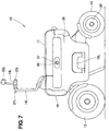
- an electric vehicle 10 includes a box-shaped vehicle body 11 having front and rear wheels 12, 13.
- a headlight 14, a left front blinker 15L and a right front blinker 15R are disposed on a front surface of the vehicle body 11.
- the vehicle body 11 includes handle posts 16L, 16R at a front portion of a top surface thereof.
- the vehicle 11 includes a sear 17 disposed on a rear portion of the top surface thereof.
- the vehicle body 11 further includes pivotable steps 18L, 18R at opposite lateral sides thereof.
- the electric vehicle 10 is an electric motorcycle adapted to be driven by an electric motor 20 incorporated in the rear wheel 13.
- the left step 18L is shown as being upright (a non-used and stowed position) and the right step 18R is shown as lying (a used position).
- a rider sits on the seat 17 with his feet on the steps 18L,18R, gripping both a handle grip 19L on a top of the left handle post 16L and a right handle grip 19R on a top of the right handle post 16R. Then, he rides on the electric vehicle 10 by turning the right handle grip 19R. During his riding, he can apply a brake to the electric vehicle 10 by left and right brake levers 21L, 21R, and look behind by left and right rearview mirrors 22L, 22R. Position lamps are provided at lateral outer ends of the handle grips 19L, 19R to indicate a width of the vehicle to the surroundings.
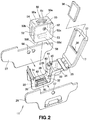
- Fig. 2 is an exploded perspective view of the relevant part of the vehicle body 11.
- the vehicle body 11 primarily includes a central frame 25 disposed laterally centrally thereof, a left side frame 26 disposed along a left side surface of the central frame 25, and a right side frame 27 disposed along a right side surface of the central frame 25.
- the central frame 25 includes a front wall 31, a bottom 32, a rear wall 33, and a receptacle 34 disposed behind and contiguous with the rear wall 33.
- the front wall 31, the bottom 32 and the rear wall 33 define a battery receiving portion 28.
- the seat 17 is attached through a hinge 35 to a rear portion of the receptacle 34 in such a manner as to move between an open position and a closed position.
- the seat 17 has a pocket portion 37 formed on a bottom (lower surface) thereof to releasably receive a tablet terminal 36.
- the pocket portion 37 has a terminal part 38 at one end thereof for electrical connection of the tablet terminal 36 to a vehicle body side.
- the tablet terminal 36 serves as an on-board computer while the electric vehicle 10 travels, as is discussed in detail later.
- the seat 17 can move to the open position, as shown in Fig. 2 , to set the tablet terminal 36 uprightly to display an enjoyable video or game like a television set, as well as to act as a personal computer providing an information tool via an internet.
- the battery receiving portion 28 has a plurality of foot-receiving recesses 39 formed on the bottom 32. These recesses 39 are connected to one another via communication grooves 41. The recesses 39 surround an area where vehicle-body-side feeding terminals 42 are to be positioned.
- the rear wall 33 has a vertically elongated recessed guide 43 formed thereon. Although not shown, a recessed guide is formed on the front wall 31.
- a locking mechanism 44 is mounted on the rear wall 33. As is discussed in detail later, the locking mechanism 44 has an operational lever 45 extending into the receptacle 34.
- the operational lever 45 is preferably located closer to a right or left end of the receptacle 34, such that the operational lever 45 does not get in the way of putting small goods into or out of the receptacle 34.
- An on-board battery 50 is a relatively simple hexahedron having a top surface 50a with a handle 51, front and rear surfaces 50b, 50c having vertically elongated raised portion 52, 52, a left side surface 50d having a charge portion 53, a right side surface 50e having discharge portions 54, 55, and a bottom surface 50f having battery-side feeding terminals 56.
- the on-board battery 50 can be lowered with the raised portions 52, 52 fitting in the recessed guides of the front and rear walls 31, 33, such that the on-board battery 50 can be smoothly received in the battery receiving portion 28. Since the raised portions 52, 52 fit in the recessed guides during the lowering of the on-board battery 50, the battery-side feeding terminals 56 can come into mating engagement with the vehicle-body-side feeding terminals 42 without shaking. In addition, the raised portions 52, 52 fit in the recessed guides to allow the on-board battery 50 to be released upwardly out of the battery receiving portion 28 without shaking.
- the raised portions 52, 52 may be changed into recessed portions, in which case the recessed guides are changed into raised guides.
- the left side frame 26 has a charge side opening 57 at a location corresponding to the charge portion 53 of the on-board battery 50.
- the right side frame 27 has discharge side openings 58, 58 at locations corresponding to the discharge portions 54, 55 of the on-board battery 50.
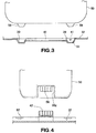
- the on-board battery 50 has a plurality of feet 59 protruding from the bottom surface 50f to allow for positioning only the on-board battery 50 on a floor or road.
- the foot-receiving recesses 39 on the bottom 32 are configured to receive those feet 59.
- the recesses 39 are connected to one another through the communication grooves 41.
- One of the four recesses 39 has a drainage port 61 formed therethrough.
- Water collected in the other foot-receiving recesses 39 passes through the communication grooves 41 into the one foot-receiving recess 39 and discharged through the drainage port 61 out of the vehicle body.
- the one of the four foot-receiving recesses 39 has the drainage port 61 to reduce likelihood of flow of water back into the battery receiving portion 28.
- the on-board battery 50 has a recess 50g corresponding to the vehicle-body-side feeding terminals 42, and the battery-side feeding terminals 56 are disposed in the recess 50g.
- the recess 50g has a depth set to conform to the upward protrusion of the vehicle-body-side feeding terminals 42, such that the recess 50g acts as a guide to accurately position the battery-side feeding terminals 56 relative to the vehicle-body-side feeding terminals 56 so as to bring the battery-side-feeding terminals 56 into mating engagement with the vehicle-body-side feeding terminals 42.
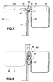
- the locking mechanism 44 includes a stopper projection 65 pivotably attached to an upper portion of the rear wall 33 through a pin 64.
- the operational lever 45 of the locking mechanism 44 extends from the stopper projection 65 and provides a tab portion for engagement with an operator's finger.
- the locking mechanism 44 further includes a torsion spring 66 urging the stopper projection 65 against the top surface of the on-board battery 50.
- the operational lever 45 extends into the receptacle 34.
- a temporary stopper 67 is rotatably disposed on the receptacle 34 for temporarily retaining the operational lever 45.
- the operational lever 45 is depressed to cause the stopper projection 65 to pivot away from the on-board battery 50, after which the depressed operational lever 45 is retained by the temporary stopper 67.
- the on-board battery 50 can be inserted into the battery receiving portion 28 with the depressed operational lever 45 retained by the temporary stopper 67.
- the temporary stopper 67 is rotated to free the operational lever 45, such that the stopper projection 65 is forced to pivot back onto the top surface 50a of the on-board battery 50, as shown in Fig. 5 , so as to hold down the top surface 50a.
- a lid on the charge side opening 57 of the left side frame 26 in such a manner that the charge side opening 57 is opened or closed by the lid.
- a lid Two examples of such a lid, i.e., a shutter and a plug are discussed below in order.
- Fig. 8(a) is an enlarged view of the relevant portion of Fig. 7 .
- Fig. 8(b) is a rear elevation view of the relevant portion shown in Fig. 7 .
- two L-shaped cross-sectional rails 68, 68 bare attached to a back surface of the left side frame 26 (i.e., a surface facing a center of the vehicle body).
- a shutter 69 fits between the two rails 68, 68 and is urged by a compression spring 71 to a closed position.
- a stopper pin 72 for stopping the shutter 69 in the closed position is disposed in protrusion from the left side frame 26.
- Fig. 8(c) illustrating a function of the shutter 69 shown in Fig. 8(a)
- the shutter 69 is moved to an open position with an operator's finger engaging a tab 73.
- the charge side opening 57 is opened to reveal the charge portion 53 behind the charge side opening 57.
- a feeding plug 74 (or a feeding connector) is inserted into the charge portion 53 to charge the on-board battery.
- the shutter 69 is forced to move back to the closed position under the action of the compression spring 71, such that the charge side opening 57 is closed by the shutter 69, as shown in Fig. 8(a) .
- plugs 76, 76 of rubber or soft resin fit in or cover the discharge side openings 58, 58.
- FIG. 10(b) removal of the plug 76 reveals the discharge portion 54 (or 55) behind the discharge side opening.
- a receiving plug 75 (or a receiving connector) of an electrical product is connected to the discharge portion 54.
- the plug 76 is desirably connected to the right side frame 27 by means of a string-like part 77 such as a chain so as to prevent loss of the plug 76.
- All of the charge side opening 57 and the discharge side openings 58, 58 may be closed by the plugs 76.
- the plug 76 is of simple structure and cheap. It is noted that the string-like part 77 may get in the way or the plug 76 partially protrudes from the frame 27. In light of these factors, it is preferable to close all of the charge side opening 57 and the discharge side openings 58, 58 by the shutters 69.
- the lid may be the plug 76, the shutter 69 or other similar closing members regardless of the kind and type.
- Fig. 11 is a rear perspective view of the electric vehicle 10.
- the electric vehicle 10 includes a mobile terminal 80 between the left and right handle posts 16L, 16R.
- the mobile terminal 80 includes a display portion 81 for displaying a vehicle velocity, a directional indication, an amount of electric power stored in the battery, and other statuses.
- the mobile terminal 80 further includes a terminal body 82 incorporating therein an arithmetic circuit and a memory. That is, the electric vehicle 10 does not have a fixed meter unit, and the mobile terminal 80 serves as a meter unit.
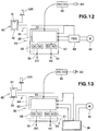
- the on-board battery 50 includes a battery case 84, a battery body 85 disposed in the battery case 84, and transformers 86, 87 disposed in the battery case 84.
- the transformer 86 is a DC/DC converter for a DC voltage to a different DC voltage.
- the transformer 87 is, for example, a DC/AC inverter for converting DC 12 V into AC 100 V.
- a given DC e.g., DC 24 V
- a commercial power supply AC 100 V, 110 V, 200 V, 220 V etc.
- a battery charger 88 to the charge portion 53 for charging the on-board battery.
- the on-board battery 50 serves as a power supply in, e.g., an outdoor camp as the electric vehicle does not travel. That is, AC 100 V (or AC 110 V) can be supplied from the discharge portion 54 to a rice steamer or lighting.
- DC 12 V can be supplied from the discharge portion 55 to a personal computer.
- the on-board battery 50 can be supplied with an electric power not only as the on-board battery 50 is mounted on the vehicle body but also as the on-board battery 50 is detached from the vehicle body, that is, the on-board battery 50 is provided solo.
- a feed line "a" shown by a phantom line extends from the transformer 86 and is electrically connected to the mobile terminal 80 for supplying the mobile terminal 80 with an electric power constantly or as needed. As a result, it becomes possible to prevent reduction in electric power remaining in a battery incorporated in the mobile terminal 80.
- Fig. 13 is a view showing an alternative to an arrangement shown in Fig. 12 . More specifically, in Fig. 13 , the tablet terminal 36 is provided in place of the drive circuit 89. Fig. 13 shows the same elements as those in Fig. 13 except for the tablet terminal 36, and hence discussions of the elements are omitted.
- a feed line "b" shown by a phantom line extends from the transformer 87 and is electrically connected to the tablet terminal 36 for supplying the tablet terminal 36 with an electric power constantly or as needed. As a result, it becomes possible to prevent reduction in electric power remaining in a battery incorporated in the tablet terminal 36.
Landscapes
- Engineering & Computer Science (AREA)
- Mechanical Engineering (AREA)
- Chemical & Material Sciences (AREA)
- Power Engineering (AREA)
- Electrochemistry (AREA)
- General Chemical & Material Sciences (AREA)
- Chemical Kinetics & Catalysis (AREA)
- Transportation (AREA)
- Manufacturing & Machinery (AREA)
- Combustion & Propulsion (AREA)
- Sustainable Development (AREA)
- Life Sciences & Earth Sciences (AREA)
- Sustainable Energy (AREA)
- Aviation & Aerospace Engineering (AREA)
- Electric Propulsion And Braking For Vehicles (AREA)
- Arrangement Or Mounting Of Propulsion Units For Vehicles (AREA)
- Battery Mounting, Suspending (AREA)
- Charge And Discharge Circuits For Batteries Or The Like (AREA)
- Secondary Cells (AREA)
Claims (7)
- Véhicule électrique (10) incluant une carrosserie de véhicule (11), une batterie embarquée (50) montée sur la carrosserie de véhicule, et un moteur électrique (20) alimenté en énergie électrique provenant de la batterie embarquée, le véhicule électrique étant entraîné par le moteur électrique pour se déplacer,
dans lequel la carrosserie de véhicule inclut une partie de réception de batterie (28) pour recevoir de façon amovible la batterie embarquée, la partie de réception de batterie ayant des bornes d'alimentation (42) côté carrosserie de véhicule disposées sur un fond (32) de celle-ci pour fournir de l'énergie électrique de la batterie embarquée à un côté carrosserie de véhicule,
dans lequel la batterie embarquée a des bornes d'alimentation (56) côté batterie disposées sur une surface de fond (50f) de celle-ci pour s'accoupler avec les bornes d'alimentation côté carrosserie de véhicule de la partie de réception de batterie, et dans lequel la batterie embarquée a une partie de charge (53) disposée sur une surface latérale (50d) de celle-ci pour permettre à une alimentation en énergie externe de charger la batterie embarquée, la surface latérale particulière faisant face à un des côtés de gauche et de droite de la carrosserie de véhicule, caractérisé en ce que la batterie embarquée a une partie de décharge (54 ; 55) disposée sur une surface latérale opposée (50e) pour fournir une énergie électrique de la batterie embarquée à un extérieur, la surface latérale opposée faisant face à l'autre des côtés de gauche et de droite de la carrosserie de véhicule, et dans lequel la batterie embarquée a un transformateur (86 ; 87) incorporé en son sein pour transformer l'énergie électrique et/ou transformer le courant continu CC en courant alternatif CA, et
dans lequel la carrosserie de véhicule inclut des surfaces latérales ayant une ouverture côté charge (57) pour permettre à une prise (74) ou à un connecteur de passer à travers l'ouverture côté charge en connexion avec la partie de charge, et une ouverture côté décharge (58) pour permettre à une prise (75) ou à un connecteur de passer à travers l'ouverture côté décharge en connexion avec la partie de décharge. - Véhicule selon la revendication 1, dans lequel la batterie embarquée a une partie élevée ou enfoncée formée sur une surface de celle-ci, et la partie de réception de batterie a un guide enfoncé ou élevé pour guider la partie élevée ou enfoncée de la batterie embarquée.
- Véhicule selon la revendication 1 ou 2, dans lequel la partie de réception de batterie est munie d'un mécanisme de verrouillage pour empêcher la batterie embarquée reçue dans la partie de réception de batterie de sortir de la partie de réception de batterie.
- Véhicule selon la revendication 1, dans lequel les bornes d'alimentation côté carrosserie de véhicule dépassent vers le haut à partir du fond de la partie de réception de batterie.
- Véhicule selon la revendication 1, dans lequel l'ouverture côté charge et l'ouverture côté décharge sont fermées par des couvercles chacun étant mobile entre une position ouverte et une position fermée.
- Véhicule selon la revendication 3, dans lequel la carrosserie de véhicule inclut en outre un réceptacle disposé derrière la partie de réception de batterie et le réceptacle reçoit un levier opérationnel du mécanisme de verrouillage.
- Véhicule selon la revendication 1, dans lequel le fond de la partie de réception de batterie a un orifice de drainage formé à travers ce dernier.
Applications Claiming Priority (2)
| Application Number | Priority Date | Filing Date | Title |
|---|---|---|---|
| JP2011235070 | 2011-10-26 | ||
| PCT/JP2012/077094 WO2013061880A1 (fr) | 2011-10-26 | 2012-10-19 | Véhicule électrique |
Publications (3)
| Publication Number | Publication Date |
|---|---|
| EP2772420A1 EP2772420A1 (fr) | 2014-09-03 |
| EP2772420A4 EP2772420A4 (fr) | 2015-06-10 |
| EP2772420B1 true EP2772420B1 (fr) | 2016-11-30 |
Family
ID=48167712
Family Applications (1)
| Application Number | Title | Priority Date | Filing Date |
|---|---|---|---|
| EP12844248.0A Not-in-force EP2772420B1 (fr) | 2011-10-26 | 2012-10-19 | Véhicule électrique |
Country Status (9)
| Country | Link |
|---|---|
| US (1) | US9481249B2 (fr) |
| EP (1) | EP2772420B1 (fr) |
| JP (1) | JP5728591B2 (fr) |
| CN (1) | CN103874624B (fr) |
| AU (1) | AU2012330172B2 (fr) |
| CA (1) | CA2852195C (fr) |
| ES (1) | ES2613764T3 (fr) |
| TW (1) | TWI507321B (fr) |
| WO (1) | WO2013061880A1 (fr) |
Families Citing this family (47)
| Publication number | Priority date | Publication date | Assignee | Title |
|---|---|---|---|---|
| EP2796352B1 (fr) * | 2011-12-22 | 2021-03-03 | Yamaha Hatsudoki Kabushiki Kaisha | Véhicule électrique à selle |
| EP2799320B1 (fr) * | 2011-12-28 | 2020-11-18 | Kawasaki Jukogyo Kabushiki Kaisha | Véhicule électrique à selle |
| ITTV20130078A1 (it) * | 2013-05-23 | 2014-11-24 | Estrima Srl | "sistema contenitore di batteria d'alimentazione rimovibile a scorrimento da un alloggiamento di almeno un lato di un veicolo elettrico, provvisto di mezzi di connessione elettrici, trolley su ruote con maniglia telescopica e rampa pieghevole". |
| FR3008041B1 (fr) * | 2013-07-05 | 2016-12-09 | Blue Solutions | Vehicule electrique et installation de transport associee |
| JP2015089756A (ja) * | 2013-11-06 | 2015-05-11 | ヤマハ発動機株式会社 | 鞍乗型電動車両 |
| US9914501B2 (en) * | 2014-03-18 | 2018-03-13 | Askoll Eva S.R.L. | Battery holder device for electric bicycle |
| JP6109792B2 (ja) * | 2014-08-06 | 2017-04-05 | 本田技研工業株式会社 | バッテリパック及び電動車両 |
| US10730584B2 (en) | 2014-09-11 | 2020-08-04 | Stacyc, Inc. | Convertible motorized running cycle |
| US9937975B2 (en) * | 2014-09-11 | 2018-04-10 | REP Concepts, Inc. | Convertible motorized running cycle |
| TWI629185B (zh) * | 2015-06-02 | 2018-07-11 | 光陽工業股份有限公司 | 機車之電池蓋裝置 |
| WO2017022394A1 (fr) * | 2015-07-31 | 2017-02-09 | 本田技研工業株式会社 | Véhicule électrique |
| JP6280900B2 (ja) * | 2015-09-10 | 2018-02-14 | 株式会社アクティオ | 工事用作業車に搭載する電源装置 |
| WO2018033880A2 (fr) | 2016-08-17 | 2018-02-22 | Shape Corp. | Structure de support et de protection de batterie pour un véhicule |
| JP2018037203A (ja) * | 2016-08-30 | 2018-03-08 | 株式会社豊田自動織機 | 電池パック設置構造 |
| JP2018037210A (ja) * | 2016-08-30 | 2018-03-08 | 株式会社豊田自動織機 | 電池パック及び充電口ユニット |
| EP3309001B1 (fr) * | 2016-10-14 | 2021-09-29 | EP Equipment Co., Ltd. | Dispositif enfichable de batterie pour un équipement de manipulation de matériau |
| WO2018085411A1 (fr) | 2016-11-04 | 2018-05-11 | Black & Decker Inc. | Véhicule de travail total |
| DE102016123553A1 (de) * | 2016-12-06 | 2018-06-07 | Dr. Ing. H.C. F. Porsche Aktiengesellschaft | Fahrzeugkarosserie für ein elektrisch angetriebenes Fahrzeug |
| EP3566253B1 (fr) | 2017-01-04 | 2022-12-28 | Shape Corp. | Structure de support de batterie pour un véhicule |
| CN106926731B (zh) * | 2017-04-02 | 2019-05-31 | 芬华氢能研究院江苏有限公司 | 一种新能源汽车电池管理系统及方法 |
| US10483510B2 (en) | 2017-05-16 | 2019-11-19 | Shape Corp. | Polarized battery tray for a vehicle |
| WO2018213383A1 (fr) | 2017-05-16 | 2018-11-22 | Shape Corp. | Support de batterie de véhicule à 'éléments de retenue et de support de batterie intégrés |
| US10886513B2 (en) | 2017-05-16 | 2021-01-05 | Shape Corp. | Vehicle battery tray having tub-based integration |
| WO2019049334A1 (fr) * | 2017-09-08 | 2019-03-14 | 新電元工業株式会社 | Véhicule électrique, dispositif de commande de véhicule électrique et procédé de commande de véhicule électrique |
| US12347879B2 (en) | 2017-09-13 | 2025-07-01 | Shape Corp. | Vehicle battery tray with tubular peripheral wall |
| WO2019055658A2 (fr) | 2017-09-13 | 2019-03-21 | Shape Corp. | Plateau de batterie de véhicule à paroi périphérique tubulaire |
| JP6874144B2 (ja) * | 2017-09-29 | 2021-05-19 | 本田技研工業株式会社 | 電動車両のバッテリ収納装置 |
| DE112018005556T5 (de) | 2017-10-04 | 2020-06-25 | Shape Corp. | Batterieträger-bodenbaugruppe für elektrofahrzeuge |
| TWI663089B (zh) * | 2018-01-31 | 2019-06-21 | 光陽工業股份有限公司 | 電動車輛的電池盒鎖定裝置 |
| WO2019169080A1 (fr) | 2018-03-01 | 2019-09-06 | Shape Corp. | Système de refroidissement intégré à un bac de batterie de véhicule |
| US11688910B2 (en) | 2018-03-15 | 2023-06-27 | Shape Corp. | Vehicle battery tray having tub-based component |
| EP3778360B1 (fr) * | 2018-03-29 | 2024-08-14 | Honda Motor Co., Ltd. | Structure d'agencement d'unité de borne usb pour véhicule de type à selle |
| JP6708712B2 (ja) * | 2018-08-20 | 2020-06-10 | 本田技研工業株式会社 | 鞍乗型車両 |
| JP7247629B2 (ja) * | 2019-02-13 | 2023-03-29 | 株式会社オートネットワーク技術研究所 | コネクタ装置 |
| JP6891206B2 (ja) * | 2019-03-08 | 2021-06-18 | 本田技研工業株式会社 | 電動車両のバッテリ端子構造 |
| JP7323496B2 (ja) * | 2020-08-21 | 2023-08-08 | トヨタ自動車株式会社 | 電動車両 |
| CN114335916A (zh) * | 2020-09-30 | 2022-04-12 | 广州市凯捷电源实业有限公司 | 一种蓄电池 |
| JP7581793B2 (ja) * | 2020-11-24 | 2024-11-13 | スズキ株式会社 | バッテリ |
| US11603165B2 (en) | 2021-03-04 | 2023-03-14 | StaCyc, LLC | Bike frame having a drive module enclosure |
| WO2023039558A1 (fr) * | 2021-09-10 | 2023-03-16 | Land Energy, Inc | Véhicule électrique doté d'un module de batterie et d'un récepteur de batterie |
| US20230083352A1 (en) * | 2021-09-10 | 2023-03-16 | Land Energy, Inc | Hot swap battery pack |
| WO2023100445A1 (fr) * | 2021-12-01 | 2023-06-08 | 本田技研工業株式会社 | Dispositif de réception |
| USD1022804S1 (en) | 2021-12-13 | 2024-04-16 | StaCyc, LLC | Electric bicycle |
| JP7464577B2 (ja) * | 2021-12-24 | 2024-04-09 | ヤマハ発動機株式会社 | 駆動ユニット及び駆動ユニットのカバー |
| WO2024048544A1 (fr) * | 2022-08-30 | 2024-03-07 | 本田技研工業株式会社 | Véhicule |
| US12565277B2 (en) | 2023-02-09 | 2026-03-03 | StaCyc, LLC | Battery support frame for a bicycle |
| US20250282439A1 (en) * | 2024-03-05 | 2025-09-11 | Honda Motor Co., Ltd. | Electric vehicle frame for mounting high-capacity battery |
Family Cites Families (28)
| Publication number | Priority date | Publication date | Assignee | Title |
|---|---|---|---|---|
| JPH0585362A (ja) | 1991-09-25 | 1993-04-06 | Shinko Electric Co Ltd | 自走式一輪電源車 |
| JP2623050B2 (ja) * | 1992-05-26 | 1997-06-25 | ヤマハ発動機株式会社 | 電動自転車用バッテリーケースの取付構造 |
| JP3231550B2 (ja) * | 1994-06-11 | 2001-11-26 | 本田技研工業株式会社 | 電動補助自転車のボデイカバー構造 |
| EP1180477A3 (fr) * | 1994-11-18 | 2002-06-19 | Yamaha Hatsudoki Kabushiki Kaisha | Structure de support de batterie pour véhicule |
| JP3491708B2 (ja) * | 1995-02-23 | 2004-01-26 | ヤマハ発動機株式会社 | 電動自転車用バッテリ収納装置 |
| JP3683307B2 (ja) * | 1995-06-30 | 2005-08-17 | ヤマハ発動機株式会社 | 車両用バッテリ収納装置 |
| JP3622020B2 (ja) * | 1996-07-31 | 2005-02-23 | ヤマハ発動機株式会社 | 電動自転車のバッテリボックス脱着構造 |
| JPH11129960A (ja) | 1997-11-04 | 1999-05-18 | Honda Motor Co Ltd | 電動補助車両用バッテリユニット |
| JPH11321748A (ja) | 1998-05-11 | 1999-11-24 | Miyata Ind Co Ltd | 電動アシスト自転車用車載式充電装置 |
| JP3676225B2 (ja) * | 2000-11-30 | 2005-07-27 | 三洋電機株式会社 | 電動の乗り物用の電池パック |
| JP2003127941A (ja) * | 2001-10-19 | 2003-05-08 | Yamaha Motor Co Ltd | 電動二輪車のバッテリ脱着構造 |
| JP4274759B2 (ja) * | 2002-08-16 | 2009-06-10 | ヤマハ発動機株式会社 | 電動二輪車 |
| CN2874781Y (zh) * | 2005-07-08 | 2007-02-28 | 张胜祥 | 电动车的电池盒 |
| US7388348B2 (en) * | 2005-07-15 | 2008-06-17 | Mattichak Alan D | Portable solar energy system |
| JP2007209188A (ja) | 2006-02-01 | 2007-08-16 | Ikedo Yosetsu Seisakusho:Kk | 発電機移送用車両 |
| TWM314136U (en) * | 2007-01-08 | 2007-06-21 | Wus Tech Co Ltd | Improved structure for positioning battery of powered wheelchair |
| JP5071711B2 (ja) * | 2007-07-20 | 2012-11-14 | 本田技研工業株式会社 | 鞍乗型電動車両 |
| JP4905288B2 (ja) * | 2007-08-06 | 2012-03-28 | スズキ株式会社 | 車両用荷物収納ボックス構造 |
| TWM331761U (en) * | 2007-10-31 | 2008-05-01 | Motive Power Industry Co Ltd | Automatic locking and fastening device for battery box |
| JP2009132860A (ja) * | 2007-11-07 | 2009-06-18 | Hitachi Chem Co Ltd | 樹脂組成物及びこれを用いた膜状光学部材 |
| CN201117697Y (zh) * | 2007-11-13 | 2008-09-17 | 摩特动力工业股份有限公司 | 旋转收纳结构的电池盒 |
| DE102008024007B4 (de) * | 2008-05-17 | 2013-12-05 | Oliver Luithle | Akkumulator-Einheit und damit ausgestattetes Elektrofahrzeug |
| JP4577413B2 (ja) * | 2008-06-20 | 2010-11-10 | トヨタ自動車株式会社 | 車両 |
| JP5593894B2 (ja) * | 2009-07-30 | 2014-09-24 | スズキ株式会社 | 電動の乗り物に脱着されるバッテリパックとこのバッテリパックを備える電動の乗り物 |
| US9070925B2 (en) | 2009-08-31 | 2015-06-30 | Honda Motor Co., Ltd. | Battery charger and battery charger attaching structure |
| JP5417104B2 (ja) * | 2009-09-28 | 2014-02-12 | 本田技研工業株式会社 | 鞍乗り型車両のバッテリ周辺構造 |
| JP5197563B2 (ja) * | 2009-12-28 | 2013-05-15 | 本田技研工業株式会社 | 鞍乗型電動車両 |
| JP5786568B2 (ja) * | 2011-09-01 | 2015-09-30 | ソニー株式会社 | 蓄電装置および蓄電システム |
-
2012
- 2012-10-19 JP JP2013540751A patent/JP5728591B2/ja not_active Expired - Fee Related
- 2012-10-19 EP EP12844248.0A patent/EP2772420B1/fr not_active Not-in-force
- 2012-10-19 CA CA2852195A patent/CA2852195C/fr not_active Expired - Fee Related
- 2012-10-19 CN CN201280050713.8A patent/CN103874624B/zh not_active Expired - Fee Related
- 2012-10-19 WO PCT/JP2012/077094 patent/WO2013061880A1/fr not_active Ceased
- 2012-10-19 ES ES12844248.0T patent/ES2613764T3/es active Active
- 2012-10-19 US US14/348,685 patent/US9481249B2/en not_active Expired - Fee Related
- 2012-10-19 AU AU2012330172A patent/AU2012330172B2/en not_active Ceased
- 2012-10-24 TW TW101139250A patent/TWI507321B/zh not_active IP Right Cessation
Also Published As
| Publication number | Publication date |
|---|---|
| JP5728591B2 (ja) | 2015-06-03 |
| CA2852195C (fr) | 2016-04-19 |
| US20140319907A1 (en) | 2014-10-30 |
| CA2852195A1 (fr) | 2013-05-02 |
| TWI507321B (zh) | 2015-11-11 |
| EP2772420A4 (fr) | 2015-06-10 |
| ES2613764T3 (es) | 2017-05-25 |
| AU2012330172A1 (en) | 2014-04-17 |
| CN103874624A (zh) | 2014-06-18 |
| AU2012330172B2 (en) | 2015-07-16 |
| EP2772420A1 (fr) | 2014-09-03 |
| US9481249B2 (en) | 2016-11-01 |
| CN103874624B (zh) | 2016-08-17 |
| TW201331091A (zh) | 2013-08-01 |
| WO2013061880A1 (fr) | 2013-05-02 |
| JPWO2013061880A1 (ja) | 2015-04-02 |
Similar Documents
| Publication | Publication Date | Title |
|---|---|---|
| CA2852195C (fr) | Vehicule electrique | |
| CN103358873B (zh) | 电动车辆的圆柱型蓄电池的搭载结构 | |
| US5789898A (en) | Battery holding device for vehicle | |
| JP5680431B2 (ja) | 自動二輪車 | |
| US8973698B2 (en) | Electric motorcycle | |
| EP2202137B1 (fr) | Motocyclette dotée d'une sortie de chargement avant | |
| CN102107706B (zh) | 鞍乘型电动车辆 | |
| EP3517418B1 (fr) | Véhicule à enfourcher | |
| PH12019050009A1 (en) | Straddled vehicle | |
| TWI507308B (zh) | Electric vehicle | |
| JP5964323B2 (ja) | 鞍乗型電動車両 | |
| JP2003182668A (ja) | 電動補助自転車 | |
| JP2005348867A (ja) | 電動車両の充電プラグ収容器 | |
| NL2031287B1 (en) | Electric bicycle and charging device for use in such an electric bicycle | |
| EP2586683B1 (fr) | Véhicule à moteur | |
| JPH08183490A (ja) | 車両用バッテリー収納装置 | |
| JP2021187272A (ja) | 電動バイク | |
| JPWO2011024326A1 (ja) | 充電器、及び充電器の取付け構造 | |
| JP2005348868A (ja) | 電動車両の充電プラグ収容器 |
Legal Events
| Date | Code | Title | Description |
|---|---|---|---|
| PUAI | Public reference made under article 153(3) epc to a published international application that has entered the european phase |
Free format text: ORIGINAL CODE: 0009012 |
|
| 17P | Request for examination filed |
Effective date: 20140512 |
|
| AK | Designated contracting states |
Kind code of ref document: A1 Designated state(s): AL AT BE BG CH CY CZ DE DK EE ES FI FR GB GR HR HU IE IS IT LI LT LU LV MC MK MT NL NO PL PT RO RS SE SI SK SM TR |
|
| DAX | Request for extension of the european patent (deleted) | ||
| RA4 | Supplementary search report drawn up and despatched (corrected) |
Effective date: 20150512 |
|
| RIC1 | Information provided on ipc code assigned before grant |
Ipc: B60K 1/04 20060101ALI20150506BHEP Ipc: B62J 9/00 20060101AFI20150506BHEP Ipc: B60L 11/18 20060101ALI20150506BHEP Ipc: H01M 2/10 20060101ALI20150506BHEP |
|
| RIC1 | Information provided on ipc code assigned before grant |
Ipc: H01M 2/10 20060101ALI20160428BHEP Ipc: B60K 7/00 20060101ALI20160428BHEP Ipc: B60L 11/18 20060101ALI20160428BHEP Ipc: B60K 1/04 20060101ALI20160428BHEP Ipc: B62J 9/00 20060101AFI20160428BHEP |
|
| GRAP | Despatch of communication of intention to grant a patent |
Free format text: ORIGINAL CODE: EPIDOSNIGR1 |
|
| INTG | Intention to grant announced |
Effective date: 20160607 |
|
| GRAS | Grant fee paid |
Free format text: ORIGINAL CODE: EPIDOSNIGR3 |
|
| GRAA | (expected) grant |
Free format text: ORIGINAL CODE: 0009210 |
|
| AK | Designated contracting states |
Kind code of ref document: B1 Designated state(s): AL AT BE BG CH CY CZ DE DK EE ES FI FR GB GR HR HU IE IS IT LI LT LU LV MC MK MT NL NO PL PT RO RS SE SI SK SM TR |
|
| REG | Reference to a national code |
Ref country code: CH Ref legal event code: EP Ref country code: GB Ref legal event code: FG4D |
|
| REG | Reference to a national code |
Ref country code: AT Ref legal event code: REF Ref document number: 849513 Country of ref document: AT Kind code of ref document: T Effective date: 20161215 |
|
| REG | Reference to a national code |
Ref country code: IE Ref legal event code: FG4D |
|
| REG | Reference to a national code |
Ref country code: NL Ref legal event code: FP |
|
| REG | Reference to a national code |
Ref country code: DE Ref legal event code: R096 Ref document number: 602012026174 Country of ref document: DE |
|
| PG25 | Lapsed in a contracting state [announced via postgrant information from national office to epo] |
Ref country code: LV Free format text: LAPSE BECAUSE OF FAILURE TO SUBMIT A TRANSLATION OF THE DESCRIPTION OR TO PAY THE FEE WITHIN THE PRESCRIBED TIME-LIMIT Effective date: 20161130 |
|
| REG | Reference to a national code |
Ref country code: LT Ref legal event code: MG4D |
|
| REG | Reference to a national code |
Ref country code: AT Ref legal event code: MK05 Ref document number: 849513 Country of ref document: AT Kind code of ref document: T Effective date: 20161130 |
|
| PG25 | Lapsed in a contracting state [announced via postgrant information from national office to epo] |
Ref country code: SE Free format text: LAPSE BECAUSE OF FAILURE TO SUBMIT A TRANSLATION OF THE DESCRIPTION OR TO PAY THE FEE WITHIN THE PRESCRIBED TIME-LIMIT Effective date: 20161130 Ref country code: NO Free format text: LAPSE BECAUSE OF FAILURE TO SUBMIT A TRANSLATION OF THE DESCRIPTION OR TO PAY THE FEE WITHIN THE PRESCRIBED TIME-LIMIT Effective date: 20170228 Ref country code: LT Free format text: LAPSE BECAUSE OF FAILURE TO SUBMIT A TRANSLATION OF THE DESCRIPTION OR TO PAY THE FEE WITHIN THE PRESCRIBED TIME-LIMIT Effective date: 20161130 Ref country code: GR Free format text: LAPSE BECAUSE OF FAILURE TO SUBMIT A TRANSLATION OF THE DESCRIPTION OR TO PAY THE FEE WITHIN THE PRESCRIBED TIME-LIMIT Effective date: 20170301 |
|
| REG | Reference to a national code |
Ref country code: ES Ref legal event code: FG2A Ref document number: 2613764 Country of ref document: ES Kind code of ref document: T3 Effective date: 20170525 |
|
| PG25 | Lapsed in a contracting state [announced via postgrant information from national office to epo] |
Ref country code: AT Free format text: LAPSE BECAUSE OF FAILURE TO SUBMIT A TRANSLATION OF THE DESCRIPTION OR TO PAY THE FEE WITHIN THE PRESCRIBED TIME-LIMIT Effective date: 20161130 Ref country code: HR Free format text: LAPSE BECAUSE OF FAILURE TO SUBMIT A TRANSLATION OF THE DESCRIPTION OR TO PAY THE FEE WITHIN THE PRESCRIBED TIME-LIMIT Effective date: 20161130 Ref country code: PT Free format text: LAPSE BECAUSE OF FAILURE TO SUBMIT A TRANSLATION OF THE DESCRIPTION OR TO PAY THE FEE WITHIN THE PRESCRIBED TIME-LIMIT Effective date: 20170330 Ref country code: RS Free format text: LAPSE BECAUSE OF FAILURE TO SUBMIT A TRANSLATION OF THE DESCRIPTION OR TO PAY THE FEE WITHIN THE PRESCRIBED TIME-LIMIT Effective date: 20161130 Ref country code: PL Free format text: LAPSE BECAUSE OF FAILURE TO SUBMIT A TRANSLATION OF THE DESCRIPTION OR TO PAY THE FEE WITHIN THE PRESCRIBED TIME-LIMIT Effective date: 20161130 Ref country code: FI Free format text: LAPSE BECAUSE OF FAILURE TO SUBMIT A TRANSLATION OF THE DESCRIPTION OR TO PAY THE FEE WITHIN THE PRESCRIBED TIME-LIMIT Effective date: 20161130 |
|
| PG25 | Lapsed in a contracting state [announced via postgrant information from national office to epo] |
Ref country code: EE Free format text: LAPSE BECAUSE OF FAILURE TO SUBMIT A TRANSLATION OF THE DESCRIPTION OR TO PAY THE FEE WITHIN THE PRESCRIBED TIME-LIMIT Effective date: 20161130 Ref country code: RO Free format text: LAPSE BECAUSE OF FAILURE TO SUBMIT A TRANSLATION OF THE DESCRIPTION OR TO PAY THE FEE WITHIN THE PRESCRIBED TIME-LIMIT Effective date: 20161130 Ref country code: SK Free format text: LAPSE BECAUSE OF FAILURE TO SUBMIT A TRANSLATION OF THE DESCRIPTION OR TO PAY THE FEE WITHIN THE PRESCRIBED TIME-LIMIT Effective date: 20161130 Ref country code: DK Free format text: LAPSE BECAUSE OF FAILURE TO SUBMIT A TRANSLATION OF THE DESCRIPTION OR TO PAY THE FEE WITHIN THE PRESCRIBED TIME-LIMIT Effective date: 20161130 Ref country code: CZ Free format text: LAPSE BECAUSE OF FAILURE TO SUBMIT A TRANSLATION OF THE DESCRIPTION OR TO PAY THE FEE WITHIN THE PRESCRIBED TIME-LIMIT Effective date: 20161130 |
|
| PG25 | Lapsed in a contracting state [announced via postgrant information from national office to epo] |
Ref country code: SM Free format text: LAPSE BECAUSE OF FAILURE TO SUBMIT A TRANSLATION OF THE DESCRIPTION OR TO PAY THE FEE WITHIN THE PRESCRIBED TIME-LIMIT Effective date: 20161130 Ref country code: BE Free format text: LAPSE BECAUSE OF FAILURE TO SUBMIT A TRANSLATION OF THE DESCRIPTION OR TO PAY THE FEE WITHIN THE PRESCRIBED TIME-LIMIT Effective date: 20161130 Ref country code: BG Free format text: LAPSE BECAUSE OF FAILURE TO SUBMIT A TRANSLATION OF THE DESCRIPTION OR TO PAY THE FEE WITHIN THE PRESCRIBED TIME-LIMIT Effective date: 20170228 |
|
| REG | Reference to a national code |
Ref country code: DE Ref legal event code: R097 Ref document number: 602012026174 Country of ref document: DE |
|
| PLBE | No opposition filed within time limit |
Free format text: ORIGINAL CODE: 0009261 |
|
| STAA | Information on the status of an ep patent application or granted ep patent |
Free format text: STATUS: NO OPPOSITION FILED WITHIN TIME LIMIT |
|
| 26N | No opposition filed |
Effective date: 20170831 |
|
| PG25 | Lapsed in a contracting state [announced via postgrant information from national office to epo] |
Ref country code: SI Free format text: LAPSE BECAUSE OF FAILURE TO SUBMIT A TRANSLATION OF THE DESCRIPTION OR TO PAY THE FEE WITHIN THE PRESCRIBED TIME-LIMIT Effective date: 20161130 |
|
| PG25 | Lapsed in a contracting state [announced via postgrant information from national office to epo] |
Ref country code: MC Free format text: LAPSE BECAUSE OF FAILURE TO SUBMIT A TRANSLATION OF THE DESCRIPTION OR TO PAY THE FEE WITHIN THE PRESCRIBED TIME-LIMIT Effective date: 20161130 |
|
| REG | Reference to a national code |
Ref country code: IE Ref legal event code: MM4A |
|
| REG | Reference to a national code |
Ref country code: FR Ref legal event code: ST Effective date: 20180629 |
|
| PG25 | Lapsed in a contracting state [announced via postgrant information from national office to epo] |
Ref country code: LU Free format text: LAPSE BECAUSE OF NON-PAYMENT OF DUE FEES Effective date: 20171019 |
|
| PG25 | Lapsed in a contracting state [announced via postgrant information from national office to epo] |
Ref country code: FR Free format text: LAPSE BECAUSE OF NON-PAYMENT OF DUE FEES Effective date: 20171031 |
|
| PG25 | Lapsed in a contracting state [announced via postgrant information from national office to epo] |
Ref country code: MT Free format text: LAPSE BECAUSE OF NON-PAYMENT OF DUE FEES Effective date: 20171019 |
|
| PG25 | Lapsed in a contracting state [announced via postgrant information from national office to epo] |
Ref country code: IE Free format text: LAPSE BECAUSE OF NON-PAYMENT OF DUE FEES Effective date: 20171019 |
|
| PG25 | Lapsed in a contracting state [announced via postgrant information from national office to epo] |
Ref country code: HU Free format text: LAPSE BECAUSE OF FAILURE TO SUBMIT A TRANSLATION OF THE DESCRIPTION OR TO PAY THE FEE WITHIN THE PRESCRIBED TIME-LIMIT; INVALID AB INITIO Effective date: 20121019 |
|
| PG25 | Lapsed in a contracting state [announced via postgrant information from national office to epo] |
Ref country code: CY Free format text: LAPSE BECAUSE OF NON-PAYMENT OF DUE FEES Effective date: 20161130 |
|
| PG25 | Lapsed in a contracting state [announced via postgrant information from national office to epo] |
Ref country code: MK Free format text: LAPSE BECAUSE OF FAILURE TO SUBMIT A TRANSLATION OF THE DESCRIPTION OR TO PAY THE FEE WITHIN THE PRESCRIBED TIME-LIMIT Effective date: 20161130 |
|
| REG | Reference to a national code |
Ref country code: DE Ref legal event code: R084 Ref document number: 602012026174 Country of ref document: DE |
|
| REG | Reference to a national code |
Ref country code: GB Ref legal event code: 746 Effective date: 20191219 |
|
| PGFP | Annual fee paid to national office [announced via postgrant information from national office to epo] |
Ref country code: NL Payment date: 20191014 Year of fee payment: 8 |
|
| PGFP | Annual fee paid to national office [announced via postgrant information from national office to epo] |
Ref country code: ES Payment date: 20191104 Year of fee payment: 8 Ref country code: IT Payment date: 20191009 Year of fee payment: 8 |
|
| PG25 | Lapsed in a contracting state [announced via postgrant information from national office to epo] |
Ref country code: TR Free format text: LAPSE BECAUSE OF FAILURE TO SUBMIT A TRANSLATION OF THE DESCRIPTION OR TO PAY THE FEE WITHIN THE PRESCRIBED TIME-LIMIT Effective date: 20161130 |
|
| PGFP | Annual fee paid to national office [announced via postgrant information from national office to epo] |
Ref country code: CH Payment date: 20191015 Year of fee payment: 8 |
|
| PGFP | Annual fee paid to national office [announced via postgrant information from national office to epo] |
Ref country code: GB Payment date: 20191018 Year of fee payment: 8 |
|
| PG25 | Lapsed in a contracting state [announced via postgrant information from national office to epo] |
Ref country code: AL Free format text: LAPSE BECAUSE OF FAILURE TO SUBMIT A TRANSLATION OF THE DESCRIPTION OR TO PAY THE FEE WITHIN THE PRESCRIBED TIME-LIMIT Effective date: 20161130 Ref country code: IS Free format text: LAPSE BECAUSE OF FAILURE TO SUBMIT A TRANSLATION OF THE DESCRIPTION OR TO PAY THE FEE WITHIN THE PRESCRIBED TIME-LIMIT Effective date: 20170330 |
|
| REG | Reference to a national code |
Ref country code: DE Ref legal event code: R082 Ref document number: 602012026174 Country of ref document: DE |
|
| REG | Reference to a national code |
Ref country code: CH Ref legal event code: PL |
|
| REG | Reference to a national code |
Ref country code: NL Ref legal event code: MM Effective date: 20201101 |
|
| GBPC | Gb: european patent ceased through non-payment of renewal fee |
Effective date: 20201019 |
|
| PG25 | Lapsed in a contracting state [announced via postgrant information from national office to epo] |
Ref country code: NL Free format text: LAPSE BECAUSE OF NON-PAYMENT OF DUE FEES Effective date: 20201101 |
|
| PG25 | Lapsed in a contracting state [announced via postgrant information from national office to epo] |
Ref country code: CH Free format text: LAPSE BECAUSE OF NON-PAYMENT OF DUE FEES Effective date: 20201031 Ref country code: GB Free format text: LAPSE BECAUSE OF NON-PAYMENT OF DUE FEES Effective date: 20201019 Ref country code: LI Free format text: LAPSE BECAUSE OF NON-PAYMENT OF DUE FEES Effective date: 20201031 |
|
| PG25 | Lapsed in a contracting state [announced via postgrant information from national office to epo] |
Ref country code: IT Free format text: LAPSE BECAUSE OF NON-PAYMENT OF DUE FEES Effective date: 20201019 |
|
| REG | Reference to a national code |
Ref country code: ES Ref legal event code: FD2A Effective date: 20220128 |
|
| PGFP | Annual fee paid to national office [announced via postgrant information from national office to epo] |
Ref country code: DE Payment date: 20210908 Year of fee payment: 10 |
|
| PG25 | Lapsed in a contracting state [announced via postgrant information from national office to epo] |
Ref country code: ES Free format text: LAPSE BECAUSE OF NON-PAYMENT OF DUE FEES Effective date: 20201020 |
|
| REG | Reference to a national code |
Ref country code: DE Ref legal event code: R119 Ref document number: 602012026174 Country of ref document: DE |
|
| PG25 | Lapsed in a contracting state [announced via postgrant information from national office to epo] |
Ref country code: DE Free format text: LAPSE BECAUSE OF NON-PAYMENT OF DUE FEES Effective date: 20230503 |