EP2772725A2 - Système de photographie aérienne - Google Patents
Système de photographie aérienne Download PDFInfo
- Publication number
- EP2772725A2 EP2772725A2 EP14156375.9A EP14156375A EP2772725A2 EP 2772725 A2 EP2772725 A2 EP 2772725A2 EP 14156375 A EP14156375 A EP 14156375A EP 2772725 A2 EP2772725 A2 EP 2772725A2
- Authority
- EP
- European Patent Office
- Prior art keywords
- camera
- flying vehicle
- retro
- reflector
- communication unit
- Prior art date
- Legal status (The legal status is an assumption and is not a legal conclusion. Google has not performed a legal analysis and makes no representation as to the accuracy of the status listed.)
- Granted
Links
Images



Classifications
-
- B—PERFORMING OPERATIONS; TRANSPORTING
- B64—AIRCRAFT; AVIATION; COSMONAUTICS
- B64U—UNMANNED AERIAL VEHICLES [UAV]; EQUIPMENT THEREFOR
- B64U20/00—Constructional aspects of UAVs
- B64U20/80—Arrangement of on-board electronics, e.g. avionics systems or wiring
- B64U20/87—Mounting of imaging devices, e.g. mounting of gimbals
-
- G—PHYSICS
- G01—MEASURING; TESTING
- G01C—MEASURING DISTANCES, LEVELS OR BEARINGS; SURVEYING; NAVIGATION; GYROSCOPIC INSTRUMENTS; PHOTOGRAMMETRY OR VIDEOGRAMMETRY
- G01C11/00—Photogrammetry or videogrammetry, e.g. stereogrammetry; Photographic surveying
- G01C11/02—Picture taking arrangements specially adapted for photogrammetry or photographic surveying, e.g. controlling overlapping of pictures
-
- G—PHYSICS
- G01—MEASURING; TESTING
- G01C—MEASURING DISTANCES, LEVELS OR BEARINGS; SURVEYING; NAVIGATION; GYROSCOPIC INSTRUMENTS; PHOTOGRAMMETRY OR VIDEOGRAMMETRY
- G01C15/00—Surveying instruments or accessories not provided for in groups G01C1/00 - G01C13/00
-
- G—PHYSICS
- G05—CONTROLLING; REGULATING
- G05D—SYSTEMS FOR CONTROLLING OR REGULATING NON-ELECTRIC VARIABLES
- G05D1/00—Control of position, course, altitude or attitude of land, water, air or space vehicles, e.g. using automatic pilots
- G05D1/0094—Control of position, course, altitude or attitude of land, water, air or space vehicles, e.g. using automatic pilots involving pointing a payload, e.g. camera, weapon, sensor, towards a fixed or moving target
-
- H—ELECTRICITY
- H04—ELECTRIC COMMUNICATION TECHNIQUE
- H04N—PICTORIAL COMMUNICATION, e.g. TELEVISION
- H04N7/00—Television systems
- H04N7/18—Closed-circuit television [CCTV] systems, i.e. systems in which the video signal is not broadcast
- H04N7/183—Closed-circuit television [CCTV] systems, i.e. systems in which the video signal is not broadcast for receiving images from a single remote source
- H04N7/185—Closed-circuit television [CCTV] systems, i.e. systems in which the video signal is not broadcast for receiving images from a single remote source from a mobile camera, e.g. for remote control
-
- B—PERFORMING OPERATIONS; TRANSPORTING
- B64—AIRCRAFT; AVIATION; COSMONAUTICS
- B64U—UNMANNED AERIAL VEHICLES [UAV]; EQUIPMENT THEREFOR
- B64U2101/00—UAVs specially adapted for particular uses or applications
- B64U2101/30—UAVs specially adapted for particular uses or applications for imaging, photography or videography
-
- B—PERFORMING OPERATIONS; TRANSPORTING
- B64—AIRCRAFT; AVIATION; COSMONAUTICS
- B64U—UNMANNED AERIAL VEHICLES [UAV]; EQUIPMENT THEREFOR
- B64U2201/00—UAVs characterised by their flight controls
- B64U2201/20—Remote controls
Definitions
- the present invention relates to an aerial photographing system with a camera for photogrammetry installed on a small type flying vehicle.
- a UAV makes flight by tilting its vehicle body in forwarding direction, while the tilting of the vehicle body of the UAV is very likely to be influenced by its speed of propulsion and by wind, and a stability of the tilting is low.
- aerial photogrammetry it is necessary to photograph the images in vertical and downward direction with high precision, and the stability is required on the tilting of the camera.
- ground coordinates of the photographing point it is necessary to have ground coordinates of the photographing point in order to perform ground orientation (absolute orientation) of an aerial photograph as taken.
- a GPS device is installed on the UAV and the ground coordinates of the UAV are obtained by the GPS device.
- ground coordinates of the UAV cannot be obtained by the GPS device in places where radio waves cannot be received, such as in a tunnel or urban areas and the like bristling with skyscrapers.
- the aerial photographing system comprises a flying vehicle being remotely controlled, a camera tiltably supported in any direction via a gimbal, a retro-reflector tilting integrally with the camera, being set in a known relation with the camera and used as an object to be measured, and a total station for tracking the retro-reflector and for measuring position of the retro-reflector.
- the camera is mounted on a gimbal via a supporting member, and the camera is set up so that an optical axis is directed in vertical direction, and is installed on least one of the upper end or the lower end of the supporting member.
- a ground base station having an arithmetic device, a storage unit, and a base communication unit, measurement results are transmitted to the ground base station from the total station, wherein the flying vehicle has a flying vehicle communication unit, wireless communication is possible between the flying vehicle communication unit and the ground base communication unit, wherein the flying vehicle communication unit transmits image data photographed by the camera and shutter timing information to acquire the image data to the base communication unit, and wherein the arithmetic unit acquires the measurement results of the time, being coincident with the shutter timing information received, and identifies the photographing position based on the measurement results.
- the retro-reflector is disposed to face toward the downward direction, and has optical characteristics to retro-reflect light components entering from all ranges below the retro-reflector.
- the flying vehicle has a magnetic compass, wherein the measurement results are corrected to the position of the camera based on a known relation between the retro-reflector and the camera and on the direction of the flying vehicle detected by the magnetic compass.
- the aerial photographing system comprises a flying vehicle being remotely controlled, a camera tiltably supported in any direction via a gimbal, a retro-reflector tilting integrally with the camera, being set in a known relation with the camera and used as an object to be measured, and a total station for tracking the retro-reflector and for measuring position of the retro-reflector.
- the camera is mounted on a gimbal via a supporting member, and the camera is set up so that an optical axis is directed in vertical direction, and is installed on at least one of the upper end or the lower end of the supporting member.
- a ground base station having an arithmetic device, a storage unit, and a base communication unit, measurement results are transmitted to the ground base station from the total station, wherein the flying vehicle has a flying vehicle communication unit, wireless communication is possible between the flying vehicle communication unit and the ground base communication unit, wherein the flying vehicle communication unit transmits image data photographed by the camera and shutter timing information to acquire the image data to the base communication unit, and wherein the arithmetic unit acquires the measurement results of the time, being coincident with the shutter timing information received, and identifies the photographing position based on the measurement results.
- the arithmetic unit acquires the measurement results of the time, being coincident with the shutter timing information received, and identifies the photographing position based on the measurement results.
- the retro-reflector in the aerial photographing system, is disposed to face toward the downward direction, and has optical characteristics to retro-reflect light components entering from all ranges below the retro-reflector. As a result, tracking in all directions by the total station is possible, and photogrammetry can be performed by the flying vehicle without any restrictions in a wide range.
- the flying vehicle has a magnetic compass, wherein the measurement results are corrected to the position of the camera based on a known relation between the retro-reflector and the camera and on the direction of the flying vehicle detected by the magnetic compass.
- the aerial photographing system 1 primarily comprises an aerial photographing device 2, a total station (TS) 3, a ground base station 4, and a remotely controlling device 5.
- the aerial photographing device 2 primarily comprises a shaft 6 used as a supporting member supported in vertical direction on a flying vehicle (to be described later) via a gimbal mechanism, a lower camera 7 and an upper camera 8 installed on a lower end and on an upper end of the shaft 6 respectively, a prism 9 installed on lower end of the shaft 6 and used as a retro-reflector integrated with the lower camera 7, and a flying vehicle communication unit 11 to perform communication to and from the ground base station 4.
- Optical axis of each of the lower camera 7 and the upper camera 8 coincides with the center line of the shaft 6 so as to be maintained in vertical direction at all times.
- the optical axis of the prism 9 is set so as to be in vertical direction, and the positional relation of the prism 9, the lower camera 7, and the upper camera 8 is also already known. It will suffice if the optical axis of each of the lower camera 7, the upper camera 8, and the prism 9 are supported in vertical direction, and the optical axis of each of the lower camera 7 and the upper camera 8 and the center line of the shaft 6 may not coincide with each other, or the center line of the shaft 6 may not necessarily be set in vertical direction.
- the prism 9 is set in downward direction, and the prism 9 has an optical characteristic such that the light entering from the whole range below the prism 9 are retroreflected. Further, instead of the prism 9, a reflection seal may be provided at a predetermined position of the shaft 6.
- the total station 3 is installed at a known point and while tracking the prism 9, the total station 3 measures three-dimensional coordinates of the prism 9.
- the total station 3 is electrically connected with the ground base station 4 by wired or wireless means, and the three-dimensional coordinates thus measured are inputted to the ground base station 4 as coordinates data.
- the ground base station 4 is a personal computer (PC), for instance, and has an arithmetic unit having an arithmetic function, a storage unit where data and programs are stored, and further, has a base communication unit 12 so that a wireless communication can be performed between the base communication unit 12 and the flying vehicle communication unit 11.
- PC personal computer
- the remotely controlling device 5 remotely controls the flight of the aerial photographing device 2 and can remotely control the shutters of the lower camera 7 and the upper camera 8.
- the aerial photographing device 2 is operated to fly along a scheduled flight course by remote-controlling.
- the total station 3 tracks the prism 9, and three-dimensional coordinates of the prism 9 are measured in real time.
- the lower camera 7 and the upper camera 8 of the aerial photographing device 2 are set so that still images for photogrammetry are taken at a predetermined time interval.
- the still images are transmitted to the ground base station 4 as still image data, and timings of taking the still images (photographing time) are transmitted to the ground base station 4.
- the ground base station 4 receives the still image data and the photographing time when the still image data is acquired, via the base communication unit 12. Still image data and the photographing time are stored in the storage unit. Further, the ground base station 4 receives the measurement results from the total station 3, acquires three-dimensional coordinates of the photographing time, and associates the three-dimensional coordinates with the still images. It is to be noted that the still images may be stored in the aerial photographing device 2. In this case, the still images are associated with the photographing time. The still images may be associated with the three-dimensional coordinates based on the photographing time at the ground base station 4 after the flight.
- the photographing of the still images by the lower camera 7 and the upper camera 8 may be carried out manually by the remotely controlling device 5. In this case also, the photographing time is transmitted to the ground base station 4 from the aerial photographing device 2.
- the photographing is performed in vertically downward direction by using the lower camera 7, and in a case where a bridge girder or a ceiling of a tunnel is the object to be measured, photographing is performed in vertically upward direction by using the upper camera 8. Further, in the measurement of a bridge girder or a ceiling of a tunnel, etc., photographing may be performed in vertically downward direction and in vertically upward direction at the same time by the lower camera 7 and the upper camera 8.
- Still images are acquired by the lower camera 7 and the upper camera 8, and three-dimensional coordinates (ground coordinates) of the prism 9 at the moment when still images are photographed are measured by the total station 3.
- the three-dimensional coordinates thus measured are transmitted to the ground base station 4 as coordinates data.
- the lower camera 7 and the upper camera 8 are separated from the prism 9 at a distance already known, but in a case where the measurement accuracy is not required, the position of the prism 9 is regarded as the positions of the lower camera 7 and the upper camera 8. Further, in a case where accuracy is required, in the ground base station 4, positions of the lower camera 7 and the upper camera 8 are determined based on the position of the prism 9 from the relation already known between the lower camera 7, the upper camera 8 and the prism 9 and based on the direction of the flying vehicle 15 (to be described later) as detected by a magnetic compass 29 (to be described later) and on the position of the prism 9.
- the flying vehicle 15 has a plurality of and an even number of propeller frames 17 extending in radial direction, and a propeller unit is provided at a forward end of each of the propeller frames 17.
- the propeller units are made up of a propeller motor 18 mounted at a forward end of the propeller frame 17, and a propeller 19 mounted on the output shaft of the propeller motor 18.
- the propeller 19 is rotated by the propeller motor 18, and arranged so that the flying vehicle 15 flies.
- the flying vehicle 15 has a main frame 21 designed in hollow cylindrical shape in the center of the flying vehicle 15.
- An outer flange 22 extending in outer direction is provided at an upper end of the main frame 21 and an inner flange 23 extending toward the center is provided at a lower end.
- a circular hole 24 is formed at the center of the inner flange 23, a circular hole 24 is formed.
- the propeller frame 17 is designed in form of a rod and is installed within a plane which perpendicularly crosses a center line of the main frame 21, and a predetermined number (at least four pieces, more preferably eight pieces; in the figure 8, propeller frames (17a to 17h) are shown) of the propeller frames 17 are arranged at equal angular interval in a horizontal direction.
- An inner end of the propeller frame 17 penetrate the main frame 21 and is fixed on the outer flange 22.
- the shaft 6 is provided so as to penetrate the main frame 21 in up-to-down direction, the shaft 6 is supported by a gimbal 25 so as to be in vertical direction, and the gimbal 25 is mounted on the inner flange 23 via a vibration-proof member 26.
- the gimbal 25 has rocking shafts 27a and 27b, which are running in two directions are crossing perpendicularly to each other, and supports the shaft 6 as freely movable in two directions crossing perpendicularly to each other.
- the vibration-proof member 26 absorbs vibrations caused by the rotation of the propeller motor 18 and the propeller 19 so that the vibration may not be transmitted to the shaft 6.
- a tilt sensor 28 is provided on a lower end of the shaft 6 and detects abrupt tilting of the gimbal 25, which is caused by the change in acceleration of the flying vehicle 15. Further, the tilt sensor 28 detects an angle between the vertical line and the center line of the shaft 6 when the shaft 6 is tilted with respect to the vertical line, and detection results of the tilt sensor 28 are transmitted to a control device 35 (see FIG.4 ) which will be described later.
- a magnetic compass 29 is disposed at a position as required on the main frame 21, and the magnetic compass 29 detects the direction of the flying vehicle 15.
- a direction running perpendicularly with respect to the plane including the center line of the shaft 6 and the optical axis of the prism 9 is regarded as the front-to-back direction, for instance.
- a control box 31 On the lower end of the shaft 6, a control box 31 is provided. Inside the control box 31, the control device 35 (see FIG.4 ) is accommodated.
- the lower camera 7 is disposed on the lower surface of the control box 31, a prism pillar 32 is vertically arranged at a position separated at a known distance L with respect to the lower camera 7, and the prism 9 is disposed on the lower end of the prism pillar 32.
- the upper camera 8 is disposed at the upper end of the shaft 6, the upper camera 8 is disposed.
- the optical axis of the upper camera 8 and the optical axis of the lower camera 7 coincide with the center line of the shaft 6, and the optical axis of the prism 9 is running in parallel to the center line of the shaft 6.
- the lower camera 7 photographs in vertically downward direction
- the upper camera 8 photographs in vertically upward direction.
- the control box 31, the lower camera 7, the prism 9, etc. fulfill functions as balance weight, and under the condition where no external force is applied on the shaft 6, i.e. under a free condition, weight balance is maintained on the control box 31, the lower camera 7, and the prism 9 so that the shaft 6 is kept in a vertical condition.
- a balance supporting member may not particularly have to be provided when the shaft 6 can be sufficiently maintained in stable manner in vertical position by the balance weight functions of the control box 31, the lower camera 7, the prism 9, etc., but the balance supporting member may be provided in order to maintain the shaft 6 in vertical position, and so that the shaft 6 can be promptly restored to a vertical condition in a case where the shaft 6 tilts rapidly (in a case where the posture of the flying vehicle 15 rapidly changes).
- a damper spring 16 is stretched over between the propeller frame 17 and the shaft 6. At least three pieces, or more preferably, four pieces of damper springs 16 are provided. It is preferable that the damper spring 16 is mounted between each of the propeller frames 17 extended parallel to the rocking shafts 27a and 27b and the shaft 6 respectively.
- each of the four damper springs 16 applies tensile force between the shaft 6 and the propeller frame 17 respectively so that the shaft 6 can maintain the vertical condition by the balancing of the tensile forces when the flying vehicle 15 takes horizontal posture (i.e. a condition where the propeller frames 17 are in horizontal condition). Further, the tensile force and spring constant of the damper spring 16 are set to smaller values so that the shaft 6 is directed in vertical direction due to the gravitational force when the flying vehicle 15 is tilted.
- the damper spring 16 is a biasing means to apply biasing force on the shaft 6 to set the shaft 6 in vertical condition. When the shaft 6 is moved or vibrated, the damper spring 16 promptly restores the shaft 6 to a vertical condition and makes vibration attenuated. Further, as the biasing means, a torsion coil spring may be used to rotate in a returning direction as a substitute for the damper spring 16 in a case where the rocking shafts 27a and 27b of the gimbal 25 are rotated.
- control device 35 is accommodated inside the control box 31.
- the control device 35 primarily comprises a control arithmetic unit 36, a clock signal generating unit 37, a storage unit 38, an image pickup control unit 39, a flight control unit 41, a gyro unit 42, a motor driver unit 43, and a flying vehicle communication unit 11.
- the photographings of the lower camera 7 and the upper camera 8 are controlled by the image pickup control unit 39, and the images taken by the lower camera 7 and the upper camera 8 are inputted to the image pickup control unit 39 as image data.
- the lower camera 7 and the upper camera 8 digital cameras are used so that still image can be photographed, and video images can also be taken. Further, as an image pickup element, a CCD or CMOS sensor, etc., each being an assembly of pixels, is used, and a position of each pixel in the image pickup element can be identified. As described above, the optical axis of each of the lower camera 7 and the upper camera 8 coincides with the center line of the shaft 6, and the optical axis of the prism 9 runs in parallel to the center line of the shaft 6. Further, the optical axis of the prism 9 and optical axis of the lower camera 7 are in a positional relation already known to each other.
- a program storage unit and a data storage unit are formed in the storage unit 38.
- the following programs are stored: a photographing program in order to control the photographing of the lower camera 7 and the upper camera 8, a flight control program for driving and controlling the propeller motor 18, a communication program for transmitting the data acquired to the ground base station 4 and for receiving a flight command and the like from the remotely controlling device 5, a data processing program for processing the data obtained by the lower camera 7 and the upper camera 8 and for storing the data, an image tracking program for performing tracking by using video images, and other programs.
- still image data and video image data, etc. as acquired by the lower camera 7 and the upper camera 8 are stored.
- the image pickup control unit 39 carries out control concerning image pickup operation of the lower camera 7 and the upper camera 8 based on control signals issued from the control arithmetic unit 36.
- the modes of control operation include: selecting of the camera to be used depending on the object to be measured, synchronous controlling of the lower camera 7 and the upper camera 8, and controlling to acquire still images at a predetermined time interval while acquiring video images, and the like.
- photographing time is controlled or synchronously controlled according to clock signals issued from the clock signal generating unit 37.
- the magnetic compass 29 detects the direction of the flying vehicle 15 and inputs a detection result to the control arithmetic unit 36.
- the gyro unit 42 detects a posture of the flying vehicle 15 under flying condition and inputs a detection result to the control arithmetic unit 36.
- the flying vehicle communication unit 11 receives control signal from the remotely controlling device 5 in a case where the flight of the flying vehicle 15 is remotely controlled by the remotely controlling device 5 and inputs the control signal to the control arithmetic unit 36. Or the flying vehicle communication unit 11 has a function such as transmitting the image data photographed by the lower camera 7 and the upper camera 8 to the ground base station 4 on the ground side.
- the control arithmetic unit 36 executes the control necessary for acquiring images based on the required program stored in the storage unit 38. Further, the control arithmetic unit 36 calculates a control signal relating to the flight based on the control signal and on the detection result of the gyro unit 42, and outputs the control signals to the flight control unit 41.
- the flight control unit 41 drives the propeller motor 18 to a condition as required via the motor driver unit 43 according to the control signal.
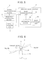
- FIG.5 is a block diagram to show the relation of the aerial photographing device 2, the total station 3, the ground base station 4, and the remotely controlling device 5.
- the ground base station 4 has the base communication unit 12, an arithmetic unit 44, and a base storage unit 45.
- the base communication unit 12 carries out communication between the aerial photographing device and the total station 3.
- the base communication unit 12 receives image data and shutter timing information of time moment when the image data have been picked up from the aerial photographing device 2, and receives coordinates data from the total station 3.
- the arithmetic unit 44 has a clock signal generating unit, associates the image data, the shutter timing information and the coordinates data, as received, with clock signals, processes the image data, the shutter timing information and the coordinates data as time series data based on the clock signals, and stores the image data, the shutter timing information and the coordinates data in the base storage unit 45.
- the base storage unit 45 has a data storage region and a program storage region. Data such as image data and coordinate data are stored in the data storage region.
- various types of programs are stored: including a calculation program required for photogrammetry, a communication program for performing communication between the base communication unit 12 and the flying vehicle communication unit 11, a program for calculating photographing positions where still images are acquired based on shutter timing and surveying data, and other programs.
- propeller motors 18a and 18b, propeller motors 18c and 18d, propeller motors 18e and 18f, and propeller motors 18g and 18h are regarded as one set respectively, and rotating and driving of each of propellers 19a and 19b, propellers 19c and 19d, propellers 19e and 19f, and propellers 19g and 19h is individually controlled.
- the flying vehicle 15 flies upward in vertical direction.
- the flying vehicle 15 is to make flight (moved) in a horizontal direction
- the flying vehicle 15 is moved in a leftward direction in the figure as shown in FIG.6
- the propeller motors 18e and 18f are rotated in increasing speed and the thrust forces of the propellers 19e and 19f are increased than the propellers 19a and 19b
- the flying vehicle 15 is tilted, and the thrust force acts in diagonally downward direction.
- a horizontal component force is generated, and the flying vehicle 15 is moved in the horizontal direction.
- the shaft 6 is maintained in vertical direction by the action of gravitational force. Therefore, optical axes of the lower camera 7 and the upper camera 8 are maintained in the vertical direction. At the same time, optical axis of the prism 9 is also maintained in the vertical direction.
- the lower camera 7 acquires images in a vertically downward direction
- the upper camera 8 acquires images in a vertically upward direction.
- the total station 3 sights the prism 9 and while tracking the prism 9, measures the position (three-dimensional coordinates) of the prism 9 in real time.
- the aerial photographing device 2 is controlled by the remotely controlling device 5, and while the aerial photographing device 2 is flying, video images are taken by the lower camera 7, and still images are acquired at the time interval as required. It is to be noted that, regarding the time interval and a timing of photographing to pick up still images may be programmed in advance, or a photographing point to pick up still images may be selected, and a command for photographing may be issued by the remotely controlling device 5. Description will be given below on a case where still images are picked up at the time interval as programmed in advance.
- the control arithmetic unit 36 issues a control command regarding the photographing of the lower camera 7 to the image pickup control unit 39. Based on the control command, the image pickup control unit 39 issues a shutter signal to the lower camera 7. Based on the shutter signal, the lower camera 7 picks up a still image. Further, the shutter signal from the image pickup control unit 39 is transmitted to the ground base station 4 via the flying vehicle communication unit 11 and image pickup time every each of the still images is recorded at the ground base station 4.
- the measurement result by the total station 3 with respect to the prism 9 is acquired at the moment when the shutter time is received, and a position (three-dimensional position) where the still image is acquired can be identified.
- positional relation between the lower camera 7 and the prism 9 is already known and fixed. Further, since the direction of the flying vehicle 15 is detected by the magnetic compass 29, it is possible to correct the measured value from the positional relationship already known and from the direction of the flying vehicle 15, and by correcting the measured value, it is possible to determine three-dimensional position of the lower camera 7, i.e. the photographing position of the lower camera 7.
- feature points are extracted by image processing such as edge processing from the first image, and the feature points common in the next still images are specified by video image tracking.
- absolute orientation is performed based on the three-dimensional coordinates of the photographing points, and photogrammetry is carried out based on the images, absolute orientation of which have been performed.
- photogrammetry may be carried out in real time every time the still image data are transmitted to the ground base station 4, or the still image data and the surveying data up to the completion of the flight may be preserved at the ground base station 4, and photogrammetry may be carried out based on the still image data and the surveying data after the flight.
- the photographing position of the still image is measured with high accuracy because the photographing position is measured by the total station 3, and further, even under the environment where radio waves from the artificial satellite do not reach, photogrammetry can be accomplished by the aerial photographing device 2.
- the position of the prism 9 is measured in real time by the total station 3 and the photographing position of the still image is acquired by synchronizing with shutter timing. Description will be given below on a case where data of distance measurement is acquired by the total station 3 at a predetermined time interval.
- FIG.7 shows a method to acquire three-dimensional coordinates of the photographing position in a case where the photographing timing and the timing to acquire the surveying data are not synchronized.
- the time of the shutter timing can be identified from a clock signal 47. Further, measurement results are acquired at I2 time intervals, and the time when each of the measurement results has been acquired can be identified from the clock signal 47.
- measurement results d1 and d2 are selected which are positioned before and after in terms of time, and the time (t1, t2) when each of the measurement results d1 and d2 has been measured are specified from the clock signal 47.
- a measured value of the shutter timing s can be obtained by interpolation with respect to the measurement results d1 and d2.
- the lower camera 7 and the upper camera 8 are provided at a lower end and at an upper end of the shaft 6 respectively, while one of these may be omitted.
- the prism 9 may be provided at the lower end of the shaft 6.
- the optical axis of the upper camera 8 is consistent with the optical axis of the prism 9, so there will be no need to correct the measurement results of the total station 3.
- the shaft 6 is supported by the gimbal 25 so as to be directed in vertical direction by the action of the gravitational force, while the shaft 6 may be arranged in such a manner that a motor is connected to each of the rocking shafts 27a and 27b (see FIG.3 ) and the rocking shafts 27a and 27b are rotated forcibly in the direction reverse to the tilting based on the tilting signal from the tilt sensor 28, so that the vertical condition is maintained.
Landscapes
- Engineering & Computer Science (AREA)
- Remote Sensing (AREA)
- Physics & Mathematics (AREA)
- General Physics & Mathematics (AREA)
- Radar, Positioning & Navigation (AREA)
- Multimedia (AREA)
- Aviation & Aerospace Engineering (AREA)
- Signal Processing (AREA)
- Microelectronics & Electronic Packaging (AREA)
- Mechanical Engineering (AREA)
- Automation & Control Theory (AREA)
- Studio Devices (AREA)
- Stereoscopic And Panoramic Photography (AREA)
- Length Measuring Devices By Optical Means (AREA)
Applications Claiming Priority (1)
| Application Number | Priority Date | Filing Date | Title |
|---|---|---|---|
| JP2013038901A JP6367522B2 (ja) | 2013-02-28 | 2013-02-28 | 航空写真システム |
Publications (3)
| Publication Number | Publication Date |
|---|---|
| EP2772725A2 true EP2772725A2 (fr) | 2014-09-03 |
| EP2772725A3 EP2772725A3 (fr) | 2016-07-06 |
| EP2772725B1 EP2772725B1 (fr) | 2019-11-06 |
Family
ID=50189505
Family Applications (1)
| Application Number | Title | Priority Date | Filing Date |
|---|---|---|---|
| EP14156375.9A Active EP2772725B1 (fr) | 2013-02-28 | 2014-02-24 | Système de photographie aérienne |
Country Status (3)
| Country | Link |
|---|---|
| US (1) | US9409656B2 (fr) |
| EP (1) | EP2772725B1 (fr) |
| JP (1) | JP6367522B2 (fr) |
Cited By (10)
| Publication number | Priority date | Publication date | Assignee | Title |
|---|---|---|---|---|
| CN105045278A (zh) * | 2015-07-09 | 2015-11-11 | 沈阳卡迩特科技有限公司 | 一种微型无人机自主感知与规避方法 |
| GB2535162A (en) * | 2015-02-09 | 2016-08-17 | Uk Air Comms Ltd | Method of performing a line-of-sight survey |
| CN107614376A (zh) * | 2015-05-19 | 2018-01-19 | 株式会社阿荣奈斯特 | 旋翼机 |
| EP3265885A4 (fr) * | 2015-03-03 | 2018-08-29 | Prenav Inc. | Balayage d'environnements et suivi de drones |
| EP3454008A1 (fr) * | 2017-09-06 | 2019-03-13 | Topcon Corporation | Dispositif, procédé et programme de traitement de données d'enquête |
| EP3632796A4 (fr) * | 2017-06-04 | 2020-06-17 | Aeronext Inc. | Véhicule aérien |
| US10893190B2 (en) | 2017-02-02 | 2021-01-12 | PreNav, Inc. | Tracking image collection for digital capture of environments, and associated systems and methods |
| US20230134289A1 (en) * | 2021-11-01 | 2023-05-04 | At&T Intellectual Property I, L.P. | Drone-based confirmation of line of sight between two geostationary fixed points |
| KR20230075540A (ko) * | 2021-11-23 | 2023-05-31 | 동아대학교 산학협력단 | 멀티스펙트럴 카메라 흔들림 방지 기능을 갖는 식생정보 취득용 드론 |
| EP4223638A1 (fr) * | 2015-11-06 | 2023-08-09 | Spherie GmbH | Aéronef sans aile |
Families Citing this family (74)
| Publication number | Priority date | Publication date | Assignee | Title |
|---|---|---|---|---|
| EP2511658A1 (fr) * | 2011-04-14 | 2012-10-17 | Hexagon Technology Center GmbH | Système de mesure et procédé de détermination de nouveau point |
| US9384668B2 (en) | 2012-05-09 | 2016-07-05 | Singularity University | Transportation using network of unmanned aerial vehicles |
| US20140263822A1 (en) * | 2013-03-18 | 2014-09-18 | Chester Charles Malveaux | Vertical take off and landing autonomous/semiautonomous/remote controlled aerial agricultural sensor platform |
| US10569868B2 (en) * | 2013-04-02 | 2020-02-25 | Hood Technology Corporation | Multicopter-assisted system and method for launching and retrieving a fixed-wing aircraft |
| US10583920B2 (en) | 2013-04-02 | 2020-03-10 | Hood Technology Corporation | Multicopter-assisted system and method for launching and retrieving a fixed-wing aircraft |
| JP5882951B2 (ja) | 2013-06-14 | 2016-03-09 | 株式会社トプコン | 飛行体誘導システム及び飛行体誘導方法 |
| JP6316568B2 (ja) | 2013-10-31 | 2018-04-25 | 株式会社トプコン | 測量システム |
| JP6326237B2 (ja) | 2014-01-31 | 2018-05-16 | 株式会社トプコン | 測定システム |
| WO2016068767A1 (fr) * | 2014-10-30 | 2016-05-06 | Acc Innovation Ab | Véhicule aérien à rotors multiples |
| JP6490401B2 (ja) | 2014-11-12 | 2019-03-27 | 株式会社トプコン | 傾斜検出システム及び傾斜検出方法 |
| CN106029501B (zh) * | 2014-12-23 | 2019-05-14 | 深圳市大疆灵眸科技有限公司 | Uav全景成像 |
| JP6567300B2 (ja) * | 2015-03-11 | 2019-08-28 | 株式会社フジタ | 無線操縦式の回転翼機 |
| JP6261090B2 (ja) * | 2015-05-18 | 2018-01-17 | 株式会社amuse oneself | 無人飛行体 |
| US10634500B2 (en) | 2015-06-29 | 2020-04-28 | Yuneec Technology Co., Limited | Aircraft and obstacle avoidance method and system thereof |
| CN106275470B (zh) * | 2015-06-29 | 2019-01-01 | 优利科技有限公司 | 飞行器及其避障方法和系统 |
| US9738399B2 (en) * | 2015-07-29 | 2017-08-22 | Hon Hai Precision Industry Co., Ltd. | Unmanned aerial vehicle control method and unmanned aerial vehicle using same |
| CN108137151B (zh) | 2015-09-11 | 2021-09-10 | 深圳市大疆灵眸科技有限公司 | 用于无人飞行器的载体 |
| EP4001111A3 (fr) * | 2015-11-10 | 2022-08-17 | Matternet, Inc. | Procédé et système de transport utilisant des véhicules aériens sans pilote |
| USD820768S1 (en) * | 2015-11-30 | 2018-06-19 | SZ DJI Technology Co., Ltd. | Aerial vehicle |
| US10882615B2 (en) * | 2015-12-09 | 2021-01-05 | Ideaforge Technology Pvt. Ltd. | Multi-rotor aerial vehicle with single arm failure redundancy |
| US10577125B1 (en) * | 2015-12-28 | 2020-03-03 | Vr Drones Llc | Multi-rotor aircraft including a split dual hemispherical attachment apparatus for virtual reality content capture and production |
| CN205707399U (zh) * | 2016-01-05 | 2016-11-23 | 深圳市大疆创新科技有限公司 | 减震结构、云台及飞行器 |
| US10416667B2 (en) | 2016-02-03 | 2019-09-17 | Sony Corporation | System and method for utilization of multiple-camera network to capture static and/or motion scenes |
| JP6691721B2 (ja) | 2016-02-15 | 2020-05-13 | 株式会社トプコン | 飛行計画作成方法及び飛行体誘導システム |
| JP6693765B2 (ja) | 2016-02-26 | 2020-05-13 | 株式会社トプコン | 飛行体追尾方法及び飛行体誘導システム |
| CN107336839A (zh) * | 2016-05-03 | 2017-11-10 | 北京星闪世图科技有限公司 | 用于拍摄全景视频的飞行器及使用该飞行器拍摄的方法 |
| JP6697340B2 (ja) * | 2016-07-04 | 2020-05-20 | オリンパス株式会社 | 撮影機器、移動撮影装置、撮影用移動体及び移動体用撮影制御装置 |
| WO2018033812A1 (fr) * | 2016-08-15 | 2018-02-22 | Uas Flightec Systems (Proprietary) Limited | Administration de substances à des animaux |
| CN109690433B (zh) | 2016-09-13 | 2022-05-17 | 杭州零零科技有限公司 | 具有环境感知的无人驾驶空中车辆系统和方法 |
| JP6796975B2 (ja) * | 2016-09-16 | 2020-12-09 | 株式会社トプコン | Uav測定装置及びuav測定システム |
| WO2018066043A1 (fr) * | 2016-10-03 | 2018-04-12 | 株式会社Aeronext | Aéronef de livraison à voilure tournante |
| JP2018084528A (ja) * | 2016-11-25 | 2018-05-31 | 株式会社トプコン | 航空写真測量装置及び航空写真測量方法 |
| US20180186472A1 (en) * | 2016-12-30 | 2018-07-05 | Airmada Technology Inc. | Method and apparatus for an unmanned aerial vehicle with a 360-degree camera system |
| US10692160B1 (en) * | 2017-01-04 | 2020-06-23 | State Farm Mutual Automobile Insurance Company | Property damage estimator |
| JP6767279B2 (ja) * | 2017-02-09 | 2020-10-14 | 株式会社トプコン | 測量システム |
| JP7355470B2 (ja) * | 2017-02-10 | 2023-10-03 | 株式会社トプコン | 測量装置、及び測量システム |
| JP6944790B2 (ja) * | 2017-02-22 | 2021-10-06 | 株式会社トプコン | 制御装置、光学装置、制御方法、無人航空機の追跡システムおよびプログラム |
| KR102623488B1 (ko) * | 2017-02-24 | 2024-01-09 | 엘에스엠트론 주식회사 | 무인 비행체의 안테나 장치 및 제어방법 |
| GB2557715B (en) * | 2017-02-28 | 2019-04-17 | Matthew Russell Iain | Unmanned aerial vehicles |
| JP6930840B2 (ja) * | 2017-03-08 | 2021-09-01 | 株式会社トプコン | 測量システム |
| JP7050425B2 (ja) | 2017-05-01 | 2022-04-08 | 株式会社トプコン | 測量システム |
| WO2019021414A1 (fr) * | 2017-07-27 | 2019-01-31 | 株式会社エアロネクスト | Aéronef à voilure tournante |
| CN113700793B (zh) * | 2017-08-28 | 2023-06-20 | 深圳市大疆创新科技有限公司 | 无人机 |
| JP7152137B2 (ja) * | 2017-08-28 | 2022-10-12 | 株式会社トプコン | 写真測量システム及び写真測量方法 |
| JP2019085104A (ja) * | 2017-11-06 | 2019-06-06 | 株式会社エアロネクスト | 飛行体及び飛行体の制御方法 |
| TWI657011B (zh) * | 2017-11-30 | 2019-04-21 | 財團法人工業技術研究院 | 無人機、無人機控制系統及控制方法 |
| CN109871027B (zh) * | 2017-12-05 | 2022-07-01 | 深圳市九天创新科技有限责任公司 | 一种倾斜摄影方法及系统 |
| JP6508320B1 (ja) * | 2017-12-28 | 2019-05-08 | D−Plan株式会社 | 無人航空機の制御システム |
| CN108341056B (zh) * | 2017-12-30 | 2024-05-07 | 浙江大学 | 一种农情监测无人机 |
| CN108318011B (zh) * | 2018-01-02 | 2020-05-15 | 中铁隧道局集团有限公司 | 一种通过无人机搭载全站仪监测施工场地周边位移的方法 |
| US11267555B2 (en) * | 2018-01-08 | 2022-03-08 | GEOSAT Aerospace & Technology | Methods and unmanned aerial vehicles for longer duration flights |
| JP7161298B2 (ja) * | 2018-03-26 | 2022-10-26 | 株式会社トプコン | ターゲット装置、測量システム |
| JP6661199B2 (ja) * | 2018-03-27 | 2020-03-11 | 株式会社エアロネクスト | 飛行体 |
| JP6473256B2 (ja) * | 2018-04-10 | 2019-02-20 | 株式会社0 | 回転翼機 |
| JP6550563B2 (ja) * | 2018-04-10 | 2019-07-31 | 株式会社エアロネクスト | 回転翼機 |
| JP6550562B2 (ja) * | 2018-04-10 | 2019-07-31 | 株式会社エアロネクスト | 回転翼機 |
| JP6550561B2 (ja) * | 2018-04-10 | 2019-07-31 | 株式会社エアロネクスト | 回転翼機 |
| JP2019189196A (ja) * | 2018-04-26 | 2019-10-31 | 宏介 津留 | アンテナやセンサーの位置関係を固定し、姿勢を安定させる、無人航空機に装着する雲台 |
| WO2019234945A1 (fr) | 2018-06-04 | 2019-12-12 | 株式会社エアロネクスト | Composant électronique et aéronef avec ledit composant électronique fixé à celui-ci |
| CN108901360B (zh) * | 2018-06-18 | 2021-11-30 | 六安科科达尔生物科技有限公司 | 双无人机协作椰子采摘机器人 |
| JP7171129B2 (ja) * | 2018-06-20 | 2022-11-15 | 西松建設株式会社 | 測量システムおよび測量方法 |
| JP6644247B1 (ja) * | 2018-07-20 | 2020-02-12 | 株式会社エアロネクスト | 飛行体 |
| CN110001945B (zh) * | 2019-04-16 | 2023-09-26 | 中国电建集团西北勘测设计研究院有限公司 | 一种倒崖立面精细倾斜航摄装置与摄影方法 |
| US11080327B2 (en) * | 2019-04-18 | 2021-08-03 | Markus Garcia | Method for the physical, in particular optical, detection of at least one usage object |
| US11235892B2 (en) | 2019-05-22 | 2022-02-01 | Hood Technology Corporation | Aircraft retrieval system and method |
| JP2021001775A (ja) * | 2019-06-20 | 2021-01-07 | 三菱電機株式会社 | 形状測定システム |
| CN110440760B (zh) * | 2019-08-14 | 2022-05-20 | 散裂中子源科学中心 | 一种高精度摄影测量目标的制备方法 |
| CN114375276B (zh) * | 2019-10-09 | 2024-12-24 | 小鹰公司 | 具有前掠翼的短距起降载具 |
| JP7009698B1 (ja) | 2020-10-07 | 2022-01-26 | エスゼット ディージェイアイ テクノロジー カンパニー リミテッド | 制御装置、撮像装置、制御方法、及びプログラム |
| CN112783202A (zh) * | 2020-12-28 | 2021-05-11 | 西北工业大学 | 一种基于万向节摄像机单元的旋翼无人机的飞行控制系统及方法 |
| CN113280791B (zh) * | 2021-06-02 | 2021-12-17 | 宿迁学院 | 一种实现地形测绘的倾斜摄影测量装置 |
| WO2023039752A1 (fr) * | 2021-09-15 | 2023-03-23 | 深圳市大疆创新科技有限公司 | Véhicule aérien sans pilote et son procédé de commande, et système ainsi que support de stockage |
| US12145753B2 (en) * | 2022-08-09 | 2024-11-19 | Pete Bitar | Compact and lightweight drone delivery device called an ArcSpear electric jet drone system having an electric ducted air propulsion system and being relatively difficult to track in flight |
| KR102705498B1 (ko) * | 2023-02-09 | 2024-09-11 | 엘아이지넥스원 주식회사 | 안테나 근접전계 측정 장치 및 방법 |
Citations (1)
| Publication number | Priority date | Publication date | Assignee | Title |
|---|---|---|---|---|
| JP2006010376A (ja) | 2004-06-23 | 2006-01-12 | Topcon Corp | ステレオ画像の関連付け方法及び3次元データ作成装置 |
Family Cites Families (35)
| Publication number | Priority date | Publication date | Assignee | Title |
|---|---|---|---|---|
| JPS55119590A (en) * | 1979-03-05 | 1980-09-13 | Mitsui Eng & Shipbuild Co Ltd | Device for maintaining underwater position of machinery |
| US4413907A (en) | 1980-11-07 | 1983-11-08 | Robert F. Deike | Remote control surveying |
| JPH01255383A (ja) * | 1988-04-05 | 1989-10-12 | Tamuko:Kk | 吊りカメラの移動制御装置 |
| JP3148900B2 (ja) | 1991-10-25 | 2001-03-26 | 清水建設株式会社 | 模型ヘリコプターを用いる3次元測量システム |
| JPH08285588A (ja) * | 1995-04-13 | 1996-11-01 | Mitsui Constr Co Ltd | 撮影装置及びこれを用いた飛行撮影装置 |
| US6369755B1 (en) | 1995-10-23 | 2002-04-09 | Trimble Navigation Limited | Integrated SATPS total survey station |
| JPH11142956A (ja) * | 1997-11-10 | 1999-05-28 | Tamagawa Seiki Co Ltd | カメラ安定台 |
| US6343254B1 (en) | 1998-10-22 | 2002-01-29 | Trimble Navigation Limited | Seamless surveying system |
| JP4332255B2 (ja) | 1999-05-14 | 2009-09-16 | 株式会社トプコン | 距離測定装置 |
| JP4276360B2 (ja) | 2000-06-26 | 2009-06-10 | 株式会社トプコン | ステレオ画像撮影用システム |
| US7071970B2 (en) * | 2003-03-10 | 2006-07-04 | Charles Benton | Video augmented orientation sensor |
| JP4301863B2 (ja) | 2003-05-21 | 2009-07-22 | 株式会社トプコン | 測距装置 |
| US7890235B2 (en) | 2005-05-27 | 2011-02-15 | The Charles Machine Works, Inc. | Determination of remote control operator position |
| US7587258B2 (en) | 2006-05-10 | 2009-09-08 | The Boeing Company | Merged laser and photogrammetry measurement using precise camera placement |
| JP5073256B2 (ja) | 2006-09-22 | 2012-11-14 | 株式会社トプコン | 位置測定装置及び位置測定方法及び位置測定プログラム |
| US9747698B2 (en) | 2006-10-21 | 2017-08-29 | Sam Stathis | System for accurately and precisely locating and marking a position in space using wireless communications and robotics |
| US9858712B2 (en) | 2007-04-09 | 2018-01-02 | Sam Stathis | System and method capable of navigating and/or mapping any multi-dimensional space |
| JP5007885B2 (ja) | 2007-10-16 | 2012-08-22 | 株式会社トプコン | 3次元測量システム及び電子的記憶媒体 |
| US11159909B2 (en) | 2008-02-05 | 2021-10-26 | Victor Thomas Anderson | Wireless location establishing device |
| US8265817B2 (en) | 2008-07-10 | 2012-09-11 | Lockheed Martin Corporation | Inertial measurement with an imaging sensor and a digitized map |
| JP5227110B2 (ja) | 2008-08-07 | 2013-07-03 | 株式会社トプコン | Gps付全方位カメラ及び空間データ収集装置 |
| US20120114229A1 (en) | 2010-01-21 | 2012-05-10 | Guoqing Zhou | Orthorectification and mosaic of video flow |
| US8774982B2 (en) * | 2010-08-26 | 2014-07-08 | Leptron Industrial Robotic Helicopters, Inc. | Helicopter with multi-rotors and wireless capability |
| JP5690541B2 (ja) | 2010-09-30 | 2015-03-25 | 株式会社トプコン | 距離測定装置 |
| WO2012049438A1 (fr) | 2010-10-12 | 2012-04-19 | Stephen James Crampton | Machine de mesure de coordonnées planante |
| JP5618840B2 (ja) * | 2011-01-04 | 2014-11-05 | 株式会社トプコン | 飛行体の飛行制御システム |
| EP2511656A1 (fr) * | 2011-04-14 | 2012-10-17 | Hexagon Technology Center GmbH | Système de mesure pour la détermination de coordonnées 3D d'une surface d'objet |
| EP2511781A1 (fr) | 2011-04-14 | 2012-10-17 | Hexagon Technology Center GmbH | Système et procédé de commande d'un aéronef sans pilote |
| EP2511658A1 (fr) | 2011-04-14 | 2012-10-17 | Hexagon Technology Center GmbH | Système de mesure et procédé de détermination de nouveau point |
| CA2780419A1 (fr) | 2011-06-17 | 2012-12-17 | National Cheng Kung University | Systeme de traitement des images pour vehicule aerien sans pilote et methode connexe |
| JP5303613B2 (ja) * | 2011-07-05 | 2013-10-02 | 株式会社五星 | 移動基準点写真測量装置および方法 |
| US8823938B2 (en) * | 2012-01-11 | 2014-09-02 | The Aerospace Corporation | System, apparatus, and method for tracking atmospheric differential absorption |
| JP5882951B2 (ja) | 2013-06-14 | 2016-03-09 | 株式会社トプコン | 飛行体誘導システム及び飛行体誘導方法 |
| JP6316568B2 (ja) | 2013-10-31 | 2018-04-25 | 株式会社トプコン | 測量システム |
| JP6326237B2 (ja) * | 2014-01-31 | 2018-05-16 | 株式会社トプコン | 測定システム |
-
2013
- 2013-02-28 JP JP2013038901A patent/JP6367522B2/ja active Active
-
2014
- 2014-02-24 EP EP14156375.9A patent/EP2772725B1/fr active Active
- 2014-02-25 US US14/188,846 patent/US9409656B2/en active Active
Patent Citations (1)
| Publication number | Priority date | Publication date | Assignee | Title |
|---|---|---|---|---|
| JP2006010376A (ja) | 2004-06-23 | 2006-01-12 | Topcon Corp | ステレオ画像の関連付け方法及び3次元データ作成装置 |
Cited By (22)
| Publication number | Priority date | Publication date | Assignee | Title |
|---|---|---|---|---|
| GB2535162A (en) * | 2015-02-09 | 2016-08-17 | Uk Air Comms Ltd | Method of performing a line-of-sight survey |
| US10671066B2 (en) | 2015-03-03 | 2020-06-02 | PreNav, Inc. | Scanning environments and tracking unmanned aerial vehicles |
| EP3265885A4 (fr) * | 2015-03-03 | 2018-08-29 | Prenav Inc. | Balayage d'environnements et suivi de drones |
| US10162353B2 (en) | 2015-03-03 | 2018-12-25 | PreNav, Inc. | Scanning environments and tracking unmanned aerial vehicles |
| US10416668B2 (en) | 2015-03-03 | 2019-09-17 | PreNav, Inc. | Scanning environments and tracking unmanned aerial vehicles |
| CN107614376A (zh) * | 2015-05-19 | 2018-01-19 | 株式会社阿荣奈斯特 | 旋翼机 |
| EP3299282A4 (fr) * | 2015-05-19 | 2018-10-17 | Aeronext Inc. | Giravion |
| US11772782B2 (en) | 2015-05-19 | 2023-10-03 | Aeronext Inc. | Rotary-wing aircraft |
| EP3954609A1 (fr) * | 2015-05-19 | 2022-02-16 | Aeronext Inc. | Aéronef à voilure tournante |
| US10814965B2 (en) | 2015-05-19 | 2020-10-27 | Aeronext Inc. | Rotary-wing aircraft |
| CN105045278A (zh) * | 2015-07-09 | 2015-11-11 | 沈阳卡迩特科技有限公司 | 一种微型无人机自主感知与规避方法 |
| EP3371050B1 (fr) * | 2015-11-06 | 2023-11-01 | Spherie GmbH | Aéronef sans ailes |
| EP4223638A1 (fr) * | 2015-11-06 | 2023-08-09 | Spherie GmbH | Aéronef sans aile |
| US10893190B2 (en) | 2017-02-02 | 2021-01-12 | PreNav, Inc. | Tracking image collection for digital capture of environments, and associated systems and methods |
| EP3632796A4 (fr) * | 2017-06-04 | 2020-06-17 | Aeronext Inc. | Véhicule aérien |
| US11148806B2 (en) | 2017-06-04 | 2021-10-19 | Aeronext Inc. | Aerial vehicle |
| US11820506B2 (en) | 2017-06-04 | 2023-11-21 | Aeronext Inc. | Aerial vehicle with counterweight mechanism |
| US10565730B2 (en) | 2017-09-06 | 2020-02-18 | Topcon Corporation | Survey data processing device, survey data processing method, and survey data processing program |
| EP3454008A1 (fr) * | 2017-09-06 | 2019-03-13 | Topcon Corporation | Dispositif, procédé et programme de traitement de données d'enquête |
| US20230134289A1 (en) * | 2021-11-01 | 2023-05-04 | At&T Intellectual Property I, L.P. | Drone-based confirmation of line of sight between two geostationary fixed points |
| US11987356B2 (en) * | 2021-11-01 | 2024-05-21 | At&T Intellectual Property I, L.P. | Drone-based confirmation of line of sight between two geostationary fixed points |
| KR20230075540A (ko) * | 2021-11-23 | 2023-05-31 | 동아대학교 산학협력단 | 멀티스펙트럴 카메라 흔들림 방지 기능을 갖는 식생정보 취득용 드론 |
Also Published As
| Publication number | Publication date |
|---|---|
| JP2014167413A (ja) | 2014-09-11 |
| JP6367522B2 (ja) | 2018-08-01 |
| EP2772725A3 (fr) | 2016-07-06 |
| US9409656B2 (en) | 2016-08-09 |
| US20140240498A1 (en) | 2014-08-28 |
| EP2772725B1 (fr) | 2019-11-06 |
Similar Documents
| Publication | Publication Date | Title |
|---|---|---|
| US9409656B2 (en) | Aerial photographing system | |
| US9609282B2 (en) | Camera for photogrammetry and aerial photographic device | |
| US10088332B2 (en) | Flight plan preparing method and flying vehicle guiding system | |
| US11009893B2 (en) | Flying vehicle tracking method, flying vehicle image acquiring method, flying vehicle displaying method and flying vehicle guiding system | |
| US8953933B2 (en) | Aerial photogrammetry and aerial photogrammetric system | |
| US9073637B2 (en) | Flying vehicle guiding system and flying vehicle guiding method | |
| JP6326237B2 (ja) | 測定システム | |
| US10800344B2 (en) | Aerial photogrammetric device and aerial photogrammetric method | |
| JP6577083B2 (ja) | 測定システム | |
| JP2020126663A (ja) | 飛行計画作成方法及び飛行体誘導システム | |
| JP6368016B2 (ja) | 航空写真システム | |
| JP6672366B2 (ja) | 測定システム | |
| JP6553134B2 (ja) | 航空写真システム |
Legal Events
| Date | Code | Title | Description |
|---|---|---|---|
| PUAI | Public reference made under article 153(3) epc to a published international application that has entered the european phase |
Free format text: ORIGINAL CODE: 0009012 |
|
| 17P | Request for examination filed |
Effective date: 20140224 |
|
| AK | Designated contracting states |
Kind code of ref document: A2 Designated state(s): AL AT BE BG CH CY CZ DE DK EE ES FI FR GB GR HR HU IE IS IT LI LT LU LV MC MK MT NL NO PL PT RO RS SE SI SK SM TR |
|
| AX | Request for extension of the european patent |
Extension state: BA ME |
|
| PUAL | Search report despatched |
Free format text: ORIGINAL CODE: 0009013 |
|
| AK | Designated contracting states |
Kind code of ref document: A3 Designated state(s): AL AT BE BG CH CY CZ DE DK EE ES FI FR GB GR HR HU IE IS IT LI LT LU LV MC MK MT NL NO PL PT RO RS SE SI SK SM TR |
|
| AX | Request for extension of the european patent |
Extension state: BA ME |
|
| RIC1 | Information provided on ipc code assigned before grant |
Ipc: G05D 1/10 20060101ALI20160531BHEP Ipc: G01C 11/02 20060101AFI20160531BHEP Ipc: G01C 15/00 20060101ALI20160531BHEP |
|
| STAA | Information on the status of an ep patent application or granted ep patent |
Free format text: STATUS: REQUEST FOR EXAMINATION WAS MADE |
|
| R17P | Request for examination filed (corrected) |
Effective date: 20161207 |
|
| RBV | Designated contracting states (corrected) |
Designated state(s): AL AT BE BG CH CY CZ DE DK EE ES FI FR GB GR HR HU IE IS IT LI LT LU LV MC MK MT NL NO PL PT RO RS SE SI SK SM TR |
|
| GRAP | Despatch of communication of intention to grant a patent |
Free format text: ORIGINAL CODE: EPIDOSNIGR1 |
|
| STAA | Information on the status of an ep patent application or granted ep patent |
Free format text: STATUS: GRANT OF PATENT IS INTENDED |
|
| INTG | Intention to grant announced |
Effective date: 20190618 |
|
| RIN1 | Information on inventor provided before grant (corrected) |
Inventor name: OTANI, HITOSHI Inventor name: OHTOMO, FUMIO Inventor name: ANAI, TETSUJI Inventor name: OSARAGI, KAZUKI |
|
| GRAS | Grant fee paid |
Free format text: ORIGINAL CODE: EPIDOSNIGR3 |
|
| GRAA | (expected) grant |
Free format text: ORIGINAL CODE: 0009210 |
|
| STAA | Information on the status of an ep patent application or granted ep patent |
Free format text: STATUS: THE PATENT HAS BEEN GRANTED |
|
| AK | Designated contracting states |
Kind code of ref document: B1 Designated state(s): AL AT BE BG CH CY CZ DE DK EE ES FI FR GB GR HR HU IE IS IT LI LT LU LV MC MK MT NL NO PL PT RO RS SE SI SK SM TR |
|
| REG | Reference to a national code |
Ref country code: GB Ref legal event code: FG4D |
|
| REG | Reference to a national code |
Ref country code: CH Ref legal event code: EP Ref country code: AT Ref legal event code: REF Ref document number: 1199346 Country of ref document: AT Kind code of ref document: T Effective date: 20191115 |
|
| REG | Reference to a national code |
Ref country code: DE Ref legal event code: R096 Ref document number: 602014056166 Country of ref document: DE |
|
| REG | Reference to a national code |
Ref country code: IE Ref legal event code: FG4D |
|
| REG | Reference to a national code |
Ref country code: NL Ref legal event code: MP Effective date: 20191106 |
|
| REG | Reference to a national code |
Ref country code: CH Ref legal event code: NV Representative=s name: VALIPAT S.A. C/O BOVARD SA NEUCHATEL, CH |
|
| REG | Reference to a national code |
Ref country code: LT Ref legal event code: MG4D |
|
| PG25 | Lapsed in a contracting state [announced via postgrant information from national office to epo] |
Ref country code: PT Free format text: LAPSE BECAUSE OF FAILURE TO SUBMIT A TRANSLATION OF THE DESCRIPTION OR TO PAY THE FEE WITHIN THE PRESCRIBED TIME-LIMIT Effective date: 20200306 Ref country code: NL Free format text: LAPSE BECAUSE OF FAILURE TO SUBMIT A TRANSLATION OF THE DESCRIPTION OR TO PAY THE FEE WITHIN THE PRESCRIBED TIME-LIMIT Effective date: 20191106 Ref country code: ES Free format text: LAPSE BECAUSE OF FAILURE TO SUBMIT A TRANSLATION OF THE DESCRIPTION OR TO PAY THE FEE WITHIN THE PRESCRIBED TIME-LIMIT Effective date: 20191106 Ref country code: LT Free format text: LAPSE BECAUSE OF FAILURE TO SUBMIT A TRANSLATION OF THE DESCRIPTION OR TO PAY THE FEE WITHIN THE PRESCRIBED TIME-LIMIT Effective date: 20191106 Ref country code: NO Free format text: LAPSE BECAUSE OF FAILURE TO SUBMIT A TRANSLATION OF THE DESCRIPTION OR TO PAY THE FEE WITHIN THE PRESCRIBED TIME-LIMIT Effective date: 20200206 Ref country code: GR Free format text: LAPSE BECAUSE OF FAILURE TO SUBMIT A TRANSLATION OF THE DESCRIPTION OR TO PAY THE FEE WITHIN THE PRESCRIBED TIME-LIMIT Effective date: 20200207 Ref country code: PL Free format text: LAPSE BECAUSE OF FAILURE TO SUBMIT A TRANSLATION OF THE DESCRIPTION OR TO PAY THE FEE WITHIN THE PRESCRIBED TIME-LIMIT Effective date: 20191106 Ref country code: LV Free format text: LAPSE BECAUSE OF FAILURE TO SUBMIT A TRANSLATION OF THE DESCRIPTION OR TO PAY THE FEE WITHIN THE PRESCRIBED TIME-LIMIT Effective date: 20191106 Ref country code: SE Free format text: LAPSE BECAUSE OF FAILURE TO SUBMIT A TRANSLATION OF THE DESCRIPTION OR TO PAY THE FEE WITHIN THE PRESCRIBED TIME-LIMIT Effective date: 20191106 Ref country code: BG Free format text: LAPSE BECAUSE OF FAILURE TO SUBMIT A TRANSLATION OF THE DESCRIPTION OR TO PAY THE FEE WITHIN THE PRESCRIBED TIME-LIMIT Effective date: 20200206 Ref country code: FI Free format text: LAPSE BECAUSE OF FAILURE TO SUBMIT A TRANSLATION OF THE DESCRIPTION OR TO PAY THE FEE WITHIN THE PRESCRIBED TIME-LIMIT Effective date: 20191106 |
|
| PG25 | Lapsed in a contracting state [announced via postgrant information from national office to epo] |
Ref country code: RS Free format text: LAPSE BECAUSE OF FAILURE TO SUBMIT A TRANSLATION OF THE DESCRIPTION OR TO PAY THE FEE WITHIN THE PRESCRIBED TIME-LIMIT Effective date: 20191106 Ref country code: IS Free format text: LAPSE BECAUSE OF FAILURE TO SUBMIT A TRANSLATION OF THE DESCRIPTION OR TO PAY THE FEE WITHIN THE PRESCRIBED TIME-LIMIT Effective date: 20200306 Ref country code: HR Free format text: LAPSE BECAUSE OF FAILURE TO SUBMIT A TRANSLATION OF THE DESCRIPTION OR TO PAY THE FEE WITHIN THE PRESCRIBED TIME-LIMIT Effective date: 20191106 |
|
| PG25 | Lapsed in a contracting state [announced via postgrant information from national office to epo] |
Ref country code: AL Free format text: LAPSE BECAUSE OF FAILURE TO SUBMIT A TRANSLATION OF THE DESCRIPTION OR TO PAY THE FEE WITHIN THE PRESCRIBED TIME-LIMIT Effective date: 20191106 |
|
| PG25 | Lapsed in a contracting state [announced via postgrant information from national office to epo] |
Ref country code: EE Free format text: LAPSE BECAUSE OF FAILURE TO SUBMIT A TRANSLATION OF THE DESCRIPTION OR TO PAY THE FEE WITHIN THE PRESCRIBED TIME-LIMIT Effective date: 20191106 Ref country code: DK Free format text: LAPSE BECAUSE OF FAILURE TO SUBMIT A TRANSLATION OF THE DESCRIPTION OR TO PAY THE FEE WITHIN THE PRESCRIBED TIME-LIMIT Effective date: 20191106 Ref country code: RO Free format text: LAPSE BECAUSE OF FAILURE TO SUBMIT A TRANSLATION OF THE DESCRIPTION OR TO PAY THE FEE WITHIN THE PRESCRIBED TIME-LIMIT Effective date: 20191106 Ref country code: CZ Free format text: LAPSE BECAUSE OF FAILURE TO SUBMIT A TRANSLATION OF THE DESCRIPTION OR TO PAY THE FEE WITHIN THE PRESCRIBED TIME-LIMIT Effective date: 20191106 |
|
| REG | Reference to a national code |
Ref country code: DE Ref legal event code: R097 Ref document number: 602014056166 Country of ref document: DE |
|
| REG | Reference to a national code |
Ref country code: AT Ref legal event code: MK05 Ref document number: 1199346 Country of ref document: AT Kind code of ref document: T Effective date: 20191106 |
|
| PG25 | Lapsed in a contracting state [announced via postgrant information from national office to epo] |
Ref country code: SM Free format text: LAPSE BECAUSE OF FAILURE TO SUBMIT A TRANSLATION OF THE DESCRIPTION OR TO PAY THE FEE WITHIN THE PRESCRIBED TIME-LIMIT Effective date: 20191106 Ref country code: SK Free format text: LAPSE BECAUSE OF FAILURE TO SUBMIT A TRANSLATION OF THE DESCRIPTION OR TO PAY THE FEE WITHIN THE PRESCRIBED TIME-LIMIT Effective date: 20191106 |
|
| PLBE | No opposition filed within time limit |
Free format text: ORIGINAL CODE: 0009261 |
|
| STAA | Information on the status of an ep patent application or granted ep patent |
Free format text: STATUS: NO OPPOSITION FILED WITHIN TIME LIMIT |
|
| 26N | No opposition filed |
Effective date: 20200807 |
|
| GBPC | Gb: european patent ceased through non-payment of renewal fee |
Effective date: 20200224 |
|
| REG | Reference to a national code |
Ref country code: BE Ref legal event code: MM Effective date: 20200229 |
|
| PG25 | Lapsed in a contracting state [announced via postgrant information from national office to epo] |
Ref country code: MC Free format text: LAPSE BECAUSE OF FAILURE TO SUBMIT A TRANSLATION OF THE DESCRIPTION OR TO PAY THE FEE WITHIN THE PRESCRIBED TIME-LIMIT Effective date: 20191106 Ref country code: LU Free format text: LAPSE BECAUSE OF NON-PAYMENT OF DUE FEES Effective date: 20200224 |
|
| PG25 | Lapsed in a contracting state [announced via postgrant information from national office to epo] |
Ref country code: SI Free format text: LAPSE BECAUSE OF FAILURE TO SUBMIT A TRANSLATION OF THE DESCRIPTION OR TO PAY THE FEE WITHIN THE PRESCRIBED TIME-LIMIT Effective date: 20191106 Ref country code: AT Free format text: LAPSE BECAUSE OF FAILURE TO SUBMIT A TRANSLATION OF THE DESCRIPTION OR TO PAY THE FEE WITHIN THE PRESCRIBED TIME-LIMIT Effective date: 20191106 |
|
| PG25 | Lapsed in a contracting state [announced via postgrant information from national office to epo] |
Ref country code: GB Free format text: LAPSE BECAUSE OF NON-PAYMENT OF DUE FEES Effective date: 20200224 Ref country code: IT Free format text: LAPSE BECAUSE OF FAILURE TO SUBMIT A TRANSLATION OF THE DESCRIPTION OR TO PAY THE FEE WITHIN THE PRESCRIBED TIME-LIMIT Effective date: 20191106 Ref country code: IE Free format text: LAPSE BECAUSE OF NON-PAYMENT OF DUE FEES Effective date: 20200224 Ref country code: FR Free format text: LAPSE BECAUSE OF NON-PAYMENT OF DUE FEES Effective date: 20200229 |
|
| PG25 | Lapsed in a contracting state [announced via postgrant information from national office to epo] |
Ref country code: BE Free format text: LAPSE BECAUSE OF NON-PAYMENT OF DUE FEES Effective date: 20200229 |
|
| PG25 | Lapsed in a contracting state [announced via postgrant information from national office to epo] |
Ref country code: TR Free format text: LAPSE BECAUSE OF FAILURE TO SUBMIT A TRANSLATION OF THE DESCRIPTION OR TO PAY THE FEE WITHIN THE PRESCRIBED TIME-LIMIT Effective date: 20191106 Ref country code: MT Free format text: LAPSE BECAUSE OF FAILURE TO SUBMIT A TRANSLATION OF THE DESCRIPTION OR TO PAY THE FEE WITHIN THE PRESCRIBED TIME-LIMIT Effective date: 20191106 Ref country code: CY Free format text: LAPSE BECAUSE OF FAILURE TO SUBMIT A TRANSLATION OF THE DESCRIPTION OR TO PAY THE FEE WITHIN THE PRESCRIBED TIME-LIMIT Effective date: 20191106 |
|
| PG25 | Lapsed in a contracting state [announced via postgrant information from national office to epo] |
Ref country code: MK Free format text: LAPSE BECAUSE OF FAILURE TO SUBMIT A TRANSLATION OF THE DESCRIPTION OR TO PAY THE FEE WITHIN THE PRESCRIBED TIME-LIMIT Effective date: 20191106 |
|
| REG | Reference to a national code |
Ref country code: CH Ref legal event code: U11 Free format text: ST27 STATUS EVENT CODE: U-0-0-U10-U11 (AS PROVIDED BY THE NATIONAL OFFICE) Effective date: 20260301 |
|
| PGFP | Annual fee paid to national office [announced via postgrant information from national office to epo] |
Ref country code: DE Payment date: 20260102 Year of fee payment: 13 |
|
| PGFP | Annual fee paid to national office [announced via postgrant information from national office to epo] |
Ref country code: CH Payment date: 20260301 Year of fee payment: 13 |