EP2773586B1 - Élément micromécanique, composant muni d'un élément micromécanique et procédé de fabrication d'un composant - Google Patents
Élément micromécanique, composant muni d'un élément micromécanique et procédé de fabrication d'un composant Download PDFInfo
- Publication number
- EP2773586B1 EP2773586B1 EP12790454.8A EP12790454A EP2773586B1 EP 2773586 B1 EP2773586 B1 EP 2773586B1 EP 12790454 A EP12790454 A EP 12790454A EP 2773586 B1 EP2773586 B1 EP 2773586B1
- Authority
- EP
- European Patent Office
- Prior art keywords
- component
- micromechanical
- sensor element
- control electronics
- micromechanical element
- Prior art date
- Legal status (The legal status is an assumption and is not a legal conclusion. Google has not performed a legal analysis and makes no representation as to the accuracy of the status listed.)
- Active
Links
Images

Classifications
-
- G—PHYSICS
- G01—MEASURING; TESTING
- G01P—MEASURING LINEAR OR ANGULAR SPEED, ACCELERATION, DECELERATION, OR SHOCK; INDICATING PRESENCE, ABSENCE, OR DIRECTION, OF MOVEMENT
- G01P15/00—Measuring acceleration; Measuring deceleration; Measuring shock, i.e. sudden change of acceleration
- G01P15/02—Measuring acceleration; Measuring deceleration; Measuring shock, i.e. sudden change of acceleration by making use of inertia forces using solid seismic masses
- G01P15/08—Measuring acceleration; Measuring deceleration; Measuring shock, i.e. sudden change of acceleration by making use of inertia forces using solid seismic masses with conversion into electric or magnetic values
- G01P15/0888—Measuring acceleration; Measuring deceleration; Measuring shock, i.e. sudden change of acceleration by making use of inertia forces using solid seismic masses with conversion into electric or magnetic values for indicating angular acceleration
-
- B—PERFORMING OPERATIONS; TRANSPORTING
- B81—MICROSTRUCTURAL TECHNOLOGY
- B81B—MICROSTRUCTURAL DEVICES OR SYSTEMS, e.g. MICROMECHANICAL DEVICES
- B81B7/00—Microstructural systems ; Auxiliary parts of microstructural devices or systems
- B81B7/02—Microstructural systems ; Auxiliary parts of microstructural devices or systems containing distinct electrical or optical devices of particular relevance for their function, e.g. microelectro-mechanical systems [MEMS]
-
- B—PERFORMING OPERATIONS; TRANSPORTING
- B81—MICROSTRUCTURAL TECHNOLOGY
- B81C—PROCESSES OR APPARATUS SPECIALLY ADAPTED FOR THE MANUFACTURE OR TREATMENT OF MICROSTRUCTURAL DEVICES OR SYSTEMS
- B81C1/00—Manufacture or treatment of devices or systems in or on a substrate
- B81C1/00015—Manufacture or treatment of devices or systems in or on a substrate for manufacturing microsystems
- B81C1/00222—Integrating an electronic processing unit with a micromechanical structure
- B81C1/0023—Packaging together an electronic processing unit die and a micromechanical structure die
-
- B—PERFORMING OPERATIONS; TRANSPORTING
- B81—MICROSTRUCTURAL TECHNOLOGY
- B81B—MICROSTRUCTURAL DEVICES OR SYSTEMS, e.g. MICROMECHANICAL DEVICES
- B81B2201/00—Specific applications of microelectromechanical systems
- B81B2201/02—Sensors
- B81B2201/0228—Inertial sensors
- B81B2201/0235—Accelerometers
-
- B—PERFORMING OPERATIONS; TRANSPORTING
- B81—MICROSTRUCTURAL TECHNOLOGY
- B81B—MICROSTRUCTURAL DEVICES OR SYSTEMS, e.g. MICROMECHANICAL DEVICES
- B81B2201/00—Specific applications of microelectromechanical systems
- B81B2201/02—Sensors
- B81B2201/0228—Inertial sensors
- B81B2201/0242—Gyroscopes
-
- B—PERFORMING OPERATIONS; TRANSPORTING
- B81—MICROSTRUCTURAL TECHNOLOGY
- B81B—MICROSTRUCTURAL DEVICES OR SYSTEMS, e.g. MICROMECHANICAL DEVICES
- B81B2201/00—Specific applications of microelectromechanical systems
- B81B2201/02—Sensors
- B81B2201/0264—Pressure sensors
-
- B—PERFORMING OPERATIONS; TRANSPORTING
- B81—MICROSTRUCTURAL TECHNOLOGY
- B81B—MICROSTRUCTURAL DEVICES OR SYSTEMS, e.g. MICROMECHANICAL DEVICES
- B81B2201/00—Specific applications of microelectromechanical systems
- B81B2201/02—Sensors
- B81B2201/0278—Temperature sensors
-
- Y—GENERAL TAGGING OF NEW TECHNOLOGICAL DEVELOPMENTS; GENERAL TAGGING OF CROSS-SECTIONAL TECHNOLOGIES SPANNING OVER SEVERAL SECTIONS OF THE IPC; TECHNICAL SUBJECTS COVERED BY FORMER USPC CROSS-REFERENCE ART COLLECTIONS [XRACs] AND DIGESTS
- Y10—TECHNICAL SUBJECTS COVERED BY FORMER USPC
- Y10T—TECHNICAL SUBJECTS COVERED BY FORMER US CLASSIFICATION
- Y10T29/00—Metal working
- Y10T29/49—Method of mechanical manufacture
- Y10T29/49002—Electrical device making
Definitions
- the invention relates to a micromechanical element, a component with a micromechanical element and a method for producing a component.
- an airbag function uses acceleration information along a longitudinal axis and along a transverse axis of the vehicle with a measuring range of up to 500-1000 m / s 2 .
- acceleration sensor information in the range of up to 20 m / s 2 is required in addition to measuring the rotational speed around the vertical axis of the vehicle.
- separate sensors are conventionally used to measure the acceleration for different measuring ranges.
- the invention is based on the object of proposing solutions in order to be able to provide different physical measured variables with a single device.
- the invention is based on the idea of providing a micromechanical element, a component with a micromechanical element and a method for producing the component.
- the micromechanical element which can be part of a component, has a plurality of individual sensor elements, the individual sensor elements of a micromechanical element being arranged in a housing of a component and being arranged in areas that are hermetically separated from one another.
- a first individual sensor element is a rotation rate sensor element (1'a), a second individual sensor element an acceleration sensor element (2'a) with a low measuring range and a third individual sensor element, an acceleration sensor element (3'a) with a high measuring range.
- sensors for measuring rotational speeds and accelerations with an extended measuring range can be provided.
- different physical measured variables such as acceleration, speed, rate of rotation, pressure, temperature and angle, such as the angle of inclination, can be measured over time.
- a combination of individual sensor elements that can record physical measured quantities from different areas extends the measuring range of the individual sensor elements. This is particularly advantageous when measuring an acceleration in vehicles.
- low acceleration values as well as high acceleration values can be measured with a similar precision with the aid of a single micromechanical element within a component.
- Control units or control electronics units, which are also arranged in the component, can further process the recorded measured values.
- the measurement of rotational speeds and accelerations with an extended measuring range can thus be made available with a single component or sensor.
- An integration of elements on a single electromechanical element or chip can be provided, for example, by integrating different micromechanical structures under different gas pressures on a chip in order to perform different measurement tasks. Here it is possible to provide different requirements with the aid of differently adjustable pressures in the chip.
- the sensors according to the invention for the measurement of the longitudinal and transverse acceleration of a vehicle in the low and in the high measurement range, as well as the detection of the rotational speed around the vertical axis of a vehicle.
- the manufacturing processes for the acceleration sensors and the yaw rate sensors are designed to be similar, so that the same technology platform can be used by harmonizing the processes or method steps in the manufacture of the two sensor types.
- the integration represents a reduction in the costs for the construction and connection technology, since fewer elements have to be processed.
- a combined micromechanical element can also be produced more cost-effectively, since structures such as frames can be saved.
- there is the space requirement of a single element is lower compared to an arrangement with several elements.
- Crash situations can also be recognized early if strong and abrupt braking, which takes place in the lower acceleration range, is recognized and implemented in an airbag deployment method. Due to signal transit time and phase differences between separately working, physically independent acceleration sensors, there may be disadvantages in the design of the triggering method. These disadvantages can now be overcome with the aid of the proposed arrangements.
- Developments of the method can be method steps that implement the features of the specified components in accordance with the subclaims.
- Fig. 1 shows a conventional arrangement of components 101, 102, 103.
- a micromechanical rotation rate sensor element 1a is usually arranged here together with an electronic control unit 1b in a common housing 1c.
- An acceleration sensor element with a low measuring range 2a and an acceleration sensor element with a high measuring range 3a and corresponding control electronics for the low measuring range 2b and for the high measuring range 3b are also packaged and each arranged in a common housing 2c and 3c.
- three individual components 101, 102, 102 are used, in each of which micromechanical elements 1a, 1b or 2a, 2b or 3a, 3b are located.
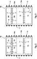
- Fig. 2 shows a first exemplary embodiment of an arrangement according to the invention of a component 100.
- a single micromechanical element 123a here a sensor element in a chip, has a plurality of individual elements 1'a, 2'a, 3'a.
- the individual elements 1'a, 2'a, 3'a can occupy areas within the common chip 123a which are hermetically separated from one another and which can enclose different pressures.
- the respective control electronics are arranged on separate units 1'b, 2'b, 3'b and are accommodated with the sensor element 123a in a common housing 123c.
- an acceleration measurement can be covered in a large measuring range with both low and high acceleration values, for example from about 1 m / s 2 to about 1000 m / s 2 .
- a single element can also cover such a measurement range by providing an acceleration sensor unit 23a, as in FIG Fig. 3 and 4th shown.
- Fig. 3 shows a micromechanical element 123a, which is not part of the invention, with a rotation rate sensor 1'a and with a combined acceleration sensor unit 23a.
- the individual elements 1'a and 23a can occupy areas within the common chip 123a which are hermetically separated from one another and which enclose different pressures.
- the respective control electronics are located on separate units 1'b, 23b and are accommodated with the sensor element 123a in a common housing 123c.
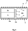
- FIG. 4 Figure 3 shows another element not forming part of the invention.
- the component 100 has a combination of a rotation rate sensor 1'a with a combined acceleration sensor unit 23a, for example a combination 23a for measuring high acceleration values and low acceleration values in one unit.
- the individual elements 1'a and 23a can occupy areas within the common chip 123a which are hermetically separated from one another and which enclose different pressures in order to provide different response characteristics in this way.
- the control electronics for all the individual elements 23a, 1'a are located on a single unit 123b and are accommodated with the sensor element 123a in a common housing 123c of the component 100.
- Fig. 3 and 4th is within the housing 123c of the Component 100 each at least one micromechanical element 123a and at least one control device 1'b, 2'b, 3'b, 23b, 123b arranged.
- the micromechanical element 123a has at least two individual sensor elements 1'a, 2'a, 3'a, 23a.
- An electronic control unit 1'b, 2'b, 3'b, 23b, 123b can be assigned to each individual sensor element 1'a, 2'a, 3'a, 23a.
- the micromechanical element 123a is available for at least two measurement tasks, so that at least one control device 1'b, 2'b, 3'b, 23b, 123b is connected to the micromechanical element 123a.
- the micromechanical element 123a and the control devices 1'b, 2'b, 3'b, 23b, 123b are each electrically connected to one another via a first connection geometry 11.
- the control devices 1'b, 2'b, 3'b, 23b, 123b each have a second connection geometry 12, which is electrically connected to a third connection geometry 13 of the component 100. With the third connection geometry 13, the component 100 can be contacted with an external electrical circuit.
Landscapes
- Engineering & Computer Science (AREA)
- Microelectronics & Electronic Packaging (AREA)
- Manufacturing & Machinery (AREA)
- Computer Hardware Design (AREA)
- Physics & Mathematics (AREA)
- General Physics & Mathematics (AREA)
- Pressure Sensors (AREA)
- Micromachines (AREA)
- Measuring Fluid Pressure (AREA)
Claims (7)
- Elément micromécanique (123a) présentant une pluralité d'éléments capteurs individuels (1'a, 2'a, 3'a, 23a), un premier élément capteur individuel (1'a) étant un élément capteur de vitesse de rotation (1'a), un deuxième élément capteur individuel étant un élément capteur d'accélération (2'a) à plage de mesure basse, et un troisième élément capteur individuel étant un élément capteur d'accélération (3'a) à plage de mesure haute, les éléments capteurs individuels (1'a, 2'a, 3'a, 23a) étant disposés respectivement dans des zones de l'élément micromécanique (123a) séparées hermétiquement les unes des autres.
- Elément micromécanique (123a) selon la revendication 1, dans lequel les zones présentent différentes pressions.
- Composant (100) permettant de mesurer au moins deux grandeurs de mesure physiques, présentant- un élément micromécanique (123a) selon la revendication 1 ;- au moins une unité électronique de régulation (1'b, 2'b, 3'b) qui peut être reliée électriquement à l'élément micromécanique (123a) ;- l'élément micromécanique (123a) et l'unité électronique de régulation (1'b, 2'b, 3'b) étant disposés dans un boîtier commun (123c).
- Composant (100) selon la revendication 3, dans lequel au moins un élément capteur individuel (1'a, 2'a, 3'a) est relié électriquement par une première géométrie de connexion (11) à l'unité électronique de régulation (1'b, 2'b, 3'b) à l'intérieur du boîtier (123c) .
- Composant (100) selon la revendication 4, dans lequel l'unité électronique de régulation (1'b, 2'b, 3'b) présente une deuxième géométrie de connexion (12) qui est reliée électriquement à une troisième géométrie de connexion (13) du composant (100).
- Composant (100) selon l'une quelconque des revendications 3 à 5, dans lequel l'élément micromécanique (123a) est disposé au centre géométrique entre une première unité électronique de régulation (1'b, 2'b, 3'b) et une deuxième unité électronique de régulation (1'b, 2'b, 3'b).
- Procédé de fabrication d'un composant (100), présentant les étapes consistant à :- prévoir un composant (100) qui présente un élément micromécanique (123a) doté d'une pluralité d'éléments capteurs individuels (1'a, 2'a, 3'a, 23a), un premier élément capteur individuel (1'a) étant un élément capteur de vitesse de rotation 1'a, un deuxième élément capteur individuel étant un élément capteur d'accélération 2'a à plage de mesure basse 2a, et un troisième élément capteur individuel étant un élément capteur d'accélération (3'a) à plage de mesure haute, les éléments capteurs individuels (1'a, 2'a, 3'a, 23a) étant disposés dans des zones de l'élément micromécanique (123a) séparées hermétiquement les unes des autres ;- prévoir au moins une unité électronique de régulation (1'b, 2'b, 3'b) ;- relier électriquement l'élément micromécanique (123a) à l'unité électronique de régulation (1'b, 2'b, 3'b) ; et- disposer l'élément micromécanique (123a) et l'unité électronique de régulation (1'b, 2'b, 3'b) dans un boîtier commun (123c).
Applications Claiming Priority (2)
| Application Number | Priority Date | Filing Date | Title |
|---|---|---|---|
| DE102011085727A DE102011085727A1 (de) | 2011-11-03 | 2011-11-03 | Mikromechanisches Element, Bauelement mit einem mikromechanischen Element und Verfahren zum Herstellen eines Bauelements |
| PCT/EP2012/071724 WO2013064634A2 (fr) | 2011-11-03 | 2012-11-02 | Élément micromécanique, composant muni d'un élément micromécanique et procédé de fabrication d'un composant |
Publications (2)
| Publication Number | Publication Date |
|---|---|
| EP2773586A2 EP2773586A2 (fr) | 2014-09-10 |
| EP2773586B1 true EP2773586B1 (fr) | 2021-03-24 |
Family
ID=47221321
Family Applications (1)
| Application Number | Title | Priority Date | Filing Date |
|---|---|---|---|
| EP12790454.8A Active EP2773586B1 (fr) | 2011-11-03 | 2012-11-02 | Élément micromécanique, composant muni d'un élément micromécanique et procédé de fabrication d'un composant |
Country Status (5)
| Country | Link |
|---|---|
| US (1) | US20140283603A1 (fr) |
| EP (1) | EP2773586B1 (fr) |
| CN (1) | CN104024144B (fr) |
| DE (1) | DE102011085727A1 (fr) |
| WO (1) | WO2013064634A2 (fr) |
Families Citing this family (2)
| Publication number | Priority date | Publication date | Assignee | Title |
|---|---|---|---|---|
| JP7375522B2 (ja) * | 2019-12-20 | 2023-11-08 | セイコーエプソン株式会社 | センサーユニット、電子機器および移動体 |
| DE102020211741A1 (de) * | 2020-09-21 | 2022-03-24 | Robert Bosch Gesellschaft mit beschränkter Haftung | Mikromechanischer Sensor |
Family Cites Families (13)
| Publication number | Priority date | Publication date | Assignee | Title |
|---|---|---|---|---|
| DE4228893B4 (de) * | 1992-08-29 | 2004-04-08 | Robert Bosch Gmbh | System zur Beeinflussung der Fahrdynamik eines Kraftfahrzeugs |
| JP3435665B2 (ja) * | 2000-06-23 | 2003-08-11 | 株式会社村田製作所 | 複合センサ素子およびその製造方法 |
| WO2005088317A1 (fr) * | 2004-03-16 | 2005-09-22 | Continental Teves Ag & Co.Ohg | Dispositif detecteur |
| EP1775259A1 (fr) * | 2005-10-14 | 2007-04-18 | STMicroelectronics S.r.l. | Boîtier sur tranche pour capteurs |
| WO2008026331A1 (fr) | 2006-09-01 | 2008-03-06 | Alps Electric Co., Ltd. | Capteur capacitif d'accélération |
| DE102007060632A1 (de) * | 2007-12-17 | 2009-06-18 | Robert Bosch Gmbh | Verfahren zum Herstellen eines Kappenwafers für einen Sensor |
| JP5319122B2 (ja) | 2008-01-21 | 2013-10-16 | 日立オートモティブシステムズ株式会社 | 慣性センサ |
| DE102009012268B4 (de) * | 2008-03-11 | 2020-12-24 | Continental Teves Ag & Co. Ohg | Sensoreinrichtung zum Erfassen wenigstens einer Drehrate einer Drehbewegung |
| DE102008040970A1 (de) * | 2008-08-04 | 2010-02-11 | Robert Bosch Gmbh | Mikromechanische Vorrichtung mit Kavernen mit unterschiedlichem atmosphärischen Innendruck |
| JP2010054212A (ja) * | 2008-08-26 | 2010-03-11 | Panasonic Electric Works Co Ltd | 静電容量型半導体物理量センサ |
| DE102009027330A1 (de) * | 2009-06-30 | 2011-01-05 | Robert Bosch Gmbh | Sensoranordnung und Verwendung einer Sensoranordnung |
| DE102009029180B4 (de) * | 2009-09-03 | 2017-07-20 | Robert Bosch Gmbh | Mikrosystem |
| US20110227173A1 (en) * | 2010-03-17 | 2011-09-22 | Honeywell International Inc. | Mems sensor with integrated asic packaging |
-
2011
- 2011-11-03 DE DE102011085727A patent/DE102011085727A1/de not_active Withdrawn
-
2012
- 2012-11-02 US US14/355,428 patent/US20140283603A1/en not_active Abandoned
- 2012-11-02 EP EP12790454.8A patent/EP2773586B1/fr active Active
- 2012-11-02 CN CN201280065850.9A patent/CN104024144B/zh active Active
- 2012-11-02 WO PCT/EP2012/071724 patent/WO2013064634A2/fr not_active Ceased
Non-Patent Citations (1)
| Title |
|---|
| None * |
Also Published As
| Publication number | Publication date |
|---|---|
| WO2013064634A2 (fr) | 2013-05-10 |
| WO2013064634A3 (fr) | 2013-08-15 |
| EP2773586A2 (fr) | 2014-09-10 |
| CN104024144B (zh) | 2016-09-28 |
| US20140283603A1 (en) | 2014-09-25 |
| CN104024144A (zh) | 2014-09-03 |
| DE102011085727A1 (de) | 2013-05-08 |
Similar Documents
| Publication | Publication Date | Title |
|---|---|---|
| EP1979709B1 (fr) | Systeme a sondes d'inertie | |
| DE102009012268B4 (de) | Sensoreinrichtung zum Erfassen wenigstens einer Drehrate einer Drehbewegung | |
| EP2106551B1 (fr) | Capteur d'accélération micromécanique à plusieurs axes | |
| DE102016109328A1 (de) | Z-Achsen-Beschleunigungsmesser-Auslegung mit Offset-Kompensation | |
| EP1671086A1 (fr) | Capteur de vehicule pour determiner une acceleration et un bruit de structure | |
| WO2014095316A2 (fr) | Dispositif électronique et procédé de production d'un dispositif électronique | |
| DE102020204773A1 (de) | Sensoranordnung, umfassend eine Mehrzahl von einzelnen und separaten Sensorelementen | |
| EP2773586B1 (fr) | Élément micromécanique, composant muni d'un élément micromécanique et procédé de fabrication d'un composant | |
| EP3194897B1 (fr) | Détection d'humidité au sein d'un capteur | |
| EP3167253B1 (fr) | Découplage de vibration de capteurs | |
| EP1728055A1 (fr) | Detecteur de vehicule destine a la detection de bruits de structure | |
| DE102013211378A1 (de) | Mikromechanische Feuchtesensorvorrichtung und entsprechendes Herstellungsverfahren sowie mikromechanische Sensoranordnung | |
| WO2015162014A1 (fr) | Surveillance d'un capteur inertiel 3 axes au moyen d'un capteur inertiel 2 axes | |
| DE19715575C1 (de) | Verfahren zur richtungsselektiven Ausrichtung einer passiven Sicherheitseinrichtung | |
| EP1118508B1 (fr) | Méthode de contrôle d'un reseau de capteurs de direction et des capteurs d'accélération correspondant | |
| DE102004015474A1 (de) | Aufnehmersystem/Auslösesensor, geeignet für Diagnose-/Sicherheitsvorrichtung, insbesondere für Unfallschutzeinrichtungen in einem Fahrzeug | |
| DE102009045393A1 (de) | Mikromechanisches Bauelement | |
| DE19939984C2 (de) | Verfahren zur richtungsselektiven Ausrichtung einer passiven Sicherheitseinrichtung | |
| DE102019200839A1 (de) | Mikromechanischer Inertialsensor | |
| DE102004022831A1 (de) | Aufnehmersystem/Auslösesensor, geeignet für Diagnose-/Sicherheitsvorrichtung, insbesondere für Unfallschutzeinrichtungen in einem Fahrzeug | |
| WO2005088317A1 (fr) | Dispositif detecteur | |
| EP3722769B1 (fr) | Module électronique et son procédé de fabrication | |
| DE102015207856A1 (de) | Drehratensensor und Verfahren | |
| DE112015000515T5 (de) | Beschleunigungssensor | |
| DE102004022808A1 (de) | Aufnehmersystem/Auslösesensor, geeignet für Diagnose-/Sicherheitsvorrichtung, insbesondere für Unfallschutzeinrichtungen in einem Fahrzeug |
Legal Events
| Date | Code | Title | Description |
|---|---|---|---|
| PUAI | Public reference made under article 153(3) epc to a published international application that has entered the european phase |
Free format text: ORIGINAL CODE: 0009012 |
|
| 17P | Request for examination filed |
Effective date: 20140603 |
|
| AK | Designated contracting states |
Kind code of ref document: A2 Designated state(s): AL AT BE BG CH CY CZ DE DK EE ES FI FR GB GR HR HU IE IS IT LI LT LU LV MC MK MT NL NO PL PT RO RS SE SI SK SM TR |
|
| RIN1 | Information on inventor provided before grant (corrected) |
Inventor name: SCHMID, BERNHARD Inventor name: GUENTHNER, STEFAN |
|
| DAX | Request for extension of the european patent (deleted) | ||
| STAA | Information on the status of an ep patent application or granted ep patent |
Free format text: STATUS: EXAMINATION IS IN PROGRESS |
|
| 17Q | First examination report despatched |
Effective date: 20180118 |
|
| RAP1 | Party data changed (applicant data changed or rights of an application transferred) |
Owner name: CONTINENTAL TEVES AG & CO. OHG |
|
| GRAP | Despatch of communication of intention to grant a patent |
Free format text: ORIGINAL CODE: EPIDOSNIGR1 |
|
| STAA | Information on the status of an ep patent application or granted ep patent |
Free format text: STATUS: GRANT OF PATENT IS INTENDED |
|
| INTG | Intention to grant announced |
Effective date: 20201123 |
|
| GRAS | Grant fee paid |
Free format text: ORIGINAL CODE: EPIDOSNIGR3 |
|
| GRAA | (expected) grant |
Free format text: ORIGINAL CODE: 0009210 |
|
| STAA | Information on the status of an ep patent application or granted ep patent |
Free format text: STATUS: THE PATENT HAS BEEN GRANTED |
|
| AK | Designated contracting states |
Kind code of ref document: B1 Designated state(s): AL AT BE BG CH CY CZ DE DK EE ES FI FR GB GR HR HU IE IS IT LI LT LU LV MC MK MT NL NO PL PT RO RS SE SI SK SM TR |
|
| REG | Reference to a national code |
Ref country code: GB Ref legal event code: FG4D Free format text: NOT ENGLISH |
|
| REG | Reference to a national code |
Ref country code: CH Ref legal event code: EP |
|
| REG | Reference to a national code |
Ref country code: IE Ref legal event code: FG4D Free format text: LANGUAGE OF EP DOCUMENT: GERMAN |
|
| REG | Reference to a national code |
Ref country code: AT Ref legal event code: REF Ref document number: 1374316 Country of ref document: AT Kind code of ref document: T Effective date: 20210415 Ref country code: DE Ref legal event code: R096 Ref document number: 502012016691 Country of ref document: DE |
|
| REG | Reference to a national code |
Ref country code: FI Ref legal event code: FGE |
|
| REG | Reference to a national code |
Ref country code: LT Ref legal event code: MG9D |
|
| PG25 | Lapsed in a contracting state [announced via postgrant information from national office to epo] |
Ref country code: HR Free format text: LAPSE BECAUSE OF FAILURE TO SUBMIT A TRANSLATION OF THE DESCRIPTION OR TO PAY THE FEE WITHIN THE PRESCRIBED TIME-LIMIT Effective date: 20210324 Ref country code: GR Free format text: LAPSE BECAUSE OF FAILURE TO SUBMIT A TRANSLATION OF THE DESCRIPTION OR TO PAY THE FEE WITHIN THE PRESCRIBED TIME-LIMIT Effective date: 20210625 Ref country code: BG Free format text: LAPSE BECAUSE OF FAILURE TO SUBMIT A TRANSLATION OF THE DESCRIPTION OR TO PAY THE FEE WITHIN THE PRESCRIBED TIME-LIMIT Effective date: 20210624 Ref country code: NO Free format text: LAPSE BECAUSE OF FAILURE TO SUBMIT A TRANSLATION OF THE DESCRIPTION OR TO PAY THE FEE WITHIN THE PRESCRIBED TIME-LIMIT Effective date: 20210624 |
|
| PG25 | Lapsed in a contracting state [announced via postgrant information from national office to epo] |
Ref country code: RS Free format text: LAPSE BECAUSE OF FAILURE TO SUBMIT A TRANSLATION OF THE DESCRIPTION OR TO PAY THE FEE WITHIN THE PRESCRIBED TIME-LIMIT Effective date: 20210324 Ref country code: LV Free format text: LAPSE BECAUSE OF FAILURE TO SUBMIT A TRANSLATION OF THE DESCRIPTION OR TO PAY THE FEE WITHIN THE PRESCRIBED TIME-LIMIT Effective date: 20210324 Ref country code: SE Free format text: LAPSE BECAUSE OF FAILURE TO SUBMIT A TRANSLATION OF THE DESCRIPTION OR TO PAY THE FEE WITHIN THE PRESCRIBED TIME-LIMIT Effective date: 20210324 |
|
| REG | Reference to a national code |
Ref country code: NL Ref legal event code: MP Effective date: 20210324 |
|
| PG25 | Lapsed in a contracting state [announced via postgrant information from national office to epo] |
Ref country code: NL Free format text: LAPSE BECAUSE OF FAILURE TO SUBMIT A TRANSLATION OF THE DESCRIPTION OR TO PAY THE FEE WITHIN THE PRESCRIBED TIME-LIMIT Effective date: 20210324 |
|
| PG25 | Lapsed in a contracting state [announced via postgrant information from national office to epo] |
Ref country code: SM Free format text: LAPSE BECAUSE OF FAILURE TO SUBMIT A TRANSLATION OF THE DESCRIPTION OR TO PAY THE FEE WITHIN THE PRESCRIBED TIME-LIMIT Effective date: 20210324 Ref country code: LT Free format text: LAPSE BECAUSE OF FAILURE TO SUBMIT A TRANSLATION OF THE DESCRIPTION OR TO PAY THE FEE WITHIN THE PRESCRIBED TIME-LIMIT Effective date: 20210324 Ref country code: CZ Free format text: LAPSE BECAUSE OF FAILURE TO SUBMIT A TRANSLATION OF THE DESCRIPTION OR TO PAY THE FEE WITHIN THE PRESCRIBED TIME-LIMIT Effective date: 20210324 Ref country code: EE Free format text: LAPSE BECAUSE OF FAILURE TO SUBMIT A TRANSLATION OF THE DESCRIPTION OR TO PAY THE FEE WITHIN THE PRESCRIBED TIME-LIMIT Effective date: 20210324 |
|
| PG25 | Lapsed in a contracting state [announced via postgrant information from national office to epo] |
Ref country code: IS Free format text: LAPSE BECAUSE OF FAILURE TO SUBMIT A TRANSLATION OF THE DESCRIPTION OR TO PAY THE FEE WITHIN THE PRESCRIBED TIME-LIMIT Effective date: 20210724 Ref country code: RO Free format text: LAPSE BECAUSE OF FAILURE TO SUBMIT A TRANSLATION OF THE DESCRIPTION OR TO PAY THE FEE WITHIN THE PRESCRIBED TIME-LIMIT Effective date: 20210324 Ref country code: SK Free format text: LAPSE BECAUSE OF FAILURE TO SUBMIT A TRANSLATION OF THE DESCRIPTION OR TO PAY THE FEE WITHIN THE PRESCRIBED TIME-LIMIT Effective date: 20210324 Ref country code: PL Free format text: LAPSE BECAUSE OF FAILURE TO SUBMIT A TRANSLATION OF THE DESCRIPTION OR TO PAY THE FEE WITHIN THE PRESCRIBED TIME-LIMIT Effective date: 20210324 Ref country code: PT Free format text: LAPSE BECAUSE OF FAILURE TO SUBMIT A TRANSLATION OF THE DESCRIPTION OR TO PAY THE FEE WITHIN THE PRESCRIBED TIME-LIMIT Effective date: 20210726 Ref country code: ES Free format text: LAPSE BECAUSE OF FAILURE TO SUBMIT A TRANSLATION OF THE DESCRIPTION OR TO PAY THE FEE WITHIN THE PRESCRIBED TIME-LIMIT Effective date: 20210324 |
|
| REG | Reference to a national code |
Ref country code: DE Ref legal event code: R097 Ref document number: 502012016691 Country of ref document: DE |
|
| PG25 | Lapsed in a contracting state [announced via postgrant information from national office to epo] |
Ref country code: DK Free format text: LAPSE BECAUSE OF FAILURE TO SUBMIT A TRANSLATION OF THE DESCRIPTION OR TO PAY THE FEE WITHIN THE PRESCRIBED TIME-LIMIT Effective date: 20210324 Ref country code: AL Free format text: LAPSE BECAUSE OF FAILURE TO SUBMIT A TRANSLATION OF THE DESCRIPTION OR TO PAY THE FEE WITHIN THE PRESCRIBED TIME-LIMIT Effective date: 20210324 |
|
| PLBE | No opposition filed within time limit |
Free format text: ORIGINAL CODE: 0009261 |
|
| STAA | Information on the status of an ep patent application or granted ep patent |
Free format text: STATUS: NO OPPOSITION FILED WITHIN TIME LIMIT |
|
| PG25 | Lapsed in a contracting state [announced via postgrant information from national office to epo] |
Ref country code: SI Free format text: LAPSE BECAUSE OF FAILURE TO SUBMIT A TRANSLATION OF THE DESCRIPTION OR TO PAY THE FEE WITHIN THE PRESCRIBED TIME-LIMIT Effective date: 20210324 |
|
| 26N | No opposition filed |
Effective date: 20220104 |
|
| PG25 | Lapsed in a contracting state [announced via postgrant information from national office to epo] |
Ref country code: IS Free format text: LAPSE BECAUSE OF FAILURE TO SUBMIT A TRANSLATION OF THE DESCRIPTION OR TO PAY THE FEE WITHIN THE PRESCRIBED TIME-LIMIT Effective date: 20210724 |
|
| PG25 | Lapsed in a contracting state [announced via postgrant information from national office to epo] |
Ref country code: MC Free format text: LAPSE BECAUSE OF FAILURE TO SUBMIT A TRANSLATION OF THE DESCRIPTION OR TO PAY THE FEE WITHIN THE PRESCRIBED TIME-LIMIT Effective date: 20210324 |
|
| REG | Reference to a national code |
Ref country code: CH Ref legal event code: PL |
|
| GBPC | Gb: european patent ceased through non-payment of renewal fee |
Effective date: 20211102 |
|
| PG25 | Lapsed in a contracting state [announced via postgrant information from national office to epo] |
Ref country code: LU Free format text: LAPSE BECAUSE OF NON-PAYMENT OF DUE FEES Effective date: 20211102 Ref country code: BE Free format text: LAPSE BECAUSE OF NON-PAYMENT OF DUE FEES Effective date: 20211130 |
|
| REG | Reference to a national code |
Ref country code: BE Ref legal event code: MM Effective date: 20211130 |
|
| REG | Reference to a national code |
Ref country code: DE Ref legal event code: R081 Ref document number: 502012016691 Country of ref document: DE Owner name: CONTINENTAL AUTOMOTIVE TECHNOLOGIES GMBH, DE Free format text: FORMER OWNER: CONTINENTAL TEVES AG & CO. OHG, 60488 FRANKFURT, DE Ref country code: DE Ref legal event code: R081 Ref document number: 502012016691 Country of ref document: DE Owner name: AUMOVIO GERMANY GMBH, DE Free format text: FORMER OWNER: CONTINENTAL TEVES AG & CO. OHG, 60488 FRANKFURT, DE |
|
| PG25 | Lapsed in a contracting state [announced via postgrant information from national office to epo] |
Ref country code: IE Free format text: LAPSE BECAUSE OF NON-PAYMENT OF DUE FEES Effective date: 20211102 Ref country code: GB Free format text: LAPSE BECAUSE OF NON-PAYMENT OF DUE FEES Effective date: 20211102 |
|
| REG | Reference to a national code |
Ref country code: AT Ref legal event code: MM01 Ref document number: 1374316 Country of ref document: AT Kind code of ref document: T Effective date: 20211102 |
|
| PG25 | Lapsed in a contracting state [announced via postgrant information from national office to epo] |
Ref country code: AT Free format text: LAPSE BECAUSE OF NON-PAYMENT OF DUE FEES Effective date: 20211102 |
|
| PG25 | Lapsed in a contracting state [announced via postgrant information from national office to epo] |
Ref country code: HU Free format text: LAPSE BECAUSE OF FAILURE TO SUBMIT A TRANSLATION OF THE DESCRIPTION OR TO PAY THE FEE WITHIN THE PRESCRIBED TIME-LIMIT; INVALID AB INITIO Effective date: 20121102 Ref country code: CY Free format text: LAPSE BECAUSE OF FAILURE TO SUBMIT A TRANSLATION OF THE DESCRIPTION OR TO PAY THE FEE WITHIN THE PRESCRIBED TIME-LIMIT Effective date: 20210324 |
|
| PG25 | Lapsed in a contracting state [announced via postgrant information from national office to epo] |
Ref country code: LI Free format text: LAPSE BECAUSE OF NON-PAYMENT OF DUE FEES Effective date: 20220630 Ref country code: CH Free format text: LAPSE BECAUSE OF NON-PAYMENT OF DUE FEES Effective date: 20220630 |
|
| REG | Reference to a national code |
Ref country code: DE Ref legal event code: R081 Ref document number: 502012016691 Country of ref document: DE Owner name: CONTINENTAL AUTOMOTIVE TECHNOLOGIES GMBH, DE Free format text: FORMER OWNER: CONTINENTAL AUTOMOTIVE TECHNOLOGIES GMBH, 30165 HANNOVER, DE Ref country code: DE Ref legal event code: R081 Ref document number: 502012016691 Country of ref document: DE Owner name: AUMOVIO GERMANY GMBH, DE Free format text: FORMER OWNER: CONTINENTAL AUTOMOTIVE TECHNOLOGIES GMBH, 30165 HANNOVER, DE |
|
| PG25 | Lapsed in a contracting state [announced via postgrant information from national office to epo] |
Ref country code: MK Free format text: LAPSE BECAUSE OF FAILURE TO SUBMIT A TRANSLATION OF THE DESCRIPTION OR TO PAY THE FEE WITHIN THE PRESCRIBED TIME-LIMIT Effective date: 20210324 |
|
| PG25 | Lapsed in a contracting state [announced via postgrant information from national office to epo] |
Ref country code: MT Free format text: LAPSE BECAUSE OF FAILURE TO SUBMIT A TRANSLATION OF THE DESCRIPTION OR TO PAY THE FEE WITHIN THE PRESCRIBED TIME-LIMIT Effective date: 20210324 |
|
| PG25 | Lapsed in a contracting state [announced via postgrant information from national office to epo] |
Ref country code: TR Free format text: LAPSE BECAUSE OF FAILURE TO SUBMIT A TRANSLATION OF THE DESCRIPTION OR TO PAY THE FEE WITHIN THE PRESCRIBED TIME-LIMIT Effective date: 20210324 |
|
| PGFP | Annual fee paid to national office [announced via postgrant information from national office to epo] |
Ref country code: DE Payment date: 20251130 Year of fee payment: 14 |
|
| PGFP | Annual fee paid to national office [announced via postgrant information from national office to epo] |
Ref country code: FI Payment date: 20251124 Year of fee payment: 14 Ref country code: IT Payment date: 20251121 Year of fee payment: 14 |
|
| PGFP | Annual fee paid to national office [announced via postgrant information from national office to epo] |
Ref country code: FR Payment date: 20251124 Year of fee payment: 14 |
|
| REG | Reference to a national code |
Ref country code: DE Ref legal event code: R081 Ref document number: 502012016691 Country of ref document: DE Owner name: AUMOVIO GERMANY GMBH, DE Free format text: FORMER OWNER: CONTINENTAL AUTOMOTIVE TECHNOLOGIES GMBH, 30175 HANNOVER, DE |