EP3194897B1 - Détection d'humidité au sein d'un capteur - Google Patents
Détection d'humidité au sein d'un capteur Download PDFInfo
- Publication number
- EP3194897B1 EP3194897B1 EP15757214.0A EP15757214A EP3194897B1 EP 3194897 B1 EP3194897 B1 EP 3194897B1 EP 15757214 A EP15757214 A EP 15757214A EP 3194897 B1 EP3194897 B1 EP 3194897B1
- Authority
- EP
- European Patent Office
- Prior art keywords
- sensor
- moisture
- signal
- housing
- vehicle
- Prior art date
- Legal status (The legal status is an assumption and is not a legal conclusion. Google has not performed a legal analysis and makes no representation as to the accuracy of the status listed.)
- Active
Links
Images

Classifications
-
- G—PHYSICS
- G01—MEASURING; TESTING
- G01D—MEASURING NOT SPECIALLY ADAPTED FOR A SPECIFIC VARIABLE; ARRANGEMENTS FOR MEASURING TWO OR MORE VARIABLES NOT COVERED IN A SINGLE OTHER SUBCLASS; TARIFF METERING APPARATUS; MEASURING OR TESTING NOT OTHERWISE PROVIDED FOR
- G01D11/00—Component parts of measuring arrangements not specially adapted for a specific variable
- G01D11/24—Housings ; Casings for instruments
- G01D11/245—Housings for sensors
Definitions
- the invention relates to a sensor for detecting a physical measured variable with an encoder field, a method for monitoring the sensor, and a vehicle with the sensor and a control device.
- a sensor for outputting a sensor signal is known that is dependent on a physical measured variable that is detected via a sensor field with a sensor.
- US2009 / 079423 A1 describes a sensor with a sensor circuit for detecting an encoder field and for outputting a sensor signal dependent thereon, the sensor comprising a sensor circuit and a housing enclosing it.
- US 2004/031339 A1 discloses a moisture sensor that monitors the penetration of moisture into an enclosed component. For this purpose, a moisture sensor is applied to the electronic component and housed together with the electronic component.
- the claimed sensor is based on the consideration that the housing should protect the sensor circuit from penetrating moisture, since this could otherwise be attacked by the penetrating moisture. As a result, that electrical lines on the sensor circuit could be inadvertently short-circuited or interrupted, as a result of which the sensor would no longer function reliably.
- the senor specified is based on the knowledge that the housing itself is subject to weathering and environmental influences and is attacked, for example, by the moisture from which it is intended to protect the sensor circuit, because moisture can contribute to the formation of a conductive electrolyte. In the long term, therefore, it cannot guarantee adequate protection against the ingress of moisture, particularly when used in extremely humid areas, such as wheel speed sensors on the vehicle.
- the sensor circuit comprises a measuring sensor for converting the sensor field into a sensor signal and a signal processing circuit for outputting the sensor signal based on the sensor signal, the moisture sensor being arranged on a surface of the sensor and / or the signal processing circuit.
- the surface of the sensor is used to advantage by the arrangement of the moisture measuring sensor on it, so that no additional installation space is necessary to implement the invention.
- the moisture sensor should of course be arranged above or in an opening of a passivation layer so that it does not inadvertently shield the moisture to be measured. This can be done, for example, analogously to the contact areas, also called bond pads.
- the moisture sensor is a resistive and / or capacitive sensor with a first electrode and a second electrode that is electrically separated from the first electrode, and an electrical resistance and / or a capacitance between the two electrodes of the one to be detected Moisture is dependent.
- a moisture sensor is not only inexpensive to manufacture, it can also be applied flat, for example in the aforementioned manner to the surface of the sensor and / or the signal processing circuit, so that the technical implementation of the invention is hardly reflected in an increase in the installation space required.
- the two electrodes are interdigitated comb electrodes. In this way, a particularly large effective area involved in the electrical resistance and / or in the capacitance can be provided between the two electrodes, as a result of which the moisture sensor in the specified sensor is equipped with a comparatively high sensitivity.
- the sensor field is dependent on the speed of a wheel on a vehicle and the sensor circuit is set up to output a signal dependent on the speed as a sensor signal.
- wheel speed sensors can be exposed to particularly high levels of moisture during operation, particularly in vehicles, whereby there is an increased risk of failure due to moisture penetrating between the housing and the sensor circuit.
- the security risk is reduced by the moisture that enters because this can be recognized before any security-critical effects, in order to possibly initiate countermeasures.
- the housing is a protective compound that envelops the sensor circuit, in particular a plastic protective compound.
- a method for monitoring one of the specified sensors comprises the steps of detecting the monitoring signal and outputting an error if the monitoring signal fulfills predetermined conditions which are dependent on a predetermined degree of moisture between the sensor circuit and the housing.
- Monitoring can take place at any time.
- One possibility would be to use the monitoring for development purposes, for example to investigate the moisture-proofing effect of new housings. With the specified method, it is no longer necessary to wait until the penetrating moisture has an effect on the sensor and impair its function, but it can be detected beforehand, which can reduce test times and accelerate development activities.
- the senor can be installed in a vehicle and the vehicle can be switched to an error operating mode based on the error output.
- the vehicle can be transferred from a normal operating mode, in which all functions are available without restriction, to an error operating mode, in which certain safety-relevant ones Functions are limited or no longer available.
- An important restriction would be, for example, to only allow a maximum speed for the vehicle that is far below the maximum speed in normal operating mode.
- a message can also be displayed to visit a workshop to replace the sensor identified as being defective.
- a control device is set up to carry out one of the specified methods.
- the specified device has a memory and a processor.
- the specified method is stored in the memory in the form of a computer program and the processor is provided for executing the method when the computer program is loaded from the memory into the processor.
- a computer program comprises program code means to carry out all steps of one of the specified methods when the computer program is executed on a computer or one of the specified devices.
- a computer program product contains a program code which is stored on a computer-readable data carrier and which, when it is executed on a data processing device, carries out one of the specified methods.
- a vehicle comprises a chassis carried on at least one wheel, one with the wheel connected sensor element, which is configured to emit a sensor field rotating with the wheel, one of the specified sensors for outputting a sensor signal based on the sensor field and one of the specified control devices for outputting the monitoring signal based on moisture penetrating between the sensor circuit and the housing.
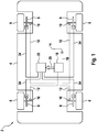
- FIG. 1 shows a schematic view of a vehicle 2 with a driving dynamics control known per se. Details of this vehicle dynamics control can be found, for example, in the DE 10 2011 080 789 A1 be removed.
- the vehicle 2 comprises a chassis 4 and four wheels 6. Each wheel 6 can be slowed down relative to the chassis 4 by means of a brake 8 fixedly attached to the chassis 4 in order to slow down a movement of the vehicle 2 on a road (not shown further).
- ABS anti-lock braking system
- ESP electronic stability program
- the vehicle 2 has speed sensors 10 on the wheels 6 for this purpose, which detect a speed 12 of the wheels 6. Furthermore, the vehicle 2 has an inertial sensor 14, which records the driving dynamics 16 of the vehicle 2, from which, for example, a pitch rate, a roll rate, a yaw rate, a lateral acceleration, a longitudinal acceleration and / or a vertical acceleration can be output in a manner known per se to the person skilled in the art ,
- a controller 18 can determine in a manner known to the person skilled in the art whether the vehicle 2 is sliding on the road or even deviates from the above-mentioned predetermined trajectory and respond to it with a controller output signal 20 known per se.
- the controller output signal 20 can then be used by an actuating device 22 to control actuators, such as the brakes 8, by means of actuating signals 24, which react to the slipping and the deviation from the predetermined trajectory in a manner known per se.
- the present invention is to be clarified, even if the present invention can be implemented on any electronic devices and in particular on any sensors, such as magnetic field sensors, acceleration sensors, rotation rate sensors, structure-borne noise sensors or temperature sensors.
- sensors such as magnetic field sensors, acceleration sensors, rotation rate sensors, structure-borne noise sensors or temperature sensors.
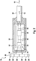
- FIG. 2 Reference is made to a schematic view of the speed sensor 10 in the vehicle 2 of FIG Fig. 1 shows.
- the speed sensor 10 is designed as an active speed sensor 10, in the context of which a magnetic field 30 is emitted by an encoder disk 26 which is connected to one of the wheels 6 in a rotationally fixed manner and which is composed of a plurality of magnetic poles 28.
- the magnetic field 30 penetrates a sensor 34 housed in a housing 32, which is connected via a signal conditioning circuit 36 to a data cable 38, via which the speed 12 can be transmitted to the controller 18.
- the sensor 34, the signal conditioning circuit 36 and the data cable 38 can be wired to one another via wirings 40, for example in the form of a lead frame.
- a shielding plate 42 can be arranged to the electromagnetic To increase the compatibility of the speed sensor 10.
- the speed sensor 10 When used in the aforementioned vehicle 2, it is particularly important for the high durability of the speed sensor 10 to be as tight as possible against the ingress of moisture. Precisely because the speed sensor 10 is installed on the wheel 6, which can throw off a not inconsiderable amount of dirt and moisture while the vehicle 2 is traveling, the sealing against penetrating moisture is of very great importance, which prevents, for example, the wiring 40 from corroding and is interrupted to one
- the sensor circuit 44 of the speed sensor 10, comprising the sensor 34 and the signal evaluation circuit 36, is encased in the following manner with a protective compound forming the housing 32.
- Fig. 3a the electronic assembly 44 without the housing 32 is shown inserted into a tool 45 for the primary shaping of the housing 32.
- the wiring 40 is designed as the above-mentioned lead frame, on which the sensor 34 and the signal evaluation circuit 36 are mechanically held and electrically wired. In order to support the detection of the magnetic field 30, the sensor 34 is bent.
- the master mold 45 is supplemented by further parts, which together form a master mold space 47, which is shown in FIG Fig. 3a opened and is therefore only partially shown.
- the protective compound forming the housing 32 is then introduced into this master mold space 48.
- Any plastic material can be used as a protective mass, the primary molding process being based on the plastic material used. If, for example, a thermoplastic is used as the plastic material, the primary molding process can be an injection molding process.
- the sensor circuit 44 encased in the housing 32 can then be held in a tool 50 by a holding pin 50 and inserted in a further protective compound 54, a so-called overmold.
- the protective effect of the housing 32 and the further protective compound 54 against the ingress of moisture can diminish over time due to wear and other signs of aging, so that it cannot be permanently ensured that no moisture penetrates between the housing 32 and the sensor circuit 44.
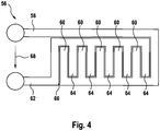
- the present embodiment attacks with the suggestion, for example, between the sensor circuit 44 and the housing 32 Fig. 4 Arrange shown moisture sensor 56, which detects moisture penetrating between the sensor circuit 44 and the housing 32.
- the moisture measuring sensor 56 can be of any design and can be arranged in the sensor 10 as long as it is arranged in such a way that the aforementioned moisture is detected.
- the moisture sensor 56 should be on the surface of the sensor 34 and / or the surface the signal processing circuit 36 can be arranged to keep the space requirement as small as possible.
- existing structures could also be used to arrange the moisture measuring sensor 56, which structures have been placed on the surface of the sensor circuit 44 during production or for other reasons, for example, and which are not used functionally during the normal operation of the sensor 10.
- the moisture measuring sensor 56 can be made from a first comb electrode 58 with a plurality of finger lines 60 and a second comb electrode 62 also with a plurality of finger lines 64.
- the finger lines 60 of the first comb electrode 58 engage in the finger lines 64 of the second comb electrode 62, as a result of which a correspondingly elongated air gap 66 between the two comb electrodes 58, 62 is achieved.
- the two comb electrodes 58, 62 can also wrap around one another, as a result of which, for example, a spiral-shaped air gap 66 is formed, which is also elongated.
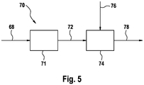
- FIG. 5 Reference schematically an evaluation device 70 for the to the Moisture measuring sensor 56 applied voltage 68, which is dependent on the electrical resistance between the comb electrodes 58, 62 and thus on the moisture.
- the voltage 68 thus represents a monitoring signal with which the moisture between the sensor circuit 44 and the housing 32 can be monitored.
- the voltage 68 is first detected using a voltage measuring device 70.
- the detected voltage 72 can then be compared in a comparison device 74 with a predetermined condition 76, which should be dependent on a predetermined degree of humidity, which may occur between the sensor circuit 44 and the housing 32 at the maximum. Since the moisture lowers the electrical resistance and the capacitance between the two comb electrodes 58, 62, the predetermined condition 76 can be implemented, for example, as a minimum voltage, below which the voltage 68 must not fall.
- the comparison device 74 can output an error 78, which indicates excessive moisture between the sensor circuit 44 and the housing 32. There can be any reaction to this error in vehicle 2.
- One possibility would be to convert the vehicle 2 into a fault mode of operation, in which, for example, the maximum speed of the vehicle is reduced to a predetermined maximum.
Landscapes
- Physics & Mathematics (AREA)
- General Physics & Mathematics (AREA)
- Investigating Or Analyzing Materials By The Use Of Electric Means (AREA)
Claims (8)
- Capteur (10) destiné à acquérir une grandeur de mesure physique avec un diagramme de transmetteur (30), comprenant :- un circuit de capteur (44) destiné à acquérir le diagramme de transmetteur (30) et à délivrer un signal de capteur (12) dépendant de la grandeur de mesure physique,- un boîtier (32) dans lequel est logé le circuit de capteur (44) et- un enregistreur de mesure d'humidité (56) entre le circuit de capteur (44) et le boîtier (32), lequel est conçu pour générer un signal de surveillance (68) qui est dépendant de l'humidité qui pénètre entre le circuit de capteur (44) et le boîtier (32),
le circuit de capteur (44) comportant un enregistreur de mesure (34) destiné à convertir le diagramme de transmetteur (30) en un signal de transmetteur et un circuit de traitement de signal (36) destiné à délivrer le signal de capteur (12) en se basant sur le signal de transmetteur, et l'enregistreur de mesure d'humidité (56) étant disposé sur une surface de l'enregistreur de mesure (34) et/ou du circuit de traitement de signal (36). - Capteur (10) selon la revendication 1, l'enregistreur de mesure d'humidité (56) étant un enregistreur de mesure résistif ayant une première électrode (58) et une deuxième électrode (62) isolée électriquement de la première électrode (58), et une résistance électrique entre les deux électrodes (58, 62) étant dépendante de l'humidité à acquérir.
- Capteur (10) selon la revendication 2, les deux électrodes (58, 62) étant des électrodes en peigne qui s'engrène l'une dans l'autre.
- Capteur (10) selon l'une des revendications précédentes, le diagramme de transmetteur (30) étant dépendant d'une vitesse de rotation d'une roue (6) sur un véhicule (2) et le circuit de capteur (44) étant conçu pour délivrer, en tant que signal de capteur (12), un signal dépendant de la vitesse de rotation.
- Capteur (10) selon l'une des revendications précédentes, le boîtier (32) étant une masse de protection qui enveloppe le circuit de capteur (44).
- Procédé de surveillance d'un capteur (10) selon l'une des revendications précédentes, comprenant :- l'acquisition du signal de surveillance (68),- la délivrance d'un défaut (78) lorsque le signal de surveillance (68) remplit une condition prédéterminée (76), laquelle est dépendante d'un degré d'humidité prédéterminé entre le circuit de capteur (44) et le boîtier (32).
- Procédé selon la revendication 6, le capteur (10) étant installé dans un véhicule (2) et le véhicule (2) étant transféré dans un mode de fonctionnement avec défaut en se basant sur le défaut (78) délivré.
- Véhicule (2), comprenant un châssis (4) porté sur au moins une roue (6), un élément transmetteur (26) relié à la roue (6), lequel est conçu pour délivrer un diagramme de transmetteur (30) qui tourne avec la roue (6), un capteur (10) selon l'une des revendications 1 à 5 destiné à délivrer le signal de capteur (12) en se basant sur le diagramme de transmetteur (26) et un arrangement de commande (70) destiné à délivrer le signal de surveillance (68) en se basant sur l'humidité ayant pénétré entre le circuit de capteur (44) et le boîtier (32) .
Applications Claiming Priority (2)
| Application Number | Priority Date | Filing Date | Title |
|---|---|---|---|
| DE102014218711.7A DE102014218711A1 (de) | 2014-09-17 | 2014-09-17 | Feuchtigkeitserfassung innerhalb eines Sensors |
| PCT/EP2015/069569 WO2016041750A1 (fr) | 2014-09-17 | 2015-08-26 | Détection d'humidité au sein d'un capteur |
Publications (2)
| Publication Number | Publication Date |
|---|---|
| EP3194897A1 EP3194897A1 (fr) | 2017-07-26 |
| EP3194897B1 true EP3194897B1 (fr) | 2019-12-25 |
Family
ID=54035227
Family Applications (1)
| Application Number | Title | Priority Date | Filing Date |
|---|---|---|---|
| EP15757214.0A Active EP3194897B1 (fr) | 2014-09-17 | 2015-08-26 | Détection d'humidité au sein d'un capteur |
Country Status (4)
| Country | Link |
|---|---|
| EP (1) | EP3194897B1 (fr) |
| CN (1) | CN208059920U (fr) |
| DE (1) | DE102014218711A1 (fr) |
| WO (1) | WO2016041750A1 (fr) |
Families Citing this family (4)
| Publication number | Priority date | Publication date | Assignee | Title |
|---|---|---|---|---|
| DE102016208782A1 (de) * | 2016-05-20 | 2017-11-23 | Continental Teves Ag & Co. Ohg | Verfahren zum Ummanteln einer elektrischen Einheit und elektrisches Bauelement |
| DE102018202228A1 (de) * | 2018-02-14 | 2019-08-14 | Ford Global Technologies, Llc | Verfahren zum Betrieb eines Kraftfahrzeugs mit zumindest einer Raddrehzahlsensorbaugruppe |
| US11002582B2 (en) | 2018-09-28 | 2021-05-11 | Rosemount Inc. | Process transmitter with thermal fluid detection for decreasing damage to the process transmitter components |
| CN115200748B (zh) * | 2022-09-15 | 2022-12-02 | 深圳市景新浩科技有限公司 | 基于智能电子体温计状态测量控制系统 |
Family Cites Families (15)
| Publication number | Priority date | Publication date | Assignee | Title |
|---|---|---|---|---|
| US3943557A (en) * | 1974-02-19 | 1976-03-09 | Plessey Incorporated | Semiconductor package with integral hermeticity detector |
| US4224565A (en) * | 1978-06-05 | 1980-09-23 | Bell Telephone Laboratories, Incorporated | Moisture level determination in sealed packages |
| JPS6151535A (ja) * | 1984-08-22 | 1986-03-14 | Sharp Corp | 圧力センサ |
| AT399787B (de) * | 1992-09-08 | 1995-07-25 | Tartsch Erich | Überwachungsgerät zur überwachung der geräteumgebung auf feuchte oder trockenheit |
| US5606264A (en) * | 1995-04-21 | 1997-02-25 | Licari; James J. | Moisture sensor for electronic modules |
| DE10146949A1 (de) | 2000-11-22 | 2002-06-06 | Continental Teves Ag & Co Ohg | Aktiver Magnetsensor für elektronische Bremssysteme |
| DE10120580A1 (de) * | 2001-04-26 | 2002-11-07 | Siemens Ag | Sensor zur Messung eines Drehmomentes an einer rotierenden Welle |
| US6997043B2 (en) * | 2002-08-15 | 2006-02-14 | The Boeing Company | Integration of atmospheric intrusion sensors in electronic component packages |
| DE102006030312A1 (de) * | 2006-06-30 | 2008-01-03 | Schaeffler Kg | Sensoreinheit für ein Radsatzlager |
| ATE513210T1 (de) * | 2006-07-18 | 2011-07-15 | Roche Diagnostics Gmbh | Bauraumoptimiertes tragbares messsystem |
| DE102007005899A1 (de) * | 2007-02-01 | 2008-08-07 | Endress + Hauser Wetzer Gmbh + Co Kg | Vorrichtung zur Bestimmung und/oder Überwachung einer Prozessgröße |
| DE202007018944U1 (de) * | 2007-09-24 | 2009-11-19 | Asm Automation Sensorik Messtechnik Gmbh | Winkelsensor |
| DE102008064046A1 (de) | 2008-10-02 | 2010-04-08 | Continental Teves Ag & Co. Ohg | Verfahren zur Herstellung eines Geschwindigkeits-Sensorelementes |
| DE102011080789B4 (de) | 2010-08-10 | 2022-11-10 | Continental Automotive Technologies GmbH | Verfahren und System zur Regelung der Fahrstabilität |
| DE102012215235A1 (de) * | 2012-08-28 | 2013-05-23 | Robert Bosch Gmbh | Sensorbauteil |
-
2014
- 2014-09-17 DE DE102014218711.7A patent/DE102014218711A1/de not_active Withdrawn
-
2015
- 2015-08-26 WO PCT/EP2015/069569 patent/WO2016041750A1/fr not_active Ceased
- 2015-08-26 CN CN201590000972.9U patent/CN208059920U/zh not_active Expired - Lifetime
- 2015-08-26 EP EP15757214.0A patent/EP3194897B1/fr active Active
Non-Patent Citations (1)
| Title |
|---|
| None * |
Also Published As
| Publication number | Publication date |
|---|---|
| EP3194897A1 (fr) | 2017-07-26 |
| CN208059920U (zh) | 2018-11-06 |
| DE102014218711A1 (de) | 2016-03-17 |
| WO2016041750A1 (fr) | 2016-03-24 |
Similar Documents
| Publication | Publication Date | Title |
|---|---|---|
| DE102010034129B4 (de) | Verfahren zum Betreiben einer Reifendrucküberwachungseinheit | |
| EP3046816B1 (fr) | Procédé de surveillance d'une voie de transmission | |
| EP3074730B1 (fr) | Méthode de fabrication d'un capteur par maintien de la pièce moulée par injection intermédiaire | |
| EP3194897B1 (fr) | Détection d'humidité au sein d'un capteur | |
| WO2012100869A1 (fr) | Agencement d'une unité de captage de pression de gonflage de pneumatique | |
| DE102013217888B4 (de) | Elektronische Vorrichtung und Verfahren zur Herstellung einer elektronischen Vorrichtung | |
| EP3084354B1 (fr) | Assemblage mécanique surdimensionné pour capteur de vitesse de rotation | |
| EP3167253B1 (fr) | Découplage de vibration de capteurs | |
| WO2016005609A2 (fr) | Détecteur spécifique au client réalisé par triple moulage | |
| DE102013225806A1 (de) | Direktes Vermessen eines Stützfeldes in einem Drehzahlsensor | |
| EP2728752B1 (fr) | Unité de détection électronique pour l'enregistrement d'un actionnement sans contact d'une porte ou d'un clapet sur un véhicule automobile | |
| DE102014207766A1 (de) | 3-Achsen-Inertialsensor mit 2-Achsen-Inertialsensor überwachen | |
| WO2016005201A1 (fr) | Capteur pourvu d'une anode sacrificielle | |
| DE102016201204A1 (de) | Sensoren mit vergossener Leiterplatte, in der elektrische Komponenten eingebettet sind | |
| EP2773586B1 (fr) | Élément micromécanique, composant muni d'un élément micromécanique et procédé de fabrication d'un composant | |
| DE102013217879B4 (de) | Verfahren zum Überwachen einer Übertragungsstrecke | |
| DE102013217883A1 (de) | Verfahren zum Überwachen eines Drehzahlsensors | |
| DE102015206299B4 (de) | Über Leiterplatte auf Leadframe verschaltete Sensorschaltung | |
| EP4183664B1 (fr) | Système d'arrêt en cascade de l'entrée de liquide dans un système de direction d'un véhicule | |
| EP2759419A1 (fr) | Capteur et matrice de capteur | |
| DE102015207533A1 (de) | Schirmung als Silikonvergusshalter | |
| DE102014213590A1 (de) | Kundenspezifischer Adapter für Standardsensor | |
| DE102014216855A1 (de) | Radträger sowie Verfahren zur Montage eines Bremsenblechs an einen Radträger | |
| DE102014210523A1 (de) | Spannungsarmes Verkleben von Sensorchips | |
| DE102008041627A1 (de) | Verfahren und Vorrichtung zur Ermittlung von Feuchtigkeit |
Legal Events
| Date | Code | Title | Description |
|---|---|---|---|
| STAA | Information on the status of an ep patent application or granted ep patent |
Free format text: STATUS: THE INTERNATIONAL PUBLICATION HAS BEEN MADE |
|
| PUAI | Public reference made under article 153(3) epc to a published international application that has entered the european phase |
Free format text: ORIGINAL CODE: 0009012 |
|
| STAA | Information on the status of an ep patent application or granted ep patent |
Free format text: STATUS: REQUEST FOR EXAMINATION WAS MADE |
|
| 17P | Request for examination filed |
Effective date: 20170418 |
|
| AK | Designated contracting states |
Kind code of ref document: A1 Designated state(s): AL AT BE BG CH CY CZ DE DK EE ES FI FR GB GR HR HU IE IS IT LI LT LU LV MC MK MT NL NO PL PT RO RS SE SI SK SM TR |
|
| AX | Request for extension of the european patent |
Extension state: BA ME |
|
| DAV | Request for validation of the european patent (deleted) | ||
| DAX | Request for extension of the european patent (deleted) | ||
| RAP1 | Party data changed (applicant data changed or rights of an application transferred) |
Owner name: CONTINENTAL TEVES AG & CO. OHG |
|
| STAA | Information on the status of an ep patent application or granted ep patent |
Free format text: STATUS: EXAMINATION IS IN PROGRESS |
|
| 17Q | First examination report despatched |
Effective date: 20181205 |
|
| GRAP | Despatch of communication of intention to grant a patent |
Free format text: ORIGINAL CODE: EPIDOSNIGR1 |
|
| STAA | Information on the status of an ep patent application or granted ep patent |
Free format text: STATUS: GRANT OF PATENT IS INTENDED |
|
| INTG | Intention to grant announced |
Effective date: 20190724 |
|
| GRAS | Grant fee paid |
Free format text: ORIGINAL CODE: EPIDOSNIGR3 |
|
| GRAA | (expected) grant |
Free format text: ORIGINAL CODE: 0009210 |
|
| STAA | Information on the status of an ep patent application or granted ep patent |
Free format text: STATUS: THE PATENT HAS BEEN GRANTED |
|
| AK | Designated contracting states |
Kind code of ref document: B1 Designated state(s): AL AT BE BG CH CY CZ DE DK EE ES FI FR GB GR HR HU IE IS IT LI LT LU LV MC MK MT NL NO PL PT RO RS SE SI SK SM TR |
|
| REG | Reference to a national code |
Ref country code: GB Ref legal event code: FG4D Free format text: NOT ENGLISH |
|
| REG | Reference to a national code |
Ref country code: CH Ref legal event code: EP |
|
| REG | Reference to a national code |
Ref country code: AT Ref legal event code: REF Ref document number: 1217623 Country of ref document: AT Kind code of ref document: T Effective date: 20200115 |
|
| REG | Reference to a national code |
Ref country code: DE Ref legal event code: R096 Ref document number: 502015011330 Country of ref document: DE |
|
| REG | Reference to a national code |
Ref country code: IE Ref legal event code: FG4D Free format text: LANGUAGE OF EP DOCUMENT: GERMAN |
|
| REG | Reference to a national code |
Ref country code: NL Ref legal event code: MP Effective date: 20191225 |
|
| PG25 | Lapsed in a contracting state [announced via postgrant information from national office to epo] |
Ref country code: SE Free format text: LAPSE BECAUSE OF FAILURE TO SUBMIT A TRANSLATION OF THE DESCRIPTION OR TO PAY THE FEE WITHIN THE PRESCRIBED TIME-LIMIT Effective date: 20191225 Ref country code: LV Free format text: LAPSE BECAUSE OF FAILURE TO SUBMIT A TRANSLATION OF THE DESCRIPTION OR TO PAY THE FEE WITHIN THE PRESCRIBED TIME-LIMIT Effective date: 20191225 Ref country code: LT Free format text: LAPSE BECAUSE OF FAILURE TO SUBMIT A TRANSLATION OF THE DESCRIPTION OR TO PAY THE FEE WITHIN THE PRESCRIBED TIME-LIMIT Effective date: 20191225 Ref country code: NO Free format text: LAPSE BECAUSE OF FAILURE TO SUBMIT A TRANSLATION OF THE DESCRIPTION OR TO PAY THE FEE WITHIN THE PRESCRIBED TIME-LIMIT Effective date: 20200325 Ref country code: GR Free format text: LAPSE BECAUSE OF FAILURE TO SUBMIT A TRANSLATION OF THE DESCRIPTION OR TO PAY THE FEE WITHIN THE PRESCRIBED TIME-LIMIT Effective date: 20200326 Ref country code: BG Free format text: LAPSE BECAUSE OF FAILURE TO SUBMIT A TRANSLATION OF THE DESCRIPTION OR TO PAY THE FEE WITHIN THE PRESCRIBED TIME-LIMIT Effective date: 20200325 Ref country code: FI Free format text: LAPSE BECAUSE OF FAILURE TO SUBMIT A TRANSLATION OF THE DESCRIPTION OR TO PAY THE FEE WITHIN THE PRESCRIBED TIME-LIMIT Effective date: 20191225 |
|
| REG | Reference to a national code |
Ref country code: LT Ref legal event code: MG4D |
|
| PG25 | Lapsed in a contracting state [announced via postgrant information from national office to epo] |
Ref country code: RS Free format text: LAPSE BECAUSE OF FAILURE TO SUBMIT A TRANSLATION OF THE DESCRIPTION OR TO PAY THE FEE WITHIN THE PRESCRIBED TIME-LIMIT Effective date: 20191225 Ref country code: HR Free format text: LAPSE BECAUSE OF FAILURE TO SUBMIT A TRANSLATION OF THE DESCRIPTION OR TO PAY THE FEE WITHIN THE PRESCRIBED TIME-LIMIT Effective date: 20191225 |
|
| PG25 | Lapsed in a contracting state [announced via postgrant information from national office to epo] |
Ref country code: AL Free format text: LAPSE BECAUSE OF FAILURE TO SUBMIT A TRANSLATION OF THE DESCRIPTION OR TO PAY THE FEE WITHIN THE PRESCRIBED TIME-LIMIT Effective date: 20191225 |
|
| PG25 | Lapsed in a contracting state [announced via postgrant information from national office to epo] |
Ref country code: RO Free format text: LAPSE BECAUSE OF FAILURE TO SUBMIT A TRANSLATION OF THE DESCRIPTION OR TO PAY THE FEE WITHIN THE PRESCRIBED TIME-LIMIT Effective date: 20191225 Ref country code: EE Free format text: LAPSE BECAUSE OF FAILURE TO SUBMIT A TRANSLATION OF THE DESCRIPTION OR TO PAY THE FEE WITHIN THE PRESCRIBED TIME-LIMIT Effective date: 20191225 Ref country code: PT Free format text: LAPSE BECAUSE OF FAILURE TO SUBMIT A TRANSLATION OF THE DESCRIPTION OR TO PAY THE FEE WITHIN THE PRESCRIBED TIME-LIMIT Effective date: 20200520 Ref country code: CZ Free format text: LAPSE BECAUSE OF FAILURE TO SUBMIT A TRANSLATION OF THE DESCRIPTION OR TO PAY THE FEE WITHIN THE PRESCRIBED TIME-LIMIT Effective date: 20191225 Ref country code: NL Free format text: LAPSE BECAUSE OF FAILURE TO SUBMIT A TRANSLATION OF THE DESCRIPTION OR TO PAY THE FEE WITHIN THE PRESCRIBED TIME-LIMIT Effective date: 20191225 |
|
| PG25 | Lapsed in a contracting state [announced via postgrant information from national office to epo] |
Ref country code: SK Free format text: LAPSE BECAUSE OF FAILURE TO SUBMIT A TRANSLATION OF THE DESCRIPTION OR TO PAY THE FEE WITHIN THE PRESCRIBED TIME-LIMIT Effective date: 20191225 Ref country code: IS Free format text: LAPSE BECAUSE OF FAILURE TO SUBMIT A TRANSLATION OF THE DESCRIPTION OR TO PAY THE FEE WITHIN THE PRESCRIBED TIME-LIMIT Effective date: 20200425 Ref country code: SM Free format text: LAPSE BECAUSE OF FAILURE TO SUBMIT A TRANSLATION OF THE DESCRIPTION OR TO PAY THE FEE WITHIN THE PRESCRIBED TIME-LIMIT Effective date: 20191225 |
|
| REG | Reference to a national code |
Ref country code: DE Ref legal event code: R097 Ref document number: 502015011330 Country of ref document: DE |
|
| PG25 | Lapsed in a contracting state [announced via postgrant information from national office to epo] |
Ref country code: ES Free format text: LAPSE BECAUSE OF FAILURE TO SUBMIT A TRANSLATION OF THE DESCRIPTION OR TO PAY THE FEE WITHIN THE PRESCRIBED TIME-LIMIT Effective date: 20191225 Ref country code: DK Free format text: LAPSE BECAUSE OF FAILURE TO SUBMIT A TRANSLATION OF THE DESCRIPTION OR TO PAY THE FEE WITHIN THE PRESCRIBED TIME-LIMIT Effective date: 20191225 |
|
| PLBE | No opposition filed within time limit |
Free format text: ORIGINAL CODE: 0009261 |
|
| STAA | Information on the status of an ep patent application or granted ep patent |
Free format text: STATUS: NO OPPOSITION FILED WITHIN TIME LIMIT |
|
| PG25 | Lapsed in a contracting state [announced via postgrant information from national office to epo] |
Ref country code: SI Free format text: LAPSE BECAUSE OF FAILURE TO SUBMIT A TRANSLATION OF THE DESCRIPTION OR TO PAY THE FEE WITHIN THE PRESCRIBED TIME-LIMIT Effective date: 20191225 |
|
| 26N | No opposition filed |
Effective date: 20200928 |
|
| PG25 | Lapsed in a contracting state [announced via postgrant information from national office to epo] |
Ref country code: IT Free format text: LAPSE BECAUSE OF FAILURE TO SUBMIT A TRANSLATION OF THE DESCRIPTION OR TO PAY THE FEE WITHIN THE PRESCRIBED TIME-LIMIT Effective date: 20191225 |
|
| PG25 | Lapsed in a contracting state [announced via postgrant information from national office to epo] |
Ref country code: PL Free format text: LAPSE BECAUSE OF FAILURE TO SUBMIT A TRANSLATION OF THE DESCRIPTION OR TO PAY THE FEE WITHIN THE PRESCRIBED TIME-LIMIT Effective date: 20191225 |
|
| PG25 | Lapsed in a contracting state [announced via postgrant information from national office to epo] |
Ref country code: MC Free format text: LAPSE BECAUSE OF FAILURE TO SUBMIT A TRANSLATION OF THE DESCRIPTION OR TO PAY THE FEE WITHIN THE PRESCRIBED TIME-LIMIT Effective date: 20191225 |
|
| REG | Reference to a national code |
Ref country code: CH Ref legal event code: PL |
|
| PG25 | Lapsed in a contracting state [announced via postgrant information from national office to epo] |
Ref country code: LU Free format text: LAPSE BECAUSE OF NON-PAYMENT OF DUE FEES Effective date: 20200826 Ref country code: LI Free format text: LAPSE BECAUSE OF NON-PAYMENT OF DUE FEES Effective date: 20200831 Ref country code: CH Free format text: LAPSE BECAUSE OF NON-PAYMENT OF DUE FEES Effective date: 20200831 |
|
| REG | Reference to a national code |
Ref country code: BE Ref legal event code: MM Effective date: 20200831 |
|
| PG25 | Lapsed in a contracting state [announced via postgrant information from national office to epo] |
Ref country code: IE Free format text: LAPSE BECAUSE OF NON-PAYMENT OF DUE FEES Effective date: 20200826 Ref country code: BE Free format text: LAPSE BECAUSE OF NON-PAYMENT OF DUE FEES Effective date: 20200831 |
|
| REG | Reference to a national code |
Ref country code: AT Ref legal event code: MM01 Ref document number: 1217623 Country of ref document: AT Kind code of ref document: T Effective date: 20200826 |
|
| PG25 | Lapsed in a contracting state [announced via postgrant information from national office to epo] |
Ref country code: AT Free format text: LAPSE BECAUSE OF NON-PAYMENT OF DUE FEES Effective date: 20200826 |
|
| PG25 | Lapsed in a contracting state [announced via postgrant information from national office to epo] |
Ref country code: TR Free format text: LAPSE BECAUSE OF FAILURE TO SUBMIT A TRANSLATION OF THE DESCRIPTION OR TO PAY THE FEE WITHIN THE PRESCRIBED TIME-LIMIT Effective date: 20191225 Ref country code: MT Free format text: LAPSE BECAUSE OF FAILURE TO SUBMIT A TRANSLATION OF THE DESCRIPTION OR TO PAY THE FEE WITHIN THE PRESCRIBED TIME-LIMIT Effective date: 20191225 Ref country code: CY Free format text: LAPSE BECAUSE OF FAILURE TO SUBMIT A TRANSLATION OF THE DESCRIPTION OR TO PAY THE FEE WITHIN THE PRESCRIBED TIME-LIMIT Effective date: 20191225 |
|
| PG25 | Lapsed in a contracting state [announced via postgrant information from national office to epo] |
Ref country code: MK Free format text: LAPSE BECAUSE OF FAILURE TO SUBMIT A TRANSLATION OF THE DESCRIPTION OR TO PAY THE FEE WITHIN THE PRESCRIBED TIME-LIMIT Effective date: 20191225 |
|
| REG | Reference to a national code |
Ref country code: DE Ref legal event code: R081 Ref document number: 502015011330 Country of ref document: DE Owner name: CONTINENTAL AUTOMOTIVE TECHNOLOGIES GMBH, DE Free format text: FORMER OWNER: CONTINENTAL TEVES AG & CO. OHG, 60488 FRANKFURT, DE Ref country code: DE Ref legal event code: R081 Ref document number: 502015011330 Country of ref document: DE Owner name: AUMOVIO GERMANY GMBH, DE Free format text: FORMER OWNER: CONTINENTAL TEVES AG & CO. OHG, 60488 FRANKFURT, DE |
|
| REG | Reference to a national code |
Ref country code: GB Ref legal event code: 732E Free format text: REGISTERED BETWEEN 20230216 AND 20230222 |
|
| PGFP | Annual fee paid to national office [announced via postgrant information from national office to epo] |
Ref country code: GB Payment date: 20230822 Year of fee payment: 9 |
|
| PGFP | Annual fee paid to national office [announced via postgrant information from national office to epo] |
Ref country code: FR Payment date: 20230825 Year of fee payment: 9 |
|
| REG | Reference to a national code |
Ref country code: DE Ref legal event code: R081 Ref document number: 502015011330 Country of ref document: DE Owner name: CONTINENTAL AUTOMOTIVE TECHNOLOGIES GMBH, DE Free format text: FORMER OWNER: CONTINENTAL AUTOMOTIVE TECHNOLOGIES GMBH, 30165 HANNOVER, DE Ref country code: DE Ref legal event code: R081 Ref document number: 502015011330 Country of ref document: DE Owner name: AUMOVIO GERMANY GMBH, DE Free format text: FORMER OWNER: CONTINENTAL AUTOMOTIVE TECHNOLOGIES GMBH, 30165 HANNOVER, DE |
|
| GBPC | Gb: european patent ceased through non-payment of renewal fee |
Effective date: 20240826 |
|
| PG25 | Lapsed in a contracting state [announced via postgrant information from national office to epo] |
Ref country code: GB Free format text: LAPSE BECAUSE OF NON-PAYMENT OF DUE FEES Effective date: 20240826 |
|
| PG25 | Lapsed in a contracting state [announced via postgrant information from national office to epo] |
Ref country code: FR Free format text: LAPSE BECAUSE OF NON-PAYMENT OF DUE FEES Effective date: 20240831 |
|
| PGFP | Annual fee paid to national office [announced via postgrant information from national office to epo] |
Ref country code: DE Payment date: 20250831 Year of fee payment: 11 |
|
| REG | Reference to a national code |
Ref country code: DE Ref legal event code: R081 Ref document number: 502015011330 Country of ref document: DE Owner name: AUMOVIO GERMANY GMBH, DE Free format text: FORMER OWNER: CONTINENTAL AUTOMOTIVE TECHNOLOGIES GMBH, 30175 HANNOVER, DE |