EP2778331A1 - Scharnieranordnung - Google Patents
Scharnieranordnung Download PDFInfo
- Publication number
- EP2778331A1 EP2778331A1 EP13158652.1A EP13158652A EP2778331A1 EP 2778331 A1 EP2778331 A1 EP 2778331A1 EP 13158652 A EP13158652 A EP 13158652A EP 2778331 A1 EP2778331 A1 EP 2778331A1
- Authority
- EP
- European Patent Office
- Prior art keywords
- mounting plate
- portions
- hinge assembly
- mounting
- cover
- Prior art date
- Legal status (The legal status is an assumption and is not a legal conclusion. Google has not performed a legal analysis and makes no representation as to the accuracy of the status listed.)
- Withdrawn
Links
Images
Classifications
-
- E—FIXED CONSTRUCTIONS
- E05—LOCKS; KEYS; WINDOW OR DOOR FITTINGS; SAFES
- E05D—HINGES OR SUSPENSION DEVICES FOR DOORS, WINDOWS OR WINGS
- E05D11/00—Additional features or accessories of hinges
- E05D11/0018—Anti-tamper devices
-
- E—FIXED CONSTRUCTIONS
- E05—LOCKS; KEYS; WINDOW OR DOOR FITTINGS; SAFES
- E05D—HINGES OR SUSPENSION DEVICES FOR DOORS, WINDOWS OR WINGS
- E05D11/00—Additional features or accessories of hinges
- E05D11/0054—Covers, e.g. for protection
-
- E—FIXED CONSTRUCTIONS
- E05—LOCKS; KEYS; WINDOW OR DOOR FITTINGS; SAFES
- E05D—HINGES OR SUSPENSION DEVICES FOR DOORS, WINDOWS OR WINGS
- E05D7/00—Hinges or pivots of special construction
- E05D7/04—Hinges adjustable relative to the wing or the frame
- E05D7/043—Hinges adjustable relative to the wing or the frame by means of dowel attachments
- E05D2007/0446—Hinges adjustable relative to the wing or the frame by means of dowel attachments with threaded bolts fixedly mounted on the hinge part
-
- E—FIXED CONSTRUCTIONS
- E05—LOCKS; KEYS; WINDOW OR DOOR FITTINGS; SAFES
- E05D—HINGES OR SUSPENSION DEVICES FOR DOORS, WINDOWS OR WINGS
- E05D7/00—Hinges or pivots of special construction
- E05D7/04—Hinges adjustable relative to the wing or the frame
- E05D2007/0492—Hinges adjustable relative to the wing or the frame in three directions
-
- E—FIXED CONSTRUCTIONS
- E05—LOCKS; KEYS; WINDOW OR DOOR FITTINGS; SAFES
- E05D—HINGES OR SUSPENSION DEVICES FOR DOORS, WINDOWS OR WINGS
- E05D11/00—Additional features or accessories of hinges
- E05D11/0054—Covers, e.g. for protection
- E05D2011/0063—Covers, e.g. for protection for screw-heads or bolt-heads
-
- E—FIXED CONSTRUCTIONS
- E05—LOCKS; KEYS; WINDOW OR DOOR FITTINGS; SAFES
- E05D—HINGES OR SUSPENSION DEVICES FOR DOORS, WINDOWS OR WINGS
- E05D5/00—Construction of single parts, e.g. the parts for attachment
- E05D5/02—Parts for attachment, e.g. flaps
-
- E—FIXED CONSTRUCTIONS
- E05—LOCKS; KEYS; WINDOW OR DOOR FITTINGS; SAFES
- E05D—HINGES OR SUSPENSION DEVICES FOR DOORS, WINDOWS OR WINGS
- E05D5/00—Construction of single parts, e.g. the parts for attachment
- E05D5/10—Pins, sockets or sleeves; Removable pins
- E05D5/12—Securing pins in sockets, movably or not
- E05D5/128—Securing pins in sockets, movably or not the pin having a recess or through-hole engaged by a securing member
-
- E—FIXED CONSTRUCTIONS
- E05—LOCKS; KEYS; WINDOW OR DOOR FITTINGS; SAFES
- E05D—HINGES OR SUSPENSION DEVICES FOR DOORS, WINDOWS OR WINGS
- E05D7/00—Hinges or pivots of special construction
- E05D7/04—Hinges adjustable relative to the wing or the frame
-
- E—FIXED CONSTRUCTIONS
- E05—LOCKS; KEYS; WINDOW OR DOOR FITTINGS; SAFES
- E05D—HINGES OR SUSPENSION DEVICES FOR DOORS, WINDOWS OR WINGS
- E05D7/00—Hinges or pivots of special construction
- E05D7/04—Hinges adjustable relative to the wing or the frame
- E05D7/043—Hinges adjustable relative to the wing or the frame by means of dowel attachments
-
- E—FIXED CONSTRUCTIONS
- E05—LOCKS; KEYS; WINDOW OR DOOR FITTINGS; SAFES
- E05Y—INDEXING SCHEME ASSOCIATED WITH SUBCLASSES E05D AND E05F, RELATING TO CONSTRUCTION ELEMENTS, ELECTRIC CONTROL, POWER SUPPLY, POWER SIGNAL OR TRANSMISSION, USER INTERFACES, MOUNTING OR COUPLING, DETAILS, ACCESSORIES, AUXILIARY OPERATIONS NOT OTHERWISE PROVIDED FOR, APPLICATION THEREOF
- E05Y2201/00—Constructional elements; Accessories therefor
- E05Y2201/10—Covers; Housings
- E05Y2201/11—Covers
-
- E—FIXED CONSTRUCTIONS
- E05—LOCKS; KEYS; WINDOW OR DOOR FITTINGS; SAFES
- E05Y—INDEXING SCHEME ASSOCIATED WITH SUBCLASSES E05D AND E05F, RELATING TO CONSTRUCTION ELEMENTS, ELECTRIC CONTROL, POWER SUPPLY, POWER SIGNAL OR TRANSMISSION, USER INTERFACES, MOUNTING OR COUPLING, DETAILS, ACCESSORIES, AUXILIARY OPERATIONS NOT OTHERWISE PROVIDED FOR, APPLICATION THEREOF
- E05Y2600/00—Mounting or coupling arrangements for elements provided for in this subclass
- E05Y2600/60—Mounting or coupling members; Accessories therefor
- E05Y2600/624—Nuts
-
- E—FIXED CONSTRUCTIONS
- E05—LOCKS; KEYS; WINDOW OR DOOR FITTINGS; SAFES
- E05Y—INDEXING SCHEME ASSOCIATED WITH SUBCLASSES E05D AND E05F, RELATING TO CONSTRUCTION ELEMENTS, ELECTRIC CONTROL, POWER SUPPLY, POWER SIGNAL OR TRANSMISSION, USER INTERFACES, MOUNTING OR COUPLING, DETAILS, ACCESSORIES, AUXILIARY OPERATIONS NOT OTHERWISE PROVIDED FOR, APPLICATION THEREOF
- E05Y2900/00—Application of doors, windows, wings or fittings thereof
- E05Y2900/40—Application of doors, windows, wings or fittings thereof for gates
Definitions
- the present invention relates to a hinge assembly and is more particularly concerned with hinge assemblies for gates.
- Hinge assemblies are known for hanging gates which range from very simple assemblies where there is no adjustment in the hinge assembly to more complex assemblies that provide correct positioning of the gate in three-dimensions.
- One such more complex assembly is described in EP-A-1528202 .
- a hinge mechanism for hanging a gate at an adjustable height on a support comprises a trough-shaped rail member mounted on one of the support and the gate, a mounting plate mountable on the rail member, and an eye bolt mountable in a bracket provided on the other one of the support and the gate and attachable to the mounting plate.
- the rail member includes a sliding element positioned within the trough and to which the mounting plate is mounted, the sliding element providing adjustment in a vertical direction, for example, a direction coincident with, or parallel to, the support or gate to which the rail is mounted.
- the mounting plate includes an elongate transverse slot into which the threaded portion of the eye bolt is inserted and tightened using nuts on either side of the mounting plate, the transverse slot providing adjustment in a horizontal direction, for example, an orthogonal direction relative to the vertical direction, as well as in a depth direction, for example, a direction orthogonal to both the vertical and horizontal directions, by means of the positions of the nuts along the threaded portion of the eye bolt.
- This mechanism provides adjustment for the gate in three orthogonal directions.
- EP-A-1528202 provides correct positioning of a gate with respect to a support on which the gate is mounted, at least a part of the mechanism is exposed and can be tampered with, and even be removed, when the gate is in a closed and locked position to allow access through the gate.
- a hinge assembly for mounting an opening member to a support, one of the opening member and the support having a bracket formed thereon, the hinge assembly comprising:
- a cover By having a cover, added security can be provided as, when the opening member is in a closed and locked position, no access is provided to the nut elements on the eye bolt, in particular to the nut portions thereof, due to the cover being located within the flange portions of the flanged nut elements. Moreover, the flange portions of the flanged nut elements provide a support or wall for the sidewalls of the cover so that these sidewalls cannot be forced outwards to allow access to the nut elements on the eye bolt.
- the other of the opening member and support has a rail member formed thereon, and the hinge assembly further comprises a sliding element mountable within the rail member into which each fixing screw is inserted through the rail member.
- the cover comprises first and second portions substantially parallel to and spaced from one another and a third portion connecting the first and second portions to one another.
- the first, second and third portions may define a channel for encompassing said at least one portion of the mounting plate.
- the channel is both shaped and sized to be retained within the walls defined by the flange portions of the flanged nut elements.
- each of the first and second portions comprises first and second flange portions which are locatable within the walls defined by the flanged portions of the flanged nut elements when assembled over the mounting plate.
- the cover advantageously comprises first and second mounting portions formed integrally with one of the first and second portions, the first and second mounting portions each comprising a hole by means of which the cover is fixed to the mounting plate.
- the cover is deformable from a first configuration to a second configuration to encompass said at least one portion of the mounting plate and to be attached thereto.
- At least one cut-out may be provided in at least one of the first and second portions to allow the cover to deform.
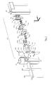
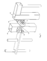
- FIG. 1 an exploded view of a hinge assembly 100 in accordance with the present invention is shown together with a support or post 10 on which a gate 20 is to be mounted.
- the support or post 10 has a bracket 30 to which the hinge assembly 100 is mounted.
- the bracket 30 comprises two mounting plate portions 32, 34 having respective holes 32a, 34a.
- the gate 20 includes a rail member 40 which is welded thereto (not shown for ease of explanation).
- the gate 20 with the rail member 40 welded thereto are galvanised as one component.
- the rail member 40 has an elongate slot 45 which provides adjustment in a direction aligned with the gate, that is, in the y-direction, as will be described in more detail below.
- the hinge assembly 100 comprises an eye bolt 110, a mounting plate 120, a sliding element 130 mountable within the rail member 40 on the gate 20, and a cover 140.
- Fixing screws 150a, 150b are provided for mounting the mounting plate 120 on the gate 20.
- a mounting pin 160 is provided together with washers 170a, 170b, 170c, 170d, a grub screw 180 and a split pin 190 for mounting the eye bolt 110 to the bracket 30.
- Flanged nuts 200a, 200b and associated washers 210a, 210b are provided for mounting the eye bolt 110 to the mounting plate 120.
- the mounting plate 120 is shaped to be mounted on the rail member 45 of the gate 20 and has two holes 122, 124 for receiving fixing screws 150a, 150b as will be described in more detail below.
- the mounting plate 120 also has an elongate slot 126 extending in a direction substantially orthogonal to a line between the holes 122, 124. The elongate slot 126 provides adjustment in the x-direction as shown.
- the sliding element 130 has two tapped holes 132, 134 which have substantially the same spacing as the holes 122, 124 in the mounting plate 120.
- the sliding element 130 is introduced into a space defined by the rail member 40 and the gate 20, and the tapped holes 132, 134 receive the fixing screws 150a, 150a when the mounting plate 120 is mounted on the rail member 40, the fixing screws 150a, 150b passing through the elongate slot 45 and into respective ones of the tapped holes 132, 134.
- the mounting plate 120 can be adjusted in the y-direction before the screws 150a, 150b are tightened within the sliding element 130.
- the eye bolt 110 has an eye portion 112 and a threaded bolt portion 114 extending from the eye portion 112 as shown.
- the eye portion 112 is used to mount the eye bolt 110 to the bracket 30 mounted on the support or post 10.
- a central aperture 112a is provided in the eye portion 112 through which mounting pin 160 is inserted to retain the eye bolt 110 in position with respect to the bracket 30 as will be described in more detail below.
- grub screw 180 and split pin 190 also retain the eye bolt 110 within the bracket 30 with washers 170a, 170b located either side of mounting plate portion 32 and washers 170c, 170d being located either side of mounting plate portion 34.
- Mounting pin 160 has an annular recess or groove 162 and a through hole 164.
- the annular recess or groove 162 receives the grub screw 180 when it is aligned with a hole (not shown) formed in the eye portion 112, the hole extending into the central aperture 112a.
- the engagement of the grub screw 180 with the annular recess or groove 162 retains the mounting pin 160 within the bracket 30 but allows rotation movement of the eye bolt 110 about a longitudinal axis extending through the mounting pin 160.
- the grub screw 180 sits wholly within the hole in the eye portion 112 and can only be removed when the gate 20 is in an open position. As a result, in the normally closed (and locked) position of the gate, the grub screw 180 is not accessible.
- the through hole 164 receives the split pin 190 to lock the mounting pin 160 in the vertical direction, the ends of the split pin 190 being folded back once they are fully through the aperture 164.
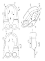
- the cover 140 is shown in more detail in Figures 6 to 13 .
- the cover 140 is shown prior to assembly of the hinge assembly and comprises a top wall portion 140a, a bottom wall portion 140b and a side wall portion 140c.
- the top, bottom and side wall portions 140a, 140b, 140c define a channel into which at least a portion of the mounting plate 120 can be encompassed.
- the top wall portion 140a extends to provide two holes 142, 144 by way of which the cover 140 is secured to the gate 20 as will be described in more detail below.
- the bottom wall portion 140b is not co-extensive with the top wall portion 140a. Cut-outs 146a, 146b are formed in respective ones of the top and bottom wall portions 140a, 140b to allow deformation of the cover 140 so that the holes 142, 144 can be aligned with the holes 122, 124 of the mounting plate 120 and into which the fixing screws 150a, 150b can be inserted for mounting the cover 140 over the mounting plate 120 as will be described in more detail below.
- the cover 140 is shown after assembly of the hinge assembly 100 but with the other components omitted for clarity.
- the top portion 140a is bent to allow the two holes 142, 144 to be more closely spaced and through which the fixing screws 150a, 150b can be inserted, the cut-outs 146a, 146b allowing the bending of the cover 140.
- the cover 140 is manufactured from a single piece of metal, the unfolded shape as shown in the Figures being punched out of a sheet of metal and then folded to the shape shown in Figures 6 to 9 .
- Flange portions 140a', 140a" of the top portion 140a and flange portions 140b', 140b" of the bottom portion 140b forming an angle with respect to one another as shown in Figures 6 to 9 and being substantially parallel when folded as shown in Figures 10 to 13 .
- the flanged nuts 200a and 200b comprise a nut portion 200a', 200b' and a flange portion 200a", 200b".
- Each flange portion 140a', 140a", 140b', 140b" of the cover 140 and each nut portion 200a', 200b' of the flanged nuts 200a, 200b is arranged to be inside the associated flange portion 200a", 200b" of each flanged nut 200a, 200b as will be described in more detail below.
- the eye bolt 110 is assembled to the bracket 30 on the support or post 10. This is achieved by aligning the threaded bolt portion 114 of the eye bolt 110 so that the hole is accessible for insertion of the grub screw 180. Washers 170a, 170b and 170c, 170d are positioned on either side of the eye portion 112 and inserted into the space between the two mounting plate portions 32, 34 of the bracket 30.
- the mounting pin 160 is inserted through the hole 32a in the mounting portion 32, holes in washers 170a, 170b, the central aperture 112a of the eye portion 112, the holes in washers 170c, 170d, and the hole 34a in mounting portion 34.
- the grub screw 180 is then inserted into the hole in the eye portion 112 (not shown) and into the annular recess or groove 162 of the mounting pin 162 and adjusted so that there is still rotational movement of the eye bolt 110 with respect to the bracket 30.
- the split pin 190 is inserted into the through hole 164 in the mounting pin 162. The ends of the split pin 190 are folded back to secure the mounting pin 162 in the vertical direction.
- screw could be used and the through hole 164 in the mounting pin 160 is threaded for receiving the thread of the screw.
- the mounting plate 120 is fixed to the rail member 40 by inserting the sliding element 130 into a space defined by the rail member 40 and the gate 20 and using the fixing screws 150a, 150b to attach the mounting plate to the sliding element 130, the tapped holes 132, 134 being visible through the elongate slot 45 of the rail member 40. Adjustment in the vertical direction, that is, the y-direction, is provided by the relative position of the sliding element 130 with respect to the rail member 40 which is welded to the gate 20.
- the rail member 40 and the sliding element 130 are not essential to the present invention.
- the holes 122, 124 in the mounting plate 120 may comprise slots extending in an orthogonal direction to the elongate transverse slot 126.
- the mounting plate 120 may then be mountable directly onto the gate 20.
- the bracket 30 is formed on the gate 20, the mounting plate 120 may be directly mountable on the support or post 10.
- Flanged nut 200a and its associated washer are mounted on the threaded portion 114 of the eye bolt 110 before the threaded portion 114 is inserted into the elongate slot 126 in the mounting plate 120.
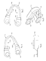
- the flange portion of the flanged nut 200a is arranged to be closer to the eye portion 112 than its associated nut portion and washer 210a. This is shown more clearly in Figure 2 .
- the flanged nut 200b and its associated washer 210b are attached to the free end of the threaded portion 114 after it has been inserted through the elongate slot 126.
- the flange portion of the flanged nut 200b is arranged to be further from the eye portion 112 than its associated nut portion and washer 210b.
- the flange portions of the flanged nuts 200a, 200b effective define walls within which the flange portions 140a', 140a", 140b', 140b" of the top and bottom portions 140a, 140b are located when the cover 140 is mounted over the mounting plate 120. In this way, access to the nut portions 200a', 200b' of the flanged nuts 200a, 200b is prevented by the flanged portions 200a", 200b" of these flanged nuts and by the flange portions of the cover 140.
- the flange portions of the flanged nuts 200a, 200b prevent moreover the flange portions 140a', 140a", 140b', 140b" of the cover 140 to be deformed to allow access for example by an open-end wrench to the nut portions 200a', 200b' of the flanged nuts 200a, 200b.
- the relative positioning of the threaded portion 114 of the eye bolt 110 with respect to the gate 20 provides adjustment in the x-direction. Tightening of the flanged nuts 200a, 200b on the threaded portion 114 of the eye bolt 110 so that the mounting plate 120 is clamped between these two nuts 200a, 200b fixes the eye bolt 110 to the mounting plate 120. As described previously, the flanged nuts 200a, 200b and their associated washers 210a, 210b are positioned on either side of the mounting plate 120. The flanged nuts 200a, 200b have their nut portions 200a', 200b' directed towards the mounting plate 120 and their flange portions 200a", 200b" directed away from the mounting plate 120. The relative positions of the flanged nuts 200a, 200b on the threaded portion 114 of the eye bolt 110 provides adjustment in a direction orthogonal to the elongate slot 126, that is, in the z-direction.
- the adjustment provided by the flanged nuts 200a, 200b also provides adjustment in the x-direction according to the relative position of these flanged nuts 200a, 200b with respect to the holes 122, 124 formed in the mounting plate 120.
- the mounting plate 120 and threaded portion 114 of the eye bolt 110 provide adjustment in both the x- and z-directions.
- the positioning of the mounting plate 120 has been described as being performed before attaching the threaded portion 114 of the eye bolt 110 to the mounting plate 120, it will be appreciated that is it is also possible to attach the mounting plate to the threaded portion 114 of the eye bolt 110 before fixing the mounting plate 120 to the gate 20 as described above.
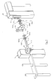
- FIG. 3 illustrates a gate 20 mounted on a support or post 10 prior to the cover 140 being fixed over the mounting plate 120. Either one of the fixing screws 150a, 150b is temporarily removed (or initially not applied yet) so that the top portion 140a of the cover 140 can attached whilst still supporting the weight of the gate 20 in its fully adjusted position, that is, aligned correctly with respect to the support or post 10 in the x-, y and z- directions.
- fixing screw 150a is chosen to be removed, the cover 140 is aligned so that hole 142 is aligned with hole 122 in the mounting plate 120 and the fixing screw 150a is re-inserted and tightened before removing the other fixing screw 150b.
- the cover 140 is deformed so that the hole 144 is aligned with respect to the hole 124 in the mounting plate 120 and the fixing screw 150b re-inserted and tightened.
- the order of removal and re-insertion of the fixing screws 150a, 150b can be reversed.
- the top portion 140a of the cover 140 is located over the flanged nut 200a with the nut portion 200a' of the flanged nut 200a being located between the two flange portions 140a' and 140a" and with the flange portions 140a' and 140a" ( Figures 6 to 13 ) being located adjacent the flange portion 200a" of the flanged nut 200a (engaging preferably this flange portion 200a").
- the bottom portion 140b of the cover 140 is located over the flanged nut 200b with the nut portion 200b' of the flanged nut 200b being located between the two flange portions 140b' and 140b" and with flange portions 140b' and 140b" being located adjacent the flange portion 200b" of the flanged nut 200b (engaging preferably this flange portion 200b").
- the positioning of the cover 140 is shown in Figures 4 and 5 .
- Tamper-proof covers 220a, 220b are provided for the heads of the fixing screws 150a, 150b once the cover 140 is correctly positioned and the fixing screws 150a, 150b have been tightened.
- the tamper-proof covers 220a, 220b are hexagonally-shaped and fit within the hexagonal apertures formed in the heads of the fixing screws 150a, 150b by which they are tightened.
- the tamper-proof covers 220a, 220b are preferably formed as a single component with the covers 220a, 220b being joined by a detachable link which is removed after the covers 220a, 220b have been inserted into the hexagonal apertures in the heads of the fixing screws 150a, 150b.
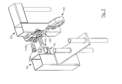
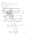
- FIGs 4 and 5 illustrate the assembled hinge assembly in accordance with the present invention.
- no access is available to either the grub screw 180 or the flanged nuts 200a, 200b.
- access to the hinge assembly is effectively prohibited as no deformation of the flange portions 140a', 140a", 140b', 140b" of the cover 140 is possible to provide access to the flanged nuts.
- bracket 30 forming part of the support or post 10 and the rail member 40 forming part of the gate 20, it will be appreciated that the bracket 30 may form part of the gate 20 and the rail member 40 may form part of the support or post 10.
- the mounting of the eye bolt 110 and the mounting plate 120 can be arranged for both right-hand openings and left-hand openings. In the latter case, the mounting plate 120 can be rotated through 180° with respect to the orientation shown in Figures 3 to 5 to provide the other handedness for the opening of the gate 20.
- the present invention is not limited to use on gates and may be used on any opening, for example, a door, where added security is required.
- the mounting pin 160 is given by way of example, and any other suitable type of mounting pin may also be used provided it provides the tamper-proof feature of not being able to be removed when in the closed and locked position.
- the mounting plate 120 is shown having two holes for fixing screws 150a, 150b, it will be appreciated that any suitable number of holes may be provided together with a suitable number of fixing screws.
- the sliding element located between the rail element and the gate may have a corresponding number of tapped holes for receiving the appropriate number of fixing screws.
- the gate is relatively light
- the ends of the top portion of the cover will need to be modified so that they can lie on top of one another whilst maintaining the angles between the portions 140a', 140b' and 140a", 140b" as described above and be secured with a single fixing screw.
- the sliding element in this case may have a single tapped hole for receiving the single fixing screw.
- the mounting plate is fixed by means of two or more fixing screws to the rail, such a cover could be fixed by means of only one of these fixing screws to the mounting plate.
Landscapes
- Engineering & Computer Science (AREA)
- Mechanical Engineering (AREA)
- Hinges (AREA)
- Gates (AREA)
- Clamps And Clips (AREA)
- Connection Of Plates (AREA)
Priority Applications (2)
| Application Number | Priority Date | Filing Date | Title |
|---|---|---|---|
| EP13158652.1A EP2778331A1 (de) | 2013-03-11 | 2013-03-11 | Scharnieranordnung |
| RU2014108768A RU2633234C2 (ru) | 2013-03-11 | 2014-03-06 | Петельный узел |
Applications Claiming Priority (1)
| Application Number | Priority Date | Filing Date | Title |
|---|---|---|---|
| EP13158652.1A EP2778331A1 (de) | 2013-03-11 | 2013-03-11 | Scharnieranordnung |
Publications (1)
| Publication Number | Publication Date |
|---|---|
| EP2778331A1 true EP2778331A1 (de) | 2014-09-17 |
Family
ID=47844203
Family Applications (1)
| Application Number | Title | Priority Date | Filing Date |
|---|---|---|---|
| EP13158652.1A Withdrawn EP2778331A1 (de) | 2013-03-11 | 2013-03-11 | Scharnieranordnung |
Country Status (2)
| Country | Link |
|---|---|
| EP (1) | EP2778331A1 (de) |
| RU (1) | RU2633234C2 (de) |
Cited By (15)
| Publication number | Priority date | Publication date | Assignee | Title |
|---|---|---|---|---|
| DE202015100193U1 (de) | 2015-01-16 | 2015-02-06 | Nikolaus Berlemann | Vorrichtung zur Sicherung einer Torbandanordnung und Toranlage mit einer solchen Vorrichtung |
| GB2559624A (en) * | 2017-02-14 | 2018-08-15 | Bja Trading Ltd | Hinge assemblies, method of installing same and gateways comprising same |
| WO2019048359A1 (en) | 2017-09-05 | 2019-03-14 | Locinox | DOOR CLOSURE DEVICE THAT CAN BE ADAPTED ON A DOOR WITH AN EYE BOLT HINGE |
| RU2772699C2 (ru) * | 2017-09-05 | 2022-05-24 | Локинокс | Закрывающий механизм для ворот, выполненный с возможностью установки на ворота с петлей с рым-болтом |
| CN117072005A (zh) * | 2022-05-09 | 2023-11-17 | 布勒(无锡)商业有限公司 | 铰链装置及设备组件 |
| EP4400684A1 (de) | 2023-01-13 | 2024-07-17 | Locinox | Torschliesser und verschlusssystem damit |
| WO2025073950A1 (en) | 2023-10-05 | 2025-04-10 | Locinox | A gate actuator |
| BE1032033A1 (nl) | 2023-10-05 | 2025-05-05 | Locinox Nv | Een poortactuator |
| BE1032034A1 (nl) | 2023-10-05 | 2025-05-05 | Locinox Nv | Een poortactuator |
| BE1032036A1 (nl) | 2023-10-05 | 2025-05-05 | Locinox Nv | Een poortactuator |
| BE1032121A1 (nl) | 2023-11-08 | 2025-06-03 | Locinox Nv | Een poortactuator |
| EP4610455A1 (de) | 2024-03-01 | 2025-09-03 | Locinox | Torpfosten |
| EP4610454A1 (de) | 2024-03-01 | 2025-09-03 | Locinox | Torpfosten |
| EP4610468A1 (de) | 2024-03-01 | 2025-09-03 | Locinox | Torpfosten |
| EP4671486A1 (de) | 2024-06-25 | 2025-12-31 | Locinox | Torpfosten |
Citations (3)
| Publication number | Priority date | Publication date | Assignee | Title |
|---|---|---|---|---|
| FR2565619A1 (fr) * | 1984-06-08 | 1985-12-13 | Barbier Claude | Penture reglable |
| DE4321894A1 (de) * | 1993-07-01 | 1995-01-12 | Heine & Sohn Anuba Beschlaege | Scharnierband |
| EP1528202A2 (de) | 2003-10-31 | 2005-05-04 | Joseph Talpe | Einrichtung für eine höheneinstellbare Halterung eines Tores |
Family Cites Families (2)
| Publication number | Priority date | Publication date | Assignee | Title |
|---|---|---|---|---|
| DE3630234C2 (de) * | 1986-09-05 | 1994-04-28 | Simonswerk Gmbh | Vorrichtung zur Befestigung eines Tür- oder Fensterbandes |
| DE19730145C2 (de) * | 1997-07-14 | 1999-07-01 | Sfs Ind Holding Ag | Bandteil zur Anordnung an Holz- oder Metallzargen für Fenster oder Türen |
-
2013
- 2013-03-11 EP EP13158652.1A patent/EP2778331A1/de not_active Withdrawn
-
2014
- 2014-03-06 RU RU2014108768A patent/RU2633234C2/ru active
Patent Citations (3)
| Publication number | Priority date | Publication date | Assignee | Title |
|---|---|---|---|---|
| FR2565619A1 (fr) * | 1984-06-08 | 1985-12-13 | Barbier Claude | Penture reglable |
| DE4321894A1 (de) * | 1993-07-01 | 1995-01-12 | Heine & Sohn Anuba Beschlaege | Scharnierband |
| EP1528202A2 (de) | 2003-10-31 | 2005-05-04 | Joseph Talpe | Einrichtung für eine höheneinstellbare Halterung eines Tores |
Cited By (20)
| Publication number | Priority date | Publication date | Assignee | Title |
|---|---|---|---|---|
| DE202015100193U1 (de) | 2015-01-16 | 2015-02-06 | Nikolaus Berlemann | Vorrichtung zur Sicherung einer Torbandanordnung und Toranlage mit einer solchen Vorrichtung |
| GB2559624A (en) * | 2017-02-14 | 2018-08-15 | Bja Trading Ltd | Hinge assemblies, method of installing same and gateways comprising same |
| GB2559624B (en) * | 2017-02-14 | 2020-12-02 | Bja Trading Ltd | Hinge assemblies, method of installing same and gateways comprising same |
| WO2019048359A1 (en) | 2017-09-05 | 2019-03-14 | Locinox | DOOR CLOSURE DEVICE THAT CAN BE ADAPTED ON A DOOR WITH AN EYE BOLT HINGE |
| RU2772699C2 (ru) * | 2017-09-05 | 2022-05-24 | Локинокс | Закрывающий механизм для ворот, выполненный с возможностью установки на ворота с петлей с рым-болтом |
| CN117072005A (zh) * | 2022-05-09 | 2023-11-17 | 布勒(无锡)商业有限公司 | 铰链装置及设备组件 |
| EP4400684A1 (de) | 2023-01-13 | 2024-07-17 | Locinox | Torschliesser und verschlusssystem damit |
| WO2025073952A1 (en) | 2023-10-05 | 2025-04-10 | Locinox | A gate actuator |
| WO2025073947A1 (en) | 2023-10-05 | 2025-04-10 | Locinox | A gate actuator |
| WO2025073946A1 (en) | 2023-10-05 | 2025-04-10 | Locinox | A gate actuator |
| WO2025073950A1 (en) | 2023-10-05 | 2025-04-10 | Locinox | A gate actuator |
| BE1032033A1 (nl) | 2023-10-05 | 2025-05-05 | Locinox Nv | Een poortactuator |
| BE1032034A1 (nl) | 2023-10-05 | 2025-05-05 | Locinox Nv | Een poortactuator |
| BE1032036A1 (nl) | 2023-10-05 | 2025-05-05 | Locinox Nv | Een poortactuator |
| BE1032121A1 (nl) | 2023-11-08 | 2025-06-03 | Locinox Nv | Een poortactuator |
| EP4610455A1 (de) | 2024-03-01 | 2025-09-03 | Locinox | Torpfosten |
| EP4610454A1 (de) | 2024-03-01 | 2025-09-03 | Locinox | Torpfosten |
| EP4610453A1 (de) | 2024-03-01 | 2025-09-03 | Locinox | Torpfosten |
| EP4610468A1 (de) | 2024-03-01 | 2025-09-03 | Locinox | Torpfosten |
| EP4671486A1 (de) | 2024-06-25 | 2025-12-31 | Locinox | Torpfosten |
Also Published As
| Publication number | Publication date |
|---|---|
| RU2633234C2 (ru) | 2017-10-11 |
| RU2014108768A (ru) | 2015-09-20 |
Similar Documents
| Publication | Publication Date | Title |
|---|---|---|
| EP2778331A1 (de) | Scharnieranordnung | |
| US7757349B2 (en) | Rack mounted component door system and method | |
| EP2645499B1 (de) | Türscharnier und Schaltschrank mit einem solchen Scharnier | |
| EP2589416B1 (de) | Brandschutzsprinklerträgersystem | |
| US8025166B2 (en) | Tool-less rack rail system incorporating clamping mechanism | |
| EP1183917B1 (de) | Befestigungsbügel für einen baugruppenträger und gerät und verfahren zur montage einer baugruppe in einem baugruppenträger | |
| US20150107052A1 (en) | Hinge assembly | |
| CN104047514A (zh) | 用于浴室门轨道组合件的可移除顶盖 | |
| BR112016017303B1 (pt) | Perfil de quadro de uma estrutura de quadro para um armário de comando elétrico ou distribuição e placa de montagem para uso com pelo menos o perfil de quadro | |
| BRPI1013689B1 (pt) | Sistema de prevenção de liberação para armário de parede | |
| EP3383152A1 (de) | Halterung für gleitschiene | |
| US9027988B2 (en) | Striker device for a motor vehicle door lock and a motor vehicle equipped with such striker device | |
| CN108729817A (zh) | 柜组件 | |
| EP2751606B1 (de) | Apparat und verfahren zur werkzeuglosen, lösbaren befestigung von komponenten an einem glasfaserverteilerschrank | |
| US7338241B2 (en) | Fastener receptacle | |
| KR200451230Y1 (ko) | 설치가 용이한 볼형 돔 감시카메라 | |
| KR100419526B1 (ko) | 간이착탈형 2축경첩구조 | |
| US8448325B2 (en) | Drawer dishwasher installation kit assembly | |
| KR101946151B1 (ko) | 프로파일용 도어 고정구 | |
| US8756764B2 (en) | Removable side hinge with temporary holding feature for a home appliance | |
| AU2004212546B2 (en) | Friction bar assembly | |
| CA2880222A1 (en) | Fire protection sprinkler support system | |
| JPS61156797A (ja) | 電子機器筐体 | |
| JP2023176151A5 (de) | ||
| US20070069523A1 (en) | Cabinet lock installation aid |
Legal Events
| Date | Code | Title | Description |
|---|---|---|---|
| PUAI | Public reference made under article 153(3) epc to a published international application that has entered the european phase |
Free format text: ORIGINAL CODE: 0009012 |
|
| 17P | Request for examination filed |
Effective date: 20130311 |
|
| AK | Designated contracting states |
Kind code of ref document: A1 Designated state(s): AL AT BE BG CH CY CZ DE DK EE ES FI FR GB GR HR HU IE IS IT LI LT LU LV MC MK MT NL NO PL PT RO RS SE SI SK SM TR |
|
| AX | Request for extension of the european patent |
Extension state: BA ME |
|
| R17P | Request for examination filed (corrected) |
Effective date: 20150317 |
|
| RBV | Designated contracting states (corrected) |
Designated state(s): AL AT BE BG CH CY CZ DE DK EE ES FI FR GB GR HR HU IE IS IT LI LT LU LV MC MK MT NL NO PL PT RO RS SE SI SK SM TR |
|
| GRAP | Despatch of communication of intention to grant a patent |
Free format text: ORIGINAL CODE: EPIDOSNIGR1 |
|
| RIC1 | Information provided on ipc code assigned before grant |
Ipc: E05D 7/04 20060101ALI20161025BHEP Ipc: E05D 5/02 20060101ALN20161025BHEP Ipc: E05D 11/00 20060101AFI20161025BHEP |
|
| INTG | Intention to grant announced |
Effective date: 20161117 |
|
| STAA | Information on the status of an ep patent application or granted ep patent |
Free format text: STATUS: THE APPLICATION IS DEEMED TO BE WITHDRAWN |
|
| 18D | Application deemed to be withdrawn |
Effective date: 20170328 |