EP2789736A1 - Système de drainage d'un rail - Google Patents
Système de drainage d'un rail Download PDFInfo
- Publication number
- EP2789736A1 EP2789736A1 EP20140163864 EP14163864A EP2789736A1 EP 2789736 A1 EP2789736 A1 EP 2789736A1 EP 20140163864 EP20140163864 EP 20140163864 EP 14163864 A EP14163864 A EP 14163864A EP 2789736 A1 EP2789736 A1 EP 2789736A1
- Authority
- EP
- European Patent Office
- Prior art keywords
- drainage
- rail
- connecting element
- channels
- drainage channels
- Prior art date
- Legal status (The legal status is an assumption and is not a legal conclusion. Google has not performed a legal analysis and makes no representation as to the accuracy of the status listed.)
- Granted
Links
- 238000009413 insulation Methods 0.000 claims description 12
- 238000000034 method Methods 0.000 claims description 8
- 239000012777 electrically insulating material Substances 0.000 claims 1
- 238000007789 sealing Methods 0.000 description 17
- XLYOFNOQVPJJNP-UHFFFAOYSA-N water Substances O XLYOFNOQVPJJNP-UHFFFAOYSA-N 0.000 description 16
- 239000004567 concrete Substances 0.000 description 13
- 238000009434 installation Methods 0.000 description 13
- 239000000565 sealant Substances 0.000 description 9
- 150000001875 compounds Chemical class 0.000 description 7
- 238000009415 formwork Methods 0.000 description 7
- 239000007788 liquid Substances 0.000 description 7
- 238000004519 manufacturing process Methods 0.000 description 7
- 230000035515 penetration Effects 0.000 description 6
- 239000000463 material Substances 0.000 description 5
- 230000003014 reinforcing effect Effects 0.000 description 3
- 229910000639 Spring steel Inorganic materials 0.000 description 1
- 229910000831 Steel Inorganic materials 0.000 description 1
- 230000003321 amplification Effects 0.000 description 1
- 238000004873 anchoring Methods 0.000 description 1
- 239000003795 chemical substances by application Substances 0.000 description 1
- 230000006835 compression Effects 0.000 description 1
- 238000007906 compression Methods 0.000 description 1
- 238000013016 damping Methods 0.000 description 1
- 239000012772 electrical insulation material Substances 0.000 description 1
- 230000009760 functional impairment Effects 0.000 description 1
- 238000001746 injection moulding Methods 0.000 description 1
- 239000012774 insulation material Substances 0.000 description 1
- 238000002955 isolation Methods 0.000 description 1
- 238000003199 nucleic acid amplification method Methods 0.000 description 1
- 239000011150 reinforced concrete Substances 0.000 description 1
- 239000004576 sand Substances 0.000 description 1
- 239000010959 steel Substances 0.000 description 1
- 230000007704 transition Effects 0.000 description 1
- 238000011179 visual inspection Methods 0.000 description 1
Images






Classifications
-
- E—FIXED CONSTRUCTIONS
- E01—CONSTRUCTION OF ROADS, RAILWAYS, OR BRIDGES
- E01B—PERMANENT WAY; PERMANENT-WAY TOOLS; MACHINES FOR MAKING RAILWAYS OF ALL KINDS
- E01B1/00—Ballastway; Other means for supporting the sleepers or the track; Drainage of the ballastway
- E01B1/008—Drainage of track
-
- E—FIXED CONSTRUCTIONS
- E01—CONSTRUCTION OF ROADS, RAILWAYS, OR BRIDGES
- E01B—PERMANENT WAY; PERMANENT-WAY TOOLS; MACHINES FOR MAKING RAILWAYS OF ALL KINDS
- E01B21/00—Track superstructure adapted for tramways in paved streets
- E01B21/02—Special supporting means; Draining of rails
Definitions
- the present invention relates to a drainage system for a rail and a method for assembling such a drainage system.
- the connecting element is biased in the radial direction.
- a particularly easy to produce connecting element is provided.
- An assembly is thereby advantageously simplified because the connecting element only needs to be compressed, in particular radially inwards, and then (after installation) automatically adapts to the cross section of the drainage channel due to its bias.
- a tight connection between connecting element and drainage channel is also made possible in a particularly advantageous manner.
- the connecting element is positively and / or non-positively connected to the insides of the drainage channels.
- the connecting element is connected after installation cohesively with the drainage channels, in particular glued or welded.
- the tightness of the drainage system is improved in an advantageous manner.
- the connecting element and / or the drainage channels to a sealing element, in particular a sealing lip which connects the connecting element and drainage channel liquid-tight.
- the connecting element has projections which interact resiliently with the rail.
- the projections act positively and / or non-positively with the underside of the rail together.
- the underside of the rail it is also meant an optionally arranged other element there. As a result, a particularly accurate positioning of the connecting element is made possible.
- the system comprises an insulation means, which is formed in particular from an electrical insulation material.
- the insulating means is formed of a thermal and / or acoustic insulation material.
- the closure flaps on their side facing the drainage channel on a seal, in particular a sealing lip, which is preferably formed circumferentially and sealingly cooperates with the drainage channel.
- the connecting element also has at one end or at both ends a further closing flap and / or a spring element.
- a dirt entry is prevented in an advantageous manner and / or a formwork element provided.
- the spring element presses the closure cap, for example, against the rail and thereby improves the form and / or frictional engagement between the two elements.
- the further closure flap has an at least partially encircling seal, in particular a sealing lip.
- a sealing of the drainage system in the region of the transition between the connecting element and drainage channel and / or rail against dirt entry and / or penetration of concrete and / or sealant is made possible in an advantageous manner.
- the object is achieved by a method for mounting a drainage system for a rail, wherein in a first step on both sides of the rail and preferably transverse to the rail two drainage channels are arranged, wherein in a second step, the cross section of an elastically deformable connecting element by applying force is reduced and the connecting element is arranged below the rail and transversely to the rail and at least partially overlapping with the drainage channels on the inside of the drainage channels, wherein in a third step, the force is released, so that the connecting element to the shape of the inner cross section of Dewatering channel adapts.
- the drainage system is then at least partially embedded in concrete and / or surrounded by a sealant.
- the connecting element is introduced into the drainage channel with the side at which the distance between end region and stop element is greater.
- the drainage system is then at least partially embedded in concrete and / or surrounded by a sealant.
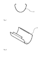
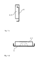
- FIG. 1 an inventive connecting element 3 according to an exemplary first embodiment is shown in a schematic sectional view.
- the connecting element 3 is made for example of spring steel or plastic and has a substantially circular arc-shaped cross-section. It is elastically deformable. In the illustrated first embodiment, the connecting element 3 is biased outwardly. At the upper edges, the connecting element 3 has resiliently formed projections.
- connection element 3 according to the invention according to the exemplary first embodiment is shown in a schematic perspective view. It can be seen that the connecting element 3 essentially has the shape of a half hollow cylinder, that is to say a channel shape.
- the resilient projections are formed integrally with the connecting element 3, but do not extend over the entire length of the connecting element 3. Alternatively, a plurality of individual resilient projections are conceivable.
- FIG. 3 is a drainage system according to the invention with a connecting element 3 according to the exemplary first embodiment shown in a schematic side sectional view.
- the connecting element 3 corresponds to the in the Figures 1 and 2 Transverse to the main extension direction of a rail 1, which here runs perpendicular to the plane, two drainage channels 2 are arranged, one drainage channel 2 to both sides of the rail 1.
- an insulating means 5 is arranged positively or cohesively, the the drainage system, ie essentially the connecting element 3 and the drainage channels 2 of the rail 1 electrically isolated.
- the insulating means 5 is used for mechanical, acoustic or thermal insulation, or any combination thereof.
- FIG. 5 an inventive drainage system with a connecting element 3 according to the exemplary first embodiment is shown in a schematic plan view.
- the section line CC corresponds to the selected section line in FIG. 3 .
- the drainage opening 8 extends over the entire width of the connecting element 3.
- a smaller extension is conceivable.
- the two-sided overlap of the connecting element 3 with the drainage channels 2 can be clearly seen.
- FIG. 6 an inventive drainage system with a connecting element 3 according to an exemplary second embodiment is shown in a schematic sectional view.
- the connecting element 3 is rigid and has two stop elements 4, 4 ', which are arranged on the outer side of the end portions of the connecting element 3 and that at different distances from the respective end region. In particular, one distance is twice the other distance.
- the second embodiment essentially corresponds to the first embodiment, wherein, in the embodiment shown here, further no insulation means 5 is arranged around the rail.
- a second drainage channel 2 is arranged correspondingly symmetrically to the first drainage channel 2 on the other side of the rail.
- the connecting element 3 is then moved opposite to the first direction of movement, in this case from left to right, until the second stop element 4 'abuts the second drainage channel 2.
- the rail 1 is located directly on the connecting element 3.
- a flat layer of an insulating means 5 is arranged between rail 1 and connecting element 3.
- a concreting and / or sealing is provided subsequent to the assembly.
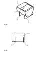
- FIGS. 9a to 9d a connection element 3 according to the invention according to an exemplary third embodiment is shown in various schematic views.
- FIG. 9a is a schematic perspective view of the connecting element 3 according to the third embodiment shown.
- the third embodiment corresponds essentially to the second embodiment, with the difference that the connecting element 3 upwards, ie in the direction of the rail 1, partially closed.
- the position of the opening is matched to the position of the drainage opening 8 in the rail and optionally the insulation means 5.
- the opening is larger than the drainage opening 8, to allow easy positioning.
- the cover is positive, non-positive or cohesive with the Connecting element 3 connected.
- the cover is formed integrally with the connecting element 3.
- FIGS. 9b to 9d correspond to different views of the connecting element 3 according to the third embodiment.
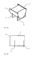
- connection element 3 according to the invention according to an exemplary fourth embodiment is shown in various schematic views.
- the fourth embodiment corresponds essentially to the third embodiment, but here two openings on the outer sides, ie in the end regions of the connecting element 3 are arranged.
- the rail has lateral drainage openings 8, so that the water is conducted into the connecting element 3 in the end regions.
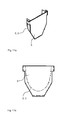
- the surface of the closure flap 6 substantially corresponds to the cross section of the drainage channel 2.
- Such a closure flap 6 can also be attached to one or both sides of the connecting element 3.
- the closure flap 6 is alternatively materially connected to the drainage channel 2, for example glued or welded to this.
- FIGS. 12a to 12d a further closure flap 6 'according to the invention is shown in various schematic views according to an exemplary embodiment.
- the further closure flap 6 ' substantially corresponds to the closure flap 6, with the difference that the further closure flap 6' extends only in an upper area of the drainage channel 2 or the connecting element 3.
- the further closure flap 6 ' is arranged on an end region facing the rail 1 and has a resilient projection which is positively and / or non-positively connected to the rail 1 or a possible insulating means 5 is applied and thus seals the drainage system, in particular against liquid and foreign bodies.
- the further closure flap 6 ' serves as a formwork element for a concreting or sealing.
- the further closure flap 6 ' can also be fixedly arranged on the drainage channel 2 or the connecting element 3, for example it can be riveted or welded or glued thereto.
Landscapes
- Engineering & Computer Science (AREA)
- Architecture (AREA)
- Civil Engineering (AREA)
- Structural Engineering (AREA)
- Railway Tracks (AREA)
- Sink And Installation For Waste Water (AREA)
Applications Claiming Priority (1)
| Application Number | Priority Date | Filing Date | Title |
|---|---|---|---|
| DE201310206602 DE102013206602A1 (de) | 2013-04-12 | 2013-04-12 | Entwässerungssystem für eine Schiene |
Publications (2)
| Publication Number | Publication Date |
|---|---|
| EP2789736A1 true EP2789736A1 (fr) | 2014-10-15 |
| EP2789736B1 EP2789736B1 (fr) | 2019-06-26 |
Family
ID=50478236
Family Applications (1)
| Application Number | Title | Priority Date | Filing Date |
|---|---|---|---|
| EP14163864.3A Active EP2789736B1 (fr) | 2013-04-12 | 2014-04-08 | Système de drainage d'un rail |
Country Status (2)
| Country | Link |
|---|---|
| EP (1) | EP2789736B1 (fr) |
| DE (1) | DE102013206602A1 (fr) |
Citations (4)
| Publication number | Priority date | Publication date | Assignee | Title |
|---|---|---|---|---|
| DE20005074U1 (de) * | 2000-03-20 | 2000-06-29 | Hauraton Betonwarenfabrik GmbH & Co KG, 76437 Rastatt | Schienenentwässerungssystem |
| DE102007024606A1 (de) * | 2006-06-03 | 2007-12-13 | Hauraton Gmbh & Co. Kg | Entwässerungsvorrichtung |
| EP2418322A2 (fr) * | 2010-08-10 | 2012-02-15 | HAURATON GmbH & Co. KG | Caniveau de drainage |
| WO2013017752A1 (fr) * | 2011-08-04 | 2013-02-07 | Aco Produits Polymeres | Caniveau pour voie ferrée de tramway |
Family Cites Families (1)
| Publication number | Priority date | Publication date | Assignee | Title |
|---|---|---|---|---|
| DE4340787A1 (de) * | 1993-11-23 | 1995-05-24 | Frenzel Otto Bauunternehmen | Vorrichtung zum Auffangen von Schadstoffen im Schienenbereich |
-
2013
- 2013-04-12 DE DE201310206602 patent/DE102013206602A1/de not_active Withdrawn
-
2014
- 2014-04-08 EP EP14163864.3A patent/EP2789736B1/fr active Active
Patent Citations (4)
| Publication number | Priority date | Publication date | Assignee | Title |
|---|---|---|---|---|
| DE20005074U1 (de) * | 2000-03-20 | 2000-06-29 | Hauraton Betonwarenfabrik GmbH & Co KG, 76437 Rastatt | Schienenentwässerungssystem |
| DE102007024606A1 (de) * | 2006-06-03 | 2007-12-13 | Hauraton Gmbh & Co. Kg | Entwässerungsvorrichtung |
| EP2418322A2 (fr) * | 2010-08-10 | 2012-02-15 | HAURATON GmbH & Co. KG | Caniveau de drainage |
| WO2013017752A1 (fr) * | 2011-08-04 | 2013-02-07 | Aco Produits Polymeres | Caniveau pour voie ferrée de tramway |
Also Published As
| Publication number | Publication date |
|---|---|
| DE102013206602A1 (de) | 2014-10-30 |
| EP2789736B1 (fr) | 2019-06-26 |
Similar Documents
| Publication | Publication Date | Title |
|---|---|---|
| DE102018211473B3 (de) | Batteriegehäuse | |
| EP2418322B1 (fr) | Caniveau de drainage | |
| WO2015040118A1 (fr) | Cale électriquement isolante destinée à la fixation d'un rail | |
| DE202016101390U1 (de) | Mitteldichtungsblock und Mitteldichtungsblocksystem für eine Hebeschiebtür | |
| WO2010083935A1 (fr) | Sabot pour traverses | |
| EP2789736B1 (fr) | Système de drainage d'un rail | |
| DE102009007442A1 (de) | Brücke oder Brückenabschnitt | |
| DE102007024606A1 (de) | Entwässerungsvorrichtung | |
| WO2021047960A1 (fr) | Dispositif de drainage | |
| DE4320284C2 (de) | Dichtungsanordnung für den Einsatz bei mechanisch miteinander zu verbindenden Pfosten- und Rahmenelementen | |
| DE102016112720A1 (de) | Dämpfungsanordnung für Gleise | |
| EP3597834B1 (fr) | Composant pour un dispositif d'écoulement pour un toit plat doté d'un comble | |
| EP2108739B1 (fr) | Système de construction routière pour étanchéifier des joints | |
| EP1719848A2 (fr) | Caniveau d'écoulement composé d'éléments de caniveau | |
| EP2194190B1 (fr) | Dispositif pontant pour un joint de dilatation | |
| DE102007051189A1 (de) | Ablaufeinrichtung | |
| DE202015104176U1 (de) | Zusatzvorrichtung zur Verringerung der Barrierewirkung einer Schwelle | |
| DE102005003962A1 (de) | Schienensystem mit zugeordnetem Schienenanbaukasten | |
| EP2762659B1 (fr) | Dispositif de montage et de réparation | |
| DE202013101195U1 (de) | Fahrbahnübergang | |
| EP1651822A1 (fr) | Dispositif d'ecoulement des eaux de ruissellement | |
| EP3763880B1 (fr) | Dispositif, de préférence d'encastrement affleurant la surface de la chaussée | |
| DE102013103654A1 (de) | Verbindungseinrichtung zum im Wesentlichen dichten Verbinden eines ersten Kanalelements mit einem zweiten Kanalelement eines Kanals | |
| DE102017116116A1 (de) | Anordnung für ein Fahrzeugdach, Fahrzeugdach für ein Kraftfahrzeug und Verfahren zum Herstellen einer Anordnung für ein Fahrzeugdach | |
| EP1930512A2 (fr) | Dispositif de montage dans une conduite |
Legal Events
| Date | Code | Title | Description |
|---|---|---|---|
| PUAI | Public reference made under article 153(3) epc to a published international application that has entered the european phase |
Free format text: ORIGINAL CODE: 0009012 |
|
| 17P | Request for examination filed |
Effective date: 20140408 |
|
| AK | Designated contracting states |
Kind code of ref document: A1 Designated state(s): AL AT BE BG CH CY CZ DE DK EE ES FI FR GB GR HR HU IE IS IT LI LT LU LV MC MK MT NL NO PL PT RO RS SE SI SK SM TR |
|
| AX | Request for extension of the european patent |
Extension state: BA ME |
|
| R17P | Request for examination filed (corrected) |
Effective date: 20150415 |
|
| RBV | Designated contracting states (corrected) |
Designated state(s): AL AT BE BG CH CY CZ DE DK EE ES FI FR GB GR HR HU IE IS IT LI LT LU LV MC MK MT NL NO PL PT RO RS SE SI SK SM TR |
|
| STAA | Information on the status of an ep patent application or granted ep patent |
Free format text: STATUS: EXAMINATION IS IN PROGRESS |
|
| 17Q | First examination report despatched |
Effective date: 20170811 |
|
| GRAP | Despatch of communication of intention to grant a patent |
Free format text: ORIGINAL CODE: EPIDOSNIGR1 |
|
| STAA | Information on the status of an ep patent application or granted ep patent |
Free format text: STATUS: GRANT OF PATENT IS INTENDED |
|
| INTG | Intention to grant announced |
Effective date: 20190213 |
|
| GRAS | Grant fee paid |
Free format text: ORIGINAL CODE: EPIDOSNIGR3 |
|
| GRAA | (expected) grant |
Free format text: ORIGINAL CODE: 0009210 |
|
| STAA | Information on the status of an ep patent application or granted ep patent |
Free format text: STATUS: THE PATENT HAS BEEN GRANTED |
|
| AK | Designated contracting states |
Kind code of ref document: B1 Designated state(s): AL AT BE BG CH CY CZ DE DK EE ES FI FR GB GR HR HU IE IS IT LI LT LU LV MC MK MT NL NO PL PT RO RS SE SI SK SM TR |
|
| REG | Reference to a national code |
Ref country code: GB Ref legal event code: FG4D Free format text: NOT ENGLISH |
|
| REG | Reference to a national code |
Ref country code: CH Ref legal event code: EP |
|
| REG | Reference to a national code |
Ref country code: AT Ref legal event code: REF Ref document number: 1148419 Country of ref document: AT Kind code of ref document: T Effective date: 20190715 |
|
| REG | Reference to a national code |
Ref country code: DE Ref legal event code: R096 Ref document number: 502014012047 Country of ref document: DE |
|
| REG | Reference to a national code |
Ref country code: IE Ref legal event code: FG4D Free format text: LANGUAGE OF EP DOCUMENT: GERMAN |
|
| REG | Reference to a national code |
Ref country code: NL Ref legal event code: MP Effective date: 20190626 |
|
| PG25 | Lapsed in a contracting state [announced via postgrant information from national office to epo] |
Ref country code: NO Free format text: LAPSE BECAUSE OF FAILURE TO SUBMIT A TRANSLATION OF THE DESCRIPTION OR TO PAY THE FEE WITHIN THE PRESCRIBED TIME-LIMIT Effective date: 20190926 Ref country code: AL Free format text: LAPSE BECAUSE OF FAILURE TO SUBMIT A TRANSLATION OF THE DESCRIPTION OR TO PAY THE FEE WITHIN THE PRESCRIBED TIME-LIMIT Effective date: 20190626 Ref country code: FI Free format text: LAPSE BECAUSE OF FAILURE TO SUBMIT A TRANSLATION OF THE DESCRIPTION OR TO PAY THE FEE WITHIN THE PRESCRIBED TIME-LIMIT Effective date: 20190626 Ref country code: HR Free format text: LAPSE BECAUSE OF FAILURE TO SUBMIT A TRANSLATION OF THE DESCRIPTION OR TO PAY THE FEE WITHIN THE PRESCRIBED TIME-LIMIT Effective date: 20190626 Ref country code: SE Free format text: LAPSE BECAUSE OF FAILURE TO SUBMIT A TRANSLATION OF THE DESCRIPTION OR TO PAY THE FEE WITHIN THE PRESCRIBED TIME-LIMIT Effective date: 20190626 Ref country code: LT Free format text: LAPSE BECAUSE OF FAILURE TO SUBMIT A TRANSLATION OF THE DESCRIPTION OR TO PAY THE FEE WITHIN THE PRESCRIBED TIME-LIMIT Effective date: 20190626 |
|
| REG | Reference to a national code |
Ref country code: LT Ref legal event code: MG4D |
|
| PG25 | Lapsed in a contracting state [announced via postgrant information from national office to epo] |
Ref country code: GR Free format text: LAPSE BECAUSE OF FAILURE TO SUBMIT A TRANSLATION OF THE DESCRIPTION OR TO PAY THE FEE WITHIN THE PRESCRIBED TIME-LIMIT Effective date: 20190927 Ref country code: BG Free format text: LAPSE BECAUSE OF FAILURE TO SUBMIT A TRANSLATION OF THE DESCRIPTION OR TO PAY THE FEE WITHIN THE PRESCRIBED TIME-LIMIT Effective date: 20190926 Ref country code: RS Free format text: LAPSE BECAUSE OF FAILURE TO SUBMIT A TRANSLATION OF THE DESCRIPTION OR TO PAY THE FEE WITHIN THE PRESCRIBED TIME-LIMIT Effective date: 20190626 Ref country code: LV Free format text: LAPSE BECAUSE OF FAILURE TO SUBMIT A TRANSLATION OF THE DESCRIPTION OR TO PAY THE FEE WITHIN THE PRESCRIBED TIME-LIMIT Effective date: 20190626 |
|
| PG25 | Lapsed in a contracting state [announced via postgrant information from national office to epo] |
Ref country code: CZ Free format text: LAPSE BECAUSE OF FAILURE TO SUBMIT A TRANSLATION OF THE DESCRIPTION OR TO PAY THE FEE WITHIN THE PRESCRIBED TIME-LIMIT Effective date: 20190626 Ref country code: RO Free format text: LAPSE BECAUSE OF FAILURE TO SUBMIT A TRANSLATION OF THE DESCRIPTION OR TO PAY THE FEE WITHIN THE PRESCRIBED TIME-LIMIT Effective date: 20190626 Ref country code: EE Free format text: LAPSE BECAUSE OF FAILURE TO SUBMIT A TRANSLATION OF THE DESCRIPTION OR TO PAY THE FEE WITHIN THE PRESCRIBED TIME-LIMIT Effective date: 20190626 Ref country code: NL Free format text: LAPSE BECAUSE OF FAILURE TO SUBMIT A TRANSLATION OF THE DESCRIPTION OR TO PAY THE FEE WITHIN THE PRESCRIBED TIME-LIMIT Effective date: 20190626 Ref country code: SK Free format text: LAPSE BECAUSE OF FAILURE TO SUBMIT A TRANSLATION OF THE DESCRIPTION OR TO PAY THE FEE WITHIN THE PRESCRIBED TIME-LIMIT Effective date: 20190626 Ref country code: PT Free format text: LAPSE BECAUSE OF FAILURE TO SUBMIT A TRANSLATION OF THE DESCRIPTION OR TO PAY THE FEE WITHIN THE PRESCRIBED TIME-LIMIT Effective date: 20191028 |
|
| PG25 | Lapsed in a contracting state [announced via postgrant information from national office to epo] |
Ref country code: SM Free format text: LAPSE BECAUSE OF FAILURE TO SUBMIT A TRANSLATION OF THE DESCRIPTION OR TO PAY THE FEE WITHIN THE PRESCRIBED TIME-LIMIT Effective date: 20190626 Ref country code: IT Free format text: LAPSE BECAUSE OF FAILURE TO SUBMIT A TRANSLATION OF THE DESCRIPTION OR TO PAY THE FEE WITHIN THE PRESCRIBED TIME-LIMIT Effective date: 20190626 Ref country code: IS Free format text: LAPSE BECAUSE OF FAILURE TO SUBMIT A TRANSLATION OF THE DESCRIPTION OR TO PAY THE FEE WITHIN THE PRESCRIBED TIME-LIMIT Effective date: 20191026 Ref country code: ES Free format text: LAPSE BECAUSE OF FAILURE TO SUBMIT A TRANSLATION OF THE DESCRIPTION OR TO PAY THE FEE WITHIN THE PRESCRIBED TIME-LIMIT Effective date: 20190626 |
|
| PG25 | Lapsed in a contracting state [announced via postgrant information from national office to epo] |
Ref country code: TR Free format text: LAPSE BECAUSE OF FAILURE TO SUBMIT A TRANSLATION OF THE DESCRIPTION OR TO PAY THE FEE WITHIN THE PRESCRIBED TIME-LIMIT Effective date: 20190626 |
|
| PG25 | Lapsed in a contracting state [announced via postgrant information from national office to epo] |
Ref country code: DK Free format text: LAPSE BECAUSE OF FAILURE TO SUBMIT A TRANSLATION OF THE DESCRIPTION OR TO PAY THE FEE WITHIN THE PRESCRIBED TIME-LIMIT Effective date: 20190626 Ref country code: PL Free format text: LAPSE BECAUSE OF FAILURE TO SUBMIT A TRANSLATION OF THE DESCRIPTION OR TO PAY THE FEE WITHIN THE PRESCRIBED TIME-LIMIT Effective date: 20190626 |
|
| PG25 | Lapsed in a contracting state [announced via postgrant information from national office to epo] |
Ref country code: IS Free format text: LAPSE BECAUSE OF FAILURE TO SUBMIT A TRANSLATION OF THE DESCRIPTION OR TO PAY THE FEE WITHIN THE PRESCRIBED TIME-LIMIT Effective date: 20200224 |
|
| REG | Reference to a national code |
Ref country code: DE Ref legal event code: R097 Ref document number: 502014012047 Country of ref document: DE |
|
| PLBE | No opposition filed within time limit |
Free format text: ORIGINAL CODE: 0009261 |
|
| STAA | Information on the status of an ep patent application or granted ep patent |
Free format text: STATUS: NO OPPOSITION FILED WITHIN TIME LIMIT |
|
| PG2D | Information on lapse in contracting state deleted |
Ref country code: IS |
|
| 26N | No opposition filed |
Effective date: 20200603 |
|
| PG25 | Lapsed in a contracting state [announced via postgrant information from national office to epo] |
Ref country code: SI Free format text: LAPSE BECAUSE OF FAILURE TO SUBMIT A TRANSLATION OF THE DESCRIPTION OR TO PAY THE FEE WITHIN THE PRESCRIBED TIME-LIMIT Effective date: 20190626 |
|
| PG25 | Lapsed in a contracting state [announced via postgrant information from national office to epo] |
Ref country code: MC Free format text: LAPSE BECAUSE OF FAILURE TO SUBMIT A TRANSLATION OF THE DESCRIPTION OR TO PAY THE FEE WITHIN THE PRESCRIBED TIME-LIMIT Effective date: 20190626 |
|
| REG | Reference to a national code |
Ref country code: CH Ref legal event code: PL |
|
| PG25 | Lapsed in a contracting state [announced via postgrant information from national office to epo] |
Ref country code: CH Free format text: LAPSE BECAUSE OF NON-PAYMENT OF DUE FEES Effective date: 20200430 Ref country code: LU Free format text: LAPSE BECAUSE OF NON-PAYMENT OF DUE FEES Effective date: 20200408 Ref country code: LI Free format text: LAPSE BECAUSE OF NON-PAYMENT OF DUE FEES Effective date: 20200430 |
|
| REG | Reference to a national code |
Ref country code: BE Ref legal event code: MM Effective date: 20200430 |
|
| PG25 | Lapsed in a contracting state [announced via postgrant information from national office to epo] |
Ref country code: BE Free format text: LAPSE BECAUSE OF NON-PAYMENT OF DUE FEES Effective date: 20200430 |
|
| GBPC | Gb: european patent ceased through non-payment of renewal fee |
Effective date: 20200408 |
|
| PG25 | Lapsed in a contracting state [announced via postgrant information from national office to epo] |
Ref country code: IE Free format text: LAPSE BECAUSE OF NON-PAYMENT OF DUE FEES Effective date: 20200408 Ref country code: GB Free format text: LAPSE BECAUSE OF NON-PAYMENT OF DUE FEES Effective date: 20200408 |
|
| REG | Reference to a national code |
Ref country code: AT Ref legal event code: MM01 Ref document number: 1148419 Country of ref document: AT Kind code of ref document: T Effective date: 20200408 |
|
| PG25 | Lapsed in a contracting state [announced via postgrant information from national office to epo] |
Ref country code: AT Free format text: LAPSE BECAUSE OF NON-PAYMENT OF DUE FEES Effective date: 20200408 |
|
| PG25 | Lapsed in a contracting state [announced via postgrant information from national office to epo] |
Ref country code: MT Free format text: LAPSE BECAUSE OF FAILURE TO SUBMIT A TRANSLATION OF THE DESCRIPTION OR TO PAY THE FEE WITHIN THE PRESCRIBED TIME-LIMIT Effective date: 20190626 Ref country code: CY Free format text: LAPSE BECAUSE OF FAILURE TO SUBMIT A TRANSLATION OF THE DESCRIPTION OR TO PAY THE FEE WITHIN THE PRESCRIBED TIME-LIMIT Effective date: 20190626 |
|
| PG25 | Lapsed in a contracting state [announced via postgrant information from national office to epo] |
Ref country code: MK Free format text: LAPSE BECAUSE OF FAILURE TO SUBMIT A TRANSLATION OF THE DESCRIPTION OR TO PAY THE FEE WITHIN THE PRESCRIBED TIME-LIMIT Effective date: 20190626 |
|
| PGFP | Annual fee paid to national office [announced via postgrant information from national office to epo] |
Ref country code: FR Payment date: 20220420 Year of fee payment: 9 Ref country code: DE Payment date: 20220419 Year of fee payment: 9 |
|
| REG | Reference to a national code |
Ref country code: DE Ref legal event code: R119 Ref document number: 502014012047 Country of ref document: DE |
|
| PG25 | Lapsed in a contracting state [announced via postgrant information from national office to epo] |
Ref country code: FR Free format text: LAPSE BECAUSE OF NON-PAYMENT OF DUE FEES Effective date: 20230430 Ref country code: DE Free format text: LAPSE BECAUSE OF NON-PAYMENT OF DUE FEES Effective date: 20231103 |