EP2790318B1 - Elektronische steuerungsvorrichtung mit versorgungsspannungsüebrwachungsfunktion und fahrzeuglenkungssteuerungsvorrichtung damit - Google Patents
Elektronische steuerungsvorrichtung mit versorgungsspannungsüebrwachungsfunktion und fahrzeuglenkungssteuerungsvorrichtung damit Download PDFInfo
- Publication number
- EP2790318B1 EP2790318B1 EP11877153.4A EP11877153A EP2790318B1 EP 2790318 B1 EP2790318 B1 EP 2790318B1 EP 11877153 A EP11877153 A EP 11877153A EP 2790318 B1 EP2790318 B1 EP 2790318B1
- Authority
- EP
- European Patent Office
- Prior art keywords
- power
- electronic control
- supply voltage
- voltage
- supply
- Prior art date
- Legal status (The legal status is an assumption and is not a legal conclusion. Google has not performed a legal analysis and makes no representation as to the accuracy of the status listed.)
- Active
Links
Images




Classifications
-
- H—ELECTRICITY
- H02—GENERATION; CONVERSION OR DISTRIBUTION OF ELECTRIC POWER
- H02H—EMERGENCY PROTECTIVE CIRCUIT ARRANGEMENTS
- H02H7/00—Emergency protective circuit arrangements specially adapted for specific types of electric machines or apparatus or for sectionalised protection of cable or line systems, and effecting automatic switching in the event of an undesired change from normal working conditions
- H02H7/08—Emergency protective circuit arrangements specially adapted for specific types of electric machines or apparatus or for sectionalised protection of cable or line systems, and effecting automatic switching in the event of an undesired change from normal working conditions for dynamo-electric motors
-
- B—PERFORMING OPERATIONS; TRANSPORTING
- B62—LAND VEHICLES FOR TRAVELLING OTHERWISE THAN ON RAILS
- B62D—MOTOR VEHICLES; TRAILERS
- B62D6/00—Arrangements for automatically controlling steering depending on driving conditions sensed and responded to, e.g. control circuits
-
- B—PERFORMING OPERATIONS; TRANSPORTING
- B62—LAND VEHICLES FOR TRAVELLING OTHERWISE THAN ON RAILS
- B62D—MOTOR VEHICLES; TRAILERS
- B62D5/00—Power-assisted or power-driven steering
-
- B—PERFORMING OPERATIONS; TRANSPORTING
- B62—LAND VEHICLES FOR TRAVELLING OTHERWISE THAN ON RAILS
- B62D—MOTOR VEHICLES; TRAILERS
- B62D5/00—Power-assisted or power-driven steering
- B62D5/04—Power-assisted or power-driven steering electrical, e.g. using an electric servo-motor connected to, or forming part of, the steering gear
-
- B—PERFORMING OPERATIONS; TRANSPORTING
- B62—LAND VEHICLES FOR TRAVELLING OTHERWISE THAN ON RAILS
- B62D—MOTOR VEHICLES; TRAILERS
- B62D5/00—Power-assisted or power-driven steering
- B62D5/04—Power-assisted or power-driven steering electrical, e.g. using an electric servo-motor connected to, or forming part of, the steering gear
- B62D5/0457—Power-assisted or power-driven steering electrical, e.g. using an electric servo-motor connected to, or forming part of, the steering gear characterised by control features of the drive means as such
- B62D5/0481—Power-assisted or power-driven steering electrical, e.g. using an electric servo-motor connected to, or forming part of, the steering gear characterised by control features of the drive means as such monitoring the steering system, e.g. failures
-
- B—PERFORMING OPERATIONS; TRANSPORTING
- B62—LAND VEHICLES FOR TRAVELLING OTHERWISE THAN ON RAILS
- B62D—MOTOR VEHICLES; TRAILERS
- B62D5/00—Power-assisted or power-driven steering
- B62D5/04—Power-assisted or power-driven steering electrical, e.g. using an electric servo-motor connected to, or forming part of, the steering gear
- B62D5/0457—Power-assisted or power-driven steering electrical, e.g. using an electric servo-motor connected to, or forming part of, the steering gear characterised by control features of the drive means as such
- B62D5/0481—Power-assisted or power-driven steering electrical, e.g. using an electric servo-motor connected to, or forming part of, the steering gear characterised by control features of the drive means as such monitoring the steering system, e.g. failures
- B62D5/0484—Power-assisted or power-driven steering electrical, e.g. using an electric servo-motor connected to, or forming part of, the steering gear characterised by control features of the drive means as such monitoring the steering system, e.g. failures for reaction to failures, e.g. limp home
-
- G—PHYSICS
- G05—CONTROLLING; REGULATING
- G05F—SYSTEMS FOR REGULATING ELECTRIC OR MAGNETIC VARIABLES
- G05F1/00—Automatic systems in which deviations of an electric quantity from one or more predetermined values are detected at the output of the system and fed back to a device within the system to restore the detected quantity to its predetermined value or values, i.e. retroactive systems
- G05F1/10—Regulating voltage or current
- G05F1/46—Regulating voltage or current wherein the variable actually regulated by the final control device is DC
- G05F1/56—Regulating voltage or current wherein the variable actually regulated by the final control device is DC using semiconductor devices in series with the load as final control devices
- G05F1/565—Regulating voltage or current wherein the variable actually regulated by the final control device is DC using semiconductor devices in series with the load as final control devices sensing a condition of the system or its load in addition to means responsive to deviations in the output of the system, e.g. current, voltage, power factor
- G05F1/569—Regulating voltage or current wherein the variable actually regulated by the final control device is DC using semiconductor devices in series with the load as final control devices sensing a condition of the system or its load in addition to means responsive to deviations in the output of the system, e.g. current, voltage, power factor for protection
-
- H—ELECTRICITY
- H02—GENERATION; CONVERSION OR DISTRIBUTION OF ELECTRIC POWER
- H02H—EMERGENCY PROTECTIVE CIRCUIT ARRANGEMENTS
- H02H3/00—Emergency protective circuit arrangements for automatic disconnection directly responsive to an undesired change from normal electric working condition with or without subsequent reconnection ; integrated protection
- H02H3/20—Emergency protective circuit arrangements for automatic disconnection directly responsive to an undesired change from normal electric working condition with or without subsequent reconnection ; integrated protection responsive to excess voltage
-
- H—ELECTRICITY
- H02—GENERATION; CONVERSION OR DISTRIBUTION OF ELECTRIC POWER
- H02H—EMERGENCY PROTECTIVE CIRCUIT ARRANGEMENTS
- H02H7/00—Emergency protective circuit arrangements specially adapted for specific types of electric machines or apparatus or for sectionalised protection of cable or line systems, and effecting automatic switching in the event of an undesired change from normal working conditions
- H02H7/08—Emergency protective circuit arrangements specially adapted for specific types of electric machines or apparatus or for sectionalised protection of cable or line systems, and effecting automatic switching in the event of an undesired change from normal working conditions for dynamo-electric motors
- H02H7/09—Emergency protective circuit arrangements specially adapted for specific types of electric machines or apparatus or for sectionalised protection of cable or line systems, and effecting automatic switching in the event of an undesired change from normal working conditions for dynamo-electric motors against over-voltage; against reduction of voltage; against phase interruption
-
- H—ELECTRICITY
- H02—GENERATION; CONVERSION OR DISTRIBUTION OF ELECTRIC POWER
- H02H—EMERGENCY PROTECTIVE CIRCUIT ARRANGEMENTS
- H02H7/00—Emergency protective circuit arrangements specially adapted for specific types of electric machines or apparatus or for sectionalised protection of cable or line systems, and effecting automatic switching in the event of an undesired change from normal working conditions
- H02H7/10—Emergency protective circuit arrangements specially adapted for specific types of electric machines or apparatus or for sectionalised protection of cable or line systems, and effecting automatic switching in the event of an undesired change from normal working conditions for converters; for rectifiers
- H02H7/12—Emergency protective circuit arrangements specially adapted for specific types of electric machines or apparatus or for sectionalised protection of cable or line systems, and effecting automatic switching in the event of an undesired change from normal working conditions for converters; for rectifiers for static converters or rectifiers
- H02H7/122—Emergency protective circuit arrangements specially adapted for specific types of electric machines or apparatus or for sectionalised protection of cable or line systems, and effecting automatic switching in the event of an undesired change from normal working conditions for converters; for rectifiers for static converters or rectifiers for inverters, i.e. DC/AC converters
-
- H—ELECTRICITY
- H02—GENERATION; CONVERSION OR DISTRIBUTION OF ELECTRIC POWER
- H02H—EMERGENCY PROTECTIVE CIRCUIT ARRANGEMENTS
- H02H9/00—Emergency protective circuit arrangements for limiting excess current or voltage without disconnection
- H02H9/04—Emergency protective circuit arrangements for limiting excess current or voltage without disconnection responsive to excess voltage
-
- H—ELECTRICITY
- H02—GENERATION; CONVERSION OR DISTRIBUTION OF ELECTRIC POWER
- H02P—CONTROL OR REGULATION OF ELECTRIC MOTORS, ELECTRIC GENERATORS OR DYNAMO-ELECTRIC CONVERTERS; CONTROLLING TRANSFORMERS, REACTORS OR CHOKE COILS
- H02P29/00—Arrangements for regulating or controlling electric motors, appropriate for both AC and DC motors
- H02P29/02—Providing protection against overload without automatic interruption of supply
-
- H—ELECTRICITY
- H02—GENERATION; CONVERSION OR DISTRIBUTION OF ELECTRIC POWER
- H02P—CONTROL OR REGULATION OF ELECTRIC MOTORS, ELECTRIC GENERATORS OR DYNAMO-ELECTRIC CONVERTERS; CONTROLLING TRANSFORMERS, REACTORS OR CHOKE COILS
- H02P29/00—Arrangements for regulating or controlling electric motors, appropriate for both AC and DC motors
- H02P29/02—Providing protection against overload without automatic interruption of supply
- H02P29/024—Detecting a fault condition, e.g. short circuit, locked rotor, open circuit or loss of load
- H02P29/0241—Detecting a fault condition, e.g. short circuit, locked rotor, open circuit or loss of load the fault being an overvoltage
-
- B—PERFORMING OPERATIONS; TRANSPORTING
- B62—LAND VEHICLES FOR TRAVELLING OTHERWISE THAN ON RAILS
- B62D—MOTOR VEHICLES; TRAILERS
- B62D15/00—Steering not otherwise provided for
- B62D15/02—Steering position indicators ; Steering position determination; Steering aids
- B62D15/025—Active steering aids, e.g. helping the driver by actively influencing the steering system after environment evaluation
-
- B—PERFORMING OPERATIONS; TRANSPORTING
- B62—LAND VEHICLES FOR TRAVELLING OTHERWISE THAN ON RAILS
- B62D—MOTOR VEHICLES; TRAILERS
- B62D5/00—Power-assisted or power-driven steering
- B62D5/04—Power-assisted or power-driven steering electrical, e.g. using an electric servo-motor connected to, or forming part of, the steering gear
- B62D5/0457—Power-assisted or power-driven steering electrical, e.g. using an electric servo-motor connected to, or forming part of, the steering gear characterised by control features of the drive means as such
- B62D5/046—Controlling the motor
- B62D5/0472—Controlling the motor for damping vibrations
-
- B—PERFORMING OPERATIONS; TRANSPORTING
- B62—LAND VEHICLES FOR TRAVELLING OTHERWISE THAN ON RAILS
- B62D—MOTOR VEHICLES; TRAILERS
- B62D5/00—Power-assisted or power-driven steering
- B62D5/04—Power-assisted or power-driven steering electrical, e.g. using an electric servo-motor connected to, or forming part of, the steering gear
- B62D5/0457—Power-assisted or power-driven steering electrical, e.g. using an electric servo-motor connected to, or forming part of, the steering gear characterised by control features of the drive means as such
- B62D5/0481—Power-assisted or power-driven steering electrical, e.g. using an electric servo-motor connected to, or forming part of, the steering gear characterised by control features of the drive means as such monitoring the steering system, e.g. failures
- B62D5/0487—Power-assisted or power-driven steering electrical, e.g. using an electric servo-motor connected to, or forming part of, the steering gear characterised by control features of the drive means as such monitoring the steering system, e.g. failures detecting motor faults
-
- B—PERFORMING OPERATIONS; TRANSPORTING
- B62—LAND VEHICLES FOR TRAVELLING OTHERWISE THAN ON RAILS
- B62D—MOTOR VEHICLES; TRAILERS
- B62D6/00—Arrangements for automatically controlling steering depending on driving conditions sensed and responded to, e.g. control circuits
- B62D6/08—Arrangements for automatically controlling steering depending on driving conditions sensed and responded to, e.g. control circuits responsive only to driver input torque
- B62D6/10—Arrangements for automatically controlling steering depending on driving conditions sensed and responded to, e.g. control circuits responsive only to driver input torque characterised by means for sensing or determining torque
-
- G—PHYSICS
- G01—MEASURING; TESTING
- G01R—MEASURING ELECTRIC VARIABLES; MEASURING MAGNETIC VARIABLES
- G01R31/00—Arrangements for testing electric properties; Arrangements for locating electric faults; Arrangements for electrical testing characterised by what is being tested not provided for elsewhere
- G01R31/327—Testing of circuit interrupters, switches or circuit-breakers
- G01R31/3277—Testing of circuit interrupters, switches or circuit-breakers of low voltage devices, e.g. domestic or industrial devices, such as motor protections, relays, rotation switches
-
- G—PHYSICS
- G06—COMPUTING OR CALCULATING; COUNTING
- G06F—ELECTRIC DIGITAL DATA PROCESSING
- G06F17/00—Digital computing or data processing equipment or methods, specially adapted for specific functions
-
- G—PHYSICS
- G06—COMPUTING OR CALCULATING; COUNTING
- G06F—ELECTRIC DIGITAL DATA PROCESSING
- G06F7/00—Methods or arrangements for processing data by operating upon the order or content of the data handled
-
- H—ELECTRICITY
- H02—GENERATION; CONVERSION OR DISTRIBUTION OF ELECTRIC POWER
- H02H—EMERGENCY PROTECTIVE CIRCUIT ARRANGEMENTS
- H02H9/00—Emergency protective circuit arrangements for limiting excess current or voltage without disconnection
Definitions
- the present invention relates to an electronic control unit furnished with a power-supply voltage monitoring function and a vehicle steering control apparatus equipped with the same.
- a steering of an automobile or the like in the related art is controlled at an optimal torque by an electronic control unit (micro-controller or micro-computer, hereinafter, referred to as the micro-controller) in consideration of a vehicle speed or the like.
- an electronic control unit micro-controller or micro-computer, hereinafter, referred to as the micro-controller
- the micro-controller in consideration of a vehicle speed or the like.
- a power-supply voltage of the micro-computer performing control goes out of a normal operation voltage range of the micro-controller and an abnormality occurs in an operation of the micro-controller, inconveniences, such as rotation and locking of the steering, may possibly occur. It is therefore necessary to maintain the power-supply voltage within an appropriate range and also to constantly monitor the power-supply voltage to be supplied to the micro-controller.
- EP 0 572 961 A2 discloses a control unit according to the preamble of claim 1.
- the micro-computer power-supply voltage monitoring system 1 is formed of a micro-computer 10 that controls an outside load 60 and a power-supply supply portion 20 that supplies the micro-computer 10 with a power-supply voltage.
- An operation monitoring circuit 30 (formed of a watchdog circuit and homework solutions) monitoring whether an operation of the micro-computer 10 is normal or not is connected to the micro-computer 10.
- a power-supply voltage supplied from the power-supply supply portion 20 is applied to a power-supply terminal of the micro-computer 10 and at the same time introduced into the micro-computer 10 from an input and output port thereof.
- the power-supply voltage inputted from the port is compared with an appropriate power-supply voltage value 11 indicating "a power-supply voltage range within which an operation is guaranteed" for the micro-computer 10, so that whether the power-supply voltage is an appropriate power-supply voltage or not is monitored.
- the micro-computer 10 controls an output driver 40 connected to the outside load 60 by outputting a control signal Sc.
- An output of this power-supply monitoring means 12 and an output of the operation monitoring circuit 30 are introduced into a logical operation circuit 50, such as an OR circuit.
- the control on the outside load 60 is stopped by inhibiting the output driver 40 that controls the outside load 60 or by resetting the micro-computer. The problem is solved in this manner.
- a scanner motor control apparatus described in PTL 2 is formed of a control circuit including a CPU that controls the driving and stopping of a motor 12 driving a document scanning scanner and is reset by a reset signal, and a monitoring circuit 10 that monitors a power-supply voltage Vcc and generates the reset signal when the power-supply voltage Vcc drops to or below a set value.
- the micro-computer power-supply voltage monitoring system of the PTL 1 is configured in such a manner that a power-supply voltage of the micro-computer 10 is monitored by the power-supply monitoring means 12 inside the micro-computer 10 and an operation of the micro-computer 10 is monitored by the operation monitoring circuit 30.
- the scanner motor control apparatus described in PTL 2 includes two voltage monitors monitoring a low voltage of the CPU power-supply voltage.
- This apparatus is, however, configured in such a manner that the motor driving is stopped via the CPU 14 upon detection of a voltage abnormality.
- the voltage is a low voltage on the outside of the CPU operation guaranteeing range, there is a problem that the CPU cannot stop the motor driving.
- the invention was devised to solve the problems above and has an object to provide an electronic control unit furnished with a power-supply voltage monitoring function and capable of preventing a false operation of an outside load, which is a subject to be controlled by the electronic control unit (micro-controller), by conferring high reliability to the power-supply voltage monitoring function and a vehicle steering control apparatus equipped with the same.
- an electronic control unit furnished with a power-supply voltage monitoring function of the invention includes: an electronic control portion that controls an outside load; a power-supply supply portion that adjusts a voltage of an outside power supply to be supplied to a power-supply supply terminal of the electronic control portion to be a voltage within a normal operation range of the electronic control portion and supplies the adjusted voltage; and multiple monitoring control portions, each of which is furnished with a voltage monitoring function of monitoring a voltage of the power-supply supply portion and an outside load controlling function of controlling the outside load according to a result of the voltage monitoring, and is characterized in that: in the case where the voltage monitoring function furnished to any one of the multiple monitoring control portions detects that the voltage is on the outside of the normal operation range of the electronic control portion, an outside load driver controlling the outside load is stopped by the outside load controlling function and also at least one of the outside load controlling functions stops the outside load driver controlling the outside load by bypassing the electronic control portion.
- a vehicle steering control apparatus set forth in claim 10 is characterized by including the electronic control unit furnished with a power-supply voltage monitoring function set forth in any one of claim 1 to claim 9, and is characterized in that: a subject to be controlled by the electronic control portion is a motor and an inverter that supplies power to drive the motor; the outside load driver is a power-supply relay driver controlling a power-supply relay that opens and closes a power supplying path to the inverter, a gate driver controlling the inverter, and a motor relay driver controlling a motor relay that opens and closes a current-passing path between the inverter and the motor.
- multiple monitoring control portions monitoring a power-supply voltage of the electronic control portion are provided, and at least one of the outside load controlling functions stops the outside load driver controlling the outside load by bypassing the electronic control portion.
- the outside load can be stopped quickly in a reliable manner. It thus becomes possible to realize an electronic control unit furnished with a power-supply voltage monitoring function and capable of ensuring high reliability and safety. Also, it becomes possible to realize a vehicle steering control apparatus having high reliability and safety by including this electronic control unit furnished with a power-supply voltage monitoring function.
- Fig. 1 is a view schematically showing an overall configuration of a vehicle steering control system including an electronic control unit furnished with a power-supply voltage monitoring function of a first embodiment.
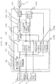
- Fig. 2 is a functional block diagram showing a configuration of a vehicle steering control apparatus including the electronic control unit furnished with a power-supply voltage monitoring function of the first embodiment.
- a vehicle steering control system to which is applied an electronic control unit 100 furnished with a power-supply voltage monitoring function of the invention is formed of a steering wheel 1 for use in steering wheels, a steering shaft 2 transmitting a rotation state of the steering wheel 1, a torque sensor 3 attached to the steering shaft 2 and detecting a steering torque applied to the steering wheel 1, a reduction gear 4 connected to one end of the steering shaft 2, a motor 5 connected to the reduction gear 4 and generating a steering assist torque, a vehicle steering control apparatus 10 driving the motor 5, a vehicle speed sensor 6 detecting a vehicle speed and transmitting the vehicle speed to the vehicle steering control apparatus 10, a battery 7 supplying the vehicle steering control apparatus 10 with power, and an ignition (IG) 8 supplied with power from the battery 7 and igniting an internal combustion engine.
- IG ignition
- the vehicle steering control apparatus 10 assists the steering of the steering wheel 1 by determining a steering assist torque on the basis of a torque detection value detected by the torque sensor 3 and a vehicle speed detection value of the vehicle speed sensor 6 and by driving the motor 5.
- the vehicle steering control apparatus 10 is formed of the electronic control unit 100 furnished with a power-supply voltage monitoring function of the first embodiment, a micro-controller 102, which is an electronic control portion controlling the motor 5 as an outside load, a power-supply supply portion 101 adjusting power from the battery 7, which is outside power, to an appropriate voltage and supplying the adjusted voltage to a power-supply supply terminal of the micro-controller 102, an inverter 104 supplying power to drive the motor 5, a gate driver 103 controlling the inverter 104 according to a command from the micro-controller 102, a motor relay 105 opening and closing a current-passing path between the inverter 104 and the motor 5, a motor relay driver 106 controlling the motor relay 105, and a monitoring control portion A 108a and a monitoring control portion B 108b monitoring a power-supply voltage of the power-supply supply portion 101.
- a micro-controller 102 which is an electronic control portion controlling the motor 5 as an outside load
- the electronic control unit 100 furnished with a power-supply voltage monitoring function of the first embodiment is a portion formed of the power-supply supply portion 101, the micro-controller 102, the monitoring control portion A 108a, and the monitoring control portion B 108b.
- the power-supply supply portion 101 adjusts power of the battery 7 to be an appropriate voltage within a normal operation range of the micro-controller, and supplies a constant voltage (for example, 5 V) necessary to operate the micro-controller 102 to the power-supply supply terminal of the micro-controller 102.
- a constant voltage for example, 5 V
- the micro-controller 102 performs predetermined arithmetic processing on the basis of a torque detection value detected by the torque sensor 3 and a vehicle speed detection value of the vehicle speed sensor 6 and determines a target current value (Ti1) to drive the motor 5.
- the micro-controller 102 then performs feedback control so that a detection current value (Mi) detected by a current detection circuit 107 coincides with the target current value (Ti1) and supplies a motor drive signal to the gate driver 103.
- the micro-controller 102 outputs a motor relay close command signal (energization) or a motor relay open command signal (de-energization) to the motor relay driver 106.
- the gate driver 103 outputs a signal to drive the inverter 104 to the inverter 104 according to the motor drive signal inputted therein from the micro-controller 102.
- the inverter 104 outputs a voltage to drive the motor 5 via the motor relay 105 according to the signal inputted therein from the gate driver 103.
- the motor relay 105 Upon input of the motor relay close command signal (energization) from the motor relay driver 106, the motor relay 105 energizes the current-passing path between the inverter 104 and the motor 5. Meanwhile, upon input of the motor relay open command signal (de-energization) from the motor relay driver 106, the motor relay 105 de-energizes the current-passing path between the inverter 104 and the motor 5.
- the motor relay driver 106 outputs the motor relay close command signal (energization) to the motor relay 105, and outputs the motor relay open command signal (de-energization) otherwise.
- the current detection circuit 107 detects a current flowing to the motor 5 and sends the detected current value (Mi) to the micro-controller 102.
- the first monitoring control portion A 108a monitors a power-supply voltage to be supplied to the micro-controller 102 and determines whether the power-supply voltage is a voltage within the normal operation range within which an operation of the micro-controller 102 is guaranteed. In the case where it is determined that the voltage is on the outside of the pre-set normal operation range, the power-supply voltage is determined as being abnormal, in which case the motor relay open command signal (de-energization) is outputted to the motor relay driver 106. Meanwhile, in the case where the power-supply voltage is determined as being normal, the motor relay close command signal (energization) is outputted to the motor relay driver 106.
- the second monitoring control portion B 108b also monitors the power-supply voltage to be supplied to the micro-controller 102 and determines whether the power-supply voltage is a voltage within the normal operation range within which an operation of the micro-controller 102 is guaranteed. In the case where it is determined that the voltage is on the outside of the pre-set normal operation range, the power-supply voltage is determined as being abnormal, in which case the motor relay open command signal (de-energization) is outputted to the motor relay driver 106. Meanwhile, in the case where the power-supply voltage is determined as being normal, the motor relay close command signal (energization) is outputted to the motor relay driver 106.
- independent two monitoring control portions (the first monitoring control portion A 108a and the second monitoring control portion B 108b) are provided for the micro-controller 102. Accordingly, even in the case where either one of the monitoring control portions fails, a power-supply voltage to be supplied to the micro-controller 102 is monitored by the other monitoring control portion. Hence, the driving of the motor can be stopped in a reliable manner in the event of an abnormality in the power-supply voltage. It thus becomes possible to prevent in a reliable manner that the steering is assisted abnormally due to an abnormal operation of the micro-controller 102 resulting from an abnormality in the power-supply voltage. In other words, higher reliability and safety can be ensured than by a method adopting the monitoring control in the related art.
- the monitoring control portions are provided on the outside of the micro-controller 102. This configuration makes it possible to stop the driving of the motor 5 as an outside load by bypassing the micro-controller 102. Accordingly, the driving of the motor 5 can be stopped in a reliable manner even in a circumstance where a voltage supplied to the micro-controller 102 goes out of the normal operation range and the micro-controller 102 no longer operates normally.
- the electronic control unit furnished with a power-supply voltage monitoring function of the first embodiment includes multiple monitoring control portions that monitor a power-supply voltage of the micro-controller.
- Fig. 3 is a functional block diagram showing a configuration of a vehicle steering control apparatus including an electronic control unit furnished with a power-supply voltage monitoring function of a second embodiment.
- a difference between the electronic control unit furnished with a power-supply voltage monitoring function of the second embodiment shown in Fig. 3 and the electronic control unit furnished with a power-supply voltage monitoring function of the first embodiment above shown in Fig. 2 is that the output of the first monitoring control portion A 108a is connected to the gate driver 103 that controls the inverter 104.
- the gate driver 103, the motor relay driver 106, and the monitoring control portion A 108a herein and a description is omitted for the rest of the components and operations thereof which are the same as those in the first embodiment above.
- a signal to drive the inverter 104 is outputted according to a motor drive signal outputted from the micro-controller 102.
- a drive stopping signal is inputted from the first monitoring control portion A 108a
- a signal to stop the inverter 104 is outputted to the inverter 104.
- a voltage to drive the motor 5 outputted from the inverter 104 is outputted or stopped according to the signals inputted from the gate driver 103.
- a motor relay close command signal (energization) is inputted into the motor relay driver 106 from both of the second monitoring control portion B 108b and the micro-controller 102
- the motor relay driver 106 outputs a motor relay close command signal (energization) to the motor relay 105 and outputs a motor relay open command signal (de-energization) otherwise.
- the first monitoring control portion A 108a monitors a power-supply voltage to be supplied to the micro-controller 102 and determines whether the power-supply voltage is a voltage within the normal operation range within which an operation of the micro-controller 102 is guaranteed. In the case where it is determined that the voltage is on the outside of the pre-set normal operation range, the power-supply voltage is determined as being abnormal, in which case a drive stopping signal for the inverter 104 is outputted to the gate driver 103. Meanwhile, in the case where the power-supply voltage is determined as being normal, an inverter drive signal is outputted to the gate driver 103.
- the first monitoring control portion A 108a controls the gate driver 103 to stop the inverter 104 by outputting a drive stopping signal and also the second monitoring control portion B 108b controls the motor relay driver 106 to de-energize the current-passing path between the inverter 104 and the motor 5 by outputting a motor relay open command signal (de-energization) (in other words, each of the monitoring control portions stops the driving of the motor 5 by acting on a different portion).
- an electronic control unit furnished with a power-supply voltage monitoring function of the second embodiment includes multiple monitoring control portions monitoring a power-supply voltage of the micro-controller and each of the monitoring control portions acts on a different outside load driver, so that in the case where the power-supply voltage goes out of the normal operation range, even when an inconvenience occurs in outside load stopping means by one monitoring control portion, the outside load can be stopped quickly in a reliable manner by outside load stopping means by the other monitoring control portion. It can be therefore expected a significant advantage that high reliability and safety can be ensured.
- Fig. 4A and Fig. 4B are respectively a view showing circuit configurations of voltage monitoring functions furnished to monitoring control portions of an electronic control unit furnished with a power-supply voltage monitoring function of a third embodiment.
- the third embodiment is configured in such a manner that the voltage monitoring functions furnished to the first monitoring control portion A 108a and the second monitoring control portion B 108b in the first embodiment and the second embodiment above are formed of different circuit networks.
- a description will be given to specific operations of the voltage monitoring functions furnished to the first monitoring control portion A 108a and the second monitoring control portion B 108b and a description is omitted for the rest of the components and operations thereof which are the same as those in the first embodiment or the second embodiment above.
- a voltage is monitored by making comparative voltages, a lower threshold voltage X [V] and an upper threshold voltage Y [V] in the normal operation range of a power-supply voltage, on the basis of a battery voltage (indicated by ⁇ ) and comparing these comparative voltages with a power-supply voltage of 5 V (indicated by O) to be supplied to the micro-controller 102.
- a battery voltage indicated by ⁇
- a power-supply voltage of 5 V indicated by O
- Vcc a power-supply voltage
- the voltage monitoring functions furnished to the monitoring control portion A 108a and the monitoring control portion B 108b are formed of different circuit networks (in other words, designed for different circuit operations).
- the voltage monitoring function furnished to one monitoring control portion fails to function as intended, it is possible to continue to monitor the power-supply voltage by the voltage monitoring function furnished to the other monitoring control portion.
- the voltage monitoring functions of different circuit designs it becomes possible to avoid the occurrence of inconveniences in the voltage monitoring functions furnished to the monitoring control portion A 108a and the monitoring control portion B 108b at the same time due to a systematic failure.
- the electronic control unit furnished with a power-supply voltage monitoring function of the third embodiment includes multiple monitoring control portions monitoring a power-supply voltage of the micro-controller and the voltage monitoring functions furnished to the respective control monitoring portions are formed of different circuit networks, so that in the case where the power-supply voltage goes out of the normal operation range of the micro-controller, even when the voltage monitoring function furnished to one monitoring control portion fails to function as intended due to some inconvenience on the circuit, it becomes possible to continue to monitor the power-supply voltage by the voltage monitoring function furnished to the other monitoring control portion. It can be therefore expected a significant advantage that high reliability and safety can be ensured for the voltage monitoring functions furnished to the monitoring control portions.
- Fig. 5 is a functional block diagram showing a configuration of a vehicle steering control apparatus including an electronic control unit furnished with a power-supply voltage monitoring function of a fourth embodiment.
- a micro-controller B 109 which is a secondary electronic control portion, is additionally provided and that the function furnished to the first monitoring control portion A 108a of Fig. 3 is taken over by a monitoring control portion A1 110a and a monitoring control portion A2 111a and the function furnished to the second monitoring control portion B 108b is taken over by a monitoring control portion B1 110b and a monitoring control portion B2 111b.
- the micro-controller B 109 monitors an operation of the micro-controller 102, which is the main electronic control portion.
- a vehicle steering control apparatus is furnished with various fail-safe functions in order to forestall an accident triggered by a failure and there may be a case where the steering control apparatus is provided with a micro-controller to realize the fail-safe functions apart from the micro-controller that outputs a control signal to control the motor (for example, WO2007/138676 ).
- the fourth embodiment will describe a case where an electronic control unit furnished with a power-supply voltage monitoring function provided with the micro-controller B 109 is applied to a vehicle steering controlapparatus.
- the monitoring control portion A1 110a is built in the power-supply supply portion 101 and monitors a voltage lower than the normal operation range of a power-supply voltage to be supplied to the micro-controller 102 using its voltage monitoring function. In the case where the power-supply voltage is a voltage lower than a pre-set lower threshold voltage, the monitoring control portion A1 110a determines that the power-supply voltage is abnormal and outputs a reset signal to the micro-controller 102.
- the monitoring control portion A1 110a determines that the power-supply voltage is abnormal, the monitoring control portion A1 110a acts on the gate driver 103 to stop the driving of the inverter 104 by resetting the micro-controller 102 so that an output of the micro-controller 102 is changed to high impedance.
- the monitoring control portion A2 111a monitors a voltage higher than the normal operation range of the power-supply voltage to be supplied to the micro-controller 102 using its voltage monitoring function.
- the monitoring control portion A2 111a determines that the power-supply voltage is abnormal and outputs a drive stopping signal to the gate driver 103.
- the monitoring control portion A2 111a determines that the power-supply voltage is normal, the monitoring control portion A2 111a outputs a drive enabling signal to the gate driver 103.
- the monitoring control portion B1 110b is built in the micro-controller B 109 and monitors a voltage lower than the normal operation range of a power-supply voltage to be supplied to the micro-controller 102 using its voltage monitoring function. In the case where the power-supply voltage is a voltage lower than a pre-set lower threshold voltage, the monitoring control portion B1 110b determines that the power-supply voltage is abnormal and outputs a motor relay open command signal (de-energization) to the motor relay driver 106.
- the monitoring control portion B2 111b monitors a voltage higher than the normal operation range of a power-supply voltage to be supplied to the micro-controller 102 using its voltage monitoring function. In the case where the power-supply voltage is a voltage higher than a pre-set upper threshold voltage, the monitoring control portion B2 111b determines that the power-supply voltage is abnormal and outputs a motor relay open command signal (de-energization) to the motor relay driver 106.
- independent two monitoring control portions (the monitoring control portion A1 110a and the monitoring control portion B1 110b) furnished with a voltage monitoring function for the lower threshold voltage of the power-supply voltage and independent two monitoring control portions (the monitoring control portion A2 111a and the monitoring control portion B2 111b) furnished with a voltage monitoring function for the upper threshold voltage are provided for the micro-controller 102.
- a power-supply voltage to be supplied to the micro-controller 102 is monitored by the voltage monitoring functions furnished to the rest of the monitoring control portions. It thus becomes possible to stop the driving of the motor in a reliable manner in the event of an abnormality in the power-supply voltage.
- the electronic control unit furnished with a power-supply voltage monitoring function of the fourth embodiment includes multiple monitoring control portions monitoring a power-supply voltage of the micro-controller, independent two monitoring control portions furnished with a voltage monitoring function of monitoring whether the power-supply voltage is lower than a lower threshold voltage of the power-supply voltage, and independent two monitoring control portions furnished with a voltage monitoring function of monitoring whether the power-supply voltage is higher than an upper threshold voltage.
- each monitoring control portion can be of a simpler configuration. It thus becomes possible to lower the probability of a failure that the monitoring function is lost. In short, further higher reliability can be ensured.
- the voltage monitoring function furnished to the monitoring control portion A1 110a monitoring whether the power-supply voltage is lower than the lower threshold voltage and the voltage monitoring function furnished to the monitoring control portion A2 111a monitoring whether the power-supply voltage is higher than the upper threshold voltage act on the gate driver 103 so as to stop the driving of the inverter 104
- the monitoring control portion B1 110b monitoring whether the power-supply voltage is lower than the lower threshold voltage and the monitoring control portion B2 111b monitoring whether the power-supply voltage is higher than the upper threshold voltage act on the motor relay driver 106 so that the motor relay 105 de-energizes the current-passing path between the inverter 104 and the motor 5.
- the driving of the motor 5 can be stopped by the other motor driving stopping means (means for stopping the driving of the inverter 104).
- the cost can be reduced in comparison with a case where the monitoring control portion A1 110a is provided on the outside of the power-supply supply portion 101.
- the cost can be reduced in comparison with a case where the monitoring control portion B1 110b is provided on the outside of the micro-controller B 109.
- the voltage monitoring function furnished to the monitoring control portion A1 110a monitoring whether the power-supply voltage is lower than the lower threshold voltage stops the driving of the motor 5 by inputting a reset signal to the reset terminal of the micro-controller 102 upon detection of an abnormality in the power-supply voltage.
- the cost can be reduced in comparison with a case where the driving of the motor 5 is stopped by bypassing the micro-controller 102.
- the monitoring control portion A1 110a and the monitoring control portion B1 110b monitoring whether the power-supply voltage is lower than the lower threshold voltage use the voltage monitoring functions for the lower threshold voltage built in the power-supply supply portion 101 and the micro-controller B 109, respectively, the monitoring control portion A1 110a and the monitoring control portion B1 110b are formed of different circuit networks (that is, different circuit designs). Hence, for example, even in the case where one monitoring control portion fails to function as intended due to a design inconvenience, the monitoring of the power-supply voltage can be continued by the other monitoring control portion. In other words, by adopting different circuit designs, it becomes possible to avoid the occurrence of inconveniences in the monitoring control portions A1 110a and the monitoring control portion B1 110b at the same time due to a systematic failure.
- the monitoring control portion A2 111a and the monitoring control portion B2 111b monitoring whether the power-supply voltage is higher than the upper threshold voltage stop the driving of the motor 5 as an outside load by bypassing the micro-controller 102.
- Fig. 6 is a view showing a circuit configuration of voltage monitoring functions furnished to monitoring control portions of an electronic control unit furnished with a power-supply voltage monitoring function of a fifth embodiment.
- the fifth embodiment is configured in such a manner that the voltage monitoring functions furnished to the monitoring control portion A2 111a and the monitoring control portion B2 111b in the fourth embodiment above are formed of identical circuit networks using different circuit parts.
- a description will be given to specific operations of the voltage monitoring functions furnished to the monitoring control portion A2 111a and the monitoring control portion B2 111b and a description is omitted for the rest of the components and operations thereof which are the same as those in the fourth embodiment above.
- the monitoring control portion A2 111a and the monitoring control portion B2 111b are furnished with the identical functions but have internal configurations different from each other.
- the respective circuit networks are of a simple circuit design as is shown in Fig. 6 and each circuit is formed using different parts (for example, parts available from different manufacturers).
- the voltage monitoring function for the upper threshold voltage Y [V] of Fig. 6 is realized by a circuit design different from the circuit networks of the third embodiment shown in Fig. 4A and Fig. 4B .
- the monitoring control portion A2 111a and the monitoring control portion B2 111b monitoring a high voltage are formed of identical circuit networks but parts used for each circuit are different (for example, parts available from different manufacturers are used). It thus becomes possible to avoid a situation in which the voltage monitoring functions furnished to the monitoring control portion A2 111a and the monitoring control portion B2 111b are lost at the same time due to a design-originated inconvenience or a lot-originated deficiency of the parts themselves.
- the electronic control unit furnished with a power-supply voltage monitoring function of the fifth embodiment includes multiple monitoring control portions monitoring a power-supply voltage of the micro-controller and circuits in the respective circuit networks forming the voltage monitoring functions furnished to the multiple monitoring control portions are formed using different parts.
- the driving of the inverter 104 is stopped via the gate deriver 103. It is, however, also possible to adopt a method by which a power-supply relay is disposed in a power supply path from the battery 7 to the inverter 104 and the driving of the inverter 104 is stopped by opening this power-supply relay by the power-supply relay driver from one monitoring control portion.
- the fourth embodiment above it is configured in such a manner that a power-supply voltage to be supplied to the micro-controller 102 is monitored by the monitoring control portion B1 110b built in the micro-controller B 109, and in the case where the power-supply voltage is a voltage lower than the pre-set lower threshold voltage, it is determined that the power-supply voltage is abnormal, so that a motor relay open command signal (de-energization) is outputted to the motor relay driver 106.
- the driving of the motor 5 is stopped by resetting the micro-controller B 109 to change an output of the micro-controller B 109 to high impedance so that the micro-controller B 109 acts on the motor relay driver 106.
- the monitoring control portion A2 111a and the monitoring control portion B2 111b monitoring whether a power-supply voltage to be supplied to the micro-controller 102 is higher than the upper threshold voltage are independent circuits.
- it may be configured in such a manner that, for example, the gate driver 103 is formed of an IC and the monitoring control portion A2 111a is built in this IC.
- the monitoring control portion A2 111a and the monitoring control portion B2 111b monitoring whether a power-supply voltage to be supplied to the micro-controller 102 is higher than the upper threshold voltage are formed of identical circuit networks. It should be appreciated, however, that these control portions may be formed of different circuit networks.
- the functional safety standards ISO26262 subject to automobiles require considerations of multiple failures.
- the electronic control unit furnished with a power-supply voltage monitoring function of the invention to a system performing control relating to the steering, braking, and running that influence a vehicle behavior using the micro-controller, it becomes possible to form an electronic control unit furnished with a power-supply voltage monitoring function and capable of maintaining high reliability and safety even when multiple failures are taken into consideration.
- the outside load driver controlling the outside load may be formed integrally with the outside load, in which case the outside load controlling function outputs a command signal to the outside load.
Landscapes
- Engineering & Computer Science (AREA)
- Chemical & Material Sciences (AREA)
- Combustion & Propulsion (AREA)
- Transportation (AREA)
- Mechanical Engineering (AREA)
- Power Engineering (AREA)
- Electromagnetism (AREA)
- General Physics & Mathematics (AREA)
- Radar, Positioning & Navigation (AREA)
- Automation & Control Theory (AREA)
- Physics & Mathematics (AREA)
- Power Steering Mechanism (AREA)
- Control Of Electric Motors In General (AREA)
Claims (9)
- Elektronische Steuereinheit (100) für eine Fahrzeuglenkvorrichtung und ausgestattet mit einer Stromversorgung-Spannungsüberwachungsfunktion, umfassend:einen elektronischen Steuerabschnitt (102), der eine Außenlast (5) steuert;einen Stromversorgung-Versorgungsabschnitt (101), der eine Spannung einer Außenstromversorgung, die an einem Stromversorgung-Versorgungsanschluss des elektronischen Steuerabschnitts (102) anzulegen ist, auf eine Spannung innerhalb eines normalen Betriebsbereichs des elektronischen Steuerabschnitts (102) anpasst und die angepasste Spannung anlegt; undmehrere Überwachungssteuerabschnitte (108a, 108b, 110a, 110b, 111a und 111b), von denen jeder mit einer Spannungsüberwachungsfunktion zum Überwachen einer Spannung des Stromversorgung-Versorgungsabschnitts (101) und einer Außenlast-Steuerfunktion zum Steuern der Außenlast (5) entsprechend einem Ergebnis der Spannungsüberwachung ausgestattet ist, wobeifalls die Spannungsüberwachungsfunktion, mit der einer der mehreren Überwachungssteuerabschnitte (108a, 108b, 110a, 110b, 111a und 111b) ausgestattet ist, erfasst, dass die Spannung außerhalb des normalen Betriebsbereichs des elektronischen Steuerabschnitts (102) ist, ein Außenlast-Treiber (106), der die Außenlast (5) steuert, durch eine Außenlast-Steuerfunktion gestoppt wird, dadurch gekennzeichnet, dass die Außenlast-Steuerfunktionen eingerichtet sind zum Stoppen des die Außenlast (5) steuernden Außenlast-Treibers (106) durch Umgehen des elektronischen Steuerabschnitts (102); unddie Außenlast-Steuerfunktionen, mit der die mehreren Überwachungssteuerabschnitte (108a, 108b, 110a, 110b, 111a und 111b) ausgestattet sind, auf den Außenlast-Treiber (106) unabhängig voneinander einwirken.
- Elektronische Steuereinheit (100), die mit einer Stromversorgung-Spannungsüberwachungsfunktion ausgestattet ist, nach Anspruch 1, dadurch gekennzeichnet, dass:zumindest eine der Außenlast-Steuerfunktionen über den elektronischen Steuerabschnitt (102) den Außenlast-Treiber (106) stoppt durch Eingeben eines Rücksetzsignals in einen Rücksetzanschluss des elektronischen Steuerabschnitts (102).
- Elektronische Steuereinheit (100), die mit einer Stromversorgung-Spannungsüberwachungsfunktion ausgestattet ist, nach Anspruch 1, dadurch gekennzeichnet, dass:falls durch die Spannungsüberwachungsfunktion bestimmt wird, dass die Spannung höher als eine obere Schwellwertspannung des normalen Betriebsbereichs ist, die Außenlast-Steuerfunktion den Außenlast-Treiber (106) durch Umgehen des elektronischen Steuerabschnitts (102) stoppt.
- Elektronische Steuereinheit (100), die mit einer Stromversorgung-Spannungsüberwachungsfunktion ausgestattet ist, nach einem der Ansprüche 1 bis 3, dadurch gekennzeichnet, dass:die mehreren Überwachungssteuerabschnitte (108a, 108b, 110a, 110b, 111a und 111b) voneinander verschiedene Schaltungskonfigurationen aufweisen.
- Elektronische Steuereinheit (100), die mit einer Stromversorgung-Spannungsüberwachungsfunktion ausgestattet ist, nach einem der Ansprüche 1 bis 3, dadurch gekennzeichnet, dass:die mehreren Überwachungssteuerabschnitte (108a, 108b, 110a, 110b, 111a und 111b) aus voneinander verschiedenen Schaltungsteilen ausgebildet sind.
- Elektronische Steuereinheit (100), die mit einer Stromversorgung-Spannungsüberwachungsfunktion ausgestattet ist, nach einem der Ansprüche 1 bis 4, dadurch gekennzeichnet, dass:einer der mehreren Überwachungssteuerabschnitte (108a, 108b, 110a, 110b, 111a und 111b) an dem Stromversorgung-Versorgungsabschnitt (101) bereitgestellt wird.
- Elektronische Steuereinheit (100), die mit einer Stromversorgung-Spannungsüberwachungsfunktion ausgestattet ist, nach einem der Ansprüche 1 bis 4, dadurch gekennzeichnet, dass:einer der mehreren Überwachungssteuerabschnitte (108a, 108b, 110a, 110b, 111a und 111b) an dem Außenlast-Treiber (106) bereitgestellt wird.
- Elektronische Steuereinheit (100), die mit einer Stromversorgung-Spannungsüberwachungsfunktion ausgestattet ist, nach einem der Ansprüche 1 bis 4, dadurch gekennzeichnet, dass:der elektronische Steuerabschnitt (102) einen Hauptelektronik-Steuerabschnitt (102) und einen Sekundärelektronik-Steuerabschnitt (109) enthält; undeiner der mehreren Überwachungssteuerabschnitte (108a, 108b, 110a, 110b, 111a und 111b) an dem Sekundärelektronik-Steuerabschnitt (109) bereitgestellt wird.
- Fahrzeuglenk-Steuervorrichtung (10), gekennzeichnet durch Enthalten der elektronischen Steuereinheit (100), die mit einer Stromversorgung-Spannungsüberwachungsfunktion ausgestattet ist, nach einem der Ansprüche 1 bis 8,
wobei die Fahrzeuglenk-Steuervorrichtung (100) dadurch gekennzeichnet ist, dass:ein durch den elektronischen Steuerabschnitt (102) zu steuernder Gegenstand ein Motor (5) und ein Inverter (104), der Strom zum Antreiben des Motors (5) liefert, ist; undder Außenlast-Treiber (106) ein Stromversorgungrelais-Treiber ist, der ein Stromversorgungrelais, das einen Stromversorgungspfad für den Inverter (104) öffnet und schließt, einen den Inverter (104) steuernden Gate-Treiber (103) und einen Motorrelaistreiber (106) steuert, der ein Motorrelais (105) steuert, das einen Stromdurchlasspfad zwischen dem Inverter (104) und dem Motor (5) öffnet und schließt.
Applications Claiming Priority (1)
| Application Number | Priority Date | Filing Date | Title |
|---|---|---|---|
| PCT/JP2011/078057 WO2013084277A1 (ja) | 2011-12-05 | 2011-12-05 | 電源電圧監視機能を有する電子制御装置及びそれを備えた車両ステアリング制御装置 |
Publications (3)
| Publication Number | Publication Date |
|---|---|
| EP2790318A1 EP2790318A1 (de) | 2014-10-15 |
| EP2790318A4 EP2790318A4 (de) | 2015-07-22 |
| EP2790318B1 true EP2790318B1 (de) | 2017-03-15 |
Family
ID=48573685
Family Applications (1)
| Application Number | Title | Priority Date | Filing Date |
|---|---|---|---|
| EP11877153.4A Active EP2790318B1 (de) | 2011-12-05 | 2011-12-05 | Elektronische steuerungsvorrichtung mit versorgungsspannungsüebrwachungsfunktion und fahrzeuglenkungssteuerungsvorrichtung damit |
Country Status (5)
| Country | Link |
|---|---|
| US (1) | US9981684B2 (de) |
| EP (1) | EP2790318B1 (de) |
| JP (1) | JP5752266B2 (de) |
| KR (3) | KR101773314B1 (de) |
| WO (1) | WO2013084277A1 (de) |
Families Citing this family (12)
| Publication number | Priority date | Publication date | Assignee | Title |
|---|---|---|---|---|
| DE102011089556A1 (de) * | 2011-12-22 | 2013-06-27 | Robert Bosch Gmbh | Vorrichtung und Verfahren zur Überwachung einer Spannungsversorgung für ein Fahrzeugsystem |
| JP5951429B2 (ja) * | 2012-02-01 | 2016-07-13 | ルネサスエレクトロニクス株式会社 | ウォッチドッグ回路、電源ic、及びウォッチドッグ監視システム |
| WO2016047284A1 (ja) * | 2014-09-24 | 2016-03-31 | 日立オートモティブシステムズステアリング株式会社 | 車両搭載機器の制御装置およびパワーステアリング装置 |
| KR102281672B1 (ko) * | 2015-04-02 | 2021-07-27 | 주식회사 만도 | Eps 전자제어장치 및 제어방법 |
| DE102016010777B4 (de) | 2016-04-12 | 2023-03-30 | Sew-Eurodrive Gmbh & Co Kg | Antrieb mit Sicherheitsschaltvorrichtung, System und Verfahren |
| US10752115B2 (en) * | 2017-09-19 | 2020-08-25 | Ford Global Technologies, Llc | Contactor supply bus |
| JP7010663B2 (ja) * | 2017-10-27 | 2022-01-26 | ローム株式会社 | 監視装置 |
| JP7010058B2 (ja) * | 2018-02-26 | 2022-01-26 | 株式会社ジェイテクト | 操舵制御装置 |
| FR3083398B1 (fr) * | 2018-06-28 | 2020-08-21 | Valeo Equip Electr Moteur | Systeme de commande d'un interrupteur, bras de commutation et installation electrique |
| FR3083396B1 (fr) * | 2018-06-28 | 2020-08-21 | Valeo Equip Electr Moteur | Systeme de commande d'un interrupteur, bras de commutation et installation electrique |
| EP3968128A1 (de) * | 2020-09-15 | 2022-03-16 | NXP USA, Inc. | Verfahren, vorrichtung und computerprogramm zur überprüfung der leistungsversorgungsüberwachung |
| JP7647377B2 (ja) * | 2021-06-22 | 2025-03-18 | 株式会社アイシン | シフト装置および車両用モータ制御装置 |
Family Cites Families (25)
| Publication number | Priority date | Publication date | Assignee | Title |
|---|---|---|---|---|
| US5315533A (en) * | 1991-05-17 | 1994-05-24 | Best Power Technology, Inc. | Back-up uninterruptible power system |
| JP3096793B2 (ja) * | 1992-07-28 | 2000-10-10 | 光洋精工株式会社 | 電動パワーステアリング装置 |
| US5360077A (en) | 1992-06-01 | 1994-11-01 | Koyo Seiko Co., Ltd. | Electric power steering apparatus |
| US5465011A (en) * | 1992-12-14 | 1995-11-07 | Square D Company | Uninterruptible power supply with improved output regulation |
| US5737168A (en) * | 1995-05-04 | 1998-04-07 | Baker; George T. | Electrical power management system |
| JPH1051954A (ja) | 1996-07-30 | 1998-02-20 | Mitsubishi Electric Corp | 電子機器の停電検出方法及び停電検出装置 |
| JPH1172528A (ja) | 1997-08-28 | 1999-03-16 | Takaoka Electric Mfg Co Ltd | 制御回路の地絡判定回路 |
| JP2000023483A (ja) | 1998-07-01 | 2000-01-21 | Ricoh Co Ltd | スキャナモ−タ制御装置 |
| KR100695402B1 (ko) | 2002-05-08 | 2007-03-15 | 주식회사 만도 | 전동식 파워스티어링 장치의 고장안전장치 |
| US7259477B2 (en) * | 2003-08-15 | 2007-08-21 | American Power Conversion Corporation | Uninterruptible power supply |
| JP2007520180A (ja) * | 2003-10-14 | 2007-07-19 | ブラック アンド デッカー インク | 電池パックの障害状態からの保護を提供するべく適合された二次電池、電動工具、充電器、及び電池パック用の保護方法、保護回路、及び保護装置 |
| JP4340966B2 (ja) | 2004-01-22 | 2009-10-07 | 株式会社デンソー | マイコン電源電圧監視システム |
| JP4254577B2 (ja) | 2004-03-04 | 2009-04-15 | 株式会社デンソー | 制御装置 |
| JP4617716B2 (ja) * | 2004-05-11 | 2011-01-26 | 株式会社ジェイテクト | 電動パワーステアリング装置 |
| JP4896722B2 (ja) | 2006-05-30 | 2012-03-14 | 三菱電機株式会社 | ステアリング制御装置 |
| FR2911736B1 (fr) * | 2007-01-23 | 2009-03-20 | Schneider Toshiba Inverter | Dispositif de commande d'un interrupteur de puissance et variateur comprenant un tel dipositif. |
| DE102007006966A1 (de) * | 2007-02-13 | 2008-08-14 | Robert Bosch Gmbh | Antriebseinrichtung zum Antreiben von mehreren Achsen |
| WO2008146372A1 (ja) | 2007-05-30 | 2008-12-04 | Mitsubishi Electric Corporation | 車両用操舵装置 |
| US8000873B2 (en) * | 2008-05-12 | 2011-08-16 | Wabtec Holding Corp. | Braking system |
| JP2009287414A (ja) * | 2008-05-27 | 2009-12-10 | Yokogawa Electric Corp | 冷却ファン装置およびこの冷却ファン装置を備えたジルコニア式酸素計 |
| JP2010074915A (ja) * | 2008-09-17 | 2010-04-02 | Jtekt Corp | モータ制御装置及び電動パワーステアリング装置 |
| CN102348592B (zh) * | 2009-04-21 | 2014-08-06 | 丰田自动车株式会社 | 行驶辅助装置 |
| JP5020307B2 (ja) | 2009-12-07 | 2012-09-05 | 三菱電機株式会社 | 電気負荷の駆動制御装置 |
| JP5225314B2 (ja) * | 2010-03-31 | 2013-07-03 | 日本航空電子工業株式会社 | モータ制御装置とその故障検出方法 |
| JP5409692B2 (ja) * | 2011-04-18 | 2014-02-05 | 三菱電機株式会社 | 電動パワーステアリング装置 |
-
2011
- 2011-12-05 KR KR1020167023527A patent/KR101773314B1/ko not_active Expired - Fee Related
- 2011-12-05 JP JP2013547971A patent/JP5752266B2/ja active Active
- 2011-12-05 WO PCT/JP2011/078057 patent/WO2013084277A1/ja not_active Ceased
- 2011-12-05 KR KR1020147009781A patent/KR20140069145A/ko not_active Ceased
- 2011-12-05 EP EP11877153.4A patent/EP2790318B1/de active Active
- 2011-12-05 KR KR1020167023530A patent/KR101773315B1/ko not_active Expired - Fee Related
- 2011-12-05 US US14/344,101 patent/US9981684B2/en active Active
Non-Patent Citations (1)
| Title |
|---|
| None * |
Also Published As
| Publication number | Publication date |
|---|---|
| KR101773314B1 (ko) | 2017-08-31 |
| EP2790318A4 (de) | 2015-07-22 |
| JP5752266B2 (ja) | 2015-07-22 |
| JPWO2013084277A1 (ja) | 2015-04-27 |
| KR20140069145A (ko) | 2014-06-09 |
| KR101773315B1 (ko) | 2017-08-31 |
| US20140350791A1 (en) | 2014-11-27 |
| WO2013084277A1 (ja) | 2013-06-13 |
| US9981684B2 (en) | 2018-05-29 |
| KR20160104746A (ko) | 2016-09-05 |
| KR20160105924A (ko) | 2016-09-07 |
| EP2790318A1 (de) | 2014-10-15 |
Similar Documents
| Publication | Publication Date | Title |
|---|---|---|
| EP2790318B1 (de) | Elektronische steuerungsvorrichtung mit versorgungsspannungsüebrwachungsfunktion und fahrzeuglenkungssteuerungsvorrichtung damit | |
| US11126176B2 (en) | Vehicle control apparatus | |
| US11201498B2 (en) | Power supply system | |
| US9975572B2 (en) | In-vehicle device controller and power steering device | |
| JP5117614B2 (ja) | 鉄道車両用ドア制御システム | |
| WO2015068491A1 (ja) | 車両の制御装置及びフェイルセーフ方法 | |
| CN111791943A (zh) | 旋转电机控制装置和使用其的电动助力转向设备 | |
| WO2013001716A1 (ja) | 車載電子制御装置 | |
| CN104918829A (zh) | 车载电源控制器 | |
| JP2003182608A (ja) | 電動パワーステアリング制御装置 | |
| US20120235472A1 (en) | Power source control device and method, and power management system | |
| US10606252B2 (en) | Control device including one microcomputer for controlling a motor vehicle which may immediately stop rotations of the motor when an abnormal condition occurs | |
| EP3460993B1 (de) | Elektronische steuerungsvorrichtung mit mehreren systemschaltungen | |
| JP2013256143A (ja) | 電動パワーステアリング制御装置 | |
| JP7147691B2 (ja) | 電子制御装置 | |
| KR101791287B1 (ko) | 차량의 조향장치 및 그의 제어방법 | |
| KR20170114827A (ko) | 스마트 pra의 안전 회로 | |
| JP2004338657A (ja) | 車両用操舵装置 | |
| KR102693290B1 (ko) | 전동식 파워 스티어링 시스템 및 그 제어 방법 | |
| JP7620723B2 (ja) | 電子制御装置および電子制御装置の診断方法 | |
| JP2020123207A (ja) | 制御装置 | |
| JP2013241030A (ja) | 電動パワーステアリング装置 | |
| KR20170027186A (ko) | 전자식 능동형 스테빌라이저 시스템의 제어 장치 및 제어 방법 | |
| HK1164806B (en) | Door control system for railroad vehicle |
Legal Events
| Date | Code | Title | Description |
|---|---|---|---|
| PUAI | Public reference made under article 153(3) epc to a published international application that has entered the european phase |
Free format text: ORIGINAL CODE: 0009012 |
|
| 17P | Request for examination filed |
Effective date: 20140227 |
|
| AK | Designated contracting states |
Kind code of ref document: A1 Designated state(s): AL AT BE BG CH CY CZ DE DK EE ES FI FR GB GR HR HU IE IS IT LI LT LU LV MC MK MT NL NO PL PT RO RS SE SI SK SM TR |
|
| DAX | Request for extension of the european patent (deleted) | ||
| RA4 | Supplementary search report drawn up and despatched (corrected) |
Effective date: 20150619 |
|
| RIC1 | Information provided on ipc code assigned before grant |
Ipc: H02P 29/02 20060101AFI20150615BHEP Ipc: B62D 6/00 20060101ALI20150615BHEP Ipc: H02H 7/09 20060101ALI20150615BHEP Ipc: H02H 9/04 20060101ALI20150615BHEP Ipc: B62D 5/04 20060101ALI20150615BHEP |
|
| RIC1 | Information provided on ipc code assigned before grant |
Ipc: B62D 5/04 20060101ALI20160812BHEP Ipc: B62D 6/00 20060101ALI20160812BHEP Ipc: H02H 9/04 20060101ALI20160812BHEP Ipc: H02P 29/02 20060101AFI20160812BHEP Ipc: H02H 7/09 20060101ALI20160812BHEP Ipc: H02P 29/024 20160101ALI20160812BHEP |
|
| GRAP | Despatch of communication of intention to grant a patent |
Free format text: ORIGINAL CODE: EPIDOSNIGR1 |
|
| INTG | Intention to grant announced |
Effective date: 20160929 |
|
| GRAJ | Information related to disapproval of communication of intention to grant by the applicant or resumption of examination proceedings by the epo deleted |
Free format text: ORIGINAL CODE: EPIDOSDIGR1 |
|
| GRAR | Information related to intention to grant a patent recorded |
Free format text: ORIGINAL CODE: EPIDOSNIGR71 |
|
| GRAS | Grant fee paid |
Free format text: ORIGINAL CODE: EPIDOSNIGR3 |
|
| GRAA | (expected) grant |
Free format text: ORIGINAL CODE: 0009210 |
|
| INTC | Intention to grant announced (deleted) | ||
| INTG | Intention to grant announced |
Effective date: 20170202 |
|
| AK | Designated contracting states |
Kind code of ref document: B1 Designated state(s): AL AT BE BG CH CY CZ DE DK EE ES FI FR GB GR HR HU IE IS IT LI LT LU LV MC MK MT NL NO PL PT RO RS SE SI SK SM TR |
|
| REG | Reference to a national code |
Ref country code: CH Ref legal event code: EP Ref country code: GB Ref legal event code: FG4D |
|
| REG | Reference to a national code |
Ref country code: IE Ref legal event code: FG4D |
|
| REG | Reference to a national code |
Ref country code: AT Ref legal event code: REF Ref document number: 876490 Country of ref document: AT Kind code of ref document: T Effective date: 20170415 |
|
| REG | Reference to a national code |
Ref country code: DE Ref legal event code: R096 Ref document number: 602011036103 Country of ref document: DE |
|
| REG | Reference to a national code |
Ref country code: NL Ref legal event code: MP Effective date: 20170315 |
|
| REG | Reference to a national code |
Ref country code: LT Ref legal event code: MG4D |
|
| PG25 | Lapsed in a contracting state [announced via postgrant information from national office to epo] |
Ref country code: HR Free format text: LAPSE BECAUSE OF FAILURE TO SUBMIT A TRANSLATION OF THE DESCRIPTION OR TO PAY THE FEE WITHIN THE PRESCRIBED TIME-LIMIT Effective date: 20170315 Ref country code: FI Free format text: LAPSE BECAUSE OF FAILURE TO SUBMIT A TRANSLATION OF THE DESCRIPTION OR TO PAY THE FEE WITHIN THE PRESCRIBED TIME-LIMIT Effective date: 20170315 Ref country code: GR Free format text: LAPSE BECAUSE OF FAILURE TO SUBMIT A TRANSLATION OF THE DESCRIPTION OR TO PAY THE FEE WITHIN THE PRESCRIBED TIME-LIMIT Effective date: 20170616 Ref country code: NO Free format text: LAPSE BECAUSE OF FAILURE TO SUBMIT A TRANSLATION OF THE DESCRIPTION OR TO PAY THE FEE WITHIN THE PRESCRIBED TIME-LIMIT Effective date: 20170615 Ref country code: LT Free format text: LAPSE BECAUSE OF FAILURE TO SUBMIT A TRANSLATION OF THE DESCRIPTION OR TO PAY THE FEE WITHIN THE PRESCRIBED TIME-LIMIT Effective date: 20170315 |
|
| REG | Reference to a national code |
Ref country code: AT Ref legal event code: MK05 Ref document number: 876490 Country of ref document: AT Kind code of ref document: T Effective date: 20170315 |
|
| PG25 | Lapsed in a contracting state [announced via postgrant information from national office to epo] |
Ref country code: RS Free format text: LAPSE BECAUSE OF FAILURE TO SUBMIT A TRANSLATION OF THE DESCRIPTION OR TO PAY THE FEE WITHIN THE PRESCRIBED TIME-LIMIT Effective date: 20170315 Ref country code: LV Free format text: LAPSE BECAUSE OF FAILURE TO SUBMIT A TRANSLATION OF THE DESCRIPTION OR TO PAY THE FEE WITHIN THE PRESCRIBED TIME-LIMIT Effective date: 20170315 Ref country code: BG Free format text: LAPSE BECAUSE OF FAILURE TO SUBMIT A TRANSLATION OF THE DESCRIPTION OR TO PAY THE FEE WITHIN THE PRESCRIBED TIME-LIMIT Effective date: 20170615 Ref country code: SE Free format text: LAPSE BECAUSE OF FAILURE TO SUBMIT A TRANSLATION OF THE DESCRIPTION OR TO PAY THE FEE WITHIN THE PRESCRIBED TIME-LIMIT Effective date: 20170315 |
|
| PG25 | Lapsed in a contracting state [announced via postgrant information from national office to epo] |
Ref country code: NL Free format text: LAPSE BECAUSE OF FAILURE TO SUBMIT A TRANSLATION OF THE DESCRIPTION OR TO PAY THE FEE WITHIN THE PRESCRIBED TIME-LIMIT Effective date: 20170315 |
|
| PG25 | Lapsed in a contracting state [announced via postgrant information from national office to epo] |
Ref country code: AT Free format text: LAPSE BECAUSE OF FAILURE TO SUBMIT A TRANSLATION OF THE DESCRIPTION OR TO PAY THE FEE WITHIN THE PRESCRIBED TIME-LIMIT Effective date: 20170315 Ref country code: ES Free format text: LAPSE BECAUSE OF FAILURE TO SUBMIT A TRANSLATION OF THE DESCRIPTION OR TO PAY THE FEE WITHIN THE PRESCRIBED TIME-LIMIT Effective date: 20170315 Ref country code: CZ Free format text: LAPSE BECAUSE OF FAILURE TO SUBMIT A TRANSLATION OF THE DESCRIPTION OR TO PAY THE FEE WITHIN THE PRESCRIBED TIME-LIMIT Effective date: 20170315 Ref country code: RO Free format text: LAPSE BECAUSE OF FAILURE TO SUBMIT A TRANSLATION OF THE DESCRIPTION OR TO PAY THE FEE WITHIN THE PRESCRIBED TIME-LIMIT Effective date: 20170315 Ref country code: SK Free format text: LAPSE BECAUSE OF FAILURE TO SUBMIT A TRANSLATION OF THE DESCRIPTION OR TO PAY THE FEE WITHIN THE PRESCRIBED TIME-LIMIT Effective date: 20170315 Ref country code: EE Free format text: LAPSE BECAUSE OF FAILURE TO SUBMIT A TRANSLATION OF THE DESCRIPTION OR TO PAY THE FEE WITHIN THE PRESCRIBED TIME-LIMIT Effective date: 20170315 Ref country code: IT Free format text: LAPSE BECAUSE OF FAILURE TO SUBMIT A TRANSLATION OF THE DESCRIPTION OR TO PAY THE FEE WITHIN THE PRESCRIBED TIME-LIMIT Effective date: 20170315 |
|
| REG | Reference to a national code |
Ref country code: FR Ref legal event code: PLFP Year of fee payment: 7 |
|
| PG25 | Lapsed in a contracting state [announced via postgrant information from national office to epo] |
Ref country code: SM Free format text: LAPSE BECAUSE OF FAILURE TO SUBMIT A TRANSLATION OF THE DESCRIPTION OR TO PAY THE FEE WITHIN THE PRESCRIBED TIME-LIMIT Effective date: 20170315 Ref country code: PL Free format text: LAPSE BECAUSE OF FAILURE TO SUBMIT A TRANSLATION OF THE DESCRIPTION OR TO PAY THE FEE WITHIN THE PRESCRIBED TIME-LIMIT Effective date: 20170315 Ref country code: IS Free format text: LAPSE BECAUSE OF FAILURE TO SUBMIT A TRANSLATION OF THE DESCRIPTION OR TO PAY THE FEE WITHIN THE PRESCRIBED TIME-LIMIT Effective date: 20170715 Ref country code: PT Free format text: LAPSE BECAUSE OF FAILURE TO SUBMIT A TRANSLATION OF THE DESCRIPTION OR TO PAY THE FEE WITHIN THE PRESCRIBED TIME-LIMIT Effective date: 20170717 |
|
| REG | Reference to a national code |
Ref country code: DE Ref legal event code: R097 Ref document number: 602011036103 Country of ref document: DE |
|
| PLBE | No opposition filed within time limit |
Free format text: ORIGINAL CODE: 0009261 |
|
| STAA | Information on the status of an ep patent application or granted ep patent |
Free format text: STATUS: NO OPPOSITION FILED WITHIN TIME LIMIT |
|
| PG25 | Lapsed in a contracting state [announced via postgrant information from national office to epo] |
Ref country code: DK Free format text: LAPSE BECAUSE OF FAILURE TO SUBMIT A TRANSLATION OF THE DESCRIPTION OR TO PAY THE FEE WITHIN THE PRESCRIBED TIME-LIMIT Effective date: 20170315 |
|
| 26N | No opposition filed |
Effective date: 20171218 |
|
| PG25 | Lapsed in a contracting state [announced via postgrant information from national office to epo] |
Ref country code: SI Free format text: LAPSE BECAUSE OF FAILURE TO SUBMIT A TRANSLATION OF THE DESCRIPTION OR TO PAY THE FEE WITHIN THE PRESCRIBED TIME-LIMIT Effective date: 20170315 |
|
| REG | Reference to a national code |
Ref country code: CH Ref legal event code: PL |
|
| GBPC | Gb: european patent ceased through non-payment of renewal fee |
Effective date: 20171205 |
|
| REG | Reference to a national code |
Ref country code: IE Ref legal event code: MM4A |
|
| PG25 | Lapsed in a contracting state [announced via postgrant information from national office to epo] |
Ref country code: LU Free format text: LAPSE BECAUSE OF NON-PAYMENT OF DUE FEES Effective date: 20171205 Ref country code: MT Free format text: LAPSE BECAUSE OF NON-PAYMENT OF DUE FEES Effective date: 20171205 |
|
| REG | Reference to a national code |
Ref country code: BE Ref legal event code: MM Effective date: 20171231 |
|
| PG25 | Lapsed in a contracting state [announced via postgrant information from national office to epo] |
Ref country code: IE Free format text: LAPSE BECAUSE OF NON-PAYMENT OF DUE FEES Effective date: 20171205 |
|
| PG25 | Lapsed in a contracting state [announced via postgrant information from national office to epo] |
Ref country code: GB Free format text: LAPSE BECAUSE OF NON-PAYMENT OF DUE FEES Effective date: 20171205 Ref country code: CH Free format text: LAPSE BECAUSE OF NON-PAYMENT OF DUE FEES Effective date: 20171231 Ref country code: LI Free format text: LAPSE BECAUSE OF NON-PAYMENT OF DUE FEES Effective date: 20171231 Ref country code: BE Free format text: LAPSE BECAUSE OF NON-PAYMENT OF DUE FEES Effective date: 20171231 |
|
| PG25 | Lapsed in a contracting state [announced via postgrant information from national office to epo] |
Ref country code: MC Free format text: LAPSE BECAUSE OF FAILURE TO SUBMIT A TRANSLATION OF THE DESCRIPTION OR TO PAY THE FEE WITHIN THE PRESCRIBED TIME-LIMIT Effective date: 20170315 Ref country code: HU Free format text: LAPSE BECAUSE OF FAILURE TO SUBMIT A TRANSLATION OF THE DESCRIPTION OR TO PAY THE FEE WITHIN THE PRESCRIBED TIME-LIMIT; INVALID AB INITIO Effective date: 20111205 |
|
| PG25 | Lapsed in a contracting state [announced via postgrant information from national office to epo] |
Ref country code: CY Free format text: LAPSE BECAUSE OF FAILURE TO SUBMIT A TRANSLATION OF THE DESCRIPTION OR TO PAY THE FEE WITHIN THE PRESCRIBED TIME-LIMIT Effective date: 20170315 |
|
| PG25 | Lapsed in a contracting state [announced via postgrant information from national office to epo] |
Ref country code: MK Free format text: LAPSE BECAUSE OF FAILURE TO SUBMIT A TRANSLATION OF THE DESCRIPTION OR TO PAY THE FEE WITHIN THE PRESCRIBED TIME-LIMIT Effective date: 20170315 |
|
| PG25 | Lapsed in a contracting state [announced via postgrant information from national office to epo] |
Ref country code: TR Free format text: LAPSE BECAUSE OF FAILURE TO SUBMIT A TRANSLATION OF THE DESCRIPTION OR TO PAY THE FEE WITHIN THE PRESCRIBED TIME-LIMIT Effective date: 20170315 |
|
| PG25 | Lapsed in a contracting state [announced via postgrant information from national office to epo] |
Ref country code: AL Free format text: LAPSE BECAUSE OF FAILURE TO SUBMIT A TRANSLATION OF THE DESCRIPTION OR TO PAY THE FEE WITHIN THE PRESCRIBED TIME-LIMIT Effective date: 20170315 |
|
| P01 | Opt-out of the competence of the unified patent court (upc) registered |
Effective date: 20230512 |
|
| REG | Reference to a national code |
Ref country code: DE Ref legal event code: R084 Ref document number: 602011036103 Country of ref document: DE |
|
| PGFP | Annual fee paid to national office [announced via postgrant information from national office to epo] |
Ref country code: DE Payment date: 20241029 Year of fee payment: 14 |
|
| PGFP | Annual fee paid to national office [announced via postgrant information from national office to epo] |
Ref country code: FR Payment date: 20241111 Year of fee payment: 14 |
|
| REG | Reference to a national code |
Ref country code: DE Ref legal event code: R081 Ref document number: 602011036103 Country of ref document: DE Owner name: MITSUBISHI ELECTRIC MOBILITY CORPORATION, JP Free format text: FORMER OWNER: MITSUBISHI ELECTRIC CORPORATION, TOKYO, JP |