EP2792425B1 - Procédé, dispositif et utilisation d'un système de turbine pour le nettoyage intérieur d'un réservoir de fluide - Google Patents
Procédé, dispositif et utilisation d'un système de turbine pour le nettoyage intérieur d'un réservoir de fluide Download PDFInfo
- Publication number
- EP2792425B1 EP2792425B1 EP14163059.0A EP14163059A EP2792425B1 EP 2792425 B1 EP2792425 B1 EP 2792425B1 EP 14163059 A EP14163059 A EP 14163059A EP 2792425 B1 EP2792425 B1 EP 2792425B1
- Authority
- EP
- European Patent Office
- Prior art keywords
- fluid
- fluid tank
- tank
- primary
- burner
- Prior art date
- Legal status (The legal status is an assumption and is not a legal conclusion. Google has not performed a legal analysis and makes no representation as to the accuracy of the status listed.)
- Not-in-force
Links
- 239000012530 fluid Substances 0.000 title claims description 239
- 238000004140 cleaning Methods 0.000 title claims description 35
- 238000000034 method Methods 0.000 title claims description 16
- 239000007789 gas Substances 0.000 claims description 62
- 239000000356 contaminant Substances 0.000 claims description 18
- 238000002485 combustion reaction Methods 0.000 claims description 16
- 238000007599 discharging Methods 0.000 claims description 9
- 238000011010 flushing procedure Methods 0.000 claims description 8
- 230000003750 conditioning effect Effects 0.000 claims description 7
- 238000010438 heat treatment Methods 0.000 claims description 4
- 238000006243 chemical reaction Methods 0.000 claims description 3
- 239000002918 waste heat Substances 0.000 claims description 3
- 239000000126 substance Substances 0.000 claims description 2
- 238000009434 installation Methods 0.000 claims 6
- IJGRMHOSHXDMSA-UHFFFAOYSA-N Atomic nitrogen Chemical compound N#N IJGRMHOSHXDMSA-UHFFFAOYSA-N 0.000 description 23
- 229910001873 dinitrogen Inorganic materials 0.000 description 13
- 239000002737 fuel gas Substances 0.000 description 8
- 238000010926 purge Methods 0.000 description 7
- 229910052757 nitrogen Inorganic materials 0.000 description 5
- 239000007788 liquid Substances 0.000 description 4
- 230000002349 favourable effect Effects 0.000 description 3
- KAKZBPTYRLMSJV-UHFFFAOYSA-N Butadiene Chemical compound C=CC=C KAKZBPTYRLMSJV-UHFFFAOYSA-N 0.000 description 2
- PMPVIKIVABFJJI-UHFFFAOYSA-N Cyclobutane Chemical compound C1CCC1 PMPVIKIVABFJJI-UHFFFAOYSA-N 0.000 description 2
- VQTUBCCKSQIDNK-UHFFFAOYSA-N Isobutene Chemical compound CC(C)=C VQTUBCCKSQIDNK-UHFFFAOYSA-N 0.000 description 2
- ATUOYWHBWRKTHZ-UHFFFAOYSA-N Propane Chemical compound CCC ATUOYWHBWRKTHZ-UHFFFAOYSA-N 0.000 description 2
- QQONPFPTGQHPMA-UHFFFAOYSA-N Propene Chemical compound CC=C QQONPFPTGQHPMA-UHFFFAOYSA-N 0.000 description 2
- 230000000712 assembly Effects 0.000 description 2
- 238000000429 assembly Methods 0.000 description 2
- NNPPMTNAJDCUHE-UHFFFAOYSA-N isobutane Chemical compound CC(C)C NNPPMTNAJDCUHE-UHFFFAOYSA-N 0.000 description 2
- 238000012423 maintenance Methods 0.000 description 2
- 238000003860 storage Methods 0.000 description 2
- 238000004220 aggregation Methods 0.000 description 1
- 230000002776 aggregation Effects 0.000 description 1
- 239000003225 biodiesel Substances 0.000 description 1
- 239000001273 butane Substances 0.000 description 1
- 230000001143 conditioned effect Effects 0.000 description 1
- 238000001816 cooling Methods 0.000 description 1
- 230000001419 dependent effect Effects 0.000 description 1
- 239000002283 diesel fuel Substances 0.000 description 1
- 239000000975 dye Substances 0.000 description 1
- 230000000694 effects Effects 0.000 description 1
- 238000004880 explosion Methods 0.000 description 1
- 239000000295 fuel oil Substances 0.000 description 1
- 239000003502 gasoline Substances 0.000 description 1
- 239000011261 inert gas Substances 0.000 description 1
- 239000001282 iso-butane Substances 0.000 description 1
- 239000000203 mixture Substances 0.000 description 1
- IJDNQMDRQITEOD-UHFFFAOYSA-N n-butane Chemical compound CCCC IJDNQMDRQITEOD-UHFFFAOYSA-N 0.000 description 1
- OFBQJSOFQDEBGM-UHFFFAOYSA-N n-pentane Natural products CCCCC OFBQJSOFQDEBGM-UHFFFAOYSA-N 0.000 description 1
- 150000002894 organic compounds Chemical class 0.000 description 1
- 239000003973 paint Substances 0.000 description 1
- 239000001294 propane Substances 0.000 description 1
- 238000011084 recovery Methods 0.000 description 1
- 238000010792 warming Methods 0.000 description 1
- XLYOFNOQVPJJNP-UHFFFAOYSA-N water Substances O XLYOFNOQVPJJNP-UHFFFAOYSA-N 0.000 description 1
Images

Classifications
-
- B—PERFORMING OPERATIONS; TRANSPORTING
- B08—CLEANING
- B08B—CLEANING IN GENERAL; PREVENTION OF FOULING IN GENERAL
- B08B9/00—Cleaning hollow articles by methods or apparatus specially adapted thereto
- B08B9/08—Cleaning containers, e.g. tanks
Definitions
- the invention relates to a method for internally cleaning a fluid supply connection having a connection for the removal of fluid and a connection for the discharge of fluid into the fluid tank, in which an inert primary fluid is introduced, and in which Port for the discharge of fluid from the fluid tank, a secondary fluid in the form of recorded in the fluid tank fluid residues and / or discharged with such fluid residues or contaminants primary fluid is discharged, according to the subject of claim 1.
- the invention relates to a system for internally cleaning a fluid supply connection and a fluid-discharge connection having fluid connection according to the subject-matter of claim 5. Furthermore, the invention relates to the use of a turbine system for internally cleaning a fluid tank inert fluid according to the subject-matter of claim 11.
- a fluid tank is a closed container for the storage, storage and / or transport of gaseous and / or liquid media understood, such as.
- fluid cleaning Prior to performing maintenance and safety checks on a fluid tank, as well as to prepare for accommodating particular varying different fluids, fluid cleaning requires regular internal cleaning.
- CA 2,184,285 C is indicated to purge a fluid tank with gaseous nitrogen, on which in a heat exchanger, the heat is transferred from flushed out of the fluid tank gaseous fluid residues.
- a turbine system which contains a burner in which the acted upon with dyes exhaust air is burned from a paint shop to operate with the hot fuel gas to a gas turbine.
- the object of the invention is to provide a method for the internal cleaning of fluid tanks, which allows a cost-effective internal cleaning of fluid tanks, and to provide a system for the internal cleaning of fluid tanks, which can be operated with low operating costs.
- fluid tanks filled with flammable gases or liquids can not be flushed with compressed air.
- primary fluid for the cleaning of such fluid tanks by means of rinsing therefore the use of chemically inert primary fluid is required for safety reasons, such as. Nitrogen.
- the inventors have recognized that the cleaning effect of primary fluid used for cleaning fluid tanks can be significantly increased by conditioning the primary fluid prior to feeding it into a fluid tank, ie warming it to a temperature favorable for cleaning and rinsing. In particular, by heating the primary fluid it is possible to evaporate liquids taken up in the fluid tanks by transferring heat from the primary fluid and drive them out of the fluid tanks.
- gaseous primary fluid for purging such as nitrogen
- tank volumes which is often in the order of 20m 3
- very large gas quantities of 700m 3 or more needed which leads to considerable costs.
- an idea of the invention is also to heat the primary fluid used for internally cleaning fluid tanks before it is introduced into the fluid tank in order to reduce the amount of primary fluid required for flushing a fluid tank. Moreover, it is an idea of the invention to recover the energy needed to heat the primary fluid from secondary fluid received in the fluid tanks and contaminants removed from the fluid tanks.
- the invention therefore, it is proposed to at least partially supply the secondary fluid discharged from a fluid tank during purging to a means for chemically reacting the secondary fluid to release heat to transfer the heat released therein at least partially to the primary fluid supplied to the fluid tank.
- a means for chemically reacting the secondary fluid to release heat to transfer the heat released therein at least partially to the primary fluid supplied to the fluid tank.
- the device for the chemical reaction of the secondary fluid may for example be a burner in which the secondary fluid is burned with another combustible fluid.
- the burner is integrated in a turbine system preferably designed as a micro gas turbine and generates a hot gas stream, which is acted upon for generating kinetic energy, a gas turbine, which is coupled in motion with a mechanical energy consumer.
- the thermal energy contained in the exhaust gas flow of the gas turbine can then be transferred, for example, in the conditioning device at least partially to the primary fluid supplied to the fluid tank.
- An idea of the invention is therefore also to use a turbine system, in particular a micro gas turbine for cleaning or flushing a fluid tank with a primary fluid, wherein the turbine system comprises a burner and a compressor coupled to a gas turbine.
- the burner is supplied with a secondary fluid which consists of fluid residues accommodated in the fluid tank and / or primary fluid charged with such fluid residues or contaminants, and the exhaust gas released by the turbine system is supplied to a conditioning device for conditioning the primary fluid.
- the mechanical energy consumer is a compressor for compressing the combustion air supplied to the burner, wherein the combustion air compressed by the compressor thermal Energy is transferred from the exhaust stream.
- the mechanical energy consumer may alternatively or additionally also be an electrical generator which generates electrical current.
- the conduit for the discharge of secondary fluid from a fluid tank communicates with the conduit for supplying primary fluid into the fluid tank to re-supply the secondary fluid discharged from the fluid tank to the fluid tank.
- the conduit for the discharge of secondary fluid from a fluid tank communicates with the conduit for supplying primary fluid into the fluid tank to re-supply the secondary fluid discharged from the fluid tank to the fluid tank.
- the primary fluid used for rinsing a fluid tank can be conditioned to a process temperature which is favorable for the cleaning.
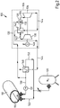
- the in the Fig. 1 shown plant 10 is used for the interior cleaning of a fluid tank 12, for example, mounted on a substructure in a tanker truck or integrated into a railway tank car.
- the fluid tank 12 has a connection 14 for the supply of fluid into the interior 16. Through a connection 18 of the fluid tank 12, it is possible to remove fluid from the interior 16.
- a nitrogen-filled pressure vessel 20 In the plant 10 there is a nitrogen-filled pressure vessel 20.
- the pressure vessel 20 can be connected to the fluid tank 12 via a connection 22 via the connection 14. From the pressure vessel 20 may in the fluid tank 12 through the conduit 22 in this manner as a primary fluid nitrogen gas are supplied to flush the interior 24 of the fluid tank 12 therewith.
- the nitrogen gas from the pressure vessel 20 in the plant 10 serves as a primary fluid for the fluid tank 12.
- a conveying unit configured as a pump or a compressor be provided, which is arranged in the line 22 between the pressure vessel 20 and the heat exchanger 48 or between the heat exchanger 48 and the fluid tank 12.
- the system 10 includes a micro gas turbine formed turbine system 26 with a burner 28. Via a line 30, which can be connected to the terminal 18 of the fluid tank 12, it is possible, the burner 28 in the turbine system 26 with fluid residues or polluted nitrogen gas as to supply a secondary fluid from the fluid tank 12.
- the plant 10 preferably, but not necessarily, includes a suction conveyor unit 31 designed as a compressor or pump.
- the burner 28 has a combustion chamber 32, in which the nitrogen gas charged with fluid residues or contaminants from the fluid tank 12 is burned with a fuel gas supplied from the outside and with combustion air.
- the burner 28 is for this purpose preferably designed as a so-called two-stage burner, which has a pilot stage as a first burner stage, in which the fuel gas is supplied, and as a second burner stage has a main stage, in which introduced the pressurized with fluid residues or contaminants nitrogen gas is to burn it there in a burner flame generated by the pilot stage.
- the burner 28 is for burning fluid residue or contaminants from the fluid tank 12 can also be a burner which burns nitrogen gas charged with fluid residues or contaminants without supplying additional fuel gas. In this case, however, it must be ensured that the fluid residues and contaminants in the nitrogen gas from the fluid tank 12 have combustion characteristics at least approximately corresponding to the combustion characteristics of fuel gas.
- the burner 28 thereby generates a hot gas jet, which is conducted via a hot gas duct 34 to a gas turbine 36.
- a gas turbine 36 the thermal energy of the hot gas generated by the burner 28 is converted into kinetic energy, which is then transferred to a compressor 38 motion-coupled to the gas turbine and an electric generator 40.
- the compressor is for compressing intake air which is supplied to the burner 28 through an intake air passage 42.
- electrical energy can be provided for a not further illustrated line network with electrical consumers.
- the exhaust gas of the gas turbine 36 is guided through an exhaust passage 44.
- the turbine system 26 includes a heat exchanger 46 that transfers heat from the exhaust gas of the gas turbine 36 to the compressed combustion air supplied to the burner 28.
- the exhaust passage 42 of the turbine system 26 is connected to a heat exchanger 48.
- the heat exchanger 48 is for conditioning nitrogen gas from the pressure vessel 20, which is supplied through the conduit 22 to the fluid tank 12 for purging from the interior thereof.
- the heat exchanger 48 is designed for heating nitrogen gas supplied from the pressure vessel 20. By means of the heat exchanger 48, it is possible to heat the nitrogen gas from the pressure vessel 20 from the ambient temperature up to 600 ° C.
- a fluid tank 12 having a large internal volume such as rail tank cars, tank trucks, and ships fluid tanks has interior volumes of up to 700m 3 are not uncommon, can be rinsed.
- the conditioning of the introduced into a fluid tank 12 primary fluid thereby not only causes dissolved in the interior of a fluid tank 12 contaminants, but also that in a fluid tank 12 recorded residual fluid swirled not only with the primary fluid, but by the heat transfer mostly in one gaseous state of aggregation can be transferred.
- Burner 28 thus acts as a means for chemically reacting secondary fluid in the form of primary fluid and residual fluid and contaminants from fluid tank 12 to release heat.
- the structure of the plant 100 in Fig. 2 corresponds basically to the structure of the system 10 Fig. 1 , Assemblies of the plant 100 in Fig. 2 , which are to assemblies in the Appendix 10 from in Fig. 1 are identical in the Fig. 2 in terms of the Fig. 1 numbers increased by the number 100 as reference numerals.
- a conduit section 150 which connects the secondary fluid discharge line 130 from the fluid tank 112 to the primary fluid supply line 122 in the fluid tank 112.
- the primary fluid can be partially circulated through the fluid tank 112, so that it passes through it several times.
- the Saug bankiki 131 instead of the Saug bankong 131 or additionally be provided for this in the line 122 designed as a pump or compressor stage pressure conveying unit.
- the hot exhaust gas of the turbine system 26, 126 in the systems 10, 100 can also be used to heat the fluid tank 12, 112 to be cleaned from the outside.
- the invention relates to a method for interior cleaning of a connection 14, 18 for the supply of fluid and a connection 14, 18 for the removal of fluid having fluid tank 12, 112, in which through the connection 14, 18 for the Feeding fluid into the fluid tank 12, 112 primary fluid is introduced.
- the port (14, 18) for discharging fluid from the fluid tank 12, 112 secondary fluid in the form of fluid contained in the fluid tank 12, 112 and / or primary fluid loaded with such fluid residue or contaminant is used as a secondary fluid dissipated.
- the primary fluid supplied to the fluid tank 12, 112 is heated to a process temperature which is favorable for the internal cleaning of the fluid tank 12, 112.
Landscapes
- Engineering & Computer Science (AREA)
- Mechanical Engineering (AREA)
- Cleaning In General (AREA)
Claims (11)
- Procédé pour le nettoyage intérieur d'un réservoir de fluide (12, 112) présentant un raccord (14, 18) pour l'arrivée de fluide et un raccord (14, 18) pour l'évacuation de fluide,
dans lequel on introduit un fluide primaire inerte dans le réservoir de fluide (12, 112) par le raccord (14, 18) pour l'arrivée de fluide; et
dans lequel on évacue par le raccord (14, 18) pour l'évacuation de fluide hors du réservoir de fluide (12, 112) un fluide secondaire sous la forme des restes de fluide combustibles contenus dans le réservoir de fluide (12, 112) et/ou du fluide primaire chargé de ces restes de fluide ou de polluants, dans lequel
on chauffe à une température de traitement le fluide primaire envoyé au réservoir de fluide (12, 112) pour le nettoyage intérieur du réservoir de fluide (12, 112) par rinçage, et dans lequel
on envoie le fluide secondaire évacué hors du réservoir de fluide (12, 112) au moins en partie à un brûleur (28, 128) pour la conversion chimique du fluide secondaire avec dégagement de chaleur par combustion,
caractérisé en ce que le brûleur (28) produit un courant de gaz chaud, avec lequel on alimente une turbine à gaz (36, 136) pour la production d'énergie cinétique, laquelle est cinétiquement couplée à un consommateur mécanique d'énergie (38, 40, 138, 140), dans lequel la turbine à gaz (36, 136) produit un courant de gaz d'échappement transportant de la chaleur résiduelle, qui est transférée au moins en partie dans un échangeur de chaleur (48, 148) au fluide primaire envoyé au réservoir de fluide (12, 112). - Procédé selon la revendication 1, caractérisé en ce que le consommateur mécanique d'énergie est un compresseur (38, 138) pour la compression de l'air de combustion fourni au brûleur (28, 128), dans lequel de la chaleur perdue est transférée du courant de gaz d'échappement à l'air de combustion comprimé au moyen du compresseur (38, 138).
- Procédé selon une des revendications 1 ou 2, caractérisé en ce que le consommateur mécanique d'énergie est un générateur électrique (40, 140), avec lequel on produit du courant électrique.
- Procédé selon l'une quelconque des revendications 1 à 3, caractérisé en ce que l'on chauffe le réservoir de fluide (12, 112) par l'extérieur au moyen de la chaleur dégagée lors de la conversion chimique du fluide secondaire.
- Installation pour le nettoyage intérieur d'un réservoir de fluide (12, 112) présentant un raccord (14, 18) pour l'arrivée de fluide et un raccord (14, 18, 114, 118) pour l'évacuation de fluide,
avec une conduite (30, 130) pour l'introduction d'un fluide primaire inerte dans le réservoir de fluide (12, 112) pouvant être raccordée au raccord (14, 18, 114, 118) pour l'arrivée de fluide; et
avec une conduite (30, 130) pour l'évacuation d'un fluide secondaire sous la forme de restes de fluide combustibles contenus dans le réservoir de fluide (12, 112) et/ou de fluide primaire chargé de ces restes de fluide ou de polluants, pouvant être raccordée au raccord (14, 18, 114, 118), et
avec un dispositif de conditionnement (48, 148) pour le chauffage du fluide primaire envoyé au réservoir de fluide (12, 112) à une température de traitement pour le nettoyage intérieur du réservoir de fluide (12, 112) par rinçage,
caractérisée par un système de turbine (26, 126), qui présente une turbine à gaz (36, 136) et qui contient un brûleur (28, 128) raccordé à la conduite (30, 130) pour l'évacuation de fluide secondaire pour la production d'un courant de gaz chauds alimentant la turbine à gaz, dans laquelle le système de turbine (26, 126) comporte un canal de gaz d'échappement (44, 144) recevant les gaz d'échappement de la turbine à gaz (36, 136), qui est raccordé à un échangeur de chaleur (48, 148) pour le transfert de chaleur résiduelle des gaz d'échappement de la turbine à gaz (36, 136) au fluide primaire conduit dans la conduite (22, 122) pour l'introduction de fluide primaire dans le réservoir de fluide (12, 112). - Installation selon la revendication 5, caractérisée par un échangeur de chaleur (46, 146) pour le transfert de chaleur des gaz d'échappement de la turbine à gaz (36, 136) à un air de combustion fourni au brûleur (28, 128).
- Installation selon la revendication 5 ou 6, caractérisée en ce que la turbine à gaz (36, 136) est cinétiquement couplée à un compresseur (38, 138) pour la compression de l'air de combustion fourni au brûleur (28, 128).
- Installation selon l'une quelconque des revendications 5 à 7, caractérisée en ce que la turbine à gaz (36, 136) est cinétiquement couplée à un générateur électrique (40, 140) pour la production de courant électrique.
- Installation selon l'une quelconque des revendications 5 à 8, caractérisée par une partie de conduite (150), qui relie la conduite (130) pour l'évacuation de fluide secondaire hors du réservoir de fluide (112) à la conduite (130) pour l'introduction de fluide primaire dans le réservoir de fluide (112), afin de fournir de nouveau au réservoir de fluide (112) le fluide secondaire évacué hors du réservoir de fluide (112).
- Installation selon l'une quelconque des revendications 5 à 8, caractérisée par une partie de conduite (150), qui relie la conduite (130) pour l'évacuation de fluide secondaire hors du réservoir de fluide (112) à la conduite (130) pour l'introduction de fluide primaire dans le réservoir de fluide (112), afin de fournir de nouveau au réservoir de fluide (112) le fluide secondaire évacué hors du réservoir de fluide (112), dans laquelle un échangeur de chaleur (148) est disposé dans la partie de conduite (150) pour le transfert de chaleur perdue des gaz d'échappement de la turbine à gaz (136) au fluide primaire introduit de nouveau dans le réservoir de fluide (112).
- Utilisation d'un système de turbine (26, 126) pour le nettoyage intérieur d'un réservoir de fluide (12, 112) avec un fluide primaire inerte,
dans laquelle le système de turbine (26, 126) comprend un brûleur (28, 128) et une turbine à gaz (36, 136) couplée à un compresseur (38, 138),
dans laquelle le brûleur (28, 128) est alimenté avec un fluide secondaire, qui se compose de restes de fluide combustibles contenus dans le réservoir de fluide (12, 112) et/ou de fluide primaire chargé de ces restes de fluide ou de polluants, et
dans laquelle les gaz d'échappement dégagés par le système de turbine (26, 126) sont envoyés à un échangeur de chaleur (48, 148) pour le chauffage du fluide primaire à une température de traitement pour le nettoyage intérieur du réservoir de fluide (112) par rinçage.
Applications Claiming Priority (1)
| Application Number | Priority Date | Filing Date | Title |
|---|---|---|---|
| DE102013206908.1A DE102013206908A1 (de) | 2013-04-17 | 2013-04-17 | Verfahren und Vorrichtung zum Innenreinigen eines Fluidtanks |
Publications (2)
| Publication Number | Publication Date |
|---|---|
| EP2792425A1 EP2792425A1 (fr) | 2014-10-22 |
| EP2792425B1 true EP2792425B1 (fr) | 2017-05-31 |
Family
ID=50424073
Family Applications (1)
| Application Number | Title | Priority Date | Filing Date |
|---|---|---|---|
| EP14163059.0A Not-in-force EP2792425B1 (fr) | 2013-04-17 | 2014-04-01 | Procédé, dispositif et utilisation d'un système de turbine pour le nettoyage intérieur d'un réservoir de fluide |
Country Status (2)
| Country | Link |
|---|---|
| EP (1) | EP2792425B1 (fr) |
| DE (1) | DE102013206908A1 (fr) |
Family Cites Families (11)
| Publication number | Priority date | Publication date | Assignee | Title |
|---|---|---|---|---|
| DE3213711A1 (de) * | 1982-04-14 | 1983-10-27 | Manfred Dr. 2104 Hamburg Nitsche | Verfahren zur reinigung von behaeltern von brennbaren fluechtigen oder verdampfbaren stoffen |
| AT395951B (de) * | 1991-02-19 | 1993-04-26 | Union Ind Compr Gase Gmbh | Reinigung von werkstuecken mit organischen rueckstaenden |
| US5377723A (en) * | 1993-09-03 | 1995-01-03 | Henry T. Hilliard, Jr. | Method and apparatus for venting a storage vessel |
| DE4423188C2 (de) * | 1994-07-01 | 1999-03-11 | Linde Ag | Reinigung von Druckgasbehältern |
| CA2184285C (fr) * | 1994-12-30 | 1999-04-20 | Einar Brendeng | Procede de vidange d'un reservoir et installation a cet effet |
| TW446800B (en) * | 1998-12-18 | 2001-07-21 | Exxon Production Research Co | Process for unloading pressurized liquefied natural gas from containers |
| DE10247511A1 (de) * | 2002-10-11 | 2004-04-22 | Linde Ag | Verfahren zum Entleeren eines Behälters |
| JP5099326B2 (ja) * | 2007-08-31 | 2012-12-19 | 農工大ティー・エル・オー株式会社 | 揮発性有機化合物の排出、回収、処理方法、タンクコンテナ内の洗浄処理方法及びタンクコンテナ内の洗浄処理装置表示具保持装置 |
| DE102009002455A1 (de) * | 2009-04-17 | 2010-10-21 | Endegs Gmbh | Verfahren und System zur Entfernung von Flüssigkeiten und/oder Gasen |
| DE102011003972A1 (de) * | 2011-02-11 | 2012-08-16 | Endegs Gmbh | System und Verfahren zum Entgasen einer Lager- und/oder Transporteinrichtung für Feststoffe, Flüssigkeiten und/oder Gase |
| DE102011001374B4 (de) * | 2011-03-17 | 2013-06-06 | Deutsches Zentrum für Luft- und Raumfahrt e.V. | Verfahren und Vorrichtung zur Reinigung eines schadstoffhaltigen Fluids |
-
2013
- 2013-04-17 DE DE102013206908.1A patent/DE102013206908A1/de not_active Withdrawn
-
2014
- 2014-04-01 EP EP14163059.0A patent/EP2792425B1/fr not_active Not-in-force
Also Published As
| Publication number | Publication date |
|---|---|
| EP2792425A1 (fr) | 2014-10-22 |
| DE102013206908A1 (de) | 2014-10-23 |
Similar Documents
| Publication | Publication Date | Title |
|---|---|---|
| JP5100318B2 (ja) | 低引火点燃料の貯蔵システム | |
| DE2222162A1 (de) | Verfahren und Einrichtung zur Wasserstofferzeugung fuer einen Gasmotor | |
| WO2003062698A1 (fr) | Procede pour evacuer des gaz d'evaporation d'un reservoir cryogenique, et vehicule dans lequel ce procede intervient | |
| EP3129699B1 (fr) | Système de drainage et de remplissage de carburant cryogénique dans un réservoir de véhicule | |
| EP3625099B1 (fr) | Véhicule ferroviaire avec stockage d'énergie | |
| EP1137895A1 (fr) | Procede et dispositif permettant de transformer les gaz s'echappant par evaporation des cryo-reservoirs | |
| EP2241806B1 (fr) | Procédé et système d'élimination de liquides et/ou de gaz | |
| EP2792425B1 (fr) | Procédé, dispositif et utilisation d'un système de turbine pour le nettoyage intérieur d'un réservoir de fluide | |
| EP0297432B1 (fr) | Procédé pour faire fonctionner une installation de pyrolyse | |
| EP2971962B1 (fr) | Systeme et procede de traitement d'un résidu d'huile lourde | |
| EP2835582B1 (fr) | Installation transportable et procédé destiné à la combustion de gaz indésirables | |
| EP2700875B1 (fr) | Procédé pour le traitement thermique de matériaux de démolition routiers contenant du PAK ou de boues pétrolières | |
| DE102011003972A1 (de) | System und Verfahren zum Entgasen einer Lager- und/oder Transporteinrichtung für Feststoffe, Flüssigkeiten und/oder Gase | |
| EP2811229B1 (fr) | Installation transportable destinée à la combustion de gaz indésirables | |
| DE102008038051A1 (de) | Verfahren und Betrieb einer Biogasanlage beim Ausfall eines fest installierten Biogasverbrauchers sowie Biogasanlage und Biogas-Notfallheizvorrichtung | |
| DE2540082C3 (de) | Anlage zum Abzug und zur Beseitigung von brennbaren Dämpfen | |
| DE19606181C2 (de) | Verfahren zur energetischen Verwertung von heizwertenthaltenden Gas- oder Dampfgemischen | |
| AT519848B1 (de) | Brennstoffzellensystem für einen SOEC-Betriebszustand | |
| DE102022109097A1 (de) | Verfahren und Vorrichtung zur Versorgung von Verbrauchern mit Wasserstoff | |
| EP3256269B1 (fr) | Procédé pour nettoyer une citerne pour liquide inflammable et dispositif pour réaliser ce nettoyage | |
| DE202013005411U1 (de) | System von Wasser-Elektrolyse-Vorrichtung und Wasserstoff-Verbrennungsofen zur kohlendioxidfreien Energieerzeugung | |
| JP4685644B2 (ja) | 重質油改質装置、重質油改質装置の停止方法及び重質油改質装置を備えたガスタービン | |
| EP0033319B1 (fr) | Procede et installation pour bruler les huiles usees | |
| WO1990012252A1 (fr) | Installation d'aerage pour l'evacuation d'un courant d'air a debit massique et volumetrique eleves | |
| DE2407706A1 (de) | Tanksystem fuer gasbetriebene waermekraftmaschinen, insbesondere kraftfahrzeuge |
Legal Events
| Date | Code | Title | Description |
|---|---|---|---|
| PUAI | Public reference made under article 153(3) epc to a published international application that has entered the european phase |
Free format text: ORIGINAL CODE: 0009012 |
|
| 17P | Request for examination filed |
Effective date: 20140401 |
|
| AK | Designated contracting states |
Kind code of ref document: A1 Designated state(s): AL AT BE BG CH CY CZ DE DK EE ES FI FR GB GR HR HU IE IS IT LI LT LU LV MC MK MT NL NO PL PT RO RS SE SI SK SM TR |
|
| AX | Request for extension of the european patent |
Extension state: BA ME |
|
| R17P | Request for examination filed (corrected) |
Effective date: 20141213 |
|
| RBV | Designated contracting states (corrected) |
Designated state(s): AL AT BE BG CH CY CZ DE DK EE ES FI FR GB GR HR HU IE IS IT LI LT LU LV MC MK MT NL NO PL PT RO RS SE SI SK SM TR |
|
| RAP1 | Party data changed (applicant data changed or rights of an application transferred) |
Owner name: DUERR SYSTEMS AG |
|
| GRAP | Despatch of communication of intention to grant a patent |
Free format text: ORIGINAL CODE: EPIDOSNIGR1 |
|
| INTG | Intention to grant announced |
Effective date: 20170105 |
|
| GRAS | Grant fee paid |
Free format text: ORIGINAL CODE: EPIDOSNIGR3 |
|
| GRAA | (expected) grant |
Free format text: ORIGINAL CODE: 0009210 |
|
| AK | Designated contracting states |
Kind code of ref document: B1 Designated state(s): AL AT BE BG CH CY CZ DE DK EE ES FI FR GB GR HR HU IE IS IT LI LT LU LV MC MK MT NL NO PL PT RO RS SE SI SK SM TR |
|
| REG | Reference to a national code |
Ref country code: CH Ref legal event code: EP Ref country code: GB Ref legal event code: FG4D Free format text: NOT ENGLISH |
|
| REG | Reference to a national code |
Ref country code: AT Ref legal event code: REF Ref document number: 896971 Country of ref document: AT Kind code of ref document: T Effective date: 20170615 |
|
| REG | Reference to a national code |
Ref country code: IE Ref legal event code: FG4D Free format text: LANGUAGE OF EP DOCUMENT: GERMAN |
|
| REG | Reference to a national code |
Ref country code: DE Ref legal event code: R096 Ref document number: 502014003973 Country of ref document: DE |
|
| REG | Reference to a national code |
Ref country code: NL Ref legal event code: FP |
|
| REG | Reference to a national code |
Ref country code: LT Ref legal event code: MG4D |
|
| PG25 | Lapsed in a contracting state [announced via postgrant information from national office to epo] |
Ref country code: NO Free format text: LAPSE BECAUSE OF FAILURE TO SUBMIT A TRANSLATION OF THE DESCRIPTION OR TO PAY THE FEE WITHIN THE PRESCRIBED TIME-LIMIT Effective date: 20170831 Ref country code: FI Free format text: LAPSE BECAUSE OF FAILURE TO SUBMIT A TRANSLATION OF THE DESCRIPTION OR TO PAY THE FEE WITHIN THE PRESCRIBED TIME-LIMIT Effective date: 20170531 Ref country code: ES Free format text: LAPSE BECAUSE OF FAILURE TO SUBMIT A TRANSLATION OF THE DESCRIPTION OR TO PAY THE FEE WITHIN THE PRESCRIBED TIME-LIMIT Effective date: 20170531 Ref country code: GR Free format text: LAPSE BECAUSE OF FAILURE TO SUBMIT A TRANSLATION OF THE DESCRIPTION OR TO PAY THE FEE WITHIN THE PRESCRIBED TIME-LIMIT Effective date: 20170901 Ref country code: LT Free format text: LAPSE BECAUSE OF FAILURE TO SUBMIT A TRANSLATION OF THE DESCRIPTION OR TO PAY THE FEE WITHIN THE PRESCRIBED TIME-LIMIT Effective date: 20170531 Ref country code: HR Free format text: LAPSE BECAUSE OF FAILURE TO SUBMIT A TRANSLATION OF THE DESCRIPTION OR TO PAY THE FEE WITHIN THE PRESCRIBED TIME-LIMIT Effective date: 20170531 |
|
| PG25 | Lapsed in a contracting state [announced via postgrant information from national office to epo] |
Ref country code: LV Free format text: LAPSE BECAUSE OF FAILURE TO SUBMIT A TRANSLATION OF THE DESCRIPTION OR TO PAY THE FEE WITHIN THE PRESCRIBED TIME-LIMIT Effective date: 20170531 Ref country code: RS Free format text: LAPSE BECAUSE OF FAILURE TO SUBMIT A TRANSLATION OF THE DESCRIPTION OR TO PAY THE FEE WITHIN THE PRESCRIBED TIME-LIMIT Effective date: 20170531 Ref country code: BG Free format text: LAPSE BECAUSE OF FAILURE TO SUBMIT A TRANSLATION OF THE DESCRIPTION OR TO PAY THE FEE WITHIN THE PRESCRIBED TIME-LIMIT Effective date: 20170831 Ref country code: IS Free format text: LAPSE BECAUSE OF FAILURE TO SUBMIT A TRANSLATION OF THE DESCRIPTION OR TO PAY THE FEE WITHIN THE PRESCRIBED TIME-LIMIT Effective date: 20170930 Ref country code: SE Free format text: LAPSE BECAUSE OF FAILURE TO SUBMIT A TRANSLATION OF THE DESCRIPTION OR TO PAY THE FEE WITHIN THE PRESCRIBED TIME-LIMIT Effective date: 20170531 |
|
| PG25 | Lapsed in a contracting state [announced via postgrant information from national office to epo] |
Ref country code: SK Free format text: LAPSE BECAUSE OF FAILURE TO SUBMIT A TRANSLATION OF THE DESCRIPTION OR TO PAY THE FEE WITHIN THE PRESCRIBED TIME-LIMIT Effective date: 20170531 Ref country code: EE Free format text: LAPSE BECAUSE OF FAILURE TO SUBMIT A TRANSLATION OF THE DESCRIPTION OR TO PAY THE FEE WITHIN THE PRESCRIBED TIME-LIMIT Effective date: 20170531 Ref country code: DK Free format text: LAPSE BECAUSE OF FAILURE TO SUBMIT A TRANSLATION OF THE DESCRIPTION OR TO PAY THE FEE WITHIN THE PRESCRIBED TIME-LIMIT Effective date: 20170531 Ref country code: CZ Free format text: LAPSE BECAUSE OF FAILURE TO SUBMIT A TRANSLATION OF THE DESCRIPTION OR TO PAY THE FEE WITHIN THE PRESCRIBED TIME-LIMIT Effective date: 20170531 Ref country code: RO Free format text: LAPSE BECAUSE OF FAILURE TO SUBMIT A TRANSLATION OF THE DESCRIPTION OR TO PAY THE FEE WITHIN THE PRESCRIBED TIME-LIMIT Effective date: 20170531 |
|
| PG25 | Lapsed in a contracting state [announced via postgrant information from national office to epo] |
Ref country code: PL Free format text: LAPSE BECAUSE OF FAILURE TO SUBMIT A TRANSLATION OF THE DESCRIPTION OR TO PAY THE FEE WITHIN THE PRESCRIBED TIME-LIMIT Effective date: 20170531 Ref country code: IT Free format text: LAPSE BECAUSE OF FAILURE TO SUBMIT A TRANSLATION OF THE DESCRIPTION OR TO PAY THE FEE WITHIN THE PRESCRIBED TIME-LIMIT Effective date: 20170531 Ref country code: SM Free format text: LAPSE BECAUSE OF FAILURE TO SUBMIT A TRANSLATION OF THE DESCRIPTION OR TO PAY THE FEE WITHIN THE PRESCRIBED TIME-LIMIT Effective date: 20170531 |
|
| REG | Reference to a national code |
Ref country code: DE Ref legal event code: R097 Ref document number: 502014003973 Country of ref document: DE |
|
| PLBE | No opposition filed within time limit |
Free format text: ORIGINAL CODE: 0009261 |
|
| STAA | Information on the status of an ep patent application or granted ep patent |
Free format text: STATUS: NO OPPOSITION FILED WITHIN TIME LIMIT |
|
| REG | Reference to a national code |
Ref country code: FR Ref legal event code: PLFP Year of fee payment: 5 |
|
| 26N | No opposition filed |
Effective date: 20180301 |
|
| PG25 | Lapsed in a contracting state [announced via postgrant information from national office to epo] |
Ref country code: SI Free format text: LAPSE BECAUSE OF FAILURE TO SUBMIT A TRANSLATION OF THE DESCRIPTION OR TO PAY THE FEE WITHIN THE PRESCRIBED TIME-LIMIT Effective date: 20170531 |
|
| PG25 | Lapsed in a contracting state [announced via postgrant information from national office to epo] |
Ref country code: MT Free format text: LAPSE BECAUSE OF FAILURE TO SUBMIT A TRANSLATION OF THE DESCRIPTION OR TO PAY THE FEE WITHIN THE PRESCRIBED TIME-LIMIT Effective date: 20170531 |
|
| PG25 | Lapsed in a contracting state [announced via postgrant information from national office to epo] |
Ref country code: MC Free format text: LAPSE BECAUSE OF FAILURE TO SUBMIT A TRANSLATION OF THE DESCRIPTION OR TO PAY THE FEE WITHIN THE PRESCRIBED TIME-LIMIT Effective date: 20170531 |
|
| PG25 | Lapsed in a contracting state [announced via postgrant information from national office to epo] |
Ref country code: LU Free format text: LAPSE BECAUSE OF NON-PAYMENT OF DUE FEES Effective date: 20180401 |
|
| PG25 | Lapsed in a contracting state [announced via postgrant information from national office to epo] |
Ref country code: TR Free format text: LAPSE BECAUSE OF FAILURE TO SUBMIT A TRANSLATION OF THE DESCRIPTION OR TO PAY THE FEE WITHIN THE PRESCRIBED TIME-LIMIT Effective date: 20170531 |
|
| PG25 | Lapsed in a contracting state [announced via postgrant information from national office to epo] |
Ref country code: PT Free format text: LAPSE BECAUSE OF FAILURE TO SUBMIT A TRANSLATION OF THE DESCRIPTION OR TO PAY THE FEE WITHIN THE PRESCRIBED TIME-LIMIT Effective date: 20170531 Ref country code: HU Free format text: LAPSE BECAUSE OF FAILURE TO SUBMIT A TRANSLATION OF THE DESCRIPTION OR TO PAY THE FEE WITHIN THE PRESCRIBED TIME-LIMIT; INVALID AB INITIO Effective date: 20140401 |
|
| PG25 | Lapsed in a contracting state [announced via postgrant information from national office to epo] |
Ref country code: MK Free format text: LAPSE BECAUSE OF NON-PAYMENT OF DUE FEES Effective date: 20170531 Ref country code: CY Free format text: LAPSE BECAUSE OF FAILURE TO SUBMIT A TRANSLATION OF THE DESCRIPTION OR TO PAY THE FEE WITHIN THE PRESCRIBED TIME-LIMIT Effective date: 20170531 |
|
| PG25 | Lapsed in a contracting state [announced via postgrant information from national office to epo] |
Ref country code: AL Free format text: LAPSE BECAUSE OF FAILURE TO SUBMIT A TRANSLATION OF THE DESCRIPTION OR TO PAY THE FEE WITHIN THE PRESCRIBED TIME-LIMIT Effective date: 20170531 |
|
| PGFP | Annual fee paid to national office [announced via postgrant information from national office to epo] |
Ref country code: DE Payment date: 20210420 Year of fee payment: 8 Ref country code: FR Payment date: 20210423 Year of fee payment: 8 |
|
| PGFP | Annual fee paid to national office [announced via postgrant information from national office to epo] |
Ref country code: IE Payment date: 20210428 Year of fee payment: 8 Ref country code: BE Payment date: 20210420 Year of fee payment: 8 Ref country code: AT Payment date: 20210421 Year of fee payment: 8 Ref country code: CH Payment date: 20210420 Year of fee payment: 8 Ref country code: GB Payment date: 20210422 Year of fee payment: 8 |
|
| PGFP | Annual fee paid to national office [announced via postgrant information from national office to epo] |
Ref country code: NL Payment date: 20210420 Year of fee payment: 8 |
|
| REG | Reference to a national code |
Ref country code: DE Ref legal event code: R119 Ref document number: 502014003973 Country of ref document: DE |
|
| REG | Reference to a national code |
Ref country code: CH Ref legal event code: PL |
|
| REG | Reference to a national code |
Ref country code: NL Ref legal event code: MM Effective date: 20220501 |
|
| REG | Reference to a national code |
Ref country code: AT Ref legal event code: MM01 Ref document number: 896971 Country of ref document: AT Kind code of ref document: T Effective date: 20220401 |
|
| GBPC | Gb: european patent ceased through non-payment of renewal fee |
Effective date: 20220401 |
|
| REG | Reference to a national code |
Ref country code: BE Ref legal event code: MM Effective date: 20220430 |
|
| PG25 | Lapsed in a contracting state [announced via postgrant information from national office to epo] |
Ref country code: NL Free format text: LAPSE BECAUSE OF NON-PAYMENT OF DUE FEES Effective date: 20220501 Ref country code: LI Free format text: LAPSE BECAUSE OF NON-PAYMENT OF DUE FEES Effective date: 20220430 Ref country code: GB Free format text: LAPSE BECAUSE OF NON-PAYMENT OF DUE FEES Effective date: 20220401 Ref country code: FR Free format text: LAPSE BECAUSE OF NON-PAYMENT OF DUE FEES Effective date: 20220430 Ref country code: DE Free format text: LAPSE BECAUSE OF NON-PAYMENT OF DUE FEES Effective date: 20221103 Ref country code: CH Free format text: LAPSE BECAUSE OF NON-PAYMENT OF DUE FEES Effective date: 20220430 Ref country code: AT Free format text: LAPSE BECAUSE OF NON-PAYMENT OF DUE FEES Effective date: 20220401 |
|
| PG25 | Lapsed in a contracting state [announced via postgrant information from national office to epo] |
Ref country code: BE Free format text: LAPSE BECAUSE OF NON-PAYMENT OF DUE FEES Effective date: 20220430 |
|
| PG25 | Lapsed in a contracting state [announced via postgrant information from national office to epo] |
Ref country code: IE Free format text: LAPSE BECAUSE OF NON-PAYMENT OF DUE FEES Effective date: 20220401 |