EP2794227B1 - Buse d'extrusion et procédé destinée à produire une bande profilée variable en continu - Google Patents
Buse d'extrusion et procédé destinée à produire une bande profilée variable en continu Download PDFInfo
- Publication number
- EP2794227B1 EP2794227B1 EP12783994.2A EP12783994A EP2794227B1 EP 2794227 B1 EP2794227 B1 EP 2794227B1 EP 12783994 A EP12783994 A EP 12783994A EP 2794227 B1 EP2794227 B1 EP 2794227B1
- Authority
- EP
- European Patent Office
- Prior art keywords
- slide
- guide
- extrusion die
- opening
- extrusion
- Prior art date
- Legal status (The legal status is an assumption and is not a legal conclusion. Google has not performed a legal analysis and makes no representation as to the accuracy of the status listed.)
- Not-in-force
Links
- 238000001125 extrusion Methods 0.000 title claims description 78
- 238000004519 manufacturing process Methods 0.000 title description 8
- 229920000642 polymer Polymers 0.000 claims description 21
- 239000011521 glass Substances 0.000 claims description 17
- 238000000034 method Methods 0.000 claims description 10
- 239000000758 substrate Substances 0.000 claims description 9
- 239000000314 lubricant Substances 0.000 claims description 8
- 238000007373 indentation Methods 0.000 claims description 4
- 229910052751 metal Inorganic materials 0.000 claims description 4
- 239000002184 metal Substances 0.000 claims description 4
- 150000002739 metals Chemical class 0.000 claims description 4
- 238000007493 shaping process Methods 0.000 claims description 3
- 229920002379 silicone rubber Polymers 0.000 description 12
- 239000004945 silicone rubber Substances 0.000 description 12
- 229920002943 EPDM rubber Polymers 0.000 description 8
- 229920002725 thermoplastic elastomer Polymers 0.000 description 8
- 229920000459 Nitrile rubber Polymers 0.000 description 7
- 239000000203 mixture Substances 0.000 description 7
- 238000000465 moulding Methods 0.000 description 7
- 229920001971 elastomer Polymers 0.000 description 6
- 229920002635 polyurethane Polymers 0.000 description 6
- 239000004814 polyurethane Substances 0.000 description 6
- 239000005060 rubber Substances 0.000 description 6
- VYZAMTAEIAYCRO-UHFFFAOYSA-N Chromium Chemical compound [Cr] VYZAMTAEIAYCRO-UHFFFAOYSA-N 0.000 description 4
- XEEYBQQBJWHFJM-UHFFFAOYSA-N Iron Chemical compound [Fe] XEEYBQQBJWHFJM-UHFFFAOYSA-N 0.000 description 4
- PXHVJJICTQNCMI-UHFFFAOYSA-N Nickel Chemical compound [Ni] PXHVJJICTQNCMI-UHFFFAOYSA-N 0.000 description 4
- 229910052804 chromium Inorganic materials 0.000 description 4
- 239000011651 chromium Substances 0.000 description 4
- 238000004132 cross linking Methods 0.000 description 4
- 239000004033 plastic Substances 0.000 description 4
- 229920003023 plastic Polymers 0.000 description 4
- 238000007789 sealing Methods 0.000 description 4
- 229920001169 thermoplastic Polymers 0.000 description 4
- 244000043261 Hevea brasiliensis Species 0.000 description 3
- NTXGQCSETZTARF-UHFFFAOYSA-N buta-1,3-diene;prop-2-enenitrile Chemical compound C=CC=C.C=CC#N NTXGQCSETZTARF-UHFFFAOYSA-N 0.000 description 3
- 230000008859 change Effects 0.000 description 3
- 238000006073 displacement reaction Methods 0.000 description 3
- 229920003052 natural elastomer Polymers 0.000 description 3
- 229920001194 natural rubber Polymers 0.000 description 3
- 229920000058 polyacrylate Polymers 0.000 description 3
- 229920000647 polyepoxide Polymers 0.000 description 3
- 229920000098 polyolefin Polymers 0.000 description 3
- 229920001296 polysiloxane Polymers 0.000 description 3
- 229920001021 polysulfide Polymers 0.000 description 3
- 239000005077 polysulfide Substances 0.000 description 3
- 150000008117 polysulfides Polymers 0.000 description 3
- 229920003048 styrene butadiene rubber Polymers 0.000 description 3
- ZOKXTWBITQBERF-UHFFFAOYSA-N Molybdenum Chemical compound [Mo] ZOKXTWBITQBERF-UHFFFAOYSA-N 0.000 description 2
- VYPSYNLAJGMNEJ-UHFFFAOYSA-N Silicium dioxide Chemical compound O=[Si]=O VYPSYNLAJGMNEJ-UHFFFAOYSA-N 0.000 description 2
- RTAQQCXQSZGOHL-UHFFFAOYSA-N Titanium Chemical compound [Ti] RTAQQCXQSZGOHL-UHFFFAOYSA-N 0.000 description 2
- 150000001336 alkenes Chemical class 0.000 description 2
- 239000000956 alloy Substances 0.000 description 2
- 229910045601 alloy Inorganic materials 0.000 description 2
- 229910052782 aluminium Inorganic materials 0.000 description 2
- XAGFODPZIPBFFR-UHFFFAOYSA-N aluminium Chemical compound [Al] XAGFODPZIPBFFR-UHFFFAOYSA-N 0.000 description 2
- 238000004873 anchoring Methods 0.000 description 2
- 230000015572 biosynthetic process Effects 0.000 description 2
- 229920001400 block copolymer Polymers 0.000 description 2
- 239000005388 borosilicate glass Substances 0.000 description 2
- MTAZNLWOLGHBHU-UHFFFAOYSA-N butadiene-styrene rubber Chemical compound C=CC=C.C=CC1=CC=CC=C1 MTAZNLWOLGHBHU-UHFFFAOYSA-N 0.000 description 2
- 229910017052 cobalt Inorganic materials 0.000 description 2
- 239000010941 cobalt Substances 0.000 description 2
- GUTLYIVDDKVIGB-UHFFFAOYSA-N cobalt atom Chemical compound [Co] GUTLYIVDDKVIGB-UHFFFAOYSA-N 0.000 description 2
- 238000001816 cooling Methods 0.000 description 2
- 239000005357 flat glass Substances 0.000 description 2
- 239000005329 float glass Substances 0.000 description 2
- 239000012530 fluid Substances 0.000 description 2
- 229910052500 inorganic mineral Inorganic materials 0.000 description 2
- 238000009434 installation Methods 0.000 description 2
- 229910052742 iron Inorganic materials 0.000 description 2
- WPBNNNQJVZRUHP-UHFFFAOYSA-L manganese(2+);methyl n-[[2-(methoxycarbonylcarbamothioylamino)phenyl]carbamothioyl]carbamate;n-[2-(sulfidocarbothioylamino)ethyl]carbamodithioate Chemical compound [Mn+2].[S-]C(=S)NCCNC([S-])=S.COC(=O)NC(=S)NC1=CC=CC=C1NC(=S)NC(=O)OC WPBNNNQJVZRUHP-UHFFFAOYSA-L 0.000 description 2
- 239000011707 mineral Substances 0.000 description 2
- 238000002156 mixing Methods 0.000 description 2
- 229910052750 molybdenum Inorganic materials 0.000 description 2
- 239000011733 molybdenum Substances 0.000 description 2
- 229910052759 nickel Inorganic materials 0.000 description 2
- 229910052758 niobium Inorganic materials 0.000 description 2
- 239000010955 niobium Substances 0.000 description 2
- GUCVJGMIXFAOAE-UHFFFAOYSA-N niobium atom Chemical compound [Nb] GUCVJGMIXFAOAE-UHFFFAOYSA-N 0.000 description 2
- JRZJOMJEPLMPRA-UHFFFAOYSA-N olefin Natural products CCCCCCCC=C JRZJOMJEPLMPRA-UHFFFAOYSA-N 0.000 description 2
- 229920003229 poly(methyl methacrylate) Polymers 0.000 description 2
- 239000004417 polycarbonate Substances 0.000 description 2
- 229920000515 polycarbonate Polymers 0.000 description 2
- 239000004926 polymethyl methacrylate Substances 0.000 description 2
- 230000009467 reduction Effects 0.000 description 2
- 238000000926 separation method Methods 0.000 description 2
- 229920002545 silicone oil Polymers 0.000 description 2
- 239000005361 soda-lime glass Substances 0.000 description 2
- 239000010936 titanium Substances 0.000 description 2
- 229910052719 titanium Inorganic materials 0.000 description 2
- 230000007704 transition Effects 0.000 description 2
- WFKWXMTUELFFGS-UHFFFAOYSA-N tungsten Chemical compound [W] WFKWXMTUELFFGS-UHFFFAOYSA-N 0.000 description 2
- 229910052721 tungsten Inorganic materials 0.000 description 2
- 239000010937 tungsten Substances 0.000 description 2
- 229910052720 vanadium Inorganic materials 0.000 description 2
- LEONUFNNVUYDNQ-UHFFFAOYSA-N vanadium atom Chemical compound [V] LEONUFNNVUYDNQ-UHFFFAOYSA-N 0.000 description 2
- XLYOFNOQVPJJNP-UHFFFAOYSA-N water Substances O XLYOFNOQVPJJNP-UHFFFAOYSA-N 0.000 description 2
- QVGXLLKOCUKJST-UHFFFAOYSA-N atomic oxygen Chemical compound [O] QVGXLLKOCUKJST-UHFFFAOYSA-N 0.000 description 1
- 238000010276 construction Methods 0.000 description 1
- 238000013461 design Methods 0.000 description 1
- 238000011161 development Methods 0.000 description 1
- 239000013536 elastomeric material Substances 0.000 description 1
- 210000003746 feather Anatomy 0.000 description 1
- 239000004519 grease Substances 0.000 description 1
- 238000010438 heat treatment Methods 0.000 description 1
- 238000003780 insertion Methods 0.000 description 1
- 230000037431 insertion Effects 0.000 description 1
- 238000010550 living polymerization reaction Methods 0.000 description 1
- 230000004048 modification Effects 0.000 description 1
- 238000012986 modification Methods 0.000 description 1
- 229910052760 oxygen Inorganic materials 0.000 description 1
- 239000001301 oxygen Substances 0.000 description 1
- 230000002093 peripheral effect Effects 0.000 description 1
- 150000002978 peroxides Chemical class 0.000 description 1
- 238000006068 polycondensation reaction Methods 0.000 description 1
- 238000006116 polymerization reaction Methods 0.000 description 1
- 238000002360 preparation method Methods 0.000 description 1
- 230000008569 process Effects 0.000 description 1
- 230000001105 regulatory effect Effects 0.000 description 1
- 125000006850 spacer group Chemical group 0.000 description 1
- 239000012815 thermoplastic material Substances 0.000 description 1
Images


Classifications
-
- B—PERFORMING OPERATIONS; TRANSPORTING
- B29—WORKING OF PLASTICS; WORKING OF SUBSTANCES IN A PLASTIC STATE IN GENERAL
- B29C—SHAPING OR JOINING OF PLASTICS; SHAPING OF MATERIAL IN A PLASTIC STATE, NOT OTHERWISE PROVIDED FOR; AFTER-TREATMENT OF THE SHAPED PRODUCTS, e.g. REPAIRING
- B29C48/00—Extrusion moulding, i.e. expressing the moulding material through a die or nozzle which imparts the desired form; Apparatus therefor
- B29C48/25—Component parts, details or accessories; Auxiliary operations
- B29C48/30—Extrusion nozzles or dies
- B29C48/305—Extrusion nozzles or dies having a wide opening, e.g. for forming sheets
- B29C48/31—Extrusion nozzles or dies having a wide opening, e.g. for forming sheets being adjustable, i.e. having adjustable exit sections
- B29C48/313—Extrusion nozzles or dies having a wide opening, e.g. for forming sheets being adjustable, i.e. having adjustable exit sections by positioning the die lips
-
- B—PERFORMING OPERATIONS; TRANSPORTING
- B29—WORKING OF PLASTICS; WORKING OF SUBSTANCES IN A PLASTIC STATE IN GENERAL
- B29C—SHAPING OR JOINING OF PLASTICS; SHAPING OF MATERIAL IN A PLASTIC STATE, NOT OTHERWISE PROVIDED FOR; AFTER-TREATMENT OF THE SHAPED PRODUCTS, e.g. REPAIRING
- B29C48/00—Extrusion moulding, i.e. expressing the moulding material through a die or nozzle which imparts the desired form; Apparatus therefor
- B29C48/03—Extrusion moulding, i.e. expressing the moulding material through a die or nozzle which imparts the desired form; Apparatus therefor characterised by the shape of the extruded material at extrusion
- B29C48/12—Articles with an irregular circumference when viewed in cross-section, e.g. window profiles
-
- B—PERFORMING OPERATIONS; TRANSPORTING
- B29—WORKING OF PLASTICS; WORKING OF SUBSTANCES IN A PLASTIC STATE IN GENERAL
- B29C—SHAPING OR JOINING OF PLASTICS; SHAPING OF MATERIAL IN A PLASTIC STATE, NOT OTHERWISE PROVIDED FOR; AFTER-TREATMENT OF THE SHAPED PRODUCTS, e.g. REPAIRING
- B29C48/00—Extrusion moulding, i.e. expressing the moulding material through a die or nozzle which imparts the desired form; Apparatus therefor
- B29C48/03—Extrusion moulding, i.e. expressing the moulding material through a die or nozzle which imparts the desired form; Apparatus therefor characterised by the shape of the extruded material at extrusion
- B29C48/13—Articles with a cross-section varying in the longitudinal direction, e.g. corrugated pipes
-
- B—PERFORMING OPERATIONS; TRANSPORTING
- B29—WORKING OF PLASTICS; WORKING OF SUBSTANCES IN A PLASTIC STATE IN GENERAL
- B29C—SHAPING OR JOINING OF PLASTICS; SHAPING OF MATERIAL IN A PLASTIC STATE, NOT OTHERWISE PROVIDED FOR; AFTER-TREATMENT OF THE SHAPED PRODUCTS, e.g. REPAIRING
- B29C48/00—Extrusion moulding, i.e. expressing the moulding material through a die or nozzle which imparts the desired form; Apparatus therefor
- B29C48/03—Extrusion moulding, i.e. expressing the moulding material through a die or nozzle which imparts the desired form; Apparatus therefor characterised by the shape of the extruded material at extrusion
- B29C48/131—Curved articles
-
- B—PERFORMING OPERATIONS; TRANSPORTING
- B29—WORKING OF PLASTICS; WORKING OF SUBSTANCES IN A PLASTIC STATE IN GENERAL
- B29C—SHAPING OR JOINING OF PLASTICS; SHAPING OF MATERIAL IN A PLASTIC STATE, NOT OTHERWISE PROVIDED FOR; AFTER-TREATMENT OF THE SHAPED PRODUCTS, e.g. REPAIRING
- B29C48/00—Extrusion moulding, i.e. expressing the moulding material through a die or nozzle which imparts the desired form; Apparatus therefor
- B29C48/15—Extrusion moulding, i.e. expressing the moulding material through a die or nozzle which imparts the desired form; Apparatus therefor incorporating preformed parts or layers, e.g. extrusion moulding around inserts
- B29C48/154—Coating solid articles, i.e. non-hollow articles
- B29C48/155—Partial coating thereof
-
- B—PERFORMING OPERATIONS; TRANSPORTING
- B29—WORKING OF PLASTICS; WORKING OF SUBSTANCES IN A PLASTIC STATE IN GENERAL
- B29C—SHAPING OR JOINING OF PLASTICS; SHAPING OF MATERIAL IN A PLASTIC STATE, NOT OTHERWISE PROVIDED FOR; AFTER-TREATMENT OF THE SHAPED PRODUCTS, e.g. REPAIRING
- B29C48/00—Extrusion moulding, i.e. expressing the moulding material through a die or nozzle which imparts the desired form; Apparatus therefor
- B29C48/25—Component parts, details or accessories; Auxiliary operations
- B29C48/30—Extrusion nozzles or dies
- B29C48/302—Extrusion nozzles or dies being adjustable, i.e. having adjustable exit sections
-
- B—PERFORMING OPERATIONS; TRANSPORTING
- B29—WORKING OF PLASTICS; WORKING OF SUBSTANCES IN A PLASTIC STATE IN GENERAL
- B29C—SHAPING OR JOINING OF PLASTICS; SHAPING OF MATERIAL IN A PLASTIC STATE, NOT OTHERWISE PROVIDED FOR; AFTER-TREATMENT OF THE SHAPED PRODUCTS, e.g. REPAIRING
- B29C48/00—Extrusion moulding, i.e. expressing the moulding material through a die or nozzle which imparts the desired form; Apparatus therefor
- B29C48/25—Component parts, details or accessories; Auxiliary operations
- B29C48/92—Measuring, controlling or regulating
-
- B—PERFORMING OPERATIONS; TRANSPORTING
- B29—WORKING OF PLASTICS; WORKING OF SUBSTANCES IN A PLASTIC STATE IN GENERAL
- B29C—SHAPING OR JOINING OF PLASTICS; SHAPING OF MATERIAL IN A PLASTIC STATE, NOT OTHERWISE PROVIDED FOR; AFTER-TREATMENT OF THE SHAPED PRODUCTS, e.g. REPAIRING
- B29C48/00—Extrusion moulding, i.e. expressing the moulding material through a die or nozzle which imparts the desired form; Apparatus therefor
- B29C48/25—Component parts, details or accessories; Auxiliary operations
- B29C48/94—Lubricating
-
- B—PERFORMING OPERATIONS; TRANSPORTING
- B29—WORKING OF PLASTICS; WORKING OF SUBSTANCES IN A PLASTIC STATE IN GENERAL
- B29C—SHAPING OR JOINING OF PLASTICS; SHAPING OF MATERIAL IN A PLASTIC STATE, NOT OTHERWISE PROVIDED FOR; AFTER-TREATMENT OF THE SHAPED PRODUCTS, e.g. REPAIRING
- B29C2948/00—Indexing scheme relating to extrusion moulding
- B29C2948/92—Measuring, controlling or regulating
- B29C2948/92504—Controlled parameter
- B29C2948/9258—Velocity
- B29C2948/926—Flow or feed rate
-
- B—PERFORMING OPERATIONS; TRANSPORTING
- B29—WORKING OF PLASTICS; WORKING OF SUBSTANCES IN A PLASTIC STATE IN GENERAL
- B29C—SHAPING OR JOINING OF PLASTICS; SHAPING OF MATERIAL IN A PLASTIC STATE, NOT OTHERWISE PROVIDED FOR; AFTER-TREATMENT OF THE SHAPED PRODUCTS, e.g. REPAIRING
- B29C2948/00—Indexing scheme relating to extrusion moulding
- B29C2948/92—Measuring, controlling or regulating
- B29C2948/92504—Controlled parameter
- B29C2948/92609—Dimensions
- B29C2948/92628—Width or height
-
- B—PERFORMING OPERATIONS; TRANSPORTING
- B29—WORKING OF PLASTICS; WORKING OF SUBSTANCES IN A PLASTIC STATE IN GENERAL
- B29C—SHAPING OR JOINING OF PLASTICS; SHAPING OF MATERIAL IN A PLASTIC STATE, NOT OTHERWISE PROVIDED FOR; AFTER-TREATMENT OF THE SHAPED PRODUCTS, e.g. REPAIRING
- B29C2948/00—Indexing scheme relating to extrusion moulding
- B29C2948/92—Measuring, controlling or regulating
- B29C2948/92504—Controlled parameter
- B29C2948/92609—Dimensions
- B29C2948/92647—Thickness
Definitions
- the invention relates to an extrusion nozzle with a regulatable nozzle opening for producing a continuously variable profile strand.
- the manufacture of seals on various vehicle components is very important in the automotive industry. In particular glass sheets must be provided with sealing elements before installation in the designated places of the body.
- Commonly used sealing elements include polymers such as polyurethanes, polyolefins, polysulfides, polyepoxides and rubbers such as natural rubber, styrene-butadiene rubber, butadiene-acrylonitrile rubber, ethylene-propylene-diene rubber (EPDM), silicones such as RTV (room temperature vulcanizing silicone rubber, HTV (high temperature cure) silicone rubber, peroxide cured silicone rubber, and / or addition cured silicone rubber, polyacrylates, and / or thermoplastic elastomers, which serve to manage water and prevent the ingress of moisture, as well as preventing the development of disturbing driving noises such as whistling noises in the passenger compartment.
- polymers such as polyurethanes, polyolefins, polysulfides, polyepoxides and rubbers such as natural rubber, styrene-butadiene rubber, butadiene-acrylonitrile rubber, ethylene-propylene-diene rubber (EPDM
- Another important function is the stress-free, reproducible and stable insertion of the glass elements into the recess provided in the body of the vehicle.
- a polymer composition such as polyurethane
- a primer can be applied in preparation.
- the formation of the profile strand is carried out either at the molecular level, for example by living polymerization, chain polymerization, polycondensation, polyaddition or thermoplastic elastomers by heating and subsequent cooling.
- polymer crosslinking for example by increasing the temperature, atmospheric humidity, or oxygen addition, can also follow.
- DE 196 04 397 C1 discloses a device for extruding a frame-shaped profile strand on a glass pane.
- the extrusion die has an elongated lip gap, which can be covered at the end by a slide.
- DE 42 32 554 C1 discloses a method of making a glass sheet provided with a molded thermoplastic polymer frame and a corresponding device.
- the glass sheet to be processed is placed before the actual extrusion on a heated mold bed, which projects beyond the glass pane edges.
- the produced extruded profile projects beyond the glass pane according to the mold bed.
- DE 39 30 414 A1 discloses a profiled frame glass sheet which is produced by extrusion and curing on the sheet.
- EP 0 407 364 A1 describes a weather strip which is suitable for being placed on the edge of an opening, an extrusion die for producing the weather strip and a method for the production thereof.
- the weather strip comprises an anchoring profile and a tubular sealing profile which is coextruded with the anchoring profile.
- US RE37,737 E describes a windshield molding for motor vehicles, which seals the space between the windshield and the vehicle body. Further, a method and an extrusion die for its production is disclosed.
- US Pat. No. 6,174,477 B1 discloses a window frame trim for a motor vehicle, an apparatus, and a method of manufacturing the window frame trim.
- the method and apparatus provide a window frame strip with high accuracy with improved process productivity.
- EP 0 081 093 A1 discloses an extruder with a shaping Strandpressdüse for producing profiled strands of elastomeric material.
- JP H 10 86206 A a method and an apparatus for producing a window molding for motor vehicles is described.
- JP H 08 197606 A discloses a window molding for motor vehicles with improved water drainage and low manufacturing costs.
- US 5 233 805 A describes a molded part for a front glass for motor vehicles and a molding apparatus for producing the same.
- a molding for fitting in the gap of an automobile body existing between the peripheral edge of an automobile front glass and a window frame will be described.
- DE 697 18 385 T2 relates to a decorative element for a motor vehicle and a method and an apparatus for its production.
- the apparatus comprises an extrusion die assembly having a stationary nozzle, a first movable nozzle and a second movable nozzle, wherein the first movable nozzle and the second movable nozzle are displaceable parallel to one another.
- the width or height of the profile strand as well as the formation of the lip in many cases must be varied in the same component. Repeated changes of the extruded geometry are necessary in many applications. These specified by the workpiece and body changes in the profile strand make a modification of the outlet opening of the extrusion die or even their replacement required. In addition to the surface of the outlet opening, the width of the gap for forming the lip often has to be reproducibly varied at the same time.
- the object of the invention is to provide an extrusion nozzle for the application of a variable profile strand, which allows a simultaneous change in the geometry of both the profile strand and the profile lip.
- the invention discloses an extrusion die for applying a variable profile strand.
- the extrusion die comprises at least one extrusion die body with a die opening and a slider in front of the nozzle opening.
- the nozzle opening includes a main opening for forming the tread strand and a bulge connected to the main opening for forming a lip connected to the tread strand.
- the slider comprises a first partial slide arranged behind one another and connected to one another via a sliding guide and a second partial slide, wherein the first partial slide and the second partial slide are coupled in the movement and wherein the first partial slide is vertically displaceable to reduce the main opening and the second partial slide is horizontally displaceable to reduce the bulge.
- the diameter of the nozzle opening is determined parallel to the surface to be coated.
- the extrusion die body comprises when using a thermoplastic polymer prefers a feed channel for transporting the molten polymer to the nozzle orifice.
- a slide is arranged, which can cover adjustable portions of the nozzle opening and thus can change the shape and geometry of the resulting profile strand.
- the slide comprises at least one first partial slide arranged one behind the other and a second partial slide.
- the first partial slide and the second partial slide are connected to each other via a sliding guide, preferably groove-spring system, particularly preferably form-fitting guide, in particular dovetail, or T-groove.
- the term "spring" in the sense of the invention comprises a device which can be displaced in the notch of the groove.
- the positive guidance on the dovetail connection prevents detachment of the first part of the slide and the second part of each slide.
- the first partial slide and the second partial slide are coupled together in the movement.
- the first partial slide is vertical and the second partial slide horizontally displaceable with respect to the nozzle opening.
- the sliding guide thus enables a simultaneous displacement of the first part of the slide along the central axis of the extrusion die and the second part of the slide orthogonal to the central axis of the extrusion die.
- the first partial slide and the second partial slide allow continuous variation of the shape and geometry of the profile body.
- the first partial slide preferably comprises the spring, the second partial slide the groove.
- the first part of the slide can thus be moved over the example milled spring within the groove of the second part of the slide.
- the sliding guide particularly preferably comprises a lubricant between the spring and the groove, which reduces the frictional forces existing between the groove and spring.
- the nozzle opening comprises a main opening for forming a profile strand (extruded strand) and a bulge connected to the main opening for forming a lip connected to the profile strand.
- the main opening and the bulge preferably merge into each other.
- the bulge preferably comprises 30% to 70% of the maximum diameter in the cross section of the nozzle opening without a slide.
- the first partial slide preferably has a notch in the region of the nozzle opening.
- the notch allows according to the desired application form, a further variation of the profile strand height.
- the second partial slide preferably has a notch in the region of the nozzle opening.
- the indentation allows a further variation of the lip size according to the desired application form.
- the term "in the area of the nozzle opening” defines the portion of the partial slide which can be displaced directly above or adjacent to the nozzle opening and influences the extent of the nozzle opening.
- the extrusion die body preferably comprises a first feed channel and a second feed channel for transporting the molten thermoplastic polymer to the die opening.
- Two feed channels allow for mixing of different polymers in the area in front of or in the nozzle opening.
- the first supply channel and / or second supply channel preferably contain control valves, so that a targeted regulation of the amount of polymer and polymer composition is possible.
- the first partial slide preferably reduces the main opening by at least 50%, particularly preferably by at least 70%.
- the data refer to the maximum displacement to close the main opening of the first part gate valve. The reduction of the main opening allows a targeted variation of the profile string size.
- the second partial slide preferably reduces the bulge by at least 50%, particularly preferably by at least 70%.
- the figures refer to the maximum displacement to close the bulge of the second part of the slide. The reduction of the main opening allows a specific variation of the lip size.
- the extrusion die body and / or partial slide preferably contain metals or thermally stable plastics, preferably iron, chromium, cobalt, nickel, titanium, manganese, aluminum, chromium, niobium, tungsten, molybdenum, vanadium and / or mixtures or alloys thereof.
- the nozzle opening preferably has an area within an imaginary rectangle with the edge lengths 5 mm to 50 mm and 2 mm to 20 mm, preferably within an imaginary rectangle with the edge lengths 10 mm to 30 mm and 5 mm to 15 mm.
- the exact geometry of the nozzle opening is variable and depends on the later form of the extruded profile seal.
- the nozzle opening preferably has a maximum diameter (a) of 0.1 cm to 3 cm, preferably 0.5 cm to 2 cm.
- the nozzle opening preferably has a maximum height in the cross section of 0.1 cm to 3 cm, preferably 0.5 cm to 2 cm.
- the extrusion nozzle according to the invention for the application of a variable profile strand comprises at least one extrusion nozzle body and a nozzle opening in the extrusion nozzle body. Before the nozzle opening a horizontally movable guide slide is arranged.
- the guide slider includes a first guide slide arm having a first guide opening and a second guide slide arm having a second guide opening.
- the extrusion nozzle further comprises in the region of the guide slide arms a first pivot profile element with a protruding first guide cylinder and a second pivot profile element with a protruding second guide cylinder.
- the first guide cylinder is within the first guide opening and the second guide cylinder is movably mounted within the second guide opening.
- the first pivot profile element and the second pivot profile element are rotatable parallel to the guide slide in front of the nozzle opening.
- the guide cylinder preferably comprises screws which centrally penetrate the pivot profile element or are mounted projecting on the surface of the pivot profile element.
- the exact position of the guide cylinder within or on the pivot profile element is variably selectable.
- the guide cylinder is fixedly connected to the pivot profile element and allows rotation of the pivot profile element by rotation of the guide cylinder within the guide opening of the guide slide arms.
- the first pivot profile element and the second pivot profile element have a bulge. The shape of the bulge, like the shape of the nozzle opening, depends on the shape of the molding to be extruded.
- the first guide opening and / or the second guide opening preferably comprise a lubricant.
- the lubricant preferably a mineral or silicone oil based lubricant, reduces the frictional forces between the edge of the guide opening and the corresponding guide cylinder.
- the first pivot profile element and / or the second pivot profile element preferably have a notch.
- the notch allows depending on the position of the pivot profile elements a further variation of the geometry of the extruded profile strand.
- the nozzle opening preferably comprises a main opening for forming a profiled strand (extruded strand) and a bulge connected to the main opening for Forming a lip connected to the profile strand.
- the main opening and the bulge preferably merge into each other.
- the bulge preferably comprises 30% to 70% of the maximum diameter in the cross section of the nozzle opening without a slide.
- the first pivot profile element and / or second pivot profile element preferably have a pivot profile element opening.
- the pivot profile element opening allows, depending on the position of the pivot profile elements, a further, discontinuous variation of the geometry of the extruded profile strand.
- the pivot profile element opening preferably has the same dimensions as the nozzle opening.
- the extrusion die body preferably comprises a first feed channel and a second feed channel for transporting the molten thermoplastic polymer to the die opening.
- Two feed channels allow for mixing of different polymers in the area in front of or in the nozzle opening.
- the first supply channel and / or second supply channel preferably contain control valves, so that a targeted regulation of the amount of polymer and polymer composition is possible.
- the guide slide is preferably connected via a sliding guide with the extrusion nozzle body.
- the sliding guide preferably comprises tongue and groove systems, particularly preferably a positive guide, in particular dovetail, or T-slot.
- the term "spring" in the sense of the invention comprises a device which can be displaced in the notch of the groove.
- the positive guide on the dovetail connection prevents detachment of the guide slide from the extrusion nozzle body.
- the guide slide is connected via mutually movable rails with the extrusion nozzle body.
- the extrusion nozzle body and / or the swivel profile element preferably contain metals or temperature-stable plastics, preferably iron, chromium, cobalt, nickel, titanium, manganese, aluminum, chromium, niobium, tungsten, molybdenum, vanadium and / or mixtures or alloys thereof.
- the nozzle opening preferably has a maximum diameter (a) of 0.1 cm to 3 cm, preferably 0.5 cm to 2 cm.
- the nozzle opening preferably has a maximum height in the cross section of 0.1 cm to 3 cm, preferably 0.5 cm to 2 cm.
- the nozzle opening preferably has an area within an imaginary rectangle with the edge lengths 5 mm to 50 mm and 2 mm to 20 mm, preferably within an imaginary rectangle with the edge lengths 10 mm to 30 mm and 5 mm to 15 mm.
- the exact geometry of the nozzle opening is variable and depends on the later form of the extruded profile seal.
- the invention further includes a method for extruding a profile strand on a substrate, preferably glass or plastic.
- the profile strand is formed by a polymer which is applied to a substrate via an extrusion die according to the invention.
- the extruded profile body geometry can vary discontinuously.
- the polymer includes polyurethanes, polyolefins, polysulfides, polyepoxides, and rubbers such as natural rubber, nitrile rubber (NBR), styrene-butadiene rubber, butadiene-acrylonitrile rubber, ethylene-propylene-diene rubber, silicones such as RTV (room temperature vulcanizing-silicone rubber), HTV (high-temperature cure-crosslinking) silicone rubber, peroxide-crosslinked silicone rubber and / or addition-cured silicone rubber, polyacrylates and / or thermoplastic elastomers.
- NBR nitrile rubber
- HTV room temperature vulcanizing-silicone rubber
- HTV high-temperature cure-crosslinking
- thermoplastic elastomers preferably include TPE-O (olefin-based), TPE-V (crosslinked) and / or TPE-U (polyurethanes), more preferably styrene / butadiene block copolymers (SBS) and / or ethylene-propylene-diene Rubber (EPDM).
- the substrate comprises glass and / or polymers, preferably flat glass, float glass, quartz glass, borosilicate glass, soda-lime glass, polymethyl methacrylate, polycarbonate and / or mixtures thereof.
- the invention further includes a method for the continuous extrusion of a variable profile strand on a substrate, preferably glass or plastic.
- the profile string is formed via a polymer which is applied to a substrate via an extrusion die according to the invention.
- the polymer includes, like polyurethanes, polyolefins, polysulfides, polyepoxides and rubbers such as natural rubber, nitrile rubber (NBR) styrene-butadiene rubber, butadiene-acrylonitrile rubber, ethylene-propylene-diene rubber, silicones such as RTV (room temperature vulcanizing silicone rubber, HTV).
- thermoplastic elastomers preferably comprise TPE-O (olefin-based), TPE-V (crosslinked) and / or TPE-U (polyurethanes) (high-temperature vulcanizing) silicone rubber, peroxide-crosslinking silicone rubber and / or addition-crosslinking silicone rubber Styrene / butadiene block copolymers (SBS) and / or ethylene-propylene-diene rubbers (EPDM) are particularly preferred.
- the substrate comprises glass and / or polymers, preferably flat glass, float glass, quartz glass, borosilicate glass, soda-lime glass, Polymethylmethacrylate, polycarbonate and / or mixtures thereof.
- the invention further comprises the use of the extrusion die according to the invention for extruding a profile strand onto glass, polymers or metals, preferably for Extrusion of a tread on a vehicle glazing, underbody cover or hoses.
- the extrusion die according to the invention is preferably used for the extrusion of a variable profile strand.
- the first divider and the second divider provide variable control of tread size and lip size.
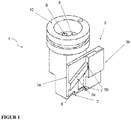
- FIG. 1 shows a three-dimensional view of the extrusion nozzle (1) according to the invention with opened nozzle opening (2).
- the extrusion die (1) can be connected via a connecting piece (10) with the extruder, not shown.
- the nozzle opening (2) is supplied with an extruded polymer melt.
- the slide (3) comprising a first part of slide (3a) and a second partial slide (3b) is arranged.
- the first partial slide (3a) and the second partial slide (3b) are connected via a sliding guide (5).
- the sliding guide (5) comprises a spring (5a) on the first partial slide (3a) and a groove (5b) on the second partial slide (3b).
- the first partial slide (3a) and the second partial slide (3b) change depending on their position, the opening width of the nozzle opening (2).
- the first partial slide (3a) has a notch (6) in the region of the nozzle opening (2) and the second partial slide has a notch (7).
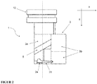
- FIG. 2 shows a side view of the extrusion die with opened nozzle opening (2).
- the structure corresponds to the in FIG. 1 described.
- the extrusion die (1) is connected via a connecting piece (10) to the extruder, not shown.
- the nozzle opening (2) is subdivided into a main opening (2a) and a bulge (2b) connected to the main opening (2a).
- the dashed line indicates the separation of the two openings of the nozzle opening (2).
- the transition from the main opening (2a) in the bulge (2b) is fluid, wherein the shape of the profiled strand of the main opening (2a), the shape of the lip of the bulge (2b) is predetermined.
- the extent of the nozzle opening (2) is predetermined via the first partial slide (3a) and the second partial slide (3b).
- the first partial slide (2a) essentially changes the opening width of the main opening (a) in the ⁇ -direction.
- the second partial slide (3b) essentially changes the opening width of the bulge (2b) in the x direction.
- the position of the x and ⁇ axis is in FIG. 2 pictured in the upper right corner of the picture.
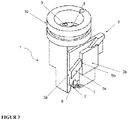
- FIG. 3 shows a spatial view of the extrusion die with partially closed nozzle opening (2).
- the structure corresponds to the in FIG. 1 described.
- a first partial slide (3a) and a second partial slide (3b) are arranged, which are connected via a sliding guide (5).
- the extent of the nozzle opening (2) is predetermined via the first partial slide (3a) and the second partial slide (3b).
- the second partial slide (3b) is displaced in the direction of the nozzle opening (2) and the first partial slide (3a) away from the nozzle opening (2).
- FIG. 4 shows a side view of the extrusion die with partially closed nozzle opening in the area lip and opened nozzle opening in the area spacer (2).
- the basic structure corresponds to that in FIG. 2 shown construction with a changed position of the first partial slide (3a) and the second partial slide (3b).
- the nozzle opening (2) is bounded in the region of the main opening (2a) by the first partial slide (3a) and in the region of the projection (2b) by the second partial slide (3b).
- An additional fine adjustment is possible on the first partial slide (3a) through the notch (6), preferably for rounding off the profile.
- the position of the x and ⁇ axis is in FIG. 4 pictured in the upper right corner of the picture.
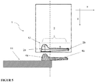
- FIG. 5 shows a schematic view of the nozzle opening (2) aligned over a substrate (11).
- the nozzle opening (2) comprises the main opening (2a) and the bulge (2b) along the dashed line.
- the main opening (2a) and the bulge (2b) preferably merge into one another.
- the bulge (2b) preferably comprises 30% to 70% of the maximum diameter of the nozzle opening (2).
- the maximum diameter is determined parallel to the surface to be coated (11).
- the height of the main opening (2a) is given by the axis (b).
- the resulting extruded strand (profiled strand) (4a) with lip (4b) corresponds to the main opening (2a) and the bulge (2b) of the nozzle opening (2).
- the geometry of the nozzle opening (2) can also from the in FIG. 5 shown image and assume a free, variable shape within the imaginary dashed rectangle of the maximum extent of the nozzle opening (12).
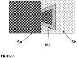
- FIG. 6 shows a schematic cross section of the sliding guide (5) using the example of the dovetail.
- the spring (5a) is freely movable within the groove (5b).
- a lubricant (5c) for example, a grease, mineral or silicone oil facilitates the movement of the spring (5a) and reduces the friction or flow resistance.
- the dovetail joint prevents disengagement of the sliding guide joint.
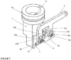
- FIG. 7 shows a three-dimensional view of the extrusion nozzle body (1) according to the invention with opened nozzle opening (2).
- the extrusion nozzle (1) can be connected via a connecting piece (16) with the extruder, not shown.
- Via a first feed channel (17) the nozzle opening (2) is supplied with an extruded polymer melt.
- Nozzle opening (2) is a horizontally movable guide slide (3) arranged.
- the guide slide (3) comprises a first guide slide arm (13a) with a first guide opening (13b) and a second guide slide arm (13c) with a second guide opening (13d).
- the extrusion die further comprises a first pivot profile element (14a) with a protruding first guide cylinder (6a) and a second pivot profile element (14b) with a protruding second guide cylinder (6b).
- the first pivot profile element (14a) and the second pivot profile element (14b) have a bulge (10).
- the shape of the bulge (18) like the shape of the nozzle opening (2), depends on the shape of the desired shaped article to be extruded.
- a notch (15) in the second pivot profile element (14b) allows a further variation of the molding to be extruded.
- FIG. 8 shows a side view of the extrusion die with opened nozzle opening (2).
- the structure corresponds to the in FIG. 7 described.
- the horizontally movable guide slide (3) is displaceable in the x direction.
- the extrusion nozzle body (1) is connected via a connecting piece (16) with the extruder, not shown.
- the nozzle opening (2) is divided into a main opening (2a) and a bulge (2b) connected to the main opening (2a).
- the dashed line indicates the separation of the two openings of the nozzle opening (2).
- the transition from the main opening (2a) into the bulge (2b) is fluid, the shape of the profiled strand being defined by the main opening (2a), the shape of the lip by the bulge (2b).
- the extension of the nozzle opening (2) is regulated via the first pivot profile element (14a) and the second pivot profile element (14b).
- the pivot profile elements (14a, 14b) are adjustable via the guide cylinder (6a, 6b).
- the guide cylinders (6a, 6b) are displaceable within the guide opening (13b, 13d) in the y-direction.
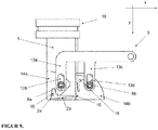
- FIG. 9 shows a further side view of the extrusion nozzle with partially closed nozzle opening (2).
- the structure corresponds to the in FIG. 1 and 2 described. Because of compared to FIG. 2 different position of the pivot profile elements (14a, 14b), the main opening (2a) of the nozzle opening (2) is smaller than in FIG. 2 ,
Landscapes
- Engineering & Computer Science (AREA)
- Mechanical Engineering (AREA)
- Manufacturing & Machinery (AREA)
- Extrusion Moulding Of Plastics Or The Like (AREA)
Claims (13)
- Buse d'extrusion pour déposer une bande profilée variable, comportant au moins :a. un corps de buse d'extrusion (1) ;b. un orifice de buse (2) ménagé dans le corps de buse d'extrusion (1), l'orifice de buse (2) comportant un orifice principal (2a) pour former la bande profilée et une indentation (2b) reliée à l'orifice principal (2a) pour former une lèvre (4b) reliée à la bande profilée (4a) ;c. un coulisseau (3) situé devant l'orifice de buse (2), le coulisseau (3) comportant une première partie de coulisseau (3a) et une seconde partie de coulisseau (3b) disposées l'une derrière l'autre et reliées l'une à l'autre par un guide coulissant (5), la première partie de coulisseau (3a) et la seconde partie de coulisseau (3b) étant couplées pour être solidaires en mouvement et la première partie de coulisseau (3a) étant apte à coulisser verticalement pour diminuer l'orifice principal (2a) et la seconde partie de coulisseau (3b) étant apte à coulisser horizontalement pour diminuer l'indentation (2b).
- Buse d'extrusion selon la revendication 1, dans laquelle le guide coulissant (5) comporte une languette (5a) et une rainure (5b), un guide par complémentarité de formes, en particulier une queue d'aronde, ou une rainure en T, de façon particulièrement préférée un assemblage à queue d'aronde.
- Buse d'extrusion selon l'une des revendications 1 ou 2, dans laquelle le guide coulissant (5) comporte un lubrifiant (5c).
- Buse d'extrusion selon l'une des revendications 1 à 3, dans laquelle la première partie de coulisseau (3a) présente une encoche (6) dans la région de l'orifice de buse (2).
- Buse d'extrusion selon l'une des revendications 1 à 4, dans laquelle la seconde partie de coulisseau (3b) présente une encoche (7) dans la région de l'orifice de buse (2).
- Buse d'extrusion selon l'une des revendications 1 à 5, dans laquelle le corps de buse d'extrusion (1) présente un premier canal d'amenée (8) et un second canal d'amenée (9).
- Buse d'extrusion selon la revendication 6, dans laquelle le premier canal d'amenée (8) et/ou le second canal d'amenée (9) contiennent des soupapes de commande.
- Buse d'extrusion selon l'une des revendications 1 à 7, dans laquelle l'orifice de buse (2) présente une surface (12) à l'intérieur d'un rectangle fictif ayant les longueurs de côté 5 mm à 50 mm et 2 mm à 20 mm, de préférence ayant les longueurs de côté 10 mm à 30 mm et 5 mm à 15 mm.
- Buse d'extrusion pour déposer une bande profilée variable, comportant au moins :a. un corps de buse d'extrusion (1) ;b. un orifice de buse (2) ménagé dans le corps de buse d'extrusion (1) ;c. un coulisseau de guidage (3) déplaçable horizontalement devant l'orifice de buse (2), comportantun premier bras de coulisseau de guidage (13a) ayant un premier orifice de guidage (13b) et un second bras de coulisseau de guidage (13c) ayant un second orifice de guidage (13d),un premier élément profilé pivotant (14a) ayant un premier cylindre de guidage (6a) faisant saillie et un second élément profilé pivotant (14b) ayant un second cylindre de guidage faisant saillie (6b), le premier élément profilé pivotant (14a) et le second élément profilé pivotant (14b) présentant une indentation (18) etd. le premier cylindre de guidage (6b) étant monté déplaçable à l'intérieur du premier orifice de guidage (13b) et le second cylindre de guidage (6b) étant monté déplaçable à l'intérieur du second orifice de guidage (13d), et le premier élément profilé pivotant (14a) et le second élément profilé pivotant (14b) étant aptes à tourner simultanément parallèlement au coulisseau de guidage (3) devant l'orifice de buse (2).
- Buse d'extrusion selon la revendication 9, dans laquelle le premier orifice de guidage (13b) et/ou le second orifice de guidage (13d) comportent un lubrifiant (13e).
- Buse d'extrusion selon l'une des revendications 9 ou 10, dans laquelle le coulisseau de guidage (3) est relié au corps de buse d'extrusion (1) par un guide coulissant, de préférence une queue d'aronde.
- Procédé pour l'extrusion continue d'une bande profilée variable sur un substrat (12), dans lequel un polymère est appliqué sur un substrat à l'aide d'une buse d'extrusion selon l'une des revendications 1 à 11.
- Utilisation de la buse d'extrusion selon l'une des revendications 1 à 11 pour l'extrusion d'une bande profilée variable sur du verre, des polymères ou des métaux, en particulier d'une bande profilée variable sur un vitrage d'automobile, un revêtement de plancher ou des tuyaux flexibles.
Priority Applications (1)
| Application Number | Priority Date | Filing Date | Title |
|---|---|---|---|
| EP12783994.2A EP2794227B1 (fr) | 2011-12-23 | 2012-11-08 | Buse d'extrusion et procédé destinée à produire une bande profilée variable en continu |
Applications Claiming Priority (3)
| Application Number | Priority Date | Filing Date | Title |
|---|---|---|---|
| EP11195528 | 2011-12-23 | ||
| EP12783994.2A EP2794227B1 (fr) | 2011-12-23 | 2012-11-08 | Buse d'extrusion et procédé destinée à produire une bande profilée variable en continu |
| PCT/EP2012/072112 WO2013091988A1 (fr) | 2011-12-23 | 2012-11-08 | Filière d'extrusion et procédé de production d'un profilé à variation continue |
Publications (2)
| Publication Number | Publication Date |
|---|---|
| EP2794227A1 EP2794227A1 (fr) | 2014-10-29 |
| EP2794227B1 true EP2794227B1 (fr) | 2018-11-07 |
Family
ID=47148809
Family Applications (1)
| Application Number | Title | Priority Date | Filing Date |
|---|---|---|---|
| EP12783994.2A Not-in-force EP2794227B1 (fr) | 2011-12-23 | 2012-11-08 | Buse d'extrusion et procédé destinée à produire une bande profilée variable en continu |
Country Status (2)
| Country | Link |
|---|---|
| EP (1) | EP2794227B1 (fr) |
| WO (1) | WO2013091988A1 (fr) |
Cited By (1)
| Publication number | Priority date | Publication date | Assignee | Title |
|---|---|---|---|---|
| WO2025045443A1 (fr) | 2023-08-30 | 2025-03-06 | Saint-Gobain Sekurit France | Buse d'extrusion et procédé d'évacuation d'un profil extrudé |
Families Citing this family (3)
| Publication number | Priority date | Publication date | Assignee | Title |
|---|---|---|---|---|
| DE202020005597U1 (de) | 2020-01-16 | 2021-10-07 | Saint-Gobain Glass France | Extrusionsdüse |
| EP3851626A1 (fr) | 2020-01-16 | 2021-07-21 | Saint-Gobain Glass France | Buse d'extrusion, procédé d'extrusion et utilisation de la buse d'extrusion |
| CN115816794B (zh) * | 2022-11-30 | 2025-05-23 | 浙江精诚模具机械有限公司 | 一种挤出模头平移式快速开口装置 |
Citations (2)
| Publication number | Priority date | Publication date | Assignee | Title |
|---|---|---|---|---|
| EP0634263A1 (fr) * | 1993-06-25 | 1995-01-18 | Asahi Glass Company Ltd. | Procédé de fabrication d'un chassis de fenêtre et panneau de fenêtre avec un chassis de fenêtre |
| DE69718385T2 (de) * | 1996-01-30 | 2003-11-20 | Kashimoto Forming Industries Co., Ltd. | Langgestrecktes verbundmaterial von dem der querschnitt in längsrichtung variiert, verfahren und vorrichtung zu dessen herstellung |
Family Cites Families (10)
| Publication number | Priority date | Publication date | Assignee | Title |
|---|---|---|---|---|
| DE3148212A1 (de) * | 1981-12-05 | 1983-06-09 | Continental Gummi-Werke Ag, 3000 Hannover | Strangpresse |
| DE3930414C2 (de) | 1989-09-12 | 2002-01-10 | Saint Gobain Sekurit D Gmbh | Verfahren und Vorrichtung zur Herstellung einer für die Direktverklebung mit dem Befestigungsflansch einer Fensteröffnung vorgesehenen Glasscheibe |
| IT1232133B (it) * | 1989-07-05 | 1992-01-23 | Saiag Spa | Guarnizione di tenuta per carrozzerie di autoveicoli, testa di estrusione e procedimento per realizzare tale guarnizione |
| US5233805A (en) * | 1989-10-14 | 1993-08-10 | Tokai Kogyo Kabushiki Kaisha | Molding for automotive front glass and molding apparatus |
| USRE37737E1 (en) * | 1990-09-06 | 2002-06-11 | Tokai Kogyo Kabushiki Kaisha | Automobile windshield molding and method of producing the same |
| DE4232554C1 (de) | 1992-09-29 | 1994-01-05 | Ver Glaswerke Gmbh | Verfahren zur Herstellung einer mit einem angeformten Rahmen aus einem thermoplastischen Polymer versehenen Glasscheibe und Vorrichtung zur Durchführung des Verfahrens |
| JPH08197606A (ja) * | 1995-01-31 | 1996-08-06 | Kinugawa Rubber Ind Co Ltd | 自動車用ウインドモールとその製造方法 |
| DE19604397C1 (de) | 1996-02-07 | 1997-07-31 | Sekurit Saint Gobain Deutsch | Vorrichtung zum Anextrudieren eines rahmenartigen Profilstrangs an eine Glasscheibe |
| US6106047A (en) * | 1996-08-21 | 2000-08-22 | Kinugawa Rubber Ind. Co., Ltd. | Window molding, method and apparatus for producing same |
| JP3234161B2 (ja) * | 1996-09-17 | 2001-12-04 | 鬼怒川ゴム工業株式会社 | 自動車用ウインドモールの製造方法および製造装置 |
-
2012
- 2012-11-08 EP EP12783994.2A patent/EP2794227B1/fr not_active Not-in-force
- 2012-11-08 WO PCT/EP2012/072112 patent/WO2013091988A1/fr not_active Ceased
Patent Citations (2)
| Publication number | Priority date | Publication date | Assignee | Title |
|---|---|---|---|---|
| EP0634263A1 (fr) * | 1993-06-25 | 1995-01-18 | Asahi Glass Company Ltd. | Procédé de fabrication d'un chassis de fenêtre et panneau de fenêtre avec un chassis de fenêtre |
| DE69718385T2 (de) * | 1996-01-30 | 2003-11-20 | Kashimoto Forming Industries Co., Ltd. | Langgestrecktes verbundmaterial von dem der querschnitt in längsrichtung variiert, verfahren und vorrichtung zu dessen herstellung |
Cited By (1)
| Publication number | Priority date | Publication date | Assignee | Title |
|---|---|---|---|---|
| WO2025045443A1 (fr) | 2023-08-30 | 2025-03-06 | Saint-Gobain Sekurit France | Buse d'extrusion et procédé d'évacuation d'un profil extrudé |
Also Published As
| Publication number | Publication date |
|---|---|
| EP2794227A1 (fr) | 2014-10-29 |
| WO2013091988A1 (fr) | 2013-06-27 |
Similar Documents
| Publication | Publication Date | Title |
|---|---|---|
| DE4006006C1 (fr) | ||
| DE4123256C1 (fr) | ||
| DE19961706B4 (de) | Verbindung einer Fahrzeugscheibe mit einem angrenzenden Bauteil | |
| DE60009378T2 (de) | Fahrzeugdichtung | |
| DE69318512T2 (de) | Verfahren zum Herstellen einer Autoglasscheibe mit einem Umfangsrahmen aus Elastomermaterial mit bestimmter Formgebung | |
| EP2794227B1 (fr) | Buse d'extrusion et procédé destinée à produire une bande profilée variable en continu | |
| DE69003520T2 (de) | Verfahren und Vorrichtung zur Herstellung einer Dichtung um eine Glasscheibe, z.B. am Rand von einer Frontscheibe, und derartige Frontscheibe. | |
| DE69118080T3 (de) | Vorrichtung um ein Formteil am Rand einer Glasscheibe anzuformen | |
| DE69321649T2 (de) | Verfahren zur Herstellung von Fensterglas mit Kunststoffrahmen | |
| DE69705759T2 (de) | Scheibenlaufrad mit zusammengesetzten Verstärkungsmaterialien | |
| EP1935694B1 (fr) | Profil d'étanchéité, en particulier destiné à étancher entre une porte et la carrosserie d'un véhicule automobile | |
| DE69423145T2 (de) | Verfahren zur Herstellung von Fensterrahmen und Fensterpaneelen mit Fensterrahmen | |
| DE69420381T2 (de) | Strangpressdüse, Verfahren zum Herstellen eines Formlings auf einen plattenförmigen Gegenstand und plattenförmiger Gegenstand mit hergestelltem Formling | |
| EP0081093B1 (fr) | Extrudeuse | |
| EP1634753A1 (fr) | Corps profilé, en particulier bandes de fixation pour pare-brises | |
| DE19604397C1 (de) | Vorrichtung zum Anextrudieren eines rahmenartigen Profilstrangs an eine Glasscheibe | |
| DE102008001347A1 (de) | Verfahren zur Herstellung von Strangextrudaten | |
| DE102012209233A1 (de) | Wischgummiprofil und Verfahren zur Herstellung desselben | |
| DE69513212T2 (de) | Verfahren zum Strangpressen von Formteilen auf plattenförmige Gegenstände | |
| WO2025045443A1 (fr) | Buse d'extrusion et procédé d'évacuation d'un profil extrudé | |
| EP3441245B1 (fr) | Dispositif d'aération | |
| DE102007034328A1 (de) | Strangextrudat sowie Verfahren zu seiner Herstellung und Verwendung | |
| DE69730786T2 (de) | Verfahren zur Herstellung, durch Extrusion, eines Profils mit lokal veränderlichem Querschnitt | |
| DE69322130T2 (de) | Verfahren zur Herstellung von Gegenständen aus vernetzbarem Kunststoff | |
| EP2396186B1 (fr) | Revêtement durci par ultraviolets (uv) réticulable sur fibres floquées pour une performance améliorée |
Legal Events
| Date | Code | Title | Description |
|---|---|---|---|
| PUAI | Public reference made under article 153(3) epc to a published international application that has entered the european phase |
Free format text: ORIGINAL CODE: 0009012 |
|
| 17P | Request for examination filed |
Effective date: 20140516 |
|
| AK | Designated contracting states |
Kind code of ref document: A1 Designated state(s): AL AT BE BG CH CY CZ DE DK EE ES FI FR GB GR HR HU IE IS IT LI LT LU LV MC MK MT NL NO PL PT RO RS SE SI SK SM TR |
|
| DAX | Request for extension of the european patent (deleted) | ||
| STAA | Information on the status of an ep patent application or granted ep patent |
Free format text: STATUS: EXAMINATION IS IN PROGRESS |
|
| 17Q | First examination report despatched |
Effective date: 20170418 |
|
| GRAP | Despatch of communication of intention to grant a patent |
Free format text: ORIGINAL CODE: EPIDOSNIGR1 |
|
| STAA | Information on the status of an ep patent application or granted ep patent |
Free format text: STATUS: GRANT OF PATENT IS INTENDED |
|
| RIC1 | Information provided on ipc code assigned before grant |
Ipc: B29C 47/94 20060101ALN20180626BHEP Ipc: B29C 47/92 20060101ALN20180626BHEP Ipc: B29C 47/12 20060101ALI20180626BHEP Ipc: B29C 47/16 20060101ALI20180626BHEP Ipc: B29C 47/02 20060101AFI20180626BHEP |
|
| RIC1 | Information provided on ipc code assigned before grant |
Ipc: B29C 47/12 20060101ALI20180711BHEP Ipc: B29C 47/16 20060101ALI20180711BHEP Ipc: B29C 47/02 20060101AFI20180711BHEP Ipc: B29C 47/92 20060101ALN20180711BHEP Ipc: B29C 47/94 20060101ALN20180711BHEP |
|
| RIC1 | Information provided on ipc code assigned before grant |
Ipc: B29C 47/16 20060101ALI20180718BHEP Ipc: B29C 47/12 20060101ALI20180718BHEP Ipc: B29C 47/94 20060101ALN20180718BHEP Ipc: B29C 47/92 20060101ALN20180718BHEP Ipc: B29C 47/02 20060101AFI20180718BHEP |
|
| INTG | Intention to grant announced |
Effective date: 20180801 |
|
| GRAS | Grant fee paid |
Free format text: ORIGINAL CODE: EPIDOSNIGR3 |
|
| GRAA | (expected) grant |
Free format text: ORIGINAL CODE: 0009210 |
|
| STAA | Information on the status of an ep patent application or granted ep patent |
Free format text: STATUS: THE PATENT HAS BEEN GRANTED |
|
| AK | Designated contracting states |
Kind code of ref document: B1 Designated state(s): AL AT BE BG CH CY CZ DE DK EE ES FI FR GB GR HR HU IE IS IT LI LT LU LV MC MK MT NL NO PL PT RO RS SE SI SK SM TR |
|
| REG | Reference to a national code |
Ref country code: GB Ref legal event code: FG4D Free format text: NOT ENGLISH |
|
| REG | Reference to a national code |
Ref country code: CH Ref legal event code: EP Ref country code: AT Ref legal event code: REF Ref document number: 1061534 Country of ref document: AT Kind code of ref document: T Effective date: 20181115 |
|
| REG | Reference to a national code |
Ref country code: DE Ref legal event code: R079 Ref document number: 502012013785 Country of ref document: DE Free format text: PREVIOUS MAIN CLASS: B29C0047020000 Ipc: B29C0048150000 |
|
| REG | Reference to a national code |
Ref country code: IE Ref legal event code: FG4D Free format text: LANGUAGE OF EP DOCUMENT: GERMAN |
|
| REG | Reference to a national code |
Ref country code: DE Ref legal event code: R096 Ref document number: 502012013785 Country of ref document: DE |
|
| REG | Reference to a national code |
Ref country code: NL Ref legal event code: FP |
|
| PGFP | Annual fee paid to national office [announced via postgrant information from national office to epo] |
Ref country code: FR Payment date: 20181213 Year of fee payment: 8 |
|
| REG | Reference to a national code |
Ref country code: SE Ref legal event code: TRGR |
|
| REG | Reference to a national code |
Ref country code: LT Ref legal event code: MG4D |
|
| PG25 | Lapsed in a contracting state [announced via postgrant information from national office to epo] |
Ref country code: IS Free format text: LAPSE BECAUSE OF FAILURE TO SUBMIT A TRANSLATION OF THE DESCRIPTION OR TO PAY THE FEE WITHIN THE PRESCRIBED TIME-LIMIT Effective date: 20190307 Ref country code: NO Free format text: LAPSE BECAUSE OF FAILURE TO SUBMIT A TRANSLATION OF THE DESCRIPTION OR TO PAY THE FEE WITHIN THE PRESCRIBED TIME-LIMIT Effective date: 20190207 Ref country code: LT Free format text: LAPSE BECAUSE OF FAILURE TO SUBMIT A TRANSLATION OF THE DESCRIPTION OR TO PAY THE FEE WITHIN THE PRESCRIBED TIME-LIMIT Effective date: 20181107 Ref country code: BG Free format text: LAPSE BECAUSE OF FAILURE TO SUBMIT A TRANSLATION OF THE DESCRIPTION OR TO PAY THE FEE WITHIN THE PRESCRIBED TIME-LIMIT Effective date: 20190207 Ref country code: HR Free format text: LAPSE BECAUSE OF FAILURE TO SUBMIT A TRANSLATION OF THE DESCRIPTION OR TO PAY THE FEE WITHIN THE PRESCRIBED TIME-LIMIT Effective date: 20181107 Ref country code: ES Free format text: LAPSE BECAUSE OF FAILURE TO SUBMIT A TRANSLATION OF THE DESCRIPTION OR TO PAY THE FEE WITHIN THE PRESCRIBED TIME-LIMIT Effective date: 20181107 Ref country code: LV Free format text: LAPSE BECAUSE OF FAILURE TO SUBMIT A TRANSLATION OF THE DESCRIPTION OR TO PAY THE FEE WITHIN THE PRESCRIBED TIME-LIMIT Effective date: 20181107 Ref country code: FI Free format text: LAPSE BECAUSE OF FAILURE TO SUBMIT A TRANSLATION OF THE DESCRIPTION OR TO PAY THE FEE WITHIN THE PRESCRIBED TIME-LIMIT Effective date: 20181107 |
|
| PG25 | Lapsed in a contracting state [announced via postgrant information from national office to epo] |
Ref country code: PT Free format text: LAPSE BECAUSE OF FAILURE TO SUBMIT A TRANSLATION OF THE DESCRIPTION OR TO PAY THE FEE WITHIN THE PRESCRIBED TIME-LIMIT Effective date: 20190307 Ref country code: AL Free format text: LAPSE BECAUSE OF FAILURE TO SUBMIT A TRANSLATION OF THE DESCRIPTION OR TO PAY THE FEE WITHIN THE PRESCRIBED TIME-LIMIT Effective date: 20181107 Ref country code: RS Free format text: LAPSE BECAUSE OF FAILURE TO SUBMIT A TRANSLATION OF THE DESCRIPTION OR TO PAY THE FEE WITHIN THE PRESCRIBED TIME-LIMIT Effective date: 20181107 Ref country code: GR Free format text: LAPSE BECAUSE OF FAILURE TO SUBMIT A TRANSLATION OF THE DESCRIPTION OR TO PAY THE FEE WITHIN THE PRESCRIBED TIME-LIMIT Effective date: 20190208 |
|
| REG | Reference to a national code |
Ref country code: CH Ref legal event code: PL |
|
| PG25 | Lapsed in a contracting state [announced via postgrant information from national office to epo] |
Ref country code: IT Free format text: LAPSE BECAUSE OF FAILURE TO SUBMIT A TRANSLATION OF THE DESCRIPTION OR TO PAY THE FEE WITHIN THE PRESCRIBED TIME-LIMIT Effective date: 20181107 Ref country code: CZ Free format text: LAPSE BECAUSE OF FAILURE TO SUBMIT A TRANSLATION OF THE DESCRIPTION OR TO PAY THE FEE WITHIN THE PRESCRIBED TIME-LIMIT Effective date: 20181107 Ref country code: DK Free format text: LAPSE BECAUSE OF FAILURE TO SUBMIT A TRANSLATION OF THE DESCRIPTION OR TO PAY THE FEE WITHIN THE PRESCRIBED TIME-LIMIT Effective date: 20181107 Ref country code: PL Free format text: LAPSE BECAUSE OF FAILURE TO SUBMIT A TRANSLATION OF THE DESCRIPTION OR TO PAY THE FEE WITHIN THE PRESCRIBED TIME-LIMIT Effective date: 20181107 |
|
| REG | Reference to a national code |
Ref country code: DE Ref legal event code: R097 Ref document number: 502012013785 Country of ref document: DE |
|
| REG | Reference to a national code |
Ref country code: IE Ref legal event code: MM4A |
|
| PG25 | Lapsed in a contracting state [announced via postgrant information from national office to epo] |
Ref country code: MC Free format text: LAPSE BECAUSE OF FAILURE TO SUBMIT A TRANSLATION OF THE DESCRIPTION OR TO PAY THE FEE WITHIN THE PRESCRIBED TIME-LIMIT Effective date: 20181107 Ref country code: CH Free format text: LAPSE BECAUSE OF NON-PAYMENT OF DUE FEES Effective date: 20181130 Ref country code: LI Free format text: LAPSE BECAUSE OF NON-PAYMENT OF DUE FEES Effective date: 20181130 Ref country code: RO Free format text: LAPSE BECAUSE OF FAILURE TO SUBMIT A TRANSLATION OF THE DESCRIPTION OR TO PAY THE FEE WITHIN THE PRESCRIBED TIME-LIMIT Effective date: 20181107 Ref country code: SK Free format text: LAPSE BECAUSE OF FAILURE TO SUBMIT A TRANSLATION OF THE DESCRIPTION OR TO PAY THE FEE WITHIN THE PRESCRIBED TIME-LIMIT Effective date: 20181107 Ref country code: EE Free format text: LAPSE BECAUSE OF FAILURE TO SUBMIT A TRANSLATION OF THE DESCRIPTION OR TO PAY THE FEE WITHIN THE PRESCRIBED TIME-LIMIT Effective date: 20181107 Ref country code: SM Free format text: LAPSE BECAUSE OF FAILURE TO SUBMIT A TRANSLATION OF THE DESCRIPTION OR TO PAY THE FEE WITHIN THE PRESCRIBED TIME-LIMIT Effective date: 20181107 |
|
| PLBE | No opposition filed within time limit |
Free format text: ORIGINAL CODE: 0009261 |
|
| STAA | Information on the status of an ep patent application or granted ep patent |
Free format text: STATUS: NO OPPOSITION FILED WITHIN TIME LIMIT |
|
| 26N | No opposition filed |
Effective date: 20190808 |
|
| PG25 | Lapsed in a contracting state [announced via postgrant information from national office to epo] |
Ref country code: IE Free format text: LAPSE BECAUSE OF NON-PAYMENT OF DUE FEES Effective date: 20181108 Ref country code: SI Free format text: LAPSE BECAUSE OF FAILURE TO SUBMIT A TRANSLATION OF THE DESCRIPTION OR TO PAY THE FEE WITHIN THE PRESCRIBED TIME-LIMIT Effective date: 20181107 |
|
| PGFP | Annual fee paid to national office [announced via postgrant information from national office to epo] |
Ref country code: LU Payment date: 20191024 Year of fee payment: 8 |
|
| REG | Reference to a national code |
Ref country code: AT Ref legal event code: MM01 Ref document number: 1061534 Country of ref document: AT Kind code of ref document: T Effective date: 20181108 |
|
| PG25 | Lapsed in a contracting state [announced via postgrant information from national office to epo] |
Ref country code: AT Free format text: LAPSE BECAUSE OF NON-PAYMENT OF DUE FEES Effective date: 20181108 Ref country code: MT Free format text: LAPSE BECAUSE OF FAILURE TO SUBMIT A TRANSLATION OF THE DESCRIPTION OR TO PAY THE FEE WITHIN THE PRESCRIBED TIME-LIMIT Effective date: 20181107 |
|
| PGFP | Annual fee paid to national office [announced via postgrant information from national office to epo] |
Ref country code: DE Payment date: 20191029 Year of fee payment: 8 Ref country code: SE Payment date: 20191111 Year of fee payment: 8 Ref country code: NL Payment date: 20191114 Year of fee payment: 8 |
|
| PGFP | Annual fee paid to national office [announced via postgrant information from national office to epo] |
Ref country code: BE Payment date: 20191017 Year of fee payment: 8 |
|
| PG25 | Lapsed in a contracting state [announced via postgrant information from national office to epo] |
Ref country code: TR Free format text: LAPSE BECAUSE OF FAILURE TO SUBMIT A TRANSLATION OF THE DESCRIPTION OR TO PAY THE FEE WITHIN THE PRESCRIBED TIME-LIMIT Effective date: 20181107 |
|
| PGFP | Annual fee paid to national office [announced via postgrant information from national office to epo] |
Ref country code: GB Payment date: 20191108 Year of fee payment: 8 |
|
| PG25 | Lapsed in a contracting state [announced via postgrant information from national office to epo] |
Ref country code: CY Free format text: LAPSE BECAUSE OF FAILURE TO SUBMIT A TRANSLATION OF THE DESCRIPTION OR TO PAY THE FEE WITHIN THE PRESCRIBED TIME-LIMIT Effective date: 20181107 Ref country code: MK Free format text: LAPSE BECAUSE OF NON-PAYMENT OF DUE FEES Effective date: 20181107 Ref country code: HU Free format text: LAPSE BECAUSE OF FAILURE TO SUBMIT A TRANSLATION OF THE DESCRIPTION OR TO PAY THE FEE WITHIN THE PRESCRIBED TIME-LIMIT; INVALID AB INITIO Effective date: 20121108 |
|
| REG | Reference to a national code |
Ref country code: DE Ref legal event code: R119 Ref document number: 502012013785 Country of ref document: DE |
|
| REG | Reference to a national code |
Ref country code: SE Ref legal event code: EUG |
|
| REG | Reference to a national code |
Ref country code: NL Ref legal event code: MM Effective date: 20201201 |
|
| GBPC | Gb: european patent ceased through non-payment of renewal fee |
Effective date: 20201108 |
|
| PG25 | Lapsed in a contracting state [announced via postgrant information from national office to epo] |
Ref country code: LU Free format text: LAPSE BECAUSE OF NON-PAYMENT OF DUE FEES Effective date: 20201108 |
|
| REG | Reference to a national code |
Ref country code: BE Ref legal event code: MM Effective date: 20201130 |
|
| PG25 | Lapsed in a contracting state [announced via postgrant information from national office to epo] |
Ref country code: NL Free format text: LAPSE BECAUSE OF NON-PAYMENT OF DUE FEES Effective date: 20201201 Ref country code: SE Free format text: LAPSE BECAUSE OF NON-PAYMENT OF DUE FEES Effective date: 20201109 |
|
| PG25 | Lapsed in a contracting state [announced via postgrant information from national office to epo] |
Ref country code: FR Free format text: LAPSE BECAUSE OF NON-PAYMENT OF DUE FEES Effective date: 20201130 |
|
| PG25 | Lapsed in a contracting state [announced via postgrant information from national office to epo] |
Ref country code: DE Free format text: LAPSE BECAUSE OF NON-PAYMENT OF DUE FEES Effective date: 20210601 Ref country code: GB Free format text: LAPSE BECAUSE OF NON-PAYMENT OF DUE FEES Effective date: 20201108 |
|
| PG25 | Lapsed in a contracting state [announced via postgrant information from national office to epo] |
Ref country code: BE Free format text: LAPSE BECAUSE OF NON-PAYMENT OF DUE FEES Effective date: 20201130 |