EP2799162A1 - Moule de coulée continue - Google Patents
Moule de coulée continue Download PDFInfo
- Publication number
- EP2799162A1 EP2799162A1 EP20120861285 EP12861285A EP2799162A1 EP 2799162 A1 EP2799162 A1 EP 2799162A1 EP 20120861285 EP20120861285 EP 20120861285 EP 12861285 A EP12861285 A EP 12861285A EP 2799162 A1 EP2799162 A1 EP 2799162A1
- Authority
- EP
- European Patent Office
- Prior art keywords
- slab
- short
- mold
- incline
- projection
- Prior art date
- Legal status (The legal status is an assumption and is not a legal conclusion. Google has not performed a legal analysis and makes no representation as to the accuracy of the status listed.)
- Granted
Links
Images





Classifications
-
- B—PERFORMING OPERATIONS; TRANSPORTING
- B22—CASTING; POWDER METALLURGY
- B22D—CASTING OF METALS; CASTING OF OTHER SUBSTANCES BY THE SAME PROCESSES OR DEVICES
- B22D11/00—Continuous casting of metals, i.e. casting in indefinite lengths
- B22D11/04—Continuous casting of metals, i.e. casting in indefinite lengths into open-ended moulds
-
- B—PERFORMING OPERATIONS; TRANSPORTING
- B22—CASTING; POWDER METALLURGY
- B22D—CASTING OF METALS; CASTING OF OTHER SUBSTANCES BY THE SAME PROCESSES OR DEVICES
- B22D11/00—Continuous casting of metals, i.e. casting in indefinite lengths
- B22D11/04—Continuous casting of metals, i.e. casting in indefinite lengths into open-ended moulds
- B22D11/05—Continuous casting of metals, i.e. casting in indefinite lengths into open-ended moulds into moulds having adjustable walls
-
- B—PERFORMING OPERATIONS; TRANSPORTING
- B22—CASTING; POWDER METALLURGY
- B22D—CASTING OF METALS; CASTING OF OTHER SUBSTANCES BY THE SAME PROCESSES OR DEVICES
- B22D11/00—Continuous casting of metals, i.e. casting in indefinite lengths
- B22D11/04—Continuous casting of metals, i.e. casting in indefinite lengths into open-ended moulds
- B22D11/0406—Moulds with special profile
-
- B—PERFORMING OPERATIONS; TRANSPORTING
- B22—CASTING; POWDER METALLURGY
- B22D—CASTING OF METALS; CASTING OF OTHER SUBSTANCES BY THE SAME PROCESSES OR DEVICES
- B22D11/00—Continuous casting of metals, i.e. casting in indefinite lengths
- B22D11/04—Continuous casting of metals, i.e. casting in indefinite lengths into open-ended moulds
- B22D11/041—Continuous casting of metals, i.e. casting in indefinite lengths into open-ended moulds for vertical casting
Definitions
- the present invention relates to a continuous casting mold for preventing corner cracks in a slab.
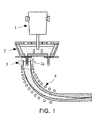
- FIG. 1 is a perspective view of a general continuous casting apparatus
- FIG. 2 is a perspective view of a mold 3 of the continuous casting apparatus of FIG. 1 .
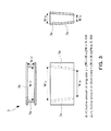
- FIG. 3 illustrates a front view, a top view, and a side view of the mold 3 of FIG. 2
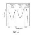
- FIG. 4 is a graph illustrating a brittle area of steel according to a temperature.
- liquid molten steel passes from a ladle 1 to a tundish 2 and is injected into the mold 3, thereby forming a solidified layer at a surface of a slab.
- the solidification of the liquid molten steel is completed while the slab is passing through a second cooling zone 4 including a plurality of guide rolls, thereby allowing slabs to be continuously produced.
- molten steel is injected into the mold 3 through a soak nozzle 2a and a solidified layer is formed from a surface of the molten steel at a short side of a mold 3a and a long side of a mold 3b and grows and becomes thicker.
- the solidified layer progressing downwardly, decreases in temperature and becomes contracts.
- the mold 3 does not compensate for such contraction, tension occurs in the solidified layer and cracks are formed therein.
- a bottom width is reduced in comparison with a top width, thereby allowing the mold 3 to incline.
- a shrinkage rate of long sides of the solidified layer is compensated by allowing the short side mold 3a to incline by reducing a bottom width W 1B of the long sides in comparison with a top width W 1T of the long sides.
- a shrinkage rate of short sides of the solidified layer is compensated by allowing the long side mold 3b to incline by reducing a bottom width W 2B of the short side mold 3a in comparison with a top width W 2T thereof.
- Corner cracks formed in slabs are closely related with a brittle area of steel.
- the steel has three brittle areas according to a temperature.
- malleability is small in an area among these areas, in which a surface temperature of a slab is from about 700°C to about 800°C (hereinafter, referred to as a third area brittle section), although a strain speed is low, cracks easily develop.
- the slab is cast to allow corners to be chamfered to restrict the temperature at the corners from being more rapidly reduced than other portions of the slab, thereby allowing the temperature of corners to be outside of a brittle section while the slab is being bent or leveled by the continuous casting apparatus.
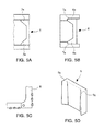
- prior art inventions for modifying a continuous casting mold as shown in FIGS. 5A to 5D , are disclosed in Patent Nos. EP0776714 and EP0409708 , Japanese Patent Laid-Open Publication No. hei 11-290995 , and Korean Patent Application No. KR2002-0084914 .
- Patent No. EP0776714 discloses a method of reducing inner cracks of a slab occurring while reducing an unsolidified portion of the slab, by allowing short sides of the slab to have a projecting shape using a short-side mold 5 .
- a chamfer of the slab includes a surface perpendicular to long sides instead of a flat incline, an effect of preventing a reduction in a temperature caused by chamfering is reduced in this portion and a corner is folded during a process of rolling the slab.
- a shape and a size of the projection 5a is identical at top and bottom thereof, a shrinkage rate of the chamfer is not compensated, thereby developing cracks.
- Patent No. EP0409708 may provide effects of preventing a folded groove in rolled steel by allowing a chamfer of a slab to be a flat incline by inserting a short-side mold 6 into a long side groove 7a and simultaneously with increasing durability by allowing a thickness of corners of a projection 6a to be great.
- a width of the short-side mold 6 and the top and the bottom have the same shape and size, a shrinkage rate of the slab at an incline surface of a chamfer is not compensated, thereby developing cracks in the chamfer.
- Japanese Patent Laid-Open Publication No. hei 11-290995 discloses a mold, in which both ends of a short-side mold 8 is processed as an arc to form a corner of a slab to have an arc shape. It is impossible to modify a width of the mold.
- the corner may be effective for preventing a reduction in a temperature of the corner and for increasing durability of a metal plate of the corner due to the arc shape thereof.
- the corner of the slab having the arc shape has the same shape at top and bottom, a shrinkage rate of a solidified layer of an arc is not compensated, thereby developing cracks between surfaces.
- Korean Patent Application No. KR2002-0084915 discloses a short-side mold 9 provided with a projection 9a forming a chamfer at corners of a slab, which increases in size at a lower portion to prevent corner cracks of the slab and cracks between surfaces. Since the projection 9a increases downwards, a length of the short-side mold 9 except the projection 9a is reduced at a lower portion thereof, thereby compensating for a shrinkage rate of the slab. However, since a length of an incline surface of the projection 9a increases at a lower portion at a chamfer of the slab, the shrinkage rate of the slab is not compensated, thereby developing cracks between surfaces at the chamfer.
- An aspect of the present invention provides a continuous casting mold for compensating for a shrinkage rate of a slab and reducing the abrasion of the mold.
- a continuous casting mold tapered downwards including two long-side molds and two short-side molds sealing a space between the two long-side molds and formed with projections on both ends thereof to form chamfers at corners of a slab, in which the projection of the short-side mold 40 is reduced downwards to compensate a shrinkage amount of the slab.
- the short-side mold toward a bottom thereof, may decrease in a width of an incline surface of the projection 42 and a width of a central surface 44a not projecting.
- the short-side mold toward a bottom thereof, decreases in an incline angle of the incline surface of the projection.
- an incline angle of an incline surface of the projection is from about 20° to about 70°.
- a difference between a top angle and a bottom angle at the incline angle of the incline surface of the projection may be 10° or less.
- chamfers are formed on corners of a slab, thereby preventing a rapid decrease in a temperature at the corners during a continuous-casting process. Also, a brittle section of a third area is avoided during a process of bending or leveling the slab, thereby reducing an occurrence rate of the corner cracks.
- the slab in the mold becomes solidified as progressing downwards, thereby being contracted.
- widths of an incline surface and a central surface not projecting, in contact with the chamfers of the slab become smaller, thereby compensating for a shrinkage amount of a short-side solidified layer of the slab to prevent cracks between surfaces at the chamfers.
- an incline angle of the projection is reduced toward a bottom of the short-side mold, thereby compensating for a shrinkage rate of a long-side solidified layer of the slab, which is more reduced than a tapered incline rate of the short-side mold downwards. Accordingly, it is possible to significantly reduce a degree of abrasion of the short-side mold.
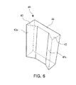
- FIG. 6 is a perspective view illustrating a short-side mold 40 of a continuous casting mold according to an embodiment of the present invention
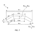
- FIG. 7 is a top view of the short-side mold 40.
- the continuous casting mold includes two long-side molds spaced corresponding to a thickness of a slab and two short-side molds 40 spaced corresponding to a width of the slab.
- two long-side molds are disposed to be spaced from each other corresponding to the thickness of the slab formed while molten steel is being solidified.
- two short-side molds 40 seal a space between the two long-side molds and are fastened to the long-side mold while being spaced from each other corresponding to the width of slab.
- the continuous casting mold formed of the long-side molds and the short-side molds 40 has a downward-tapered structure with open top and bottom.
- the short-side mold 40 is formed with projections 42 at both ends thereof to chamfer corners of the slab.
- the both ends of the short-side mold 40 project to be shaped corresponding to chamfers on the corners and incline toward a central surface 44a, thereby forming the projections 42 having an incline surface 42a corresponding to the chamfer of the slab.
- the short-side mold 40 is formed with the projections 42, the chamfers are formed on the corners of the slab, thereby preventing a rapid decrease in the temperature at the corners during a continuous-casting process. Also, a brittle section of a third area is avoided during the process of bending or leveling the slab, thereby reducing the corner cracks.
- a size of the projection 42 may be 15 mm or more in a thickness direction and a width direction of the short-side mold 40.
- the size of the projection 42 decreases toward a bottom of the projection 42 to compensate a shrinkage amount of a long-side solidified layer in the slab.
- a width of the incline surface 42a of the projection 42 is reduced and a width of the central surface 44a not projecting also is reduced.
- the width of the incline surface 42a becomes gradually narrower downwards and the width of the central surface 44a not projecting also becomes gradually smaller downwards.
- a bottom width IW B of the incline surface 42a may be smaller than a top width IW T thereof and a bottom width CW B of the central surface 44a may be smaller than a top CW T thereof.
- the slab in the mold becomes solidified as progressing downwards, thereby being contracted.
- the widths of the incline surface 42a and the central surface 44a not projecting, in contact with the chamfers of the slab become smaller, thereby compensating for a shrinkage amount of a short-side solidified layer to prevent cracks between surfaces at the chamfers.
- a horizontal difference W 2 ⁇ T - W 2 ⁇ B 2 (refer to FIG. 3 for W 2T and W 2B ) between top and bottom lateral edges of the projection 42, is formed to be greater than 0, thereby compensating the shrinkage amount of the short-side solidified layer.
- a horizontal difference W 1 ⁇ T - W 1 ⁇ B 2 (refer to FIG. 3 for W 1T and W 1B ) between top and bottom of the central surfaces 44a is formed to be greater than 0, thereby compensating the shrinkage amount of the long-side solidified layer.
- the long-side molds inclines with an incline surface amount of d 1 (d 1 >0) to compensate the shrinkage amount of the short-side solidified layer and the short-side mold 40 has an incline surface amount of d 2 (d 2 >0) to compensate the shrinkage amount of the long-side solidified layer.
- d 1 and d 2 as those of a general mold, have a value of from about 0.5% to about 1.5% (refer to FIG. 2 for W 1T , W 1B , W 2T , W 2B , d 1 , and d 2 ).
- S shown in FIG. 7 may have a value greater than 0.
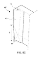
- the short-side mold 40 is formed to allow an incline angle of the incline surface 42a of the projection 42 to become smaller, as progressing downwards.
- a bottom angle ⁇ B may be smaller than a top angle ⁇ T at the incline surface 42a of the projection 42 of short-side molds 40', 40'', and 40'''.
- an incline angle of the projection 42 is reduced as progressing toward bottoms of the short-side molds 40', 40'', and 40''', thereby compensating for the shrinkage rate of the slab, which is more reduced than the tapered incline rate of the short-side mold downwards. Accordingly, it is possible to greatly reduce a degree of abrasion of the short-side mold.
- the bottom angle is smaller than the top angle, thereby forming another incline 42a on the incline surface 42a of the projection 42.
- a height of the other incline 42a on a bottom is designated as 'h'.
- the incline surface 42a of the projection 42 may be further formed with a plurality of inclines 42a.
- an incline angle of the incline surface 42a of the projection 42 may be from about 20° to about 70°.
- the incline angle of the incline surface 42a of the projection 42 is determined within a range of from about 0 to about 90°. When the incline angle is too small, that is, is reduced than 20°, an effect of chamfering a corner of the slab is reduced, thereby developing corner cracks.
- a difference between the top angle ⁇ T and the bottom angle ⁇ B at the incline angle of the incline surface 42a of the projection 42 may be 10° or less.
- the difference between an incline angle at a top surface and an incline surface at a bottom surface of the projection 42 becomes greater, a chamfer of the slab is distorted.
- the difference between the top angle ⁇ T and the bottom angle ⁇ B may be determined to be 10° or less.
- FIG. 9A is a table related to a condition of a short side mold in a continuous casting process
- FIG. 9B illustrates a result of measuring a temperature at a corner of a slab in accordance with the condition of the short side mold of in FIG. 9A .
- Test 1 is performed using a general mold
- Test 2 is performed using the short-side mold 40
- Test 3 is performed using the short-side mold 40'.
- Low carbon steel and medium carbon steel were produced as slabs having a width of from about 1000 to about 2000 mm and a thickness of about 250 mm through these molds and a crack occurrence rate of the slabs and a degree of abrasion of metal plates were shown.
- An incline surface amount of the short-side mold is allowed to vary within a range of from about 1.0 to about 1.3% according to the composition of steel and a width of a mold.
- the surface temperature of the corner of the slab is measured by a pyrometer horizontally moving on a top surface of the slab in a width direction in a position, in which the slab enters a leveling section in a continuous casting apparatus in a continuous casting process, which is shown in FIG. 9B .
- a temperature highly increases outwards from the corner of the slab. This is because a portion projected due to bulging at a short side of the slab is measured and shown by the pyrometer disposed perpendicularly to the top surface of the slab.
- an occurrence rate of corner cracks of the slab is about 4.1% when using the general mold but those of the Tests 2 and 3 are reduced to about 0.7%
- a degree of abrasion of the projection 42 of the short-side mold 40 is greater three times than a degree of abrasion of the general mold.
- the short-side mold 40 is formed with the projections 42, chamfers are formed on the corners of the slab, thereby preventing a rapid decrease in the temperature at the corners during the continuous-casting process. Also, a brittle section of a third area is avoided during a process of bending or leveling the slab, thereby reducing the corner cracks.
- the slab in the mold becomes solidified as progressing downwards, thereby being contracted.
- widths of the incline surface 42a and the central surface 44a not projecting, in contact with the chamfers of the slab become smaller, thereby compensating for a shrinkage amount of a short-side solidified layer to prevent cracks between surfaces at the chamfers.
- an incline angle of the projection 42 is reduced as progressing toward the bottom of the short-side mold 40, thereby appropriately compensating for a shrinkage rate of a long-side solidified layer of the slab, which is more reduced than the tapered incline rate of the short-side mold 40 downwards. Accordingly, it is possible to greatly reduce the degree of abrasion of the short-side mold 40.
Landscapes
- Engineering & Computer Science (AREA)
- Mechanical Engineering (AREA)
- Continuous Casting (AREA)
Applications Claiming Priority (2)
| Application Number | Priority Date | Filing Date | Title |
|---|---|---|---|
| KR20110142997A KR101360564B1 (ko) | 2011-12-27 | 2011-12-27 | 연속주조 주형 |
| PCT/KR2012/011290 WO2013100499A1 (fr) | 2011-12-27 | 2012-12-21 | Moule de coulée continue |
Publications (3)
| Publication Number | Publication Date |
|---|---|
| EP2799162A1 true EP2799162A1 (fr) | 2014-11-05 |
| EP2799162A4 EP2799162A4 (fr) | 2015-09-02 |
| EP2799162B1 EP2799162B1 (fr) | 2017-03-22 |
Family
ID=48697875
Family Applications (1)
| Application Number | Title | Priority Date | Filing Date |
|---|---|---|---|
| EP12861285.0A Active EP2799162B1 (fr) | 2011-12-27 | 2012-12-21 | Moule de coulée continue |
Country Status (5)
| Country | Link |
|---|---|
| EP (1) | EP2799162B1 (fr) |
| JP (1) | JP5933751B2 (fr) |
| KR (1) | KR101360564B1 (fr) |
| CN (1) | CN104023874B (fr) |
| WO (1) | WO2013100499A1 (fr) |
Cited By (2)
| Publication number | Priority date | Publication date | Assignee | Title |
|---|---|---|---|---|
| EP3795273A4 (fr) * | 2018-05-14 | 2021-03-24 | Posco | Moule |
| CN115697587A (zh) * | 2020-06-18 | 2023-02-03 | 杰富意钢铁株式会社 | 连续铸造方法 |
Families Citing this family (8)
| Publication number | Priority date | Publication date | Assignee | Title |
|---|---|---|---|---|
| KR101527857B1 (ko) * | 2013-12-24 | 2015-06-10 | 주식회사 포스코 | 주조용 몰드 |
| WO2016013186A1 (fr) * | 2014-07-24 | 2016-01-28 | Jfeスチール株式会社 | Procédé de coulée continue d'acier |
| KR101969112B1 (ko) * | 2017-09-12 | 2019-04-15 | 주식회사 포스코 | 주형 |
| CN110252981A (zh) * | 2019-06-10 | 2019-09-20 | 邢台钢铁有限责任公司 | 减轻轴承钢大方坯内部质量缺陷的连铸工艺 |
| WO2021256243A1 (fr) * | 2020-06-18 | 2021-12-23 | Jfeスチール株式会社 | Procédé de coulée continue |
| KR102441319B1 (ko) * | 2020-12-17 | 2022-09-08 | 주식회사 포스코 | 주형 |
| JP7741378B2 (ja) * | 2021-11-09 | 2025-09-18 | 日本製鉄株式会社 | 鋼の連続鋳造方法 |
| KR20230083055A (ko) * | 2021-12-02 | 2023-06-09 | 주식회사 포스코 | 주형의 제조 방법 및 주형 |
Family Cites Families (19)
| Publication number | Priority date | Publication date | Assignee | Title |
|---|---|---|---|---|
| CH664915A5 (de) * | 1984-10-26 | 1988-04-15 | Concast Service Union Ag | Durchlaufkokille zum stranggiessen von stahlstraengen mit polygonalem querschnitt. |
| JPH0444300Y2 (fr) * | 1987-04-15 | 1992-10-19 | ||
| FR2649918B1 (fr) | 1989-07-19 | 1994-06-10 | Lorraine Laminage | Lingotiere a plaques pour la coulee continue de metal |
| JPH03169457A (ja) * | 1989-11-28 | 1991-07-23 | Hitachi Ltd | 薄鋳片連続鋳造機の短辺鋳型 |
| ES2056670T5 (es) * | 1991-02-06 | 2001-02-01 | Concast Standard Ag | Lingotera para la colada continua de metales, particularmente de acero. |
| IT1267244B1 (it) * | 1994-05-30 | 1997-01-28 | Danieli Off Mecc | Procedimento di colata continua per acciai ad alto contenuto di carbonio |
| JPH08243688A (ja) * | 1995-03-06 | 1996-09-24 | Nippon Steel Corp | 連続鋳造用鋳型 |
| KR100208699B1 (ko) | 1995-06-21 | 1999-07-15 | 데쯔아끼 쯔다 | 박주편의연속주조방법 |
| JPH11290995A (ja) | 1998-04-08 | 1999-10-26 | Sanyo Special Steel Co Ltd | 鋳型表面温度を均一化した連続鋳造用鋳型 |
| KR100396592B1 (ko) | 2001-05-02 | 2003-09-02 | 엘지전자 주식회사 | 시간 천이된 pn 스테이트 발생기 |
| KR20020084914A (ko) | 2001-05-02 | 2002-11-16 | 정태균 | 음용수 용기 |
| KR100940680B1 (ko) * | 2002-12-27 | 2010-02-08 | 주식회사 포스코 | 박슬라브 연속주조용 깔대기형 주형 |
| KR100518331B1 (ko) * | 2002-12-27 | 2005-10-04 | 주식회사 포스코 | 슬래브 연속주조 주형 |
| PT1547705E (pt) * | 2003-12-27 | 2008-06-06 | Concast Ag | Processo para o vazamento contínuo de lingotes em forma de barras e blocos e cavidade de molde de uma lingoteira destinada ao vazamento contínuo |
| KR100685474B1 (ko) * | 2005-11-21 | 2007-02-26 | 김용호 | 연속주조용 몰드 |
| DE102005057580A1 (de) * | 2005-11-30 | 2007-06-06 | Km Europa Metal Ag | Kokille zum Stranggießen von Metall |
| JP4864559B2 (ja) * | 2006-06-15 | 2012-02-01 | 株式会社神戸製鋼所 | 連続鋳造用鋳型 |
| KR100775091B1 (ko) * | 2006-08-07 | 2007-11-08 | 주식회사 포스코 | 연속주조장치의 주형 |
| KR20090008826A (ko) * | 2007-07-19 | 2009-01-22 | 주식회사 포스코 | 연속주조용 몰드설비의 주형 |
-
2011
- 2011-12-27 KR KR20110142997A patent/KR101360564B1/ko active Active
-
2012
- 2012-12-21 EP EP12861285.0A patent/EP2799162B1/fr active Active
- 2012-12-21 WO PCT/KR2012/011290 patent/WO2013100499A1/fr not_active Ceased
- 2012-12-21 CN CN201280065213.1A patent/CN104023874B/zh active Active
- 2012-12-21 JP JP2014549977A patent/JP5933751B2/ja active Active
Cited By (3)
| Publication number | Priority date | Publication date | Assignee | Title |
|---|---|---|---|---|
| EP3795273A4 (fr) * | 2018-05-14 | 2021-03-24 | Posco | Moule |
| CN115697587A (zh) * | 2020-06-18 | 2023-02-03 | 杰富意钢铁株式会社 | 连续铸造方法 |
| EP4170054A4 (fr) * | 2020-06-18 | 2023-06-21 | JFE Steel Corporation | Procédé de coulée continue |
Also Published As
| Publication number | Publication date |
|---|---|
| CN104023874B (zh) | 2015-11-25 |
| WO2013100499A1 (fr) | 2013-07-04 |
| KR101360564B1 (ko) | 2014-02-24 |
| JP2015503450A (ja) | 2015-02-02 |
| KR20130074898A (ko) | 2013-07-05 |
| JP5933751B2 (ja) | 2016-06-15 |
| EP2799162A4 (fr) | 2015-09-02 |
| EP2799162B1 (fr) | 2017-03-22 |
| CN104023874A (zh) | 2014-09-03 |
Similar Documents
| Publication | Publication Date | Title |
|---|---|---|
| EP2799162B1 (fr) | Moule de coulée continue | |
| EP3488947A1 (fr) | Procédé de coulée continue d'acier | |
| JPWO2019172302A1 (ja) | 鋼の連続鋳造方法及び連続鋳造用の圧下ロール | |
| BR112019019503B1 (pt) | Método para produção de placa de aço inoxidável austenítico | |
| JP4864559B2 (ja) | 連続鋳造用鋳型 | |
| JPH09276994A (ja) | 連続鋳造用鋳型 | |
| KR101353881B1 (ko) | 주형 | |
| KR20040058588A (ko) | 슬래브 연속주조 주형 | |
| JPH11156511A (ja) | 鋼スラブ連続鋳造方法 | |
| JP5131229B2 (ja) | スラブの連続鋳造方法 | |
| CN107206475A (zh) | 钢的连续铸造方法 | |
| JP7284394B2 (ja) | 鋼の連続鋳造方法 | |
| JP2950152B2 (ja) | スラブ用連続鋳造鋳型 | |
| JPH038863B2 (fr) | ||
| EP4711060A1 (fr) | Procédé de fabrication de brame | |
| UA93097C2 (uk) | Спосіб виготовлення низьковуглецевої сталевої смуги | |
| KR101969112B1 (ko) | 주형 | |
| KR101410087B1 (ko) | 테이퍼 기능 몰드 | |
| JP2024035081A (ja) | 連続鋳造用鋳型 | |
| KR200260645Y1 (ko) | 연주주편의 표면결함 및 파단감소를 위한 만곡형 몰드 | |
| JP2026028272A (ja) | 連続鋳造用金物 | |
| JPH0825002A (ja) | ベルト式連続鋳造法による薄鋳片の製造方法 | |
| JPS6143134B2 (fr) | ||
| KR20030039796A (ko) | 연속주조시 주편의 코너 근방 표면결함 방지를 위한 단변주형 | |
| JPH05185186A (ja) | 鋼の連続鋳造方法 |
Legal Events
| Date | Code | Title | Description |
|---|---|---|---|
| PUAI | Public reference made under article 153(3) epc to a published international application that has entered the european phase |
Free format text: ORIGINAL CODE: 0009012 |
|
| 17P | Request for examination filed |
Effective date: 20140623 |
|
| AK | Designated contracting states |
Kind code of ref document: A1 Designated state(s): AL AT BE BG CH CY CZ DE DK EE ES FI FR GB GR HR HU IE IS IT LI LT LU LV MC MK MT NL NO PL PT RO RS SE SI SK SM TR |
|
| RIN1 | Information on inventor provided before grant (corrected) |
Inventor name: WON, YOUNG-MOK Inventor name: WOO, DAE-HEE Inventor name: KWON, SANG-HUM |
|
| DAX | Request for extension of the european patent (deleted) | ||
| RIN1 | Information on inventor provided before grant (corrected) |
Inventor name: WOO, DAE-HEE Inventor name: KWON, SANG-HUM Inventor name: WON, YOUNG-MOK |
|
| RA4 | Supplementary search report drawn up and despatched (corrected) |
Effective date: 20150805 |
|
| RIC1 | Information provided on ipc code assigned before grant |
Ipc: B22D 11/05 20060101ALI20150730BHEP Ipc: B22D 11/04 20060101AFI20150730BHEP Ipc: B22D 11/041 20060101ALI20150730BHEP |
|
| GRAP | Despatch of communication of intention to grant a patent |
Free format text: ORIGINAL CODE: EPIDOSNIGR1 |
|
| INTG | Intention to grant announced |
Effective date: 20160803 |
|
| GRAJ | Information related to disapproval of communication of intention to grant by the applicant or resumption of examination proceedings by the epo deleted |
Free format text: ORIGINAL CODE: EPIDOSDIGR1 |
|
| STAA | Information on the status of an ep patent application or granted ep patent |
Free format text: STATUS: REQUEST FOR EXAMINATION WAS MADE |
|
| INTC | Intention to grant announced (deleted) | ||
| GRAR | Information related to intention to grant a patent recorded |
Free format text: ORIGINAL CODE: EPIDOSNIGR71 |
|
| GRAS | Grant fee paid |
Free format text: ORIGINAL CODE: EPIDOSNIGR3 |
|
| STAA | Information on the status of an ep patent application or granted ep patent |
Free format text: STATUS: GRANT OF PATENT IS INTENDED |
|
| GRAA | (expected) grant |
Free format text: ORIGINAL CODE: 0009210 |
|
| STAA | Information on the status of an ep patent application or granted ep patent |
Free format text: STATUS: THE PATENT HAS BEEN GRANTED |
|
| AK | Designated contracting states |
Kind code of ref document: B1 Designated state(s): AL AT BE BG CH CY CZ DE DK EE ES FI FR GB GR HR HU IE IS IT LI LT LU LV MC MK MT NL NO PL PT RO RS SE SI SK SM TR |
|
| INTG | Intention to grant announced |
Effective date: 20170214 |
|
| REG | Reference to a national code |
Ref country code: GB Ref legal event code: FG4D |
|
| REG | Reference to a national code |
Ref country code: CH Ref legal event code: EP |
|
| REG | Reference to a national code |
Ref country code: AT Ref legal event code: REF Ref document number: 877205 Country of ref document: AT Kind code of ref document: T Effective date: 20170415 |
|
| REG | Reference to a national code |
Ref country code: IE Ref legal event code: FG4D |
|
| RAP2 | Party data changed (patent owner data changed or rights of a patent transferred) |
Owner name: POSCO |
|
| REG | Reference to a national code |
Ref country code: DE Ref legal event code: R096 Ref document number: 602012030311 Country of ref document: DE |
|
| REG | Reference to a national code |
Ref country code: NL Ref legal event code: FP |
|
| PG25 | Lapsed in a contracting state [announced via postgrant information from national office to epo] |
Ref country code: NO Free format text: LAPSE BECAUSE OF FAILURE TO SUBMIT A TRANSLATION OF THE DESCRIPTION OR TO PAY THE FEE WITHIN THE PRESCRIBED TIME-LIMIT Effective date: 20170622 Ref country code: GR Free format text: LAPSE BECAUSE OF FAILURE TO SUBMIT A TRANSLATION OF THE DESCRIPTION OR TO PAY THE FEE WITHIN THE PRESCRIBED TIME-LIMIT Effective date: 20170623 Ref country code: HR Free format text: LAPSE BECAUSE OF FAILURE TO SUBMIT A TRANSLATION OF THE DESCRIPTION OR TO PAY THE FEE WITHIN THE PRESCRIBED TIME-LIMIT Effective date: 20170322 Ref country code: FI Free format text: LAPSE BECAUSE OF FAILURE TO SUBMIT A TRANSLATION OF THE DESCRIPTION OR TO PAY THE FEE WITHIN THE PRESCRIBED TIME-LIMIT Effective date: 20170322 Ref country code: LT Free format text: LAPSE BECAUSE OF FAILURE TO SUBMIT A TRANSLATION OF THE DESCRIPTION OR TO PAY THE FEE WITHIN THE PRESCRIBED TIME-LIMIT Effective date: 20170322 |
|
| REG | Reference to a national code |
Ref country code: LT Ref legal event code: MG4D |
|
| REG | Reference to a national code |
Ref country code: AT Ref legal event code: MK05 Ref document number: 877205 Country of ref document: AT Kind code of ref document: T Effective date: 20170322 |
|
| PG25 | Lapsed in a contracting state [announced via postgrant information from national office to epo] |
Ref country code: RS Free format text: LAPSE BECAUSE OF FAILURE TO SUBMIT A TRANSLATION OF THE DESCRIPTION OR TO PAY THE FEE WITHIN THE PRESCRIBED TIME-LIMIT Effective date: 20170322 Ref country code: SE Free format text: LAPSE BECAUSE OF FAILURE TO SUBMIT A TRANSLATION OF THE DESCRIPTION OR TO PAY THE FEE WITHIN THE PRESCRIBED TIME-LIMIT Effective date: 20170322 Ref country code: LV Free format text: LAPSE BECAUSE OF FAILURE TO SUBMIT A TRANSLATION OF THE DESCRIPTION OR TO PAY THE FEE WITHIN THE PRESCRIBED TIME-LIMIT Effective date: 20170322 Ref country code: BG Free format text: LAPSE BECAUSE OF FAILURE TO SUBMIT A TRANSLATION OF THE DESCRIPTION OR TO PAY THE FEE WITHIN THE PRESCRIBED TIME-LIMIT Effective date: 20170622 |
|
| PG25 | Lapsed in a contracting state [announced via postgrant information from national office to epo] |
Ref country code: CZ Free format text: LAPSE BECAUSE OF FAILURE TO SUBMIT A TRANSLATION OF THE DESCRIPTION OR TO PAY THE FEE WITHIN THE PRESCRIBED TIME-LIMIT Effective date: 20170322 Ref country code: RO Free format text: LAPSE BECAUSE OF FAILURE TO SUBMIT A TRANSLATION OF THE DESCRIPTION OR TO PAY THE FEE WITHIN THE PRESCRIBED TIME-LIMIT Effective date: 20170322 Ref country code: SK Free format text: LAPSE BECAUSE OF FAILURE TO SUBMIT A TRANSLATION OF THE DESCRIPTION OR TO PAY THE FEE WITHIN THE PRESCRIBED TIME-LIMIT Effective date: 20170322 Ref country code: ES Free format text: LAPSE BECAUSE OF FAILURE TO SUBMIT A TRANSLATION OF THE DESCRIPTION OR TO PAY THE FEE WITHIN THE PRESCRIBED TIME-LIMIT Effective date: 20170322 Ref country code: AT Free format text: LAPSE BECAUSE OF FAILURE TO SUBMIT A TRANSLATION OF THE DESCRIPTION OR TO PAY THE FEE WITHIN THE PRESCRIBED TIME-LIMIT Effective date: 20170322 Ref country code: EE Free format text: LAPSE BECAUSE OF FAILURE TO SUBMIT A TRANSLATION OF THE DESCRIPTION OR TO PAY THE FEE WITHIN THE PRESCRIBED TIME-LIMIT Effective date: 20170322 |
|
| PG25 | Lapsed in a contracting state [announced via postgrant information from national office to epo] |
Ref country code: IS Free format text: LAPSE BECAUSE OF FAILURE TO SUBMIT A TRANSLATION OF THE DESCRIPTION OR TO PAY THE FEE WITHIN THE PRESCRIBED TIME-LIMIT Effective date: 20170722 Ref country code: PT Free format text: LAPSE BECAUSE OF FAILURE TO SUBMIT A TRANSLATION OF THE DESCRIPTION OR TO PAY THE FEE WITHIN THE PRESCRIBED TIME-LIMIT Effective date: 20170724 Ref country code: SM Free format text: LAPSE BECAUSE OF FAILURE TO SUBMIT A TRANSLATION OF THE DESCRIPTION OR TO PAY THE FEE WITHIN THE PRESCRIBED TIME-LIMIT Effective date: 20170322 Ref country code: PL Free format text: LAPSE BECAUSE OF FAILURE TO SUBMIT A TRANSLATION OF THE DESCRIPTION OR TO PAY THE FEE WITHIN THE PRESCRIBED TIME-LIMIT Effective date: 20170322 |
|
| REG | Reference to a national code |
Ref country code: DE Ref legal event code: R097 Ref document number: 602012030311 Country of ref document: DE |
|
| PLBE | No opposition filed within time limit |
Free format text: ORIGINAL CODE: 0009261 |
|
| STAA | Information on the status of an ep patent application or granted ep patent |
Free format text: STATUS: NO OPPOSITION FILED WITHIN TIME LIMIT |
|
| PG25 | Lapsed in a contracting state [announced via postgrant information from national office to epo] |
Ref country code: DK Free format text: LAPSE BECAUSE OF FAILURE TO SUBMIT A TRANSLATION OF THE DESCRIPTION OR TO PAY THE FEE WITHIN THE PRESCRIBED TIME-LIMIT Effective date: 20170322 |
|
| 26N | No opposition filed |
Effective date: 20180102 |
|
| PG25 | Lapsed in a contracting state [announced via postgrant information from national office to epo] |
Ref country code: SI Free format text: LAPSE BECAUSE OF FAILURE TO SUBMIT A TRANSLATION OF THE DESCRIPTION OR TO PAY THE FEE WITHIN THE PRESCRIBED TIME-LIMIT Effective date: 20170322 |
|
| REG | Reference to a national code |
Ref country code: CH Ref legal event code: PL |
|
| REG | Reference to a national code |
Ref country code: IE Ref legal event code: MM4A |
|
| PG25 | Lapsed in a contracting state [announced via postgrant information from national office to epo] |
Ref country code: LU Free format text: LAPSE BECAUSE OF NON-PAYMENT OF DUE FEES Effective date: 20171221 Ref country code: MT Free format text: LAPSE BECAUSE OF NON-PAYMENT OF DUE FEES Effective date: 20171221 |
|
| REG | Reference to a national code |
Ref country code: FR Ref legal event code: ST Effective date: 20180831 |
|
| REG | Reference to a national code |
Ref country code: BE Ref legal event code: MM Effective date: 20171231 |
|
| PG25 | Lapsed in a contracting state [announced via postgrant information from national office to epo] |
Ref country code: IE Free format text: LAPSE BECAUSE OF NON-PAYMENT OF DUE FEES Effective date: 20171221 Ref country code: FR Free format text: LAPSE BECAUSE OF NON-PAYMENT OF DUE FEES Effective date: 20180102 |
|
| PG25 | Lapsed in a contracting state [announced via postgrant information from national office to epo] |
Ref country code: LI Free format text: LAPSE BECAUSE OF NON-PAYMENT OF DUE FEES Effective date: 20171231 Ref country code: CH Free format text: LAPSE BECAUSE OF NON-PAYMENT OF DUE FEES Effective date: 20171231 Ref country code: BE Free format text: LAPSE BECAUSE OF NON-PAYMENT OF DUE FEES Effective date: 20171231 |
|
| PG25 | Lapsed in a contracting state [announced via postgrant information from national office to epo] |
Ref country code: MC Free format text: LAPSE BECAUSE OF FAILURE TO SUBMIT A TRANSLATION OF THE DESCRIPTION OR TO PAY THE FEE WITHIN THE PRESCRIBED TIME-LIMIT Effective date: 20170322 Ref country code: HU Free format text: LAPSE BECAUSE OF FAILURE TO SUBMIT A TRANSLATION OF THE DESCRIPTION OR TO PAY THE FEE WITHIN THE PRESCRIBED TIME-LIMIT; INVALID AB INITIO Effective date: 20121221 |
|
| PG25 | Lapsed in a contracting state [announced via postgrant information from national office to epo] |
Ref country code: CY Free format text: LAPSE BECAUSE OF FAILURE TO SUBMIT A TRANSLATION OF THE DESCRIPTION OR TO PAY THE FEE WITHIN THE PRESCRIBED TIME-LIMIT Effective date: 20170322 |
|
| PG25 | Lapsed in a contracting state [announced via postgrant information from national office to epo] |
Ref country code: MK Free format text: LAPSE BECAUSE OF FAILURE TO SUBMIT A TRANSLATION OF THE DESCRIPTION OR TO PAY THE FEE WITHIN THE PRESCRIBED TIME-LIMIT Effective date: 20170322 |
|
| PG25 | Lapsed in a contracting state [announced via postgrant information from national office to epo] |
Ref country code: TR Free format text: LAPSE BECAUSE OF FAILURE TO SUBMIT A TRANSLATION OF THE DESCRIPTION OR TO PAY THE FEE WITHIN THE PRESCRIBED TIME-LIMIT Effective date: 20170322 |
|
| PG25 | Lapsed in a contracting state [announced via postgrant information from national office to epo] |
Ref country code: AL Free format text: LAPSE BECAUSE OF FAILURE TO SUBMIT A TRANSLATION OF THE DESCRIPTION OR TO PAY THE FEE WITHIN THE PRESCRIBED TIME-LIMIT Effective date: 20170322 |
|
| REG | Reference to a national code |
Ref country code: DE Ref legal event code: R081 Ref document number: 602012030311 Country of ref document: DE Owner name: POSCO CO., LTD, POHANG-SI, KR Free format text: FORMER OWNER: POSCO, POHANG-SI, GYEONGSANGBUK-DO, KR Ref country code: DE Ref legal event code: R081 Ref document number: 602012030311 Country of ref document: DE Owner name: POSCO CO., LTD, POHANG- SI, KR Free format text: FORMER OWNER: POSCO, POHANG-SI, GYEONGSANGBUK-DO, KR Ref country code: DE Ref legal event code: R081 Ref document number: 602012030311 Country of ref document: DE Owner name: POSCO HOLDINGS INC., KR Free format text: FORMER OWNER: POSCO, POHANG-SI, GYEONGSANGBUK-DO, KR |
|
| REG | Reference to a national code |
Ref country code: NL Ref legal event code: PD Owner name: POSCO HOLDINGS INC.; KR Free format text: DETAILS ASSIGNMENT: CHANGE OF OWNER(S), CHANGE OF LEGAL ENTITY; FORMER OWNER NAME: POSCO Effective date: 20221026 |
|
| REG | Reference to a national code |
Ref country code: GB Ref legal event code: 732E Free format text: REGISTERED BETWEEN 20221027 AND 20221102 |
|
| REG | Reference to a national code |
Ref country code: NL Ref legal event code: PD Owner name: POSCO CO., LTD; KO Free format text: DETAILS ASSIGNMENT: CHANGE OF OWNER(S), ASSIGNMENT; FORMER OWNER NAME: POSCO Effective date: 20221109 |
|
| REG | Reference to a national code |
Ref country code: DE Ref legal event code: R081 Ref document number: 602012030311 Country of ref document: DE Owner name: POSCO CO., LTD, POHANG-SI, KR Free format text: FORMER OWNER: POSCO HOLDINGS INC., SEOUL, KR Ref country code: DE Ref legal event code: R081 Ref document number: 602012030311 Country of ref document: DE Owner name: POSCO CO., LTD, POHANG- SI, KR Free format text: FORMER OWNER: POSCO HOLDINGS INC., SEOUL, KR |
|
| PGFP | Annual fee paid to national office [announced via postgrant information from national office to epo] |
Ref country code: NL Payment date: 20250922 Year of fee payment: 14 Ref country code: IT Payment date: 20250924 Year of fee payment: 14 |
|
| PGFP | Annual fee paid to national office [announced via postgrant information from national office to epo] |
Ref country code: DE Payment date: 20250922 Year of fee payment: 14 |
|
| PGFP | Annual fee paid to national office [announced via postgrant information from national office to epo] |
Ref country code: GB Payment date: 20251001 Year of fee payment: 14 |