EP2801330B1 - Plaque d'ostéosynthèse dotée d'un inlay et procédé de fabrication de la plaque d'ostéosynthèse - Google Patents
Plaque d'ostéosynthèse dotée d'un inlay et procédé de fabrication de la plaque d'ostéosynthèse Download PDFInfo
- Publication number
- EP2801330B1 EP2801330B1 EP13167045.7A EP13167045A EP2801330B1 EP 2801330 B1 EP2801330 B1 EP 2801330B1 EP 13167045 A EP13167045 A EP 13167045A EP 2801330 B1 EP2801330 B1 EP 2801330B1
- Authority
- EP
- European Patent Office
- Prior art keywords
- inlay
- bone plate
- hole
- carrier part
- bone
- Prior art date
- Legal status (The legal status is an assumption and is not a legal conclusion. Google has not performed a legal analysis and makes no representation as to the accuracy of the status listed.)
- Not-in-force
Links
- 210000000988 bone and bone Anatomy 0.000 title claims description 129
- 238000004519 manufacturing process Methods 0.000 title claims description 9
- 239000000463 material Substances 0.000 claims description 27
- RTAQQCXQSZGOHL-UHFFFAOYSA-N Titanium Chemical compound [Ti] RTAQQCXQSZGOHL-UHFFFAOYSA-N 0.000 claims description 13
- 239000010936 titanium Substances 0.000 claims description 13
- 229910052719 titanium Inorganic materials 0.000 claims description 13
- 238000003466 welding Methods 0.000 claims description 7
- 238000005096 rolling process Methods 0.000 claims description 6
- 229910001069 Ti alloy Inorganic materials 0.000 claims description 5
- 238000000034 method Methods 0.000 claims description 5
- 229910052751 metal Inorganic materials 0.000 claims 1
- 239000002184 metal Substances 0.000 claims 1
- 230000007704 transition Effects 0.000 description 9
- QVGXLLKOCUKJST-UHFFFAOYSA-N atomic oxygen Chemical compound [O] QVGXLLKOCUKJST-UHFFFAOYSA-N 0.000 description 4
- 229910052760 oxygen Inorganic materials 0.000 description 4
- 239000001301 oxygen Substances 0.000 description 4
- 239000012634 fragment Substances 0.000 description 2
- 230000013011 mating Effects 0.000 description 2
- 229910001257 Nb alloy Inorganic materials 0.000 description 1
- 230000001154 acute effect Effects 0.000 description 1
- 230000005540 biological transmission Effects 0.000 description 1
- 150000001875 compounds Chemical class 0.000 description 1
- 230000001419 dependent effect Effects 0.000 description 1
- 230000010354 integration Effects 0.000 description 1
- RJSRQTFBFAJJIL-UHFFFAOYSA-N niobium titanium Chemical compound [Ti].[Nb] RJSRQTFBFAJJIL-UHFFFAOYSA-N 0.000 description 1
- 230000000149 penetrating effect Effects 0.000 description 1
- 239000002994 raw material Substances 0.000 description 1
- 239000007779 soft material Substances 0.000 description 1
- 239000007858 starting material Substances 0.000 description 1
- 238000001356 surgical procedure Methods 0.000 description 1
Images



Classifications
-
- A—HUMAN NECESSITIES
- A61—MEDICAL OR VETERINARY SCIENCE; HYGIENE
- A61B—DIAGNOSIS; SURGERY; IDENTIFICATION
- A61B17/00—Surgical instruments, devices or methods
- A61B17/56—Surgical instruments or methods for treatment of bones or joints; Devices specially adapted therefor
- A61B17/58—Surgical instruments or methods for treatment of bones or joints; Devices specially adapted therefor for osteosynthesis, e.g. bone plates, screws or setting implements
- A61B17/68—Internal fixation devices, including fasteners and spinal fixators, even if a part thereof projects from the skin
- A61B17/80—Cortical plates, i.e. bone plates; Instruments for holding or positioning cortical plates, or for compressing bones attached to cortical plates
- A61B17/8052—Cortical plates, i.e. bone plates; Instruments for holding or positioning cortical plates, or for compressing bones attached to cortical plates immobilised relative to screws by interlocking form of the heads and plate holes, e.g. conical or threaded
- A61B17/8057—Cortical plates, i.e. bone plates; Instruments for holding or positioning cortical plates, or for compressing bones attached to cortical plates immobilised relative to screws by interlocking form of the heads and plate holes, e.g. conical or threaded the interlocking form comprising a thread
-
- A—HUMAN NECESSITIES
- A61—MEDICAL OR VETERINARY SCIENCE; HYGIENE
- A61B—DIAGNOSIS; SURGERY; IDENTIFICATION
- A61B17/00—Surgical instruments, devices or methods
- A61B17/56—Surgical instruments or methods for treatment of bones or joints; Devices specially adapted therefor
- A61B17/58—Surgical instruments or methods for treatment of bones or joints; Devices specially adapted therefor for osteosynthesis, e.g. bone plates, screws or setting implements
- A61B17/68—Internal fixation devices, including fasteners and spinal fixators, even if a part thereof projects from the skin
- A61B17/84—Fasteners therefor or fasteners being internal fixation devices
- A61B17/86—Pins or screws or threaded wires; nuts therefor
- A61B17/8605—Heads, i.e. proximal ends projecting from bone
Definitions
- the invention relates to a bone plate having a carrier part and an inlay inserted into the carrier part, wherein the inlay is connected to the carrier part.
- the inlay is made of a softer material than the carrier part.
- In the inlay exactly one through hole is formed, which is arranged centrally in the inlay.
- the invention also relates to a method for producing such a bone plate
- Such bone plates can be connected to a bone as part of a surgical operation. They are used, for example, to stabilize a bone after a fracture. To do this, the bone plate is positioned so that it extends beyond the fracture site, and then attached to the bone fragments. The fracture is thereby immobilized and the bone can heal.
- the bone plate may also serve other purposes and, for example, be an element of an endoprosthesis to be connected to a bone.
- a bone screw is inserted into the through hole, which is threaded both on the shaft and on the head.
- the shaft of the screw penetrates the bone material until the screw head enters the through hole of the inlay.
- the head of the bone screw has one outer diameter larger than the smallest diameter of the through hole.
- the head of the bone screw comes into contact with the material of the inlay surrounding the through hole.
- the soft material of the inlay deforms under the intervention of the bone screw, forming a threaded connection between the head of the bone screw and the material of the inlay.
- the threaded connection between the screw head and the through hole, the bone screw is angularly stable connected to the bone plate. This gives the system a high stability. The loads transferred between the shaft of the bone screw and the bone material diminish. Since the threaded connection between the head of the bone screw and the bone plate is formed only when screwing the bone screw by a forming process, it is not necessary to screw the bone screw at a certain predetermined angle in the bone plate. Rather, the angle can be freely selected within certain limits. This gives the surgeon high flexibility during surgery. Such bone plates are also referred to as multidirectional angle stable.
- a bone plate with an inlay of a softer material is known DE 196 29 011 ,
- the inlays have so far been designed so that they are substantially circular and have a centrally disposed through hole.
- the transition region between the inlay and the support part of the bone plate extends around the through hole and is approximately concentric with the through hole.
- For the power flow within the bone plate is one such the passage hole concentric transition area unfavorable.
- the invention is based on the object to present a bone plate and a method for producing a bone plate, which allow a more uniform flow of force within the bone plate. Based on the cited prior art, the object is achieved with the features of claims 1 and 13. Advantageous embodiments are specified in the dependent claims.
- the inlay has a greater extent in a longitudinal direction than in a transverse direction.
- the distance from the through hole to the nearest end of the inlay in the longitudinal direction is greater than the distance from the through hole to the edge of the inlay in the transverse direction.
- the design according to the invention makes it possible to better integrate the inlay into the force flow in the bone plate.
- the longitudinal direction of the inlay may for this purpose be aligned parallel to the direction in which the greatest forces are transmitted within the bone plate. It is thereby avoided that the transition region between the inlay and the carrier part of the bone plate extends in the immediate vicinity of the through hole transverse to the power flow.
- the longitudinal direction of the inlay indicates the direction in which the inlay has the greatest extent.
- the transverse direction encloses an angle of 90 ° with the longitudinal direction.
- the extension of the inlay in the longitudinal direction is also referred to as the length of the inlay, the extension in the transverse direction as the width. From the longitudinal direction and the transverse direction stretched surface is the plane of the inlay.
- the extension of the inlay in a direction perpendicular thereto is called thickness.
- the inlay has a top and a bottom that are substantially parallel to the plane of the inlay.
- the through hole extends from the top to the bottom of the inlay.
- the contour of the inlay in the plane defined by the longitudinal direction and the transverse direction comprises a concave section.
- Concave section means that a link that just connects two points of the section is outside the inlay.
- the concave portion of the contour is preferably located in the region of the inlay that extends between the through hole and the longitudinally proximal end.
- the inlay may be configured such that the width of the inlay continuously tapers from the through hole toward the longitudinally proximal end. The inlay is then continuously narrower with respect to the transverse direction, the closer one gets to the end of the bone plate.
- the inlay has a broadening between the through-hole and the end. This means that there is a region of smaller width between the widening and the through hole.
- the inlay is pointed at the end tapers.
- the invention therefore includes alternative embodiments in which the end of the inlay is rounded.
- the contour surface of the inlay which extends around the inlay, may be oriented at right angles to the plane of the inlay. This allows for easy production of the inlay. For the force flow within the bone plate, it is advantageous if the contour surface of the inlay does not enclose a right angle with the plane of the inlay.
- the contour surface may be curved with respect to the direction oriented perpendicular to the plane of the inlay or include an angle with this direction.
- the inlay As a starting material for the production of the inlay, a sheet produced by rolling can be used.
- the inlay is manufactured so that the longitudinal direction of the inlay is parallel to the rolling direction.
- the support part of the bone plate can be made of a rolled sheet.
- the rolling direction of the inlay coincides with the rolling direction of the carrier part.
- Titanium materials are suitable for the production of the bone plate according to the invention.
- the hardness depends on the oxygen content. The higher the oxygen content the greater the hardness.
- the inlay can be made of pure titanium of low hardness.
- pure titanium grade 0 or grade 1 may be used, in which the oxygen content, for example less than 0.2%, preferably less than 0.1%.
- the carrier part of the bone plate can be made of pure titanium of greater hardness.
- the carrier part of pure titanium grade 4 exist.
- the oxygen content of the pure titanium may for example be between 0.3% and 0.4%.
- a sufficiently stable connection between the inlay and the carrier part can be produced for example by laser welding. The laser welding results in a homogeneous connection of the materials.
- the connection preferably extends over the entire thickness of the bone plate.
- the region of the bone plate in which the material is acted upon when the inlay is connected to the carrier part is referred to as the transition region.
- the inlay can be designed so that the contour surface rests flat on a mating surface of the support member, before both parts are connected together.
- the carrier part may for this purpose have a matching recess to the inlay.
- the surface contact between the contour surface and the mating surface preferably extends over the entire circumference of the inlay. Relative to the direction perpendicular to the plane of the inlay, the surface contact extend over the entire thickness of the inlay. For the production of the welded joint, it may be advantageous if the flat contact extends only over part of the thickness.
- the bone plate may have a plurality of through holes. It is possible that a part of the through holes is formed in the support part of the bone plate. In an advantageous embodiment, all the through holes are arranged in the softer inlay material.
- the bone plate has its own inlay for each through hole.
- the force flow in a bone plate is determined by the positions of the bone plate where the screws are arranged, with which the connection to the bone is made.
- a preferred direction of force flow extends from a bone screw to an adjacent bone screw. In the bone plate according to the invention, this can be taken into account by aligning the longitudinal direction of the inlay in parallel with the connection between the through hole of the inlay and an adjacent through hole of the bone plate.
- the invention also relates to a system of such a bone plate and a bone screw.
- the head of the screw is threaded (head thread) which is designed to reshape the material of the inlay surrounding the through hole to form a threaded connection.
- the system may include a plurality of bone screws. Since the threaded connection only when screwing the bone screw is formed, the bone screw can be connected at different angles (angle variable) to the bone plate.
- a material lip is formed in the through hole, which is intended to be deformed by the head thread of the bone screw.
- a material lip refers to a region of lesser material thickness protruding from the wall of the through-hole toward the center of the through-hole. The lip may extend over the entire circumference of the through-hole or over part of the circumference of the through-hole.
- the invention also relates to a method for producing such a bone plate.
- a carrier part of a bone plate and an inlay are provided, wherein the inlay has exactly one through hole, which is arranged centrally in the inlay, and consists of a softer material than the carrier part.
- the carrier part is provided with a matching recess to the inlay.
- the inlay is inserted into the recess, so that a contour surface of the inlay rests flat against the carrier part.
- the inlay is connected along the contour surface with the support part.
- the inlay has a greater extent in a longitudinal direction than in a transverse direction. The distance from the through hole to the nearest end of the inlay in the longitudinal direction is greater than the distance from the through hole to the nearest end of the inlay in the transverse direction.
- connection is made by laser welding.
- the method can be developed with further features, which in the context of the invention Bone plate are described.
- the invention also relates to a bone plate which can be produced by the method according to the invention.
- the bone plate according to the invention has three through holes 14 which extend from an upper side 15 of the bone plate to a lower side 16 of the bone plate.
- a lip 17 is formed, which protrudes from the lateral surface 18 toward the center of the through hole 14.
- the lip 17 is a continuous lip which extends uninterrupted over the entire circumference of the through-hole.
- the lip 17 is arranged in the lower region of the through hole 14, so that above the lip 17 space for receiving the screw head remains.
- the bone plate is intended to be placed with the bottom 16 on a bone, so that the bone plate extends beyond a break point of the bone away. After the bone is reduced to the correct position, the bone plate is connected to the bone fragments. The bone is then fixed in this position and can heal.
- the bone screws 31 are used, as shown in FIG Fig. 7 are shown.
- the bone screws 31 have a shaft 27 which is provided with a bone thread 28, and a screw head 29, whose outer surface has a head thread 30 with a smaller pitch.
- the lateral surface of the screw head 29 encloses an angle of 25 ° with the screw axis.
- the bone screw is screwed into the bone until the screw head 29 penetrates into the through hole 14.
- the angle which the bone screw encloses with the axis of the through-hole can be freely selected between approximately 0 ° and 15 °.
- the three through holes 14 are each formed in an inlay 19.
- the inlay consists of pure titanium grade 1 or grade 0 and thus of a material of comparatively low hardness.
- the inlays are inserted into matching recesses of a support part 20 of the bone plate.
- the support member 20 is made of pure titanium grade 4 or titanium alloy TiAl6V4.
- the contour surface of the inlay 19, which in Fig. 2 is indicated by a solid line, is aligned perpendicular to the plane of the inlay 19.
- the contour surface is flat over the entire thickness of the bone plate on the opposite surface of the support member 20.
- the inlay 19 is connected to the carrier part 20 by laser welding.
- the laser welding forms a substantially homogeneous connection between the material of the inlay 19 and the material of the carrier part 20.
- the transition region between the inlay 19 and the transition part 20 is in Fig. 2 shown dotted.
- the bone screw 31 is made of the titanium alloy Ti-Al6V4 and thus of a harder material than the inlay 19. If the head 29 of the bone screw engages with the lip 17, the lip 17 deforms and creates a threaded connection between the head thread 30 and Lip 17. The bone screw 31 is thus connected stable angle with the bone plate.
- the inlay 19 has a greater extent in the longitudinal direction than in the transverse direction.
- the longitudinal direction of the inlay 19 coincides with the longitudinal direction of the bone plate.
- the longitudinal direction of the inlay 19 coincides with the line which comprises the three through holes 14 combines.
- the raw material for the inlays 19 and for the carrier part 20 forms a rolled sheet in each case. Both in the inlay 19 and in the carrier part 20, the rolling direction coincides with the longitudinal direction.
- the contour of the inlay 19 comprises two longitudinally aligned sections which enclose the through-hole 14 between them. Towards the two longitudinal ends 23, the contour of the inlay 19 tapers continuously and ends up tapering at the end.
- the through hole 14 is arranged centrally in the inlay 19. The distance from the through-hole 14 to the edge 24 of the inlay 19 in the transverse direction is shorter in each case than the distance to the longitudinal end 23 of the inlay 19.
- the longitudinal direction of the inlays 19 corresponds to the direction in which the largest forces are transmitted within the bone plate.
- the contour of the inlay 19 is thus either parallel to the main direction of the force flow or includes an acute angle with this direction. As a result, a uniform force transmission is achieved within the bone plate.
- the inlay 19 also has a greater extension in the longitudinal direction than in the transverse direction.
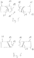
- the contour 21 of the inlay 19 has a concave portion 22. In Fig. 3 this is indicated by a dashed line connecting two points of the contour 21 and which lies outside of the inlay 19. It has been found that the force flow within the bone plate can be improved by means of such concave sections in the contour 21 of the inlay 19.
- the inlay 19 is rounded. It is accepted that the contour 21 of the inlay 19 intersects the direction of the force flow at right angles. However, in such a design it is easier to produce the homogeneous material transition between the material of the inlay 19 and the material of the carrier part 20 which is advantageous for a uniform flow of force.
- Fig. 4 joins the concave portion 22 in the contour 21 of the inlay 19 a widening 25 at. At the ends 23, the inlay 19 runs to a point. Due to the widening 25, the contour 21 of the inlay 19 extends, which has proved advantageous for a uniform flow of force within the bone plate.
- the contour surface is not aligned perpendicular to the plane of the inlay 19, but the inlay 19 is narrower at the lower end and widens towards the top.
- the transition from the bottom 16 to the top 15 is curved, which is advantageous for a uniform flow of force within the bone plate.
- the contour surface is flat and encloses an angle with the vertical. With a flat contour surface, it is easier to create a homogeneous transition between the material of the inlay 19 and the material of the carrier part 20 by laser welding.
Landscapes
- Health & Medical Sciences (AREA)
- Orthopedic Medicine & Surgery (AREA)
- Surgery (AREA)
- Life Sciences & Earth Sciences (AREA)
- Heart & Thoracic Surgery (AREA)
- Nuclear Medicine, Radiotherapy & Molecular Imaging (AREA)
- Engineering & Computer Science (AREA)
- Biomedical Technology (AREA)
- Neurology (AREA)
- Medical Informatics (AREA)
- Molecular Biology (AREA)
- Animal Behavior & Ethology (AREA)
- General Health & Medical Sciences (AREA)
- Public Health (AREA)
- Veterinary Medicine (AREA)
- Surgical Instruments (AREA)
Claims (14)
- Plaque d'ostéosynthèse dotée d'une partie de support (20) et d'un inlay (19) inséré dans la partie de support (20) et assemblé à la partie de support (20), dans laquelle l'inlay (19) se compose d'un matériau plus mou que la partie de support (20) et dans laquelle exactement un trou de passage (14), qui est disposé au milieu dans l'inlay (19), est formé dans l'inlay (19), caractérisée en ce que l'inlay (19) présente une plus grande extension dans une direction longitudinale que dans une direction transversale et en ce que la distance du trou de passage (14) à l'extrémité (23) de l'inlay (19) située le plus près en direction longitudinale est plus grande que la distance du trou de passage (14) au bord (24) de l'inlay (19) en direction transversale.
- Plaque d'ostéosynthèse selon la revendication 1, caractérisée en ce que le contour (21) de l'inlay (19) présente une partie concave (22).
- Plaque d'ostéosynthèse selon la revendication 1 ou 2, caractérisée en ce que la largeur de l'inlay (19) diminue de façon continue à partir du trou de passage (14) en direction de l'extrémité située le plus près (23) en direction longitudinale.
- Plaque d'ostéosynthèse selon la revendication 1 ou 2, caractérisée en ce que l'inlay (19) présente un élargissement (25) entre le trou de passage (14) et l'extrémité située le plus près (23) en direction longitudinale.
- Plaque d'ostéosynthèse selon l'une quelconque des revendications 1 à 4, caractérisée en ce que l'extrémité (23) de l'inlay (19) située le plus près en direction longitudinale se termine en pointe.
- Plaque d'ostéosynthèse selon l'une quelconque des revendications 1 à 4, caractérisée en ce que l'extrémité (23) de l'inlay (19) située le plus près en direction longitudinale est arrondie.
- Plaque d'ostéosynthèse selon l'une quelconque des revendications 1 à 6, caractérisée en ce qu'une face de contour de l'inlay (19) est bombée par rapport à la direction orientée perpendiculairement au plan de l'inlay (19) ou forme un angle avec cette direction.
- Plaque d'ostéosynthèse selon l'une quelconque des revendications 1 à 7, caractérisée en ce que l'inlay (19) est fabriqué en tôle laminée et en ce que la direction de laminage est parallèle à la direction longitudinale de l'inlay (19).
- Plaque d'ostéosynthèse selon l'une quelconque des revendications 1 à 8, caractérisée en ce que l'inlay (19) se compose de titane pur de qualité 0 ou de qualité 1.
- Plaque d'ostéosynthèse selon l'une quelconque des revendications 1 à 9, caractérisée en ce que la partie de support (20) se compose de titane pur de qualité 4 ou d'un alliage de titane.
- Plaque d'ostéosynthèse selon l'une quelconque des revendications 1 à 10, caractérisée en ce que la plaque d'ostéosynthèse présente un second trou de passage (14) et en ce que la direction longitudinale de l'inlay (19) est orientée parallèlement à la ligne de jonction entre le trou de passage (14) et le second trou de passage (14).
- Système composé d'une plaque d'ostéosynthèse selon l'une quelconque des revendications 1 à 11 et d'une vis à os (31), dans lequel la vis à os (31) présente un filet de tête (30), qui est conçu pour déformer le matériau de l'inlay (19) afin de former un assemblage vissé.
- Procédé de fabrication d'une plaque d'ostéosynthèse dans lequel on prépare une partie de support (20) de la plaque d'ostéosynthèse et un inlay (19), dans lequel l'inlay (19) présente exactement un trou de passage (14), qui est disposé au milieu de l'inlay (19), et se compose d'un matériau plus mou que la partie de support (20) et dans lequel la partie de support (20) est dotée d'un évidement adapté à l'inlay (19), dans lequel l'inlay (19) est inséré, de telle manière qu'une face de contour de l'inlay (19) s'applique en surface sur la partie de support (20), caractérisé en ce que l'on assemble l'inlay (19) à la partie de support (20) le long de la face de contour, dans lequel l'inlay (19) présente une plus grande extension dans une direction longitudinale que dans une direction transversale et dans lequel la distance du trou de passage (14) à l'extrémité (23) de l'inlay (19) située le plus près en direction longitudinale est plus grande que la distance du trou de passage (14) au bord de l'inlay (19) en direction transversale.
- Procédé selon la revendication, caractérisé en ce que l'on assemble l'inlay (19) à la partie de support (20) par soudage au laser.
Priority Applications (2)
| Application Number | Priority Date | Filing Date | Title |
|---|---|---|---|
| EP13167045.7A EP2801330B1 (fr) | 2013-05-08 | 2013-05-08 | Plaque d'ostéosynthèse dotée d'un inlay et procédé de fabrication de la plaque d'ostéosynthèse |
| ES13167045.7T ES2689801T3 (es) | 2013-05-08 | 2013-05-08 | Placa de osteosíntesis con un injerto encastrado y procedimiento para fabricar la placa de osteosíntesis |
Applications Claiming Priority (1)
| Application Number | Priority Date | Filing Date | Title |
|---|---|---|---|
| EP13167045.7A EP2801330B1 (fr) | 2013-05-08 | 2013-05-08 | Plaque d'ostéosynthèse dotée d'un inlay et procédé de fabrication de la plaque d'ostéosynthèse |
Publications (2)
| Publication Number | Publication Date |
|---|---|
| EP2801330A1 EP2801330A1 (fr) | 2014-11-12 |
| EP2801330B1 true EP2801330B1 (fr) | 2018-07-04 |
Family
ID=48366192
Family Applications (1)
| Application Number | Title | Priority Date | Filing Date |
|---|---|---|---|
| EP13167045.7A Not-in-force EP2801330B1 (fr) | 2013-05-08 | 2013-05-08 | Plaque d'ostéosynthèse dotée d'un inlay et procédé de fabrication de la plaque d'ostéosynthèse |
Country Status (2)
| Country | Link |
|---|---|
| EP (1) | EP2801330B1 (fr) |
| ES (1) | ES2689801T3 (fr) |
Families Citing this family (2)
| Publication number | Priority date | Publication date | Assignee | Title |
|---|---|---|---|---|
| ES2768851T3 (es) * | 2016-02-19 | 2020-06-23 | 41Medical Ag | Dispositivo de fijación de hueso |
| EP3501437A1 (fr) | 2017-12-20 | 2019-06-26 | Dietmar Wolter | Plaque d'ostéosynthèse et procédé de fabrication d'une plaque d'ostéosynthèse |
Family Cites Families (5)
| Publication number | Priority date | Publication date | Assignee | Title |
|---|---|---|---|---|
| DE19629011C2 (de) | 1996-07-18 | 2001-08-23 | Dietmar Wolter | Hilfsmittel für die Osteosynthese |
| US6955677B2 (en) * | 2002-10-15 | 2005-10-18 | The University Of North Carolina At Chapel Hill | Multi-angular fastening apparatus and method for surgical bone screw/plate systems |
| ES2522925T3 (es) * | 2009-04-08 | 2014-11-19 | Stryker Trauma Sa | Placa ósea híbrida |
| SM201100002B (it) * | 2011-01-10 | 2013-09-06 | Hit Medica Spa | Dispositivo di osteosintesi e procedimento per la sua realizzazione |
| US20130053847A1 (en) * | 2011-08-31 | 2013-02-28 | Mark Siravo | Implant Devices Constructed with Metallic and Polymeric Components |
-
2013
- 2013-05-08 EP EP13167045.7A patent/EP2801330B1/fr not_active Not-in-force
- 2013-05-08 ES ES13167045.7T patent/ES2689801T3/es active Active
Non-Patent Citations (1)
| Title |
|---|
| None * |
Also Published As
| Publication number | Publication date |
|---|---|
| EP2801330A1 (fr) | 2014-11-12 |
| ES2689801T3 (es) | 2018-11-15 |
Similar Documents
| Publication | Publication Date | Title |
|---|---|---|
| EP2416720B1 (fr) | Dispositif de fixation à stabilité angulaire et de compression d'un foyer de fracture ou d'une ostéotomie sur un os | |
| EP1613227B1 (fr) | Plaque d'osteosynthese destinee au traitement operatoire de fractures osseuses | |
| EP2892451B1 (fr) | Implant de la ceinture pelvienne | |
| EP1143867B1 (fr) | Systeme de fixation pour os | |
| EP0053999B1 (fr) | Dispositif d'ostéosynthèse et calibre de perçage approprié | |
| EP1608278B1 (fr) | Logement pour un element de blocage et element de blocage | |
| EP2584983B1 (fr) | Plaque osseuse et système de fixation avec plaque osseuse | |
| EP3081180B1 (fr) | Systeme de fixation pour os | |
| EP2741701A1 (fr) | Système composé d'une plaque d'ostéosynthèse et d'une vis d'ostéosynthèse | |
| EP2844169B1 (fr) | Système à plaque osseuse pour l'ostéosynthèse | |
| WO2012156453A1 (fr) | Plaque ostéologique | |
| DE19603285A1 (de) | Intramedullärer Nagel | |
| DE102005004841B4 (de) | Osteosyntheseplatte mit einer Vielzahl von Bohrungen zur Aufnahme von Knochenschrauben | |
| EP3261566B1 (fr) | Plaque d'ostéosynthèse et kit chirurgical pour la fixation de fragments osseux | |
| EP2476388B1 (fr) | Plaque d'ostéosynthèse, notamment plaque radiale ou plaque Ulnar, destinée à la stabilisation de fractures d'os | |
| EP1712197A1 (fr) | Plaque d'ostéosynthèse | |
| EP2801330B1 (fr) | Plaque d'ostéosynthèse dotée d'un inlay et procédé de fabrication de la plaque d'ostéosynthèse | |
| DE102015102629B4 (de) | Knochenplatte | |
| EP2755584B1 (fr) | Plaque de cuisson | |
| DE102005001438B3 (de) | Set zur Erstellung eines Osteosyntheseimplantates | |
| EP3157449A1 (fr) | Vis pédiculaire avec outil de vissage | |
| EP2810610B1 (fr) | Plaque de cuisson | |
| DE102019104546A1 (de) | Implantat aus einem bioresorbierbarem Material sowie Verfahren zu dessen Herstellung | |
| EP3501437A1 (fr) | Plaque d'ostéosynthèse et procédé de fabrication d'une plaque d'ostéosynthèse | |
| AT507501B1 (de) | Knochenschraube |
Legal Events
| Date | Code | Title | Description |
|---|---|---|---|
| PUAI | Public reference made under article 153(3) epc to a published international application that has entered the european phase |
Free format text: ORIGINAL CODE: 0009012 |
|
| 17P | Request for examination filed |
Effective date: 20130508 |
|
| AK | Designated contracting states |
Kind code of ref document: A1 Designated state(s): AL AT BE BG CH CY CZ DE DK EE ES FI FR GB GR HR HU IE IS IT LI LT LU LV MC MK MT NL NO PL PT RO RS SE SI SK SM TR |
|
| AX | Request for extension of the european patent |
Extension state: BA ME |
|
| R17P | Request for examination filed (corrected) |
Effective date: 20150512 |
|
| RBV | Designated contracting states (corrected) |
Designated state(s): AL AT BE BG CH CY CZ DE DK EE ES FI FR GB GR HR HU IE IS IT LI LT LU LV MC MK MT NL NO PL PT RO RS SE SI SK SM TR |
|
| GRAP | Despatch of communication of intention to grant a patent |
Free format text: ORIGINAL CODE: EPIDOSNIGR1 |
|
| STAA | Information on the status of an ep patent application or granted ep patent |
Free format text: STATUS: GRANT OF PATENT IS INTENDED |
|
| INTG | Intention to grant announced |
Effective date: 20180104 |
|
| GRAS | Grant fee paid |
Free format text: ORIGINAL CODE: EPIDOSNIGR3 |
|
| GRAA | (expected) grant |
Free format text: ORIGINAL CODE: 0009210 |
|
| STAA | Information on the status of an ep patent application or granted ep patent |
Free format text: STATUS: THE PATENT HAS BEEN GRANTED |
|
| AK | Designated contracting states |
Kind code of ref document: B1 Designated state(s): AL AT BE BG CH CY CZ DE DK EE ES FI FR GB GR HR HU IE IS IT LI LT LU LV MC MK MT NL NO PL PT RO RS SE SI SK SM TR |
|
| REG | Reference to a national code |
Ref country code: GB Ref legal event code: FG4D Free format text: NOT ENGLISH |
|
| REG | Reference to a national code |
Ref country code: CH Ref legal event code: EP |
|
| REG | Reference to a national code |
Ref country code: AT Ref legal event code: REF Ref document number: 1013674 Country of ref document: AT Kind code of ref document: T Effective date: 20180715 |
|
| REG | Reference to a national code |
Ref country code: IE Ref legal event code: FG4D Free format text: LANGUAGE OF EP DOCUMENT: GERMAN |
|
| REG | Reference to a national code |
Ref country code: DE Ref legal event code: R096 Ref document number: 502013010523 Country of ref document: DE |
|
| REG | Reference to a national code |
Ref country code: NL Ref legal event code: MP Effective date: 20180704 |
|
| REG | Reference to a national code |
Ref country code: ES Ref legal event code: FG2A Ref document number: 2689801 Country of ref document: ES Kind code of ref document: T3 Effective date: 20181115 |
|
| REG | Reference to a national code |
Ref country code: LT Ref legal event code: MG4D |
|
| PG25 | Lapsed in a contracting state [announced via postgrant information from national office to epo] |
Ref country code: NL Free format text: LAPSE BECAUSE OF FAILURE TO SUBMIT A TRANSLATION OF THE DESCRIPTION OR TO PAY THE FEE WITHIN THE PRESCRIBED TIME-LIMIT Effective date: 20180704 |
|
| PG25 | Lapsed in a contracting state [announced via postgrant information from national office to epo] |
Ref country code: FI Free format text: LAPSE BECAUSE OF FAILURE TO SUBMIT A TRANSLATION OF THE DESCRIPTION OR TO PAY THE FEE WITHIN THE PRESCRIBED TIME-LIMIT Effective date: 20180704 Ref country code: LT Free format text: LAPSE BECAUSE OF FAILURE TO SUBMIT A TRANSLATION OF THE DESCRIPTION OR TO PAY THE FEE WITHIN THE PRESCRIBED TIME-LIMIT Effective date: 20180704 Ref country code: IS Free format text: LAPSE BECAUSE OF FAILURE TO SUBMIT A TRANSLATION OF THE DESCRIPTION OR TO PAY THE FEE WITHIN THE PRESCRIBED TIME-LIMIT Effective date: 20181104 Ref country code: RS Free format text: LAPSE BECAUSE OF FAILURE TO SUBMIT A TRANSLATION OF THE DESCRIPTION OR TO PAY THE FEE WITHIN THE PRESCRIBED TIME-LIMIT Effective date: 20180704 Ref country code: CZ Free format text: LAPSE BECAUSE OF FAILURE TO SUBMIT A TRANSLATION OF THE DESCRIPTION OR TO PAY THE FEE WITHIN THE PRESCRIBED TIME-LIMIT Effective date: 20180704 Ref country code: GR Free format text: LAPSE BECAUSE OF FAILURE TO SUBMIT A TRANSLATION OF THE DESCRIPTION OR TO PAY THE FEE WITHIN THE PRESCRIBED TIME-LIMIT Effective date: 20181005 Ref country code: NO Free format text: LAPSE BECAUSE OF FAILURE TO SUBMIT A TRANSLATION OF THE DESCRIPTION OR TO PAY THE FEE WITHIN THE PRESCRIBED TIME-LIMIT Effective date: 20181004 Ref country code: BG Free format text: LAPSE BECAUSE OF FAILURE TO SUBMIT A TRANSLATION OF THE DESCRIPTION OR TO PAY THE FEE WITHIN THE PRESCRIBED TIME-LIMIT Effective date: 20181004 Ref country code: PL Free format text: LAPSE BECAUSE OF FAILURE TO SUBMIT A TRANSLATION OF THE DESCRIPTION OR TO PAY THE FEE WITHIN THE PRESCRIBED TIME-LIMIT Effective date: 20180704 Ref country code: SE Free format text: LAPSE BECAUSE OF FAILURE TO SUBMIT A TRANSLATION OF THE DESCRIPTION OR TO PAY THE FEE WITHIN THE PRESCRIBED TIME-LIMIT Effective date: 20180704 |
|
| PG25 | Lapsed in a contracting state [announced via postgrant information from national office to epo] |
Ref country code: AL Free format text: LAPSE BECAUSE OF FAILURE TO SUBMIT A TRANSLATION OF THE DESCRIPTION OR TO PAY THE FEE WITHIN THE PRESCRIBED TIME-LIMIT Effective date: 20180704 Ref country code: LV Free format text: LAPSE BECAUSE OF FAILURE TO SUBMIT A TRANSLATION OF THE DESCRIPTION OR TO PAY THE FEE WITHIN THE PRESCRIBED TIME-LIMIT Effective date: 20180704 Ref country code: HR Free format text: LAPSE BECAUSE OF FAILURE TO SUBMIT A TRANSLATION OF THE DESCRIPTION OR TO PAY THE FEE WITHIN THE PRESCRIBED TIME-LIMIT Effective date: 20180704 |
|
| REG | Reference to a national code |
Ref country code: DE Ref legal event code: R097 Ref document number: 502013010523 Country of ref document: DE |
|
| PG25 | Lapsed in a contracting state [announced via postgrant information from national office to epo] |
Ref country code: EE Free format text: LAPSE BECAUSE OF FAILURE TO SUBMIT A TRANSLATION OF THE DESCRIPTION OR TO PAY THE FEE WITHIN THE PRESCRIBED TIME-LIMIT Effective date: 20180704 Ref country code: RO Free format text: LAPSE BECAUSE OF FAILURE TO SUBMIT A TRANSLATION OF THE DESCRIPTION OR TO PAY THE FEE WITHIN THE PRESCRIBED TIME-LIMIT Effective date: 20180704 Ref country code: IT Free format text: LAPSE BECAUSE OF FAILURE TO SUBMIT A TRANSLATION OF THE DESCRIPTION OR TO PAY THE FEE WITHIN THE PRESCRIBED TIME-LIMIT Effective date: 20180704 |
|
| PLBE | No opposition filed within time limit |
Free format text: ORIGINAL CODE: 0009261 |
|
| STAA | Information on the status of an ep patent application or granted ep patent |
Free format text: STATUS: NO OPPOSITION FILED WITHIN TIME LIMIT |
|
| PG25 | Lapsed in a contracting state [announced via postgrant information from national office to epo] |
Ref country code: DK Free format text: LAPSE BECAUSE OF FAILURE TO SUBMIT A TRANSLATION OF THE DESCRIPTION OR TO PAY THE FEE WITHIN THE PRESCRIBED TIME-LIMIT Effective date: 20180704 Ref country code: SM Free format text: LAPSE BECAUSE OF FAILURE TO SUBMIT A TRANSLATION OF THE DESCRIPTION OR TO PAY THE FEE WITHIN THE PRESCRIBED TIME-LIMIT Effective date: 20180704 Ref country code: SK Free format text: LAPSE BECAUSE OF FAILURE TO SUBMIT A TRANSLATION OF THE DESCRIPTION OR TO PAY THE FEE WITHIN THE PRESCRIBED TIME-LIMIT Effective date: 20180704 |
|
| 26N | No opposition filed |
Effective date: 20190405 |
|
| PG25 | Lapsed in a contracting state [announced via postgrant information from national office to epo] |
Ref country code: SI Free format text: LAPSE BECAUSE OF FAILURE TO SUBMIT A TRANSLATION OF THE DESCRIPTION OR TO PAY THE FEE WITHIN THE PRESCRIBED TIME-LIMIT Effective date: 20180704 |
|
| REG | Reference to a national code |
Ref country code: CH Ref legal event code: PL |
|
| PG25 | Lapsed in a contracting state [announced via postgrant information from national office to epo] |
Ref country code: CH Free format text: LAPSE BECAUSE OF NON-PAYMENT OF DUE FEES Effective date: 20190531 Ref country code: LI Free format text: LAPSE BECAUSE OF NON-PAYMENT OF DUE FEES Effective date: 20190531 Ref country code: MC Free format text: LAPSE BECAUSE OF FAILURE TO SUBMIT A TRANSLATION OF THE DESCRIPTION OR TO PAY THE FEE WITHIN THE PRESCRIBED TIME-LIMIT Effective date: 20180704 |
|
| REG | Reference to a national code |
Ref country code: BE Ref legal event code: MM Effective date: 20190531 |
|
| PG25 | Lapsed in a contracting state [announced via postgrant information from national office to epo] |
Ref country code: LU Free format text: LAPSE BECAUSE OF NON-PAYMENT OF DUE FEES Effective date: 20190508 |
|
| PG25 | Lapsed in a contracting state [announced via postgrant information from national office to epo] |
Ref country code: TR Free format text: LAPSE BECAUSE OF FAILURE TO SUBMIT A TRANSLATION OF THE DESCRIPTION OR TO PAY THE FEE WITHIN THE PRESCRIBED TIME-LIMIT Effective date: 20180704 |
|
| PG25 | Lapsed in a contracting state [announced via postgrant information from national office to epo] |
Ref country code: IE Free format text: LAPSE BECAUSE OF NON-PAYMENT OF DUE FEES Effective date: 20190508 |
|
| PG25 | Lapsed in a contracting state [announced via postgrant information from national office to epo] |
Ref country code: BE Free format text: LAPSE BECAUSE OF NON-PAYMENT OF DUE FEES Effective date: 20190531 |
|
| PG25 | Lapsed in a contracting state [announced via postgrant information from national office to epo] |
Ref country code: PT Free format text: LAPSE BECAUSE OF FAILURE TO SUBMIT A TRANSLATION OF THE DESCRIPTION OR TO PAY THE FEE WITHIN THE PRESCRIBED TIME-LIMIT Effective date: 20181105 |
|
| PGFP | Annual fee paid to national office [announced via postgrant information from national office to epo] |
Ref country code: FR Payment date: 20200519 Year of fee payment: 8 Ref country code: ES Payment date: 20200618 Year of fee payment: 8 |
|
| REG | Reference to a national code |
Ref country code: AT Ref legal event code: MM01 Ref document number: 1013674 Country of ref document: AT Kind code of ref document: T Effective date: 20190508 |
|
| PGFP | Annual fee paid to national office [announced via postgrant information from national office to epo] |
Ref country code: GB Payment date: 20200522 Year of fee payment: 8 |
|
| PGFP | Annual fee paid to national office [announced via postgrant information from national office to epo] |
Ref country code: DE Payment date: 20200727 Year of fee payment: 8 |
|
| PG25 | Lapsed in a contracting state [announced via postgrant information from national office to epo] |
Ref country code: AT Free format text: LAPSE BECAUSE OF NON-PAYMENT OF DUE FEES Effective date: 20190508 |
|
| PG25 | Lapsed in a contracting state [announced via postgrant information from national office to epo] |
Ref country code: CY Free format text: LAPSE BECAUSE OF FAILURE TO SUBMIT A TRANSLATION OF THE DESCRIPTION OR TO PAY THE FEE WITHIN THE PRESCRIBED TIME-LIMIT Effective date: 20180704 |
|
| PG25 | Lapsed in a contracting state [announced via postgrant information from national office to epo] |
Ref country code: HU Free format text: LAPSE BECAUSE OF FAILURE TO SUBMIT A TRANSLATION OF THE DESCRIPTION OR TO PAY THE FEE WITHIN THE PRESCRIBED TIME-LIMIT; INVALID AB INITIO Effective date: 20130508 Ref country code: MT Free format text: LAPSE BECAUSE OF FAILURE TO SUBMIT A TRANSLATION OF THE DESCRIPTION OR TO PAY THE FEE WITHIN THE PRESCRIBED TIME-LIMIT Effective date: 20180704 |
|
| REG | Reference to a national code |
Ref country code: DE Ref legal event code: R119 Ref document number: 502013010523 Country of ref document: DE |
|
| GBPC | Gb: european patent ceased through non-payment of renewal fee |
Effective date: 20210508 |
|
| PG25 | Lapsed in a contracting state [announced via postgrant information from national office to epo] |
Ref country code: GB Free format text: LAPSE BECAUSE OF NON-PAYMENT OF DUE FEES Effective date: 20210508 Ref country code: DE Free format text: LAPSE BECAUSE OF NON-PAYMENT OF DUE FEES Effective date: 20211201 |
|
| PG25 | Lapsed in a contracting state [announced via postgrant information from national office to epo] |
Ref country code: FR Free format text: LAPSE BECAUSE OF NON-PAYMENT OF DUE FEES Effective date: 20210531 |
|
| PG25 | Lapsed in a contracting state [announced via postgrant information from national office to epo] |
Ref country code: MK Free format text: LAPSE BECAUSE OF FAILURE TO SUBMIT A TRANSLATION OF THE DESCRIPTION OR TO PAY THE FEE WITHIN THE PRESCRIBED TIME-LIMIT Effective date: 20180704 |
|
| REG | Reference to a national code |
Ref country code: ES Ref legal event code: FD2A Effective date: 20220804 |
|
| PG25 | Lapsed in a contracting state [announced via postgrant information from national office to epo] |
Ref country code: ES Free format text: LAPSE BECAUSE OF NON-PAYMENT OF DUE FEES Effective date: 20210509 |