EP3501437A1 - Plaque d'ostéosynthèse et procédé de fabrication d'une plaque d'ostéosynthèse - Google Patents
Plaque d'ostéosynthèse et procédé de fabrication d'une plaque d'ostéosynthèse Download PDFInfo
- Publication number
- EP3501437A1 EP3501437A1 EP17209169.6A EP17209169A EP3501437A1 EP 3501437 A1 EP3501437 A1 EP 3501437A1 EP 17209169 A EP17209169 A EP 17209169A EP 3501437 A1 EP3501437 A1 EP 3501437A1
- Authority
- EP
- European Patent Office
- Prior art keywords
- inlay
- bone plate
- supporting structure
- bone
- weld
- Prior art date
- Legal status (The legal status is an assumption and is not a legal conclusion. Google has not performed a legal analysis and makes no representation as to the accuracy of the status listed.)
- Withdrawn
Links
- 210000000988 bone and bone Anatomy 0.000 title claims abstract description 136
- 238000004519 manufacturing process Methods 0.000 title claims abstract description 9
- 239000000463 material Substances 0.000 claims abstract description 76
- 230000035515 penetration Effects 0.000 claims abstract description 4
- 238000000034 method Methods 0.000 claims description 16
- 230000007704 transition Effects 0.000 claims description 16
- 238000003466 welding Methods 0.000 claims description 9
- RTAQQCXQSZGOHL-UHFFFAOYSA-N Titanium Chemical compound [Ti] RTAQQCXQSZGOHL-UHFFFAOYSA-N 0.000 description 13
- 239000010936 titanium Substances 0.000 description 13
- 229910052719 titanium Inorganic materials 0.000 description 13
- 229910001069 Ti alloy Inorganic materials 0.000 description 4
- QVGXLLKOCUKJST-UHFFFAOYSA-N atomic oxygen Chemical compound [O] QVGXLLKOCUKJST-UHFFFAOYSA-N 0.000 description 4
- 229910052760 oxygen Inorganic materials 0.000 description 4
- 239000001301 oxygen Substances 0.000 description 4
- 239000007787 solid Substances 0.000 description 3
- 239000012634 fragment Substances 0.000 description 2
- 229910001257 Nb alloy Inorganic materials 0.000 description 1
- 239000000109 continuous material Substances 0.000 description 1
- 230000000694 effects Effects 0.000 description 1
- 230000017525 heat dissipation Effects 0.000 description 1
- 230000001771 impaired effect Effects 0.000 description 1
- 239000012535 impurity Substances 0.000 description 1
- 238000003780 insertion Methods 0.000 description 1
- 230000037431 insertion Effects 0.000 description 1
- 238000003754 machining Methods 0.000 description 1
- 238000003801 milling Methods 0.000 description 1
- RJSRQTFBFAJJIL-UHFFFAOYSA-N niobium titanium Chemical compound [Ti].[Nb] RJSRQTFBFAJJIL-UHFFFAOYSA-N 0.000 description 1
- 230000000149 penetrating effect Effects 0.000 description 1
- 230000000717 retained effect Effects 0.000 description 1
- 238000001356 surgical procedure Methods 0.000 description 1
- 210000000689 upper leg Anatomy 0.000 description 1
Images


Classifications
-
- A—HUMAN NECESSITIES
- A61—MEDICAL OR VETERINARY SCIENCE; HYGIENE
- A61B—DIAGNOSIS; SURGERY; IDENTIFICATION
- A61B17/00—Surgical instruments, devices or methods
- A61B17/56—Surgical instruments or methods for treatment of bones or joints; Devices specially adapted therefor
- A61B17/58—Surgical instruments or methods for treatment of bones or joints; Devices specially adapted therefor for osteosynthesis, e.g. bone plates, screws or setting implements
- A61B17/68—Internal fixation devices, including fasteners and spinal fixators, even if a part thereof projects from the skin
- A61B17/80—Cortical plates, i.e. bone plates; Instruments for holding or positioning cortical plates, or for compressing bones attached to cortical plates
- A61B17/8052—Cortical plates, i.e. bone plates; Instruments for holding or positioning cortical plates, or for compressing bones attached to cortical plates immobilised relative to screws by interlocking form of the heads and plate holes, e.g. conical or threaded
- A61B17/8057—Cortical plates, i.e. bone plates; Instruments for holding or positioning cortical plates, or for compressing bones attached to cortical plates immobilised relative to screws by interlocking form of the heads and plate holes, e.g. conical or threaded the interlocking form comprising a thread
-
- A—HUMAN NECESSITIES
- A61—MEDICAL OR VETERINARY SCIENCE; HYGIENE
- A61B—DIAGNOSIS; SURGERY; IDENTIFICATION
- A61B17/00—Surgical instruments, devices or methods
- A61B17/56—Surgical instruments or methods for treatment of bones or joints; Devices specially adapted therefor
- A61B17/58—Surgical instruments or methods for treatment of bones or joints; Devices specially adapted therefor for osteosynthesis, e.g. bone plates, screws or setting implements
- A61B17/68—Internal fixation devices, including fasteners and spinal fixators, even if a part thereof projects from the skin
- A61B17/80—Cortical plates, i.e. bone plates; Instruments for holding or positioning cortical plates, or for compressing bones attached to cortical plates
-
- A—HUMAN NECESSITIES
- A61—MEDICAL OR VETERINARY SCIENCE; HYGIENE
- A61B—DIAGNOSIS; SURGERY; IDENTIFICATION
- A61B17/00—Surgical instruments, devices or methods
- A61B17/56—Surgical instruments or methods for treatment of bones or joints; Devices specially adapted therefor
- A61B17/58—Surgical instruments or methods for treatment of bones or joints; Devices specially adapted therefor for osteosynthesis, e.g. bone plates, screws or setting implements
- A61B17/68—Internal fixation devices, including fasteners and spinal fixators, even if a part thereof projects from the skin
- A61B17/84—Fasteners therefor or fasteners being internal fixation devices
- A61B17/86—Pins or screws or threaded wires; nuts therefor
- A61B17/8605—Heads, i.e. proximal ends projecting from bone
Definitions
- the invention relates to a bone plate and a method for producing a bone plate.
- Bone plates can be joined to a bone as part of a surgical operation. They are used, for example, to stabilize a bone after a fracture. To do this, the bone plate is positioned so that it extends beyond the fracture site, and then attached to the bone fragments. The fracture is thereby immobilized and the bone can heal.
- the bone plate may also serve other purposes and, for example, be an element of an endoprosthesis to be connected to a bone.
- a bone screw can be used, the shaft and the head are provided with a thread.
- the shaft is passed through a through hole of the bone plate and screwed into the bone material until the head of the screw enters the through hole of the bone plate.
- the thread on the head of the bone screw engages with the material of the bone plate surrounding the through hole, so that a threaded connection is formed by forming the material of the bone plate.
- the angle at which the threaded connection is made can be freely selected within a predetermined range. The connection is thus multidirectionally stable in angle, so that the surgeon the Einfwinkel during surgery, while still creating a stable angle connection between the bone screw and the bone plate.
- the bone plate in the area of the through hole consists of a material that can be well formed. It is known to use an inlay in a supporting structure of the bone plate for this purpose.
- Such an inlay can for example be connected to the supporting structure of the bone plate by welding, DE 196 29 011 A1 .
- WO 2010/115458 A1 When welding, heat is introduced into the material, which can result in undesirable effects on the material structure.
- the invention is based on the object to present a bone plate and a method for producing a bone plate, in which the probability of undesirable changes in the internal structure of the bone plate is reduced. Based on the cited prior art, the object is achieved with the features of the independent claims. Advantageous embodiments are specified in the subclaims.
- an inlay is inserted into a recess of a supporting structure, so that a lateral surface of the inlay bears against an inner circumferential surface of the recess.
- the inlay and the supporting structure are connected to one another by a weld seam, wherein the penetration depth of the weld seam in one embodiment of the invention is smaller than the material thickness in the region of the weld seam.
- the weld extends only over part of the material thickness, the heat input can be reduced, which acts on the bone plate when creating the weld. Due to the reduced heat input into the material of the bone plate, a change in the material structure can be avoided. In particular, in the region of the inlay in which the screw head engages, a material structure of the inlay designed for good deformability can be retained. The material of the inlay can be deformed with little effort by screwing in the bone screw.
- the supporting structure may have a recess with an inner circumferential surface matching the lateral surface of the inlay.
- the lateral surface of the inlay and the inner circumferential surface of the supporting structure can lie flat on one another along a contact surface.
- the material thickness in the region of the weld seam corresponds to the height of the contact surface, that is to say the surface over which the lateral surface of the inlay and the inner lateral surface of the supporting structure lie flat on one another.
- the height is the direction which extends perpendicular to the circumferential direction of the lateral surface or the inner lateral surface.
- the weld extends only over part of the material thickness, there is a transition region between the inlay and the supporting structure on the side opposite the weld, where the two parts lie against each other but are not welded together.
- a mechanical processing of the transition region can take place.
- a possible gap between the inlay and the supporting structure can be closed, for example by the transition area is milled over. It can be created a closed surface, so that the penetration of impurities is prevented.
- the mechanical processing can be carried out in such a way that material is removed from the inlay and / or from the supporting structure in the transition region, so that the material thickness in the region of the contact surface is reduced.
- an inlay can be used which is already provided with a through-hole prior to insertion into the supporting structure.
- subsequent processing can be dispensed with if a material lip projecting inwards from the hole wall is already formed in the through hole. It is also possible to subsequently produce such a material lip in a prefabricated through hole.
- an inlay can be inserted into the supporting structure, which does not yet have a through hole at this time. If the inlay at the time the weld seams is generated, forms a solid without a through hole, the heat generated by the welding can be better distributed, so that the risk of structural changes in the material continues to decrease.
- a through-hole can be created in the inlay.
- the through hole may be formed so that a material lip protrudes inward from the hole wall.
- the bone plate may have a bottom facing the bone and an upper side burned by the bone when the bone plate is properly connected to a bone.
- a through hole formed in the bone plate may extend between the bottom and the top.
- the method according to the invention can be carried out such that the weld seam is executed from the underside of the bone plate.
- the transition region, where the inlay and the supporting structure abut each other without being welded together, may be oriented toward the top of the bone plate.
- the weld can be produced for example by laser welding.
- the lateral surface of the inlay can be cylindrical or conical. It is also possible that the cylindrical area and / or the conical area does not extend over the entire material thickness, but only over a height portion of the material thickness.
- the inlay can have a first height section, in which the lateral surface is cylindrical and has a second height section, in FIG the lateral surface is cone-shaped. The cone-shaped height portion may taper toward the cylindrical height portion.
- the invention also encompasses lateral surfaces which are not rotationally symmetrical.
- the wider portion of the cone may face the bottom of the bone plate and the narrower portion of the cone may face the top of the bone plate.
- the difference between the largest diameter of the cone and the smallest diameter of the cone may be between 0.01 mm and 0.1 mm, preferably between 0.02 mm and 0.05 mm.
- a stop defining the correct position can be used.
- the abutment may be a stop within the bone plate, as may arise, for example, from the fact that a conical outer surface of an inlay rests against a conical surface of the supporting structure. Also possible is a stop outside the bone plate.
- the combination of the supporting structure and the inlay can then be placed on a stop, so that the underside is easily accessible for producing the weld.
- the inlay inserted into the supporting structure can have the same thickness as the supporting structure.
- the contact area between the inlay and the supporting structure extends over the entire thickness of the inlay.
- the inlay can flush the top and bottom with the supporting structure. It is also possible that the contact surface extends only over part of the thickness of the inlay, for example over at least 50%, preferably over at least 70%, of the thickness of the inlay.
- the thickness refers to the distance between the top and the bottom of the bone plate in the area concerned.
- the inlay protrudes at the bottom against the supporting structure, whereby the surface of the inlay available for heat dissipation can be increased.
- the supporting structure in the vicinity of the inlay exerts a reduced pressure on the bone material, so that the supply of the bone is impaired to a lesser extent.
- the inlay can be flush with the supporting structure.
- the thickness of the inlay is less than the thickness of the supporting structure.
- the inlay may include a lip of material protruding toward the center of the through-hole.
- the material lip may extend in the circumferential direction of the through hole.
- the material lip may extend over part of the circumference or over the entire circumference.
- the lip of material may form the area of the inlay that is reshaped by screwing in the bone screw.
- the material lip may be located within one half of the inlay. The other 50% of the thickness of the inlay are then free of the material lip.
- the material lip is arranged in a third adjacent to the surface. A section of two thirds adjoining the other surface is therefore free of the material lip.
- the material lip may be disposed in a height portion of the inlay that is less than 50%, preferably less than 30%, of the thickness of the inlay.
- the material lip can be arranged in a height section of the inlay which is adjacent to the underside of the bone plate. Above the material lip there then remains space within which the head of the bone screw can be received.
- the force required for forming the inlay and for producing the threaded connection can be kept low. A reduction of this expenditure of force is of particular interest in larger bone plates in which high forces act.
- the bone screws and bone plate are then sized larger and more material of the inlay is reshaped to achieve a sufficiently stable threaded connection between the head of the bone screw and the bone plate.
- the invention can be used in particular for thicker bone plates.
- the thickness of the bone plate may be greater than 2 mm and in particular between 3 mm and 5 mm.
- the thickness of the bone plate is the distance between the top and bottom, which the supporting structure has in the region of the transition to the inlay.
- the bone plates according to the invention may be intended for a large bones of the human body, because these bone plates may be exposed to great leverage. Bone plates for this application have a greater thickness than other bone plates.
- the bone plate may be intended for a femur.
- the weld may extend from a surface of the bone plate into the depth of the material.
- the weld preferably extends over not more than 80%, more preferably not more than 70%, more preferably not more than 60% of the height of the contact surface.
- the weld can penetrate by 1 mm to 3 mm, preferably by 1.5 mm to 2.5 mm in the material of the bone plate.
- the material of the inlay may be softer than the material of the supporting structure. Titanium materials are suitable for the production of the bone plate according to the invention.
- unalloyed titanium pure titanium
- the hardness depends on the oxygen content. The higher the oxygen content the greater the hardness.
- the inlay can be made of pure titanium of low hardness.
- pure titanium grade 0 or grade 1 may be used, wherein the oxygen content may be, for example, less than 0.2%, preferably less than 0.1%.
- the supporting structure of the bone plate can be made of pure titanium of greater hardness.
- the supporting structure may consist of grade 4 pure titanium.
- the oxygen content of the pure titanium may for example be between 0.3% and 0.4%.
- the supporting structure of a Titanium alloy manufacture Titanium alloys usually have a higher hardness than pure titanium. For example, TiAl6V4 or a titanium-niobium alloy is considered.
- the bone plate may have a plurality of through holes. It is possible that a part of the through holes is formed in the supporting structure of the bone plate. In an advantageous embodiment, all the through holes are arranged in the softer inlay material.
- the bone plate may have its own inlay for each through hole. It is also possible that an inlay has a plurality of through holes.
- the invention further relates to a bone plate having a through hole extending between an upper side and a lower side of the bone plate.
- a supporting structure of the bone plate may be formed of a first material.
- the through hole may be formed in an inlay of a second material.
- the supporting structure and the inlay can be connected to each other by a weld.
- a transition region between the load-bearing structure and the inlay opposite the weld can be machined.
- the invention also relates to a system of such a bone plate and a bone screw.
- the head of the screw is threaded (head thread) which is designed to reshape the material of the inlay surrounding the through hole to form a threaded connection.
- the system may include a plurality of bone screws. Since the threaded connection formed only when screwing the bone screw the bone screw can be connected to the bone plate at different angles (angle variable).
- the bone plate can be further developed with further features that are described in the context of the method according to the invention.
- the method can be developed with further features which are described in the context of the bone plate according to the invention.
- the invention also relates to a bone plate which can be produced by the method according to the invention.
- a bone plate 12 according to the invention has according to Fig. 1 six through holes 14 extending from a top 15 of the bone plate to a bottom 16 of the bone plate.
- each through hole 14 there is formed a material lip 17 protruding from the wall of the through hole 14 toward the center of the through hole 14.
- the material lip 17 is a continuous material lip extending without interruption over the entire circumference of the through-hole 14 extends.
- the material lip 17 is arranged in the lower third of the through hole 14, so that above the material lip 17 space for receiving a screw head remains.
- the bone plate is intended to be placed with the bottom 16 on a bone 13, so that the bone plate extends over a break point of the bone away. After the bone is reduced to the correct position, the bone plate is connected to the bone fragments. The bone is then fixed in this position and can heal.
- the bone screws 31 For connecting the bone plate to the bone, bone screws 31 according to the exemplary illustration in FIG Fig. 2 used.
- the bone screws 31 have a shaft 27 which is provided with a bone thread 28, and a screw head 29, whose outer surface has a head thread 30 with a smaller pitch.
- the bone screw is screwed into the bone until the screw head 29 penetrates into the through hole 14.
- the angle which the bone screw encloses with the axis of the through-hole can be freely selected between approximately 0 ° and 15 °.
- the head thread 30 of the bone screw 31 comes into engagement with the material lip 17.
- the material lip 17 is reshaped and a threaded connection is formed between the head 29 of the bone screw 31 and the material lip 17.
- the six through-holes 14 are each formed in an inlay 19.
- the inlay consists of pure titanium grade 1 or grade 0 and thus of a material of comparatively low hardness.
- the inlays are inserted into matching recesses 33 of a supporting structure 20 of the bone plate.
- the supporting structure 20 consists of pure titanium Grade 4 or of the titanium alloy TiAl6V4.
- the bone screw 31 consists of the titanium alloy TiAl6V4 and thus of a harder material than the inlay 19. If the head 29 of the bone screw engages with the material lip 17, the material lip 17 is deformed and a thread connection is created between the head thread 30 and the material lip 17 The bone screw 31 is thereby connected to the bone plate so as to be stable in angular stability.
- a supporting structure 20 of the bone plate is made of pure titanium grade 4 and has for each of the through holes 14 concentric with the later through hole 14 arranged recess 33.
- the recess 33 is formed as a solid body inlay 19 made of pure titanium grade 1, so that the lateral surface 22 of the inlay 19 rests flat on the inner circumferential surface 23 of the recess 33.
- the region in which the lateral surface of the inlay 19 and the inner lateral surface of the recess 33 lie on one another is referred to as a contact surface.
- Both the inlay 19 and the recess 33 have a slight conical shape with a cone angle of about 1 °, which tapers from the bottom 16 to the top 15 out. At the top 15 and bottom 16 of the bone plate 12, the surfaces of the inlay 19 and the supporting structure 20 are flush with each other.
- a weld 21 is produced by laser welding, which penetrates to a depth of about 2.5 mm into the material.
- the bone plate has a material thickness of 3.8 mm, so that the weld 21 extends over slightly more than half the material thickness. The weld 21 thus does not extend over the entire height of the contact surface, but only over a height portion of the contact surface.
- FIG Fig. 5 The state in which the inlay 19, which is in the form of a solid body, is welded in this way to the supporting structure 20, is shown in FIG Fig. 5 shown. This is followed by machining by milling, with which a through hole 14 is produced through the inlay 19. In the lower region of the through hole 14, the material lip 17 remains, which is intended to be later transformed by the head 29 of the bone screw 31.
- transition region 34 With the mechanical processing, in particular, material is removed in the transition region 34, in which the inlay 19 and the supporting structure abut each other, without being welded together.
- the transition region 34 is treated mechanically, so that the seam between the inlay 19 and the supporting structure 20 is closed and results in the transition region 34, a closed surface.
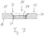
- Fig. 7 an embodiment of the invention is shown in which the mechanical processing engages deeper into the material of the supporting structure 20 and the inlay 19, so that with the mechanical processing into the region of the weld 21 penetrates.
- the closed transition between the inlay 19 and the supporting structure 20 is formed by the weld 21.
Landscapes
- Health & Medical Sciences (AREA)
- Orthopedic Medicine & Surgery (AREA)
- Surgery (AREA)
- Life Sciences & Earth Sciences (AREA)
- Heart & Thoracic Surgery (AREA)
- Nuclear Medicine, Radiotherapy & Molecular Imaging (AREA)
- Engineering & Computer Science (AREA)
- Biomedical Technology (AREA)
- Neurology (AREA)
- Medical Informatics (AREA)
- Molecular Biology (AREA)
- Animal Behavior & Ethology (AREA)
- General Health & Medical Sciences (AREA)
- Public Health (AREA)
- Veterinary Medicine (AREA)
- Surgical Instruments (AREA)
Priority Applications (1)
| Application Number | Priority Date | Filing Date | Title |
|---|---|---|---|
| EP17209169.6A EP3501437A1 (fr) | 2017-12-20 | 2017-12-20 | Plaque d'ostéosynthèse et procédé de fabrication d'une plaque d'ostéosynthèse |
Applications Claiming Priority (1)
| Application Number | Priority Date | Filing Date | Title |
|---|---|---|---|
| EP17209169.6A EP3501437A1 (fr) | 2017-12-20 | 2017-12-20 | Plaque d'ostéosynthèse et procédé de fabrication d'une plaque d'ostéosynthèse |
Publications (1)
| Publication Number | Publication Date |
|---|---|
| EP3501437A1 true EP3501437A1 (fr) | 2019-06-26 |
Family
ID=60702440
Family Applications (1)
| Application Number | Title | Priority Date | Filing Date |
|---|---|---|---|
| EP17209169.6A Withdrawn EP3501437A1 (fr) | 2017-12-20 | 2017-12-20 | Plaque d'ostéosynthèse et procédé de fabrication d'une plaque d'ostéosynthèse |
Country Status (1)
| Country | Link |
|---|---|
| EP (1) | EP3501437A1 (fr) |
Citations (5)
| Publication number | Priority date | Publication date | Assignee | Title |
|---|---|---|---|---|
| DE19629011A1 (de) | 1996-07-18 | 1998-01-22 | Wolter Dietmar Prof Dr Med | Hilfsmittel für die Osteosynthese |
| WO2010115458A1 (fr) | 2009-04-08 | 2010-10-14 | Stryker Trauma Gmbh | Plaque osseuse hybride |
| US20110184415A1 (en) * | 2010-01-26 | 2011-07-28 | Westmark Medical, Llc | Bone screw retention mechanism |
| DE102013005414A1 (de) * | 2013-03-28 | 2014-10-02 | Dietmar Wolter | Osteosynthesesystem für die multidirektionale, winkelstabile Versorgung von Frakturen von Röhrenknochen umfassend einen Marknagel und Knochenschrauben |
| EP2801330A1 (fr) | 2013-05-08 | 2014-11-12 | Dietmar Wolter | Plaque d'ostéosynthèse dotée d'un inlay et procédé de fabrication d'une plaque d'ostéosynthèse |
-
2017
- 2017-12-20 EP EP17209169.6A patent/EP3501437A1/fr not_active Withdrawn
Patent Citations (5)
| Publication number | Priority date | Publication date | Assignee | Title |
|---|---|---|---|---|
| DE19629011A1 (de) | 1996-07-18 | 1998-01-22 | Wolter Dietmar Prof Dr Med | Hilfsmittel für die Osteosynthese |
| WO2010115458A1 (fr) | 2009-04-08 | 2010-10-14 | Stryker Trauma Gmbh | Plaque osseuse hybride |
| US20110184415A1 (en) * | 2010-01-26 | 2011-07-28 | Westmark Medical, Llc | Bone screw retention mechanism |
| DE102013005414A1 (de) * | 2013-03-28 | 2014-10-02 | Dietmar Wolter | Osteosynthesesystem für die multidirektionale, winkelstabile Versorgung von Frakturen von Röhrenknochen umfassend einen Marknagel und Knochenschrauben |
| EP2801330A1 (fr) | 2013-05-08 | 2014-11-12 | Dietmar Wolter | Plaque d'ostéosynthèse dotée d'un inlay et procédé de fabrication d'une plaque d'ostéosynthèse |
Similar Documents
| Publication | Publication Date | Title |
|---|---|---|
| DE69839011T2 (de) | Vorrichtung zum anbringen von skelettplatten | |
| EP2741701B1 (fr) | Système composé d'une plaque osseuse et d'une vis osseuse | |
| EP1608278B1 (fr) | Logement pour un element de blocage et element de blocage | |
| DE69838856T2 (de) | Platte für die vordere Halswirbelsäule mit Fixierungssystem für eine Schraube | |
| EP1476098B1 (fr) | Implant intervertebral | |
| EP2416720B1 (fr) | Dispositif de fixation à stabilité angulaire et de compression d'un foyer de fracture ou d'une ostéotomie sur un os | |
| EP1143867B1 (fr) | Systeme de fixation pour os | |
| EP3081180B1 (fr) | Systeme de fixation pour os | |
| EP2709545A1 (fr) | Plaque ostéologique | |
| EP3267913B1 (fr) | Plaque pour os avec une vis pour os | |
| DE102004009429A1 (de) | Knochenverankerungselement | |
| EP2584983A1 (fr) | Plaque osseuse et système de fixation avec plaque osseuse | |
| DE4343117A1 (de) | Fixationssystem für Knochen | |
| DE102005004841B4 (de) | Osteosyntheseplatte mit einer Vielzahl von Bohrungen zur Aufnahme von Knochenschrauben | |
| DE102015102629B4 (de) | Knochenplatte | |
| EP2755584B1 (fr) | Plaque de cuisson | |
| EP4231946B1 (fr) | Élément fileté optimisé pour l'impression 3d | |
| EP2801330B1 (fr) | Plaque d'ostéosynthèse dotée d'un inlay et procédé de fabrication de la plaque d'ostéosynthèse | |
| EP3501437A1 (fr) | Plaque d'ostéosynthèse et procédé de fabrication d'une plaque d'ostéosynthèse | |
| DE102006031801A1 (de) | Osteosynthesisches Fixationssystem | |
| DE102016000167A1 (de) | Zahnimplantat mit einem Mehrfachgewinde | |
| CH704512A2 (de) | Verfahren zur Herstellung eines Implantats mit mindestens einem wenigstens teilweise gebogenen Wandabschnitt sowie nach diesem Verfahren hergestelltes Implantat. |
Legal Events
| Date | Code | Title | Description |
|---|---|---|---|
| PUAI | Public reference made under article 153(3) epc to a published international application that has entered the european phase |
Free format text: ORIGINAL CODE: 0009012 |
|
| STAA | Information on the status of an ep patent application or granted ep patent |
Free format text: STATUS: THE APPLICATION HAS BEEN PUBLISHED |
|
| AK | Designated contracting states |
Kind code of ref document: A1 Designated state(s): AL AT BE BG CH CY CZ DE DK EE ES FI FR GB GR HR HU IE IS IT LI LT LU LV MC MK MT NL NO PL PT RO RS SE SI SK SM TR |
|
| AX | Request for extension of the european patent |
Extension state: BA ME |
|
| STAA | Information on the status of an ep patent application or granted ep patent |
Free format text: STATUS: REQUEST FOR EXAMINATION WAS MADE |
|
| 17P | Request for examination filed |
Effective date: 20191219 |
|
| RBV | Designated contracting states (corrected) |
Designated state(s): AL AT BE BG CH CY CZ DE DK EE ES FI FR GB GR HR HU IE IS IT LI LT LU LV MC MK MT NL NO PL PT RO RS SE SI SK SM TR |
|
| GRAP | Despatch of communication of intention to grant a patent |
Free format text: ORIGINAL CODE: EPIDOSNIGR1 |
|
| STAA | Information on the status of an ep patent application or granted ep patent |
Free format text: STATUS: GRANT OF PATENT IS INTENDED |
|
| RIC1 | Information provided on ipc code assigned before grant |
Ipc: A61B 17/80 20060101AFI20210120BHEP Ipc: A61B 17/86 20060101ALI20210120BHEP |
|
| INTG | Intention to grant announced |
Effective date: 20210209 |
|
| STAA | Information on the status of an ep patent application or granted ep patent |
Free format text: STATUS: THE APPLICATION IS DEEMED TO BE WITHDRAWN |
|
| 18D | Application deemed to be withdrawn |
Effective date: 20210622 |