EP2801496A2 - Procédé de chauffage d'un système d'accumulation d'énergie et système d'accumulation d'énergie - Google Patents
Procédé de chauffage d'un système d'accumulation d'énergie et système d'accumulation d'énergie Download PDFInfo
- Publication number
- EP2801496A2 EP2801496A2 EP14166330.2A EP14166330A EP2801496A2 EP 2801496 A2 EP2801496 A2 EP 2801496A2 EP 14166330 A EP14166330 A EP 14166330A EP 2801496 A2 EP2801496 A2 EP 2801496A2
- Authority
- EP
- European Patent Office
- Prior art keywords
- energy storage
- energy
- charging
- discharging
- store
- Prior art date
- Legal status (The legal status is an assumption and is not a legal conclusion. Google has not performed a legal analysis and makes no representation as to the accuracy of the status listed.)
- Withdrawn
Links
Images


Classifications
-
- B—PERFORMING OPERATIONS; TRANSPORTING
- B60—VEHICLES IN GENERAL
- B60L—PROPULSION OF ELECTRICALLY-PROPELLED VEHICLES; SUPPLYING ELECTRIC POWER FOR AUXILIARY EQUIPMENT OF ELECTRICALLY-PROPELLED VEHICLES; ELECTRODYNAMIC BRAKE SYSTEMS FOR VEHICLES IN GENERAL; MAGNETIC SUSPENSION OR LEVITATION FOR VEHICLES; MONITORING OPERATING VARIABLES OF ELECTRICALLY-PROPELLED VEHICLES; ELECTRIC SAFETY DEVICES FOR ELECTRICALLY-PROPELLED VEHICLES
- B60L58/00—Methods or circuit arrangements for monitoring or controlling batteries or fuel cells, specially adapted for electric vehicles
- B60L58/10—Methods or circuit arrangements for monitoring or controlling batteries or fuel cells, specially adapted for electric vehicles for monitoring or controlling batteries
- B60L58/24—Methods or circuit arrangements for monitoring or controlling batteries or fuel cells, specially adapted for electric vehicles for monitoring or controlling batteries for controlling the temperature of batteries
- B60L58/27—Methods or circuit arrangements for monitoring or controlling batteries or fuel cells, specially adapted for electric vehicles for monitoring or controlling batteries for controlling the temperature of batteries by heating
-
- B—PERFORMING OPERATIONS; TRANSPORTING
- B60—VEHICLES IN GENERAL
- B60L—PROPULSION OF ELECTRICALLY-PROPELLED VEHICLES; SUPPLYING ELECTRIC POWER FOR AUXILIARY EQUIPMENT OF ELECTRICALLY-PROPELLED VEHICLES; ELECTRODYNAMIC BRAKE SYSTEMS FOR VEHICLES IN GENERAL; MAGNETIC SUSPENSION OR LEVITATION FOR VEHICLES; MONITORING OPERATING VARIABLES OF ELECTRICALLY-PROPELLED VEHICLES; ELECTRIC SAFETY DEVICES FOR ELECTRICALLY-PROPELLED VEHICLES
- B60L50/00—Electric propulsion with power supplied within the vehicle
- B60L50/40—Electric propulsion with power supplied within the vehicle using propulsion power supplied by capacitors
-
- B—PERFORMING OPERATIONS; TRANSPORTING
- B60—VEHICLES IN GENERAL
- B60L—PROPULSION OF ELECTRICALLY-PROPELLED VEHICLES; SUPPLYING ELECTRIC POWER FOR AUXILIARY EQUIPMENT OF ELECTRICALLY-PROPELLED VEHICLES; ELECTRODYNAMIC BRAKE SYSTEMS FOR VEHICLES IN GENERAL; MAGNETIC SUSPENSION OR LEVITATION FOR VEHICLES; MONITORING OPERATING VARIABLES OF ELECTRICALLY-PROPELLED VEHICLES; ELECTRIC SAFETY DEVICES FOR ELECTRICALLY-PROPELLED VEHICLES
- B60L50/00—Electric propulsion with power supplied within the vehicle
- B60L50/50—Electric propulsion with power supplied within the vehicle using propulsion power supplied by batteries or fuel cells
- B60L50/60—Electric propulsion with power supplied within the vehicle using propulsion power supplied by batteries or fuel cells using power supplied by batteries
-
- B—PERFORMING OPERATIONS; TRANSPORTING
- B60—VEHICLES IN GENERAL
- B60L—PROPULSION OF ELECTRICALLY-PROPELLED VEHICLES; SUPPLYING ELECTRIC POWER FOR AUXILIARY EQUIPMENT OF ELECTRICALLY-PROPELLED VEHICLES; ELECTRODYNAMIC BRAKE SYSTEMS FOR VEHICLES IN GENERAL; MAGNETIC SUSPENSION OR LEVITATION FOR VEHICLES; MONITORING OPERATING VARIABLES OF ELECTRICALLY-PROPELLED VEHICLES; ELECTRIC SAFETY DEVICES FOR ELECTRICALLY-PROPELLED VEHICLES
- B60L2240/00—Control parameters of input or output; Target parameters
- B60L2240/40—Drive Train control parameters
- B60L2240/54—Drive Train control parameters related to batteries
- B60L2240/545—Temperature
-
- Y—GENERAL TAGGING OF NEW TECHNOLOGICAL DEVELOPMENTS; GENERAL TAGGING OF CROSS-SECTIONAL TECHNOLOGIES SPANNING OVER SEVERAL SECTIONS OF THE IPC; TECHNICAL SUBJECTS COVERED BY FORMER USPC CROSS-REFERENCE ART COLLECTIONS [XRACs] AND DIGESTS
- Y02—TECHNOLOGIES OR APPLICATIONS FOR MITIGATION OR ADAPTATION AGAINST CLIMATE CHANGE
- Y02E—REDUCTION OF GREENHOUSE GAS [GHG] EMISSIONS, RELATED TO ENERGY GENERATION, TRANSMISSION OR DISTRIBUTION
- Y02E60/00—Enabling technologies; Technologies with a potential or indirect contribution to GHG emissions mitigation
- Y02E60/10—Energy storage using batteries
-
- Y—GENERAL TAGGING OF NEW TECHNOLOGICAL DEVELOPMENTS; GENERAL TAGGING OF CROSS-SECTIONAL TECHNOLOGIES SPANNING OVER SEVERAL SECTIONS OF THE IPC; TECHNICAL SUBJECTS COVERED BY FORMER USPC CROSS-REFERENCE ART COLLECTIONS [XRACs] AND DIGESTS
- Y02—TECHNOLOGIES OR APPLICATIONS FOR MITIGATION OR ADAPTATION AGAINST CLIMATE CHANGE
- Y02T—CLIMATE CHANGE MITIGATION TECHNOLOGIES RELATED TO TRANSPORTATION
- Y02T10/00—Road transport of goods or passengers
- Y02T10/60—Other road transportation technologies with climate change mitigation effect
- Y02T10/70—Energy storage systems for electromobility, e.g. batteries
Definitions
- the invention relates to a method for heating an energy storage device.
- Electrochemical energy stores such as lithium-ion, lead, NiCd, or NiNH batteries have only within a design-related temperature range necessary for the respective technical use of electrical charging and discharging.
- electrochemical energy storage devices should therefore not be used below a lower threshold and not above an upper threshold for the temperature. This relationship has particular significance for installed in vehicles energy storage, because they are exposed depending on the location of the vehicle strong temperature fluctuations.
- heating systems In addition, energy stores in vehicles are often heated by special heating systems when the outside temperature is below the lower threshold for the temperature.
- Such heating systems can be operated by means of Peltier elements, heating wires or by a heated by means of heating wires fluid circuit.
- the use of heating wires makes use of the fact that electrical conductors heat up when they are traversed by electric currents.
- the heating systems require a certain installation space and also increase the vehicle mass, which leads to increased costs in production and operation.
- a special heating system is known by the product Zerostart - Battery Heater from Phillips and Temro Industries. there a heat storage to be heated must be wrapped with a heating jacket, which is powered by an external power supply with energy and heated by heating wires to be heated energy storage.
- the invention achieves this object by a method for heating an energy storage arrangement, in which at least one first energy store and at least one second energy store are used mutually for charging and discharging the respective other energy store. It is exploited that when discharging a first energy storage, the liberated electrical energy can be used to charge a second energy storage; Both energy storage counter each of the electrical current to an ohmic internal resistance, is applied to the heat as energy loss. As a result, the energy storage are heated. If one of the energy stores sufficiently discharged or the other energy storage sufficiently charged, the energy flow is reversed.
- the inventive method is advantageous because no additional heating system must be installed. This saves installation space and production costs as well as weight; It also reduces the number of components at risk of failure, improving safety and reducing maintenance. Furthermore, it is advantageous that no external power supply for heating is needed. Another advantage is that the energy storage are heated very evenly from the inside out and it is avoided in contrast to a heating from the outside, that age the energy storage faster or unevenly thermally stressed.
- Electrochemical energy stores such as lithium-ion / FePO4, lead, NiCd, or NiNH accumulators work optimally only within a design-related temperature range and must therefore be heated at low ambient temperatures.
- an electrical energy store is used for at least one of the energy stores.
- electrical energy storage for example, a capacitor, an UltraCap or the like can be used.
- the use of an electrical energy store is advantageous because an electrical energy store can deliver its electrical energy very quickly and also wears out little over many charging and discharging cycles. Frequently electrical and electrochemical energy storage are therefore combined to form a hybrid energy storage system, in which advantageously provide the electrical energy storage rapidly available electrical energy and the electrochemical energy storage a particularly large storage capacity.
- the energy stores are used in various independent electrical units. This is advantageous because the energy storage can be used in completely different places. Another The advantage is that different types of energy storage can be easily combined for heating.
- At least one of the energy stores in a vehicle, in particular a rail vehicle is used as a traction energy store.
- traction energy storage such as the batteries of an electric car or an electrically powered rail vehicle are exposed to particularly fluctuating ambient temperatures and therefore require an efficient heating system.
- At least one of the energy stores in a vehicle is used as an on-board energy store.
- the on-board energy storage devices are, for example, electrochemical energy storage devices, such as batteries, and serve as a power supply for the vehicle electrical system, that is to say, for example. for interior lighting.
- Bordenergy Treat can also serve to power the starter in vehicles with internal combustion engines.
- This embodiment is particularly advantageous when a vehicle is retrofitted with at least one further energy storage to operate independently of an external power supply via, for example, a catenary or hybrid vehicle with combustion and electric motor.
- a so-called traction busbar in a rail vehicle such as a train, for example, 110V and a streetcar, for example, have 24V.
- At least one of the energy storage in a vehicle, in particular a rail vehicle, used as a DC link capacitor is advantageous because DC link capacitors are often already present, in particular in electrically driven vehicles, and thus no further energy store has to be provided.
- At least one of the energy stores is used stationary. This is advantageous because stationary energy storage devices are often provided at charging stations for electric cars or rail vehicles with energy storage for a catenary operation.
- the energy stores are connected by means of a catenary and / or a power line of a power supply network.
- a catenary and / or a power line of a power supply network are connected by means of a catenary and / or a power line of a power supply network.
- the charging of the energy storage by means of charging plates and the discharge of the energy storage by means of unloading place is advantageous because through the use of charging points and unloaders the energy storage need not have the same voltage level. Charging and discharging plates often already have an intermediate circuit capacitor, so that the combination of these two embodiments is particularly advantageous.
- a preferred embodiment of the aforementioned embodiment of the method according to the invention is for the charger and the discharge plate set a DC setpoint of zero amps and released the timing of the charger and the unloader.
- This method is advantageous because no macroscopic charge / discharge cycles of energy storage occur and thus they do not age due to cycles. If the energy losses are compensated by the heating of an external energy source such as a power supply network, another energy storage or the like, there is the further advantage that substantially an almost unchanged energy content of the energy storage is permanently obtained.
- the temperature of the energy store is monitored. This is advantageous because the temperature of the energy storage can be determined at any time.
- the method is ended as soon as the temperature exceeds an upper threshold value.
- an upper threshold value is in the range of the optimum operating temperature of the energy storage, for example 25 ° C, located.
- the method is started as soon as the temperature falls below a lower threshold value.
- a lower threshold is 0 ° C.
- the invention further relates to an energy storage device and has set itself the task to design such an arrangement comparatively simple.
- the solution to this problem consists in an energy storage arrangement with at least two energy storage devices, which is suitable for heating by means of a charging and discharging at least a first energy storage and at least a second energy storage by alternately charging and discharging the other energy storage.
- the same advantages arise mutatis mutandis as described above for the inventive method.
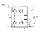
- the FIG. 1 shows an energy storage device 1 with a capacitor 4 as a first energy storage and a battery 5 from the second energy storage and a charge and discharge arrangement 13.
- the battery 5 has an internal resistance 12 and is via a throttle 7 and load / unload plates 10 and 11 with the vehicle busbar 2 connected to a rail vehicle, not shown.
- the vehicle busbar 2 also has a DC link capacitor 3 connected in parallel.
- the capacitor 4 with its internal resistance 14 is connected via a throttle 6 and the loading / unloading plates 8 and 9 with the vehicle bus bar 2.
- the charging / discharging plates ensure that the voltages of the battery, capacitor and vehicle busbar can be different.
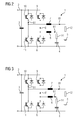
- FIG. 2 schematically shows how the energy storage device FIG. 1 can be used for heating. If the battery 5 is discharged via the internal resistance 12 (indicated by the arrows 61), a current flow into the capacitor 4 occurs via the actuator 10 and the actuator 9. The flow of current through the resistor 12 gives off heat which the battery 5 heating up.
- FIG. 3 is contrary to the FIG. 2 the discharge of the capacitor or the charging of the battery shown.
- the arrows 61 illustrate the current flowing from the capacitor through the throttle 6, which is supplied via the charge / discharge plates 9 and 10 and the throttle 7 via the internal resistance 12 of the battery 5.
- the energy storage arrangement is heated by the heat generated at the internal resistance 12.
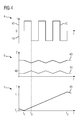
- the battery current I is plotted against the time t.
- the discharging 41 of the battery starts, from which a battery current characterized by the characteristic 40 arises until the time t2.
- the charging or discharging direction is reversed, resulting in charging the battery 42.
- the characteristic curve 40 illustrates the mutual charging of the battery and capacitor according to the FIGS. 1 to 3 ,
- the energy content E of the battery 4 is plotted against the time t.
- the characteristic curve 43 shows the energy content of the battery, while the characteristic 44 indicates the energy content of the capacitor.
- the method according to the invention begins with the charging of the capacitor and the discharging of the battery.
- the capacitor is fully charged at an energy level 48.
- the energy content of the battery 43 reaches a minimum at time t2 because the battery was used to fully charge the capacitor.
- three more charging or discharging cycles between battery and capacitor are shown.
- the battery temperature T is plotted against the time t.
- the temperature of the battery drops to the lower threshold T2 until time t1.
- the method according to the invention begins by alternately charging and discharging the battery and capacitor with the heating of the battery in accordance with the characteristic curve 45.
- the characteristic curve 45 of the battery temperature reaches upper threshold T1, so that the inventive method is terminated.
- the heating continues until time t3 at which the battery 5 has returned to its original energy and the process is terminated.
- the method can be aborted immediately upon reaching T1. In such case, the battery may have a lower energy content than at the beginning.
- the energy loss to cover the heat energy is in Fig. 4 not shown. This can in principle be taken from the participating energy stores, or can be replenished via the DC link if, for example, the vehicle is externally supplied with energy.
- FIG. 5 is shown in the vehicle, not shown, only the battery circuit with the battery 5.
- the elements internal resistance 12, throttle 7 and charging / discharging plates 10 and 11 and the busbar 2 and the intermediate circuit capacitor 31 correspond to the representation of FIG. 1 ,
- charging / discharging of the battery for the heating takes place by means of a direct interaction with the intermediate circuit capacitor 31. This is illustrated by the arrows 61.
- FIG. 6 is the same circuit design as in the FIG. 5 given, with the difference that an energy exchange for charging / discharging the battery 5 via the vehicle bus bar 2 with an external energy storage is carried out (not shown).
- the arrows 61 illustrate the flow of energy.
- the external energy store may be, for example, a stationary energy store of a charging station or else an energy store of another vehicle connected via a catenary.
- FIG. 7 A simplified operation of the energy storage device 50 according to FIG. 5 or 6 results when zero is specified as the DC setpoint for the battery 5 and the timing of the buck-boosters 10, 11 is released. This case is in the FIG. 7 shown.
- the representation corresponds to the in Figure 4 ac illustrated characteristics.
- Figure 7a shows that only an alternating current 71 (triangular) with the set clock frequency f of the actuator flows without the battery 5 is significantly charged or discharged thereby.
- the time axis is interrupted (dashed area tx), because due to the relatively high clock frequency f very many cycles are required until the battery 5 reaches the required temperature T1.
- the alternating current 71 causes the desired losses in the internal resistance of the battery, which heat them up, as in FIG. 7c shown.
Landscapes
- Engineering & Computer Science (AREA)
- Power Engineering (AREA)
- Transportation (AREA)
- Mechanical Engineering (AREA)
- Life Sciences & Earth Sciences (AREA)
- Sustainable Development (AREA)
- Sustainable Energy (AREA)
- Secondary Cells (AREA)
- Electric Propulsion And Braking For Vehicles (AREA)
- Vending Machines For Individual Products (AREA)
Applications Claiming Priority (1)
| Application Number | Priority Date | Filing Date | Title |
|---|---|---|---|
| DE102013208556.7A DE102013208556A1 (de) | 2013-05-08 | 2013-05-08 | Verfahren für ein Aufheizen einer Energiespeicheranordnung und Energiespeicheranordnung |
Publications (2)
| Publication Number | Publication Date |
|---|---|
| EP2801496A2 true EP2801496A2 (fr) | 2014-11-12 |
| EP2801496A3 EP2801496A3 (fr) | 2016-01-20 |
Family
ID=50639274
Family Applications (1)
| Application Number | Title | Priority Date | Filing Date |
|---|---|---|---|
| EP14166330.2A Withdrawn EP2801496A3 (fr) | 2013-05-08 | 2014-04-29 | Procédé de chauffage d'un système d'accumulation d'énergie et système d'accumulation d'énergie |
Country Status (2)
| Country | Link |
|---|---|
| EP (1) | EP2801496A3 (fr) |
| DE (1) | DE102013208556A1 (fr) |
Cited By (1)
| Publication number | Priority date | Publication date | Assignee | Title |
|---|---|---|---|---|
| WO2021018582A1 (fr) * | 2019-07-26 | 2021-02-04 | Siemens Mobility GmbH | Procédé de fonctionnement d'un véhicule ferroviaire et véhicule ferroviaire |
Families Citing this family (4)
| Publication number | Priority date | Publication date | Assignee | Title |
|---|---|---|---|---|
| DE102014007015B4 (de) | 2014-05-13 | 2026-04-16 | Audi Ag | Verfahren zum Temperieren einer elektrischen Energiespeichereinrichtung, Energiespeicheranordnung und Kraftfahrzeug |
| DE102016205333A1 (de) * | 2016-03-31 | 2017-10-05 | Siemens Aktiengesellschaft | Verfahren und Vorrichtung zum Temperieren eines Akkumulators |
| DE102018219824A1 (de) | 2018-11-20 | 2020-05-20 | Robert Bosch Gmbh | Antriebssystem für ein Elektrofahrzeug, Verfahren zum Betreiben eines Antriebssystems und Elektrofahrzeug |
| CN111181208A (zh) * | 2020-01-10 | 2020-05-19 | 武汉理工大学 | 一种集成交流加热功能的充电器 |
Family Cites Families (7)
| Publication number | Priority date | Publication date | Assignee | Title |
|---|---|---|---|---|
| US6882061B1 (en) * | 1998-12-31 | 2005-04-19 | Daimlerchrysler Corporation | Battery self-warming mechanism using the inverter and the battery main disconnect circuitry |
| JP4337848B2 (ja) * | 2006-07-10 | 2009-09-30 | トヨタ自動車株式会社 | 電源システムおよびそれを備える車両、ならびに温度管理方法 |
| DE102008044842A1 (de) * | 2008-08-28 | 2010-04-08 | Siemens Aktiengesellschaft | Vorrichtung zur Energieversorgung eines Bahnnetzes |
| US8452490B2 (en) * | 2009-12-14 | 2013-05-28 | Control Solutions LLC | Electronic circuit for charging and heating a battery |
| US9214706B2 (en) * | 2010-07-30 | 2015-12-15 | Byd Company Limited | Battery heating circuits and methods using resonance components in series based on charge balancing |
| CN102082306B (zh) * | 2010-07-30 | 2012-11-21 | 比亚迪股份有限公司 | 一种电池的加热电路 |
| DE102012205095A1 (de) * | 2012-03-29 | 2013-10-02 | Robert Bosch Gmbh | Verfahren zum Aufheizen von Energiespeicherzellen einer Energiespeichereinrichtung und aufheizbare Energiespeichereinrichtung |
-
2013
- 2013-05-08 DE DE102013208556.7A patent/DE102013208556A1/de not_active Withdrawn
-
2014
- 2014-04-29 EP EP14166330.2A patent/EP2801496A3/fr not_active Withdrawn
Non-Patent Citations (1)
| Title |
|---|
| None |
Cited By (1)
| Publication number | Priority date | Publication date | Assignee | Title |
|---|---|---|---|---|
| WO2021018582A1 (fr) * | 2019-07-26 | 2021-02-04 | Siemens Mobility GmbH | Procédé de fonctionnement d'un véhicule ferroviaire et véhicule ferroviaire |
Also Published As
| Publication number | Publication date |
|---|---|
| EP2801496A3 (fr) | 2016-01-20 |
| DE102013208556A1 (de) | 2014-11-13 |
Similar Documents
| Publication | Publication Date | Title |
|---|---|---|
| EP3665030B1 (fr) | Dispositif d'accumulation électrique destiné à fournir de l'énergie électrique pour une opération de charge d'au moins un véhicule automobile pouvant être propulsé à l'électricité ainsi que module de mise à niveau et procédé de fonctionnement | |
| EP3022433B1 (fr) | Disposition d'interrupteur dans un circuit de bord de véhicule à moteur | |
| DE102018213614B4 (de) | Mobile Ladesäule, Verfahren zum Betreiben einer mobilen Ladesäule | |
| DE102018221989A1 (de) | Hochvoltbordnetzanordnung für ein Kraftfahrzeug, Kraftfahrzeug und Verfahren zum Betreiben einer Hochvoltbordnetzanordnung | |
| EP2801496A2 (fr) | Procédé de chauffage d'un système d'accumulation d'énergie et système d'accumulation d'énergie | |
| EP2953227A1 (fr) | Réseau de bord pour un véhicule automobile | |
| EP3634803B1 (fr) | Source de puissance pour un vehicule ferroviare | |
| EP3342629B1 (fr) | Technique de connexion variable d'un système d'accumulation d'énergie de traction | |
| DE102010051323B4 (de) | Ladesystem zum Laden einer Batterie eines Fahrzeuges mit einem Zwei-Weg-Laderegler | |
| DE102020118904A1 (de) | Bordseitiger wechselstromgenerator für power-to-the-box in fahrzeugen mit einer brennkraftmaschine | |
| DE102015122676A1 (de) | System, verfahren und vorrichtung zum schützen eines obcausgangsanschlusses | |
| EP2985189A1 (fr) | Réseau de bord pour un véhicule, en particulier véhicule industriel | |
| DE102012011840B4 (de) | Bordnetz für ein Kraftfahrzeug | |
| DE102013013170A1 (de) | Batterie mit Temperiereinrichtung und Verfahren zum Temperieren einer Batterie | |
| EP3720733B1 (fr) | Procédé de commande d'une installation électrique d'un véhicule à moteur à entraînement électrique, dotée de plusieurs batteries et installation électrique d'un véhicule à entraînement électrique | |
| DE102015006307A1 (de) | Ladevorrichtung zum induktiven Laden eines elektrischen Energiespeichers eines Kraftfahrzeugs und Verfahren zum Betreiben einer Ladevorrichtung | |
| DE102022112558A1 (de) | Kraftfahrzeug mit einer fremderregten Synchronmaschine und Verfahren zur aktiven Entladung eines Kondensators in einem Hochspannungsnetz | |
| DE102019205423A1 (de) | Verfahren zum Betreiben einer Hochvolt-Bordnetzanordnung, Steuereinrichtung, Hochvolt-Bordnetzanordnung und Kraftfahrzeug | |
| EP3027462A1 (fr) | Ensemble d'accumulation d'énergie, système d'accumulation d'énergie et procédé permettant de faire fonctionner un ensemble d'accumulation d'énergie | |
| DE102012003046A1 (de) | Verfahren zum Laden einer Traktionsbatterie | |
| DE102016013668A1 (de) | Verfahren zum Erwärmen einer Batterie eines Hybridantriebsstrangs eines Fahrzeugs | |
| DE102013009991A1 (de) | Fremdstartfähige Integration einer Batterie in ein Kraftfahrzeug-Bordnetz | |
| DE102018132186A1 (de) | Speichereinheit für ein Bordnetz eines Fahrzeugs | |
| DE102004001025B3 (de) | Kraftfahrzuegbordnetz mit zwei Energiespeichern | |
| DE102018210979B4 (de) | Mehrspannungsbatterievorrichtung und Mehrspannungsbordnetz für ein Kraftfahrzeug |
Legal Events
| Date | Code | Title | Description |
|---|---|---|---|
| PUAI | Public reference made under article 153(3) epc to a published international application that has entered the european phase |
Free format text: ORIGINAL CODE: 0009012 |
|
| 17P | Request for examination filed |
Effective date: 20140429 |
|
| AK | Designated contracting states |
Kind code of ref document: A2 Designated state(s): AL AT BE BG CH CY CZ DE DK EE ES FI FR GB GR HR HU IE IS IT LI LT LU LV MC MK MT NL NO PL PT RO RS SE SI SK SM TR |
|
| AX | Request for extension of the european patent |
Extension state: BA ME |
|
| PUAL | Search report despatched |
Free format text: ORIGINAL CODE: 0009013 |
|
| AK | Designated contracting states |
Kind code of ref document: A3 Designated state(s): AL AT BE BG CH CY CZ DE DK EE ES FI FR GB GR HR HU IE IS IT LI LT LU LV MC MK MT NL NO PL PT RO RS SE SI SK SM TR |
|
| AX | Request for extension of the european patent |
Extension state: BA ME |
|
| RIC1 | Information provided on ipc code assigned before grant |
Ipc: B60L 11/00 20060101AFI20151211BHEP Ipc: B60L 11/18 20060101ALI20151211BHEP |
|
| STAA | Information on the status of an ep patent application or granted ep patent |
Free format text: STATUS: THE APPLICATION IS DEEMED TO BE WITHDRAWN |
|
| 18D | Application deemed to be withdrawn |
Effective date: 20160721 |