EP2803893B1 - Conduit de fluide flexible pour le transfert de chaleur - Google Patents
Conduit de fluide flexible pour le transfert de chaleur Download PDFInfo
- Publication number
- EP2803893B1 EP2803893B1 EP13005416.6A EP13005416A EP2803893B1 EP 2803893 B1 EP2803893 B1 EP 2803893B1 EP 13005416 A EP13005416 A EP 13005416A EP 2803893 B1 EP2803893 B1 EP 2803893B1
- Authority
- EP
- European Patent Office
- Prior art keywords
- tube
- sheath
- heat
- conducting
- layer
- Prior art date
- Legal status (The legal status is an assumption and is not a legal conclusion. Google has not performed a legal analysis and makes no representation as to the accuracy of the status listed.)
- Active
Links
Images




Classifications
-
- F—MECHANICAL ENGINEERING; LIGHTING; HEATING; WEAPONS; BLASTING
- F16—ENGINEERING ELEMENTS AND UNITS; GENERAL MEASURES FOR PRODUCING AND MAINTAINING EFFECTIVE FUNCTIONING OF MACHINES OR INSTALLATIONS; THERMAL INSULATION IN GENERAL
- F16L—PIPES; JOINTS OR FITTINGS FOR PIPES; SUPPORTS FOR PIPES, CABLES OR PROTECTIVE TUBING; MEANS FOR THERMAL INSULATION IN GENERAL
- F16L11/00—Hoses, i.e. flexible pipes
- F16L11/04—Hoses, i.e. flexible pipes made of rubber or flexible plastics
- F16L11/12—Hoses, i.e. flexible pipes made of rubber or flexible plastics with arrangements for particular purposes, e.g. specially profiled, with protecting layer, heated, electrically conducting
-
- F—MECHANICAL ENGINEERING; LIGHTING; HEATING; WEAPONS; BLASTING
- F28—HEAT EXCHANGE IN GENERAL
- F28F—DETAILS OF HEAT-EXCHANGE AND HEAT-TRANSFER APPARATUS, OF GENERAL APPLICATION
- F28F21/00—Constructions of heat-exchange apparatus characterised by the selection of particular materials
- F28F21/08—Constructions of heat-exchange apparatus characterised by the selection of particular materials of metal
- F28F21/089—Coatings, claddings or bonding layers made from metals or metal alloys
-
- F—MECHANICAL ENGINEERING; LIGHTING; HEATING; WEAPONS; BLASTING
- F16—ENGINEERING ELEMENTS AND UNITS; GENERAL MEASURES FOR PRODUCING AND MAINTAINING EFFECTIVE FUNCTIONING OF MACHINES OR INSTALLATIONS; THERMAL INSULATION IN GENERAL
- F16L—PIPES; JOINTS OR FITTINGS FOR PIPES; SUPPORTS FOR PIPES, CABLES OR PROTECTIVE TUBING; MEANS FOR THERMAL INSULATION IN GENERAL
- F16L11/00—Hoses, i.e. flexible pipes
-
- F—MECHANICAL ENGINEERING; LIGHTING; HEATING; WEAPONS; BLASTING
- F16—ENGINEERING ELEMENTS AND UNITS; GENERAL MEASURES FOR PRODUCING AND MAINTAINING EFFECTIVE FUNCTIONING OF MACHINES OR INSTALLATIONS; THERMAL INSULATION IN GENERAL
- F16L—PIPES; JOINTS OR FITTINGS FOR PIPES; SUPPORTS FOR PIPES, CABLES OR PROTECTIVE TUBING; MEANS FOR THERMAL INSULATION IN GENERAL
- F16L11/00—Hoses, i.e. flexible pipes
- F16L11/04—Hoses, i.e. flexible pipes made of rubber or flexible plastics
- F16L11/10—Hoses, i.e. flexible pipes made of rubber or flexible plastics with reinforcements not embedded in the wall
-
- F—MECHANICAL ENGINEERING; LIGHTING; HEATING; WEAPONS; BLASTING
- F16—ENGINEERING ELEMENTS AND UNITS; GENERAL MEASURES FOR PRODUCING AND MAINTAINING EFFECTIVE FUNCTIONING OF MACHINES OR INSTALLATIONS; THERMAL INSULATION IN GENERAL
- F16L—PIPES; JOINTS OR FITTINGS FOR PIPES; SUPPORTS FOR PIPES, CABLES OR PROTECTIVE TUBING; MEANS FOR THERMAL INSULATION IN GENERAL
- F16L11/00—Hoses, i.e. flexible pipes
- F16L11/04—Hoses, i.e. flexible pipes made of rubber or flexible plastics
- F16L11/11—Hoses, i.e. flexible pipes made of rubber or flexible plastics with corrugated wall
- F16L11/115—Hoses, i.e. flexible pipes made of rubber or flexible plastics with corrugated wall having reinforcements not embedded in the wall
-
- F—MECHANICAL ENGINEERING; LIGHTING; HEATING; WEAPONS; BLASTING
- F16—ENGINEERING ELEMENTS AND UNITS; GENERAL MEASURES FOR PRODUCING AND MAINTAINING EFFECTIVE FUNCTIONING OF MACHINES OR INSTALLATIONS; THERMAL INSULATION IN GENERAL
- F16L—PIPES; JOINTS OR FITTINGS FOR PIPES; SUPPORTS FOR PIPES, CABLES OR PROTECTIVE TUBING; MEANS FOR THERMAL INSULATION IN GENERAL
- F16L3/00—Supports for pipes, cables or protective tubing, e.g. hangers, holders, clamps, cleats, clips, brackets
- F16L3/02—Supports for pipes, cables or protective tubing, e.g. hangers, holders, clamps, cleats, clips, brackets partly surrounding the pipes, cables or protective tubing
- F16L3/04—Supports for pipes, cables or protective tubing, e.g. hangers, holders, clamps, cleats, clips, brackets partly surrounding the pipes, cables or protective tubing and pressing it against a wall or other support
-
- F—MECHANICAL ENGINEERING; LIGHTING; HEATING; WEAPONS; BLASTING
- F16—ENGINEERING ELEMENTS AND UNITS; GENERAL MEASURES FOR PRODUCING AND MAINTAINING EFFECTIVE FUNCTIONING OF MACHINES OR INSTALLATIONS; THERMAL INSULATION IN GENERAL
- F16L—PIPES; JOINTS OR FITTINGS FOR PIPES; SUPPORTS FOR PIPES, CABLES OR PROTECTIVE TUBING; MEANS FOR THERMAL INSULATION IN GENERAL
- F16L3/00—Supports for pipes, cables or protective tubing, e.g. hangers, holders, clamps, cleats, clips, brackets
- F16L3/08—Supports for pipes, cables or protective tubing, e.g. hangers, holders, clamps, cleats, clips, brackets substantially surrounding the pipe, cable or protective tubing
- F16L3/12—Supports for pipes, cables or protective tubing, e.g. hangers, holders, clamps, cleats, clips, brackets substantially surrounding the pipe, cable or protective tubing comprising a member substantially surrounding the pipe, cable or protective tubing
- F16L3/13—Supports for pipes, cables or protective tubing, e.g. hangers, holders, clamps, cleats, clips, brackets substantially surrounding the pipe, cable or protective tubing comprising a member substantially surrounding the pipe, cable or protective tubing and engaging it by snap action
-
- F—MECHANICAL ENGINEERING; LIGHTING; HEATING; WEAPONS; BLASTING
- F24—HEATING; RANGES; VENTILATING
- F24D—DOMESTIC- OR SPACE-HEATING SYSTEMS, e.g. CENTRAL HEATING SYSTEMS; DOMESTIC HOT-WATER SUPPLY SYSTEMS; ELEMENTS OR COMPONENTS THEREFOR
- F24D19/00—Details
- F24D19/0002—Means for connecting central heating radiators to circulation pipes
- F24D19/0017—Connections between supply and inlet or outlet of central heating radiators
- F24D19/0021—Flexible tubes or hoses
-
- F—MECHANICAL ENGINEERING; LIGHTING; HEATING; WEAPONS; BLASTING
- F24—HEATING; RANGES; VENTILATING
- F24D—DOMESTIC- OR SPACE-HEATING SYSTEMS, e.g. CENTRAL HEATING SYSTEMS; DOMESTIC HOT-WATER SUPPLY SYSTEMS; ELEMENTS OR COMPONENTS THEREFOR
- F24D3/00—Hot-water central heating systems
- F24D3/12—Tube and panel arrangements for ceiling, wall, or underfloor heating
- F24D3/14—Tube and panel arrangements for ceiling, wall, or underfloor heating incorporated in a ceiling, wall or floor
- F24D3/146—Tubes specially adapted for underfloor heating
-
- F—MECHANICAL ENGINEERING; LIGHTING; HEATING; WEAPONS; BLASTING
- F24—HEATING; RANGES; VENTILATING
- F24D—DOMESTIC- OR SPACE-HEATING SYSTEMS, e.g. CENTRAL HEATING SYSTEMS; DOMESTIC HOT-WATER SUPPLY SYSTEMS; ELEMENTS OR COMPONENTS THEREFOR
- F24D3/00—Hot-water central heating systems
- F24D3/12—Tube and panel arrangements for ceiling, wall, or underfloor heating
- F24D3/14—Tube and panel arrangements for ceiling, wall, or underfloor heating incorporated in a ceiling, wall or floor
- F24D3/148—Tube and panel arrangements for ceiling, wall, or underfloor heating incorporated in a ceiling, wall or floor with heat spreading plates
-
- F—MECHANICAL ENGINEERING; LIGHTING; HEATING; WEAPONS; BLASTING
- F24—HEATING; RANGES; VENTILATING
- F24S—SOLAR HEAT COLLECTORS; SOLAR HEAT SYSTEMS
- F24S10/00—Solar heat collectors using working fluids
- F24S10/70—Solar heat collectors using working fluids the working fluids being conveyed through tubular absorbing conduits
- F24S10/73—Solar heat collectors using working fluids the working fluids being conveyed through tubular absorbing conduits the tubular conduits being of plastic material
-
- F—MECHANICAL ENGINEERING; LIGHTING; HEATING; WEAPONS; BLASTING
- F24—HEATING; RANGES; VENTILATING
- F24S—SOLAR HEAT COLLECTORS; SOLAR HEAT SYSTEMS
- F24S80/00—Details, accessories or component parts of solar heat collectors not provided for in groups F24S10/00-F24S70/00
- F24S80/10—Materials for heat-exchange conduits
-
- F—MECHANICAL ENGINEERING; LIGHTING; HEATING; WEAPONS; BLASTING
- F24—HEATING; RANGES; VENTILATING
- F24T—GEOTHERMAL COLLECTORS; GEOTHERMAL SYSTEMS
- F24T10/00—Geothermal collectors
-
- F—MECHANICAL ENGINEERING; LIGHTING; HEATING; WEAPONS; BLASTING
- F24—HEATING; RANGES; VENTILATING
- F24T—GEOTHERMAL COLLECTORS; GEOTHERMAL SYSTEMS
- F24T10/00—Geothermal collectors
- F24T10/10—Geothermal collectors with circulation of working fluids through underground channels, the working fluids not coming into direct contact with the ground
-
- F—MECHANICAL ENGINEERING; LIGHTING; HEATING; WEAPONS; BLASTING
- F28—HEAT EXCHANGE IN GENERAL
- F28F—DETAILS OF HEAT-EXCHANGE AND HEAT-TRANSFER APPARATUS, OF GENERAL APPLICATION
- F28F1/00—Tubular elements; Assemblies of tubular elements
- F28F1/08—Tubular elements crimped or corrugated in longitudinal section
-
- F—MECHANICAL ENGINEERING; LIGHTING; HEATING; WEAPONS; BLASTING
- F28—HEAT EXCHANGE IN GENERAL
- F28F—DETAILS OF HEAT-EXCHANGE AND HEAT-TRANSFER APPARATUS, OF GENERAL APPLICATION
- F28F1/00—Tubular elements; Assemblies of tubular elements
- F28F1/10—Tubular elements and assemblies thereof with means for increasing heat-transfer area, e.g. with fins, with projections, with recesses
- F28F1/12—Tubular elements and assemblies thereof with means for increasing heat-transfer area, e.g. with fins, with projections, with recesses the means being only outside the tubular element
-
- F—MECHANICAL ENGINEERING; LIGHTING; HEATING; WEAPONS; BLASTING
- F28—HEAT EXCHANGE IN GENERAL
- F28F—DETAILS OF HEAT-EXCHANGE AND HEAT-TRANSFER APPARATUS, OF GENERAL APPLICATION
- F28F21/00—Constructions of heat-exchange apparatus characterised by the selection of particular materials
- F28F21/06—Constructions of heat-exchange apparatus characterised by the selection of particular materials of plastics material
- F28F21/061—Constructions of heat-exchange apparatus characterised by the selection of particular materials of plastics material for domestic or space-heating systems
-
- F—MECHANICAL ENGINEERING; LIGHTING; HEATING; WEAPONS; BLASTING
- F28—HEAT EXCHANGE IN GENERAL
- F28F—DETAILS OF HEAT-EXCHANGE AND HEAT-TRANSFER APPARATUS, OF GENERAL APPLICATION
- F28F21/00—Constructions of heat-exchange apparatus characterised by the selection of particular materials
- F28F21/06—Constructions of heat-exchange apparatus characterised by the selection of particular materials of plastics material
- F28F21/062—Constructions of heat-exchange apparatus characterised by the selection of particular materials of plastics material the heat-exchange apparatus employing tubular conduits
- F28F21/063—Constructions of heat-exchange apparatus characterised by the selection of particular materials of plastics material the heat-exchange apparatus employing tubular conduits for domestic or space-heating systems
-
- F—MECHANICAL ENGINEERING; LIGHTING; HEATING; WEAPONS; BLASTING
- F28—HEAT EXCHANGE IN GENERAL
- F28F—DETAILS OF HEAT-EXCHANGE AND HEAT-TRANSFER APPARATUS, OF GENERAL APPLICATION
- F28F21/00—Constructions of heat-exchange apparatus characterised by the selection of particular materials
- F28F21/08—Constructions of heat-exchange apparatus characterised by the selection of particular materials of metal
- F28F21/081—Heat exchange elements made from metals or metal alloys
- F28F21/084—Heat exchange elements made from metals or metal alloys from aluminium or aluminium alloys
-
- F—MECHANICAL ENGINEERING; LIGHTING; HEATING; WEAPONS; BLASTING
- F28—HEAT EXCHANGE IN GENERAL
- F28F—DETAILS OF HEAT-EXCHANGE AND HEAT-TRANSFER APPARATUS, OF GENERAL APPLICATION
- F28F21/00—Constructions of heat-exchange apparatus characterised by the selection of particular materials
- F28F21/08—Constructions of heat-exchange apparatus characterised by the selection of particular materials of metal
- F28F21/088—Constructions of heat-exchange apparatus characterised by the selection of particular materials of metal for domestic or space-heating systems
-
- F—MECHANICAL ENGINEERING; LIGHTING; HEATING; WEAPONS; BLASTING
- F24—HEATING; RANGES; VENTILATING
- F24D—DOMESTIC- OR SPACE-HEATING SYSTEMS, e.g. CENTRAL HEATING SYSTEMS; DOMESTIC HOT-WATER SUPPLY SYSTEMS; ELEMENTS OR COMPONENTS THEREFOR
- F24D3/00—Hot-water central heating systems
- F24D3/12—Tube and panel arrangements for ceiling, wall, or underfloor heating
- F24D3/14—Tube and panel arrangements for ceiling, wall, or underfloor heating incorporated in a ceiling, wall or floor
- F24D3/141—Tube mountings specially adapted therefor
- F24D3/142—Tube mountings specially adapted therefor integrated in prefab construction elements
-
- F—MECHANICAL ENGINEERING; LIGHTING; HEATING; WEAPONS; BLASTING
- F24—HEATING; RANGES; VENTILATING
- F24D—DOMESTIC- OR SPACE-HEATING SYSTEMS, e.g. CENTRAL HEATING SYSTEMS; DOMESTIC HOT-WATER SUPPLY SYSTEMS; ELEMENTS OR COMPONENTS THEREFOR
- F24D3/00—Hot-water central heating systems
- F24D3/12—Tube and panel arrangements for ceiling, wall, or underfloor heating
- F24D3/14—Tube and panel arrangements for ceiling, wall, or underfloor heating incorporated in a ceiling, wall or floor
- F24D3/141—Tube mountings specially adapted therefor
- F24D3/144—Clips for fastening heating tubes on a reinforcement net or mesh, e.g. mesh for concrete reinforcement
-
- F—MECHANICAL ENGINEERING; LIGHTING; HEATING; WEAPONS; BLASTING
- F28—HEAT EXCHANGE IN GENERAL
- F28F—DETAILS OF HEAT-EXCHANGE AND HEAT-TRANSFER APPARATUS, OF GENERAL APPLICATION
- F28F1/00—Tubular elements; Assemblies of tubular elements
- F28F1/10—Tubular elements and assemblies thereof with means for increasing heat-transfer area, e.g. with fins, with projections, with recesses
- F28F1/12—Tubular elements and assemblies thereof with means for increasing heat-transfer area, e.g. with fins, with projections, with recesses the means being only outside the tubular element
- F28F1/34—Tubular elements and assemblies thereof with means for increasing heat-transfer area, e.g. with fins, with projections, with recesses the means being only outside the tubular element and extending obliquely
- F28F1/36—Tubular elements and assemblies thereof with means for increasing heat-transfer area, e.g. with fins, with projections, with recesses the means being only outside the tubular element and extending obliquely the means being helically wound fins or wire spirals
-
- F—MECHANICAL ENGINEERING; LIGHTING; HEATING; WEAPONS; BLASTING
- F28—HEAT EXCHANGE IN GENERAL
- F28F—DETAILS OF HEAT-EXCHANGE AND HEAT-TRANSFER APPARATUS, OF GENERAL APPLICATION
- F28F2255/00—Heat exchanger elements made of materials having special features or resulting from particular manufacturing processes
- F28F2255/02—Flexible elements
-
- F—MECHANICAL ENGINEERING; LIGHTING; HEATING; WEAPONS; BLASTING
- F28—HEAT EXCHANGE IN GENERAL
- F28F—DETAILS OF HEAT-EXCHANGE AND HEAT-TRANSFER APPARATUS, OF GENERAL APPLICATION
- F28F2275/00—Fastening; Joining
- F28F2275/02—Fastening; Joining by using bonding materials; by embedding elements in particular materials
- F28F2275/025—Fastening; Joining by using bonding materials; by embedding elements in particular materials by using adhesives
-
- Y—GENERAL TAGGING OF NEW TECHNOLOGICAL DEVELOPMENTS; GENERAL TAGGING OF CROSS-SECTIONAL TECHNOLOGIES SPANNING OVER SEVERAL SECTIONS OF THE IPC; TECHNICAL SUBJECTS COVERED BY FORMER USPC CROSS-REFERENCE ART COLLECTIONS [XRACs] AND DIGESTS
- Y02—TECHNOLOGIES OR APPLICATIONS FOR MITIGATION OR ADAPTATION AGAINST CLIMATE CHANGE
- Y02B—CLIMATE CHANGE MITIGATION TECHNOLOGIES RELATED TO BUILDINGS, e.g. HOUSING, HOUSE APPLIANCES OR RELATED END-USER APPLICATIONS
- Y02B30/00—Energy efficient heating, ventilation or air conditioning [HVAC]
-
- Y—GENERAL TAGGING OF NEW TECHNOLOGICAL DEVELOPMENTS; GENERAL TAGGING OF CROSS-SECTIONAL TECHNOLOGIES SPANNING OVER SEVERAL SECTIONS OF THE IPC; TECHNICAL SUBJECTS COVERED BY FORMER USPC CROSS-REFERENCE ART COLLECTIONS [XRACs] AND DIGESTS
- Y02—TECHNOLOGIES OR APPLICATIONS FOR MITIGATION OR ADAPTATION AGAINST CLIMATE CHANGE
- Y02E—REDUCTION OF GREENHOUSE GAS [GHG] EMISSIONS, RELATED TO ENERGY GENERATION, TRANSMISSION OR DISTRIBUTION
- Y02E10/00—Energy generation through renewable energy sources
- Y02E10/10—Geothermal energy
-
- Y—GENERAL TAGGING OF NEW TECHNOLOGICAL DEVELOPMENTS; GENERAL TAGGING OF CROSS-SECTIONAL TECHNOLOGIES SPANNING OVER SEVERAL SECTIONS OF THE IPC; TECHNICAL SUBJECTS COVERED BY FORMER USPC CROSS-REFERENCE ART COLLECTIONS [XRACs] AND DIGESTS
- Y02—TECHNOLOGIES OR APPLICATIONS FOR MITIGATION OR ADAPTATION AGAINST CLIMATE CHANGE
- Y02E—REDUCTION OF GREENHOUSE GAS [GHG] EMISSIONS, RELATED TO ENERGY GENERATION, TRANSMISSION OR DISTRIBUTION
- Y02E10/00—Energy generation through renewable energy sources
- Y02E10/40—Solar thermal energy, e.g. solar towers
- Y02E10/44—Heat exchange systems
Definitions
- Heat transfer including radiant heating and cooling applied to domestic and commercial living and working spaces and solar and geothermal heat exchange.
- PEX tube cross-linked high-density polythene
- PEX tube is also used in heat transfer applications, most often in hot-water under-floor heating. In heat transfer applications that permit use of standard heat-exchange assemblies, such assemblies tend to be made of materials of high thermal conductivity: usually metals. PEX has a thermal conductivity that is 800x lower than copper and 100x lower than carbon steel. This disadvantage can be outweighed by the ability of PEX tube to be readily configured in-situ, allowing the use of custom tube layouts. For example, using flexible PEX tube, radiant heating or cooling systems can be customized in situ to suit living spaces of differing geometries and with differing heating or cooling needs. Similarly a solar heat collection system can be constructed in situ to fit the geometry of a roof or a geothermal heat transfer system can be configured to fit the geometry of a pond or pit.
- Heat transfer efficiency is improved by reducing the overall resistance of the thermal path between the heat transfer fluid inside the tube and the medium with which heat is being exchanged.
- the effect of reducing thermal resistance is to: (a) reduce the temperature drop for a given heat flux; (b) in the case of a heating system, allow a lower operating temperature of the heating medium; (c) in the case of a cooling system, allow a higher operating temperature of the cooling medium.
- the tube is fixed to a thermally conductive heat-diffusing or heat-collecting surface that is much larger than the surface are of the tube.
- Heat transfer efficiency is improved by: (a) fixing the tube so that substantially 100% of the exterior surface of the tube is in intimate contact with the conductive surface; (b) ensuring that the contact between the exterior surface of the tube and the conductive surface has no voids ie reducing thermal contact resistance.
- the tube can be sandwiched between shaped metal plates or embedded in a conductive layer such as graphite-loaded plaster.
- Flexible tube configured in situ can also be embedded.
- flexible tube used in under-floor heating is often embedded in a screed that is initially liquid and sets to a solid. Typically this screed is based on calcium silicate or calcium sulphate. These materials have the defect of poor thermal conductivity.
- a widely used alternative is to fix the tube to heat-conducting plates, usually made of aluminium sheet, or to a rigid panel with an aluminium layer.
- the aluminium sheet is formed into channels.
- the rigid panel is routed or molded to form channels and an aluminium layer is attached either pre-formed into channels or the layer is pressed into the panel.
- the inner diameter of the channels matches the outer diameter of the tube and the tube is pressed into the channels.
- the area of thermal contact can be increased by a further installation step in which a heat conducting strip is fixed to the plate, covering the channel and the tube within it.
- a heat conducting strip can be applied to straight sections of tube in the channel, but is difficult to apply to curved sections of channel, especially if this curvature is variable.
- Such a strip would be especially difficult to apply to a coiled tube layout.
- the steps required in this example demand a significant level of skill: (a) installing the channel-bearing heat-conducting plates (for example, on an insulating layer on a subfloor); (b) ensuring the channels are clean, for example by blowing out debris; (c) placing a layer of thermal filler (liquid, gel or paste) inside the channels; (d) pressing the flexible tube into the channels; (e) placing a layer of filler over the tube; (f) fixing a heat conducting flat strip over the channels and press down, removing excess filler; (g) continuing to press down until the filler has set.
- thermal filler liquid, gel or paste
- the present invention describes a modification of flexible tube that enables construction of a heat transfer system in which neither thermal filler nor a strip over the channel are required. At the same time, overall heat transfer performance is superior because: (a) substantially 100% of the surface area of the tube is in contact with the heat collecting/diffusing surface; (b) thermal contact resistance is low; (c) full contact between tube and plate is maintained over tube sections of any curvature.
- the present invention also describes how a modified flexible tube can be applied in a radiant heat transfer system that does not rely on channel-bearing plates or panels.
- Hydronic (water-based) radiant heat transfer systems using PEX tube are increasingly used to heat and cool living and working spaces.
- the efficiency of such systems increases as the operating temperature falls (for a heating system) or rises (for a cooling system).
- Lower operating temperatures are achievable in any hydronic radiant heating system and higher operating temperatures are achievable in any radiant cooling system by means of: (a) a larger radiant surface: this can transfer heat at a given rate at a lower radiant surface temperature; (b) a more uniform radiant surface temperature, achieved by reducing the thermal resistance of a layer on the thermal path in the plane of the radiant surface: the heat-diffusing layer (or in a cooling system, the heat-collecting layer); (c) lower thermal resistance through the entire thermal path between heat source and radiant-emitting surface (for a heating system) or between a heat sink and a radiant collecting surface (for a cooling system), so enabling heat to be transferred at a given rate at a lower temperature of heating medium for a given surface temperature; (d) lower thermal mass and faster, zoned controls, enabling the system to respond more rapidly to local changes in required heating (or cooling) load, avoiding periods of unnecessary heating (or cooling).
- wall radiators heat mainly by convection, resulting in currents of warm air moving to the ceiling. This is the opposite of the temperature profile that is ideal for comfort.
- Wall radiators have limited radiant area and have to be run at higher temperatures, meaning lower system efficiency.
- Typical wall radiators systems require circulating water temperatures around 60-75 °C. Operating temperatures for a typical under-floor radiant system are around 30-35 °C.
- the aesthetics of wall radiators are generally poor: wall radiators are obtrusive and impede the arrangement of furniture.
- the defects of wall radiators can be remedied by under-floor radiant heating.
- the temperature distribution through the living space is almost ideal for comfort.
- the entire floor becomes the radiating surface so that the system can run at lower temperatures.
- the system is invisible and the arrangement of furniture is not impeded.
- Hydronic under-floor heating has been widely adopted in Europe. For example, in Germany around 75% of new build homes use this form of heating. In the UK, hydronic underfloor heating is only 5% of the domestic heating market but is growing rapidly. In the USA, space-heating has been strongly influenced by the wide use of air-conditioning. Fans and ducts installed for air-conditioning can also be used for air-heating. As a result, forced-air heating is used in a round 70% of US homes, usually with a gas furnace as heat source. The forced air system is relatively cheap in newly-built structures, provides a fast response and the visual aesthetics are acceptable. The main defect is poor comfort: the temperature distribution is uneven. There is also noise and the potential spread of allergens. Zone control is less effective.
- PEX is used in under-floor radiant heating by fixing the tube in a serpentine or coiled layout in the plane of the floor. A number of different methods are used:
- the present invention offers a solution to these defects. Before describing this solution, it is helpful to define what is meant by flexible tube.
- PEX tube is an instance of a class of flexible and elastic tubes of relatively low thermal conductivity that can be used to conduct a heat transfer fluid.
- the flexibility and elasticity of such tube allows it to be easily arranged in a tightly curved layout by manual methods, where such a layout can be, for example: (a) a flat meander or serpentine; (b) a raised meander, for example, a meander on a cylindrical surface; (c) a flat coil or spiral; (d) a raised coil or helix.
- BR bending radius
- BR depends on: (a) the extensibility and compressibility of the material of the tube; (b) the temperature of the material at the time of bending: for example, the bending radius of PEX is increased by a factor of over 2x if the temperature is reduced from 20 to 0°C; if the temperature is raised to 130°C, this is the softening temperature of PEX and the bend radius is greatly reduced; (c) the method of bending (incorporating sand or ball bearings or a snugly-fitting spring into the tube inhibits kinking); (d) duration of bending; (e) the profile of the wall of the tube (smooth v corrugated); (f) the thickness of the wall of the tube; (g) reinforcement of the tube, for example by a
- BR 3 to 4 so that copper can be configured in a suitable serpentine.
- copper is relatively stiff, having a modulus of elasticity of 105-120 Gpa: this is 50-100x the modulus of elasticity of common polymers.
- copper requires special bending equipment: creation of an extensive custom curved layout in situ is impractical.
- the present invention concerns relatively elastic tube, where this can be defined as having a modulus of elasticity less than 2 GPa.
- modulus of elasticity are: rubber: 0.01-0.1 GPa; low density polythene: 0.24 GPa; polyurethane: 0.1-0.7 GPa; polypropylene: 1.5 GPa; nylon 6: 1.8 GPa;
- the present invention also concerns flexible and elastic tube that has low thermal conductivity where this is defined to be less than 2 W/m°C. Most common polymers have a thermal conductivity less than 1 W/m°C. For example, the thermal conductivity of PEX is around 0.45 W/m°C.
- the tube may need to be heated, for example, by using a hot-air blower.
- the temperature range of PEX is -100°C to +110°C, making PEX suitable for a variety of heating and cooling applications.
- BR poly vinyl chloride
- the modulus of elasticity is around 3.2 Gpa. If the tube is warmed to around 40°C, BR is reduced to about 10 and elasticity is greatly increased. Therefore, by warming the PVC tube using simple methods (such as interior electrical heating), it is possible to construct a useful curved layout.
- the temperature range is 0 to 60°C. This narrow range limits the utility of rigid PVC in heat transfer applications. Chlorinated PVC has a wider range: from -40°C to +90°C.
- PVC can be made highly flexible by adding plasticizer.
- flexible PVC is extruded round a steel helix.
- BR 2 to 3, allowing a useful curved layout to be constructed.
- this kind of tube may be used for heating or cooling of consumable liquids. The temperature range is -20°C to +90°C.
- BR Typical values of BR are in the range 2 to 10.
- PVC reinforced with nylon braid For example: (a) PVC reinforced with nylon braid; (b) silicone rubber reinforced with fibre-glass braid; (c) neoprene reinforced with steel wire braid; (d) polyurethane reinforced with polyester braid; (e) nylon reinforced with steel wire braid.
- PEX tube may have multiple layers.
- the layers in Al-PEX are in sequence from the inside of the tube: PEX, bonding agent, aluminium, bonding agent, PEX.
- the aluminium layer prevents diffusion of oxygen through the walls of the tube.
- the aluminium layer is created by folding a strip of metal round the inner PEX tube and by butt-welding this strip.
- a typical PEX tube of 16mm OD has an aluminium layer of 0.2mm inside a wall that is 2.5mm thick.
- the aluminium is a ductile and malleable alloy that allows bending of the tube.
- the aluminium layer makes the tube stiffer than a tube made entirely of HDPE, it is still easy to create a desired curved layout manually.
- the preferred aluminium alloy is 3003 H0: low temper, high-purity aluminium (around 97% pure) with a small amount of manganese (1-1.5%) added.
- FR 2474677A describes a flexible plastic tube for application that include heating or cooling of living space and de-icing of exterior surfaces.
- the flexible tube has an outer longitudinal metal layer that is glued, welded or pressed on to the plastic tube.
- the metal layer is wrapped at least round half the circumference of the tube. This document is considered as closest prior art to the subject of claim 1.
- DE202009003394U1 discloses a flexible conduit comprising a flexible tube with smooth inner and outer surface , a metallic sheath formed by a metallic winding embedded in a flexible and soft plastic material. This conduit is intended to conduct air conditioning.
- CN 201706080U discloses a different construction wherein the tube is not produced uniformly smooth, but embeds a sheathing helicoidal member.
- Tube, insulating layer and heat-spreading layer can all be cut and trimmed with simple tools. Maintenance is also easy since it is easy to disassemble the system for example, to trace and repair a leak. Disassembly is especially easy where bolts have been used to secure the conducting layer.
- a flexible sheath covers the exterior surface of the flexible tube.
- the sheath has high thermal conductivity.
- High thermal conductivity is defined to be greater than 15 W/m°C.
- Suitable materials include: stainless steel (15-20 W/m°C); carbon steel (40-50 W/m°C); aluminium alloy (150-230 W/m°C); high purity aluminium (greater than 99% pure) (240 W/m°C); copper (400 W/m°C); graphite (in plane) (50-500 W/m°C).
- High conductivity improves heat transfer from heat transfer fluid to heat-conducting surface:(a) radially through the sheathed tube; (b) circumferentially through the sheath, enabling the sheath to bridge gaps in the contact between sheath and surface. Based on the ratio of conductivity to cost, high purity aluminium is a preferred material for the sheath.
- a flexible conductive sheath is a spiral of conductive strip (wire or tape) that is wrapped round the tube. Uniform gaps between the turns of the spiral strip permit flexing of the tube. In order to accommodate a bending ratio of 5x, the apparently required uniform gap represents 20% of the length of the sheath. This assumes that the material of the spiral strip is incompressible. If the material used is soft (ie malleable, deformable), a much smaller gap is required. For example, using soft (ie high purity) aluminium 0.5mm OD wire wound round standard 16mm OD PEX tube, the required uniform gap is less than 5 % of the length of the sheath.
- the sheath is a series of rings. Uniform gaps between the rings permit flexing of the tube.
- the material of the rings or of the tape or wire can be graphite or metal.
- the sheath is made of soft deformable material. A sheath of deformable material, when pressed against a conducting surface, tends to conform with that surface, lowering the thermal contact resistance.
- Suitable deformable materials include high purity aluminium, high purity copper and graphite.
- a radiant heat transfer system can be used for either heating or cooling.
- the conducting surface is a heat diffuser.
- the conducting surface is a heat-collector. Radiant cooling systems require additional controls to prevent operation below the dew-point and/or should include provision for collecting and removing condensate.
- the heat transfer medium in a hydronic system is water.
- Water may be combined with, for example, anti-freeze and corrosion inhibitor.
- Alternative heat transfer media can be used: for example, oil or synthetic media.
- the same general design can be used for a radiant heat transfer system that is fixed in the floor, or in the wall or in the ceiling or suspended from the ceiling or fixed on a roof or similar exterior structure.
- the conducting surface is a sun-facing heat collector that can be, for example, an aluminium plate that has a blackened face to improve heat absorption. Above the plate is an air gap and a transparent cover. Flexible tube such as PEX does not tend to rupture when water carried in the tube freezes. This means that water used for space heating can be directly circulated through the solar collector, avoiding the added cost, space requirement and thermal resistance of an intermediate heat exchanger.
- a sun-facing heat collector can be, for example, an aluminium plate that has a blackened face to improve heat absorption.
- Above the plate is an air gap and a transparent cover.
- Flexible tube such as PEX does not tend to rupture when water carried in the tube freezes. This means that water used for space heating can be directly circulated through the solar collector, avoiding the added cost, space requirement and thermal resistance of an intermediate heat exchanger.
- a castellated mat or insulating layer can be used: the castellations can be flat-topped and able to support loads placed on the conducting layer. If the radiant system is fixed in the wall or the ceiling it may not bear significant loads. In this case, it is possible to fix the conducting layer to flat-topped castellations that are widely dispersed and which play no role in holding the tube layout.
- the sheathed tube can held be in a custom layout on the insulating layer by, for example, (a) cable ties; (b) omega-shaped clips; (c) omega -shaped guides; (d) adhesive, for example, using peel-off adhesive pads; (e) Velcro strip.
- a custom tube layout can be fixed rapidly using cable ties that are threaded through eyelets embedded in the insulating layer and round the tube.
- Standard cable ties would obstruct the thermal contact between tube and conducting layer. This effect can be mitigated by: (a) making the ties of heat conducting material where the ties wrap round the tube; (b) making the ties as thin as possible; (c) using a thermal filler such as silicone sealant between tube and conducting layer.
- the sheathed tube is fixed by clips with an omega cross-section.
- the clips can be fixed to the insulating layer in any location, using adhesive, for example, peel-off adhesive, on a flat base.
- the clips can have barbed stems or screw stems that can be inserted into the insulating layer or stems that snap into holes that form an array on the insulating layer.
- the sheathed tube is fixed by rigid straight or curved guides with an omega cross-section, also fixed to the insulating layer by adhesive or by barbs.
- the omega cross-section of the clips and guides leaves the upper surface of the tube free to press against the conducting layer.
- the rigid conducting layer is a heat conducting plate or array of conducting plates.
- this layer is aluminium alloy.
- High-purity aluminium (greater than 99.6% pure) has a thermal conductivity (234 watts/m°C) that is higher than any aluminium alloy but is weak (tensile strength 83 Mpa). If the design heat load requires only a thin conducting layer, high-purity aluminium may be: (a) insufficiently rigid to apply effective pressure to the sheathed tube; (b) vulnerable to damage during installation; (c) unable to support weight where the plate is under-floor.
- High-strength aluminium alloy (for example 2000 series or 7000 series alloys) has tensile strengths 4-5 x higher than 99.6% pure aluminium but thermal conductivities can be 40% less. A possible compromise is a subset of 6000 series alloys that offers over twice the tensile strength of high purity aluminium for a reduction of 10-15% in thermal conductivity.
- high-purity aluminium can be fixed to a reinforcing conducting layer.
- the reinforcing layer can be high-strength aluminium alloy or steel (for example, A36 structural steel).
- High-purity aluminium sheet can be cold-welded to aluminum alloy sheet or to steel sheet by high pressure rolling. Steel with a hot-dipped layer of high-purity aluminium is available from multiple suppliers.
- the rigid conducting layer is graphite foil backed by a reinforcing conducting layer.
- a commercially available graphite foil has an in-plane thermal conductivity (190 W/m°C), comparable with aluminium alloys, and is also soft, so that compressive thermal contact with the tube is assisted.
- Graphite foils are also available with in-plane conductivities up 3x higher than pure aluminium. Currently such foils are expensive.
- the rigid conducting layer can be fixed over the tube with compressive force by using an array of bolts that engage in sockets fixed in the insulating layer.
- the sockets can be anchored in the insulating layer by reinforcement, either embedded in the insulating layer or fixed to the back of the insulating layer. If a castellated insulating layer is used, the sockets can be embedded in the centres of the castellations.
- the conducting layer can be fixed by adhesive to the flat tops of the castellations.
- contact adhesive can be used and the conducting layer is pressed down, for example, by bolts, screws, by manual pressure, by the use of weights or by the use of clamps.
- the height of the castellations is slightly less than the height of the laid-out tube so that adhesive contact between the castellations and the conducting layer requires the sheathed tube to be deformed by compression.
- Sheathed tube can also be used in fixed channels. For example, channel-bearing insulating panels are fixed to a rigid substrate so that the channels link and form a continuous curving channel. Channel-bearing heat-conducting plates are then fitted into the insulating panels. The channels have an omega cross-section. Lastly, sheathed tube is snapped into the channels in the plates.
- channel-bearing insulated panels are manufactured with a continuous heat-conducting layer fixed (for example, by adhesive) to the panels on the channeled surface.
- a slit is cut through the conducting layer along the centre-line of each channel.
- the panels are fixed to a rigid substrate so that the slits link and form a continuous curving slit.
- Sheathed tube is pressed into the slit so that the conducting layer deforms around the tube and locks it into the channel. The deformation results in good thermal contact between the sheath and the conducting layer.
- the conducting layer is usually aluminium plate and this usually has only straight channels. This is because a curved channel is a compound curve that requires special pressing methods. Because the sheathed tube does not require wrap-round contact with the inner surface of the channel, contact between tube and conducting layer can continue round all curves while avoiding compound curve pressing. In the example of the slitted conducting layer, just described, the sheathed tube engages only with the deformed edge of the conducting layer.
- the described sheathed flexible tube can be used in a geothermal pond.
- a geothermal pond For example: (a) channel-bearing metal plates are fixed to a frame to form an array of vertical panels with horizontal channels having an omega cross-section; (b) sheathed tube is snapped into the channels to form a continuous serpentine; (c) the assembly of frame, panels and serpentine is floated on to the geothermal pond and sunk.
- the sheathed flexible tube is wound with uniform gaps between turns on to metal pipe and the assembly is sunk in the pond.
- the described sheathed flexible tube can also be used in a geothermal trench or borehole. For example: (a) sheathed tube is snapped into channels in a series of metal plates; (b) the tube and plates are inserted into a trench.
- Figure 1a flexible tube sheathed by a spiral strip.
- Figure 1a is a side view of a sheathed tube (10) comprising a flexible fluid-bearing tube (11) with a flexible heat-conducting sheath that is a spiral strip (12), tightly wrapped round the tube (11).
- the spiral strip (12) can be a wire or a tape and is made of heat conducting material.
- the material has a thermal conductivity greater than 15 W/m°C and is preferably easily deformed (ie malleable and ductile).
- a suitable deformable heat-conducting material is high purity aluminium.
- the spirals (12) of the sheath are separated by uniform gaps (13) that permit bending of the sheathed tube (10).
- Figure 1b flexible tube sheathed by a series of rings.
- Figure 1a is a side view of a sheathed tube (10) comprising a flexible fluid-bearing tube (11) with a flexible heat-conducting sheath that is a series of rings (14) tightly wrapped round the tube (11).
- the rings (14) can be wire or strip or tape and are made of heat conducting material.
- the material has a thermal conductivity greater than 15 W/m°C and is preferably easily deformed (ie malleable and ductile).
- a suitable deformable heat-conducting material is high purity aluminium.
- the rings (14) are separated by uniform gaps (15) that permit bending of the sheathed tube (10).
- Figure 1c detail of bonding agent applied to the sheath.
- Figure 1c is a cross-section in side view of one wall of the sheathed tube (10).
- Pressed against the fluid-bearing tube (11) is a series of spiral wires (12) separated by uniform gaps (13).
- Fixed in the gaps (13) is a layer of flexible adhesive (16).
- the adhesive (16) can be applied as follows: (a) the spiral wire (12) is wound tightly around the tube (11); (b) the adhesive (16) is painted on to the spiral (12) and then wiped off, using a motion at right angles to the spiral (12), so leaving adhesive in the gaps (13).
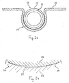
- Figure 2a flexible sheathed tube inside an omega-shaped channel in a conducting surface.
- Figure 2a shows the cross-section of a flexible sheathed tube (10) installed in the omega-shaped channel (20) of a heat diffusing/collecting plate (21).
- the sheathed tube (10) comprises a flexible, fluid-bearing tube (11) with a flexible, heat-conducting outer sheath (22).
- the sheath (22) is tightly fitted to the outer surface of the tube (11) and fixed to the tube (11) using a layer of flexible adhesive (not shown).
- the sheath (22) provides a thermal path between the entire outer surface of the tube (11) and the plate (21).
- An array (not shown) of plates (21) with channels (20) can support a desired curved pattern of flexible sheathed tube (10).
- Figure 2b thermal bypass formed by the sheath.
- Figure 2b shows a cross-section of the interface between a portion of the sheath (22) and an adjacent portion of a heat-conducting surface (23) such as the inner surface of the groove (20: see Figure 2a ).
- Good thermal contact between sheath (22) and surface (23) is shown at two zones (24) with an air gap (25) in between the zones (24).
- the sheath (22) provides a thermal bypass around the gap (25)
- Figure 3a sheathed tube with malleable sheath in non-compressive contact with a conducting surface.
- Figure 3a shows a cross-section of a flexible fluid-bearing tube (11) with sheath (22) in contact with a rigid planar insulating surface (30) and a rigid planar heat-conducting surface (31). The contact is non-compressive so that the contact area between sheath (22) and conducting surface (31) is small. The thermal contact resistance is significant.
- Figure 3b sheathed tube with malleable sheath in compressive contact with a conducting surface.
- Figure 3b shows a cross-section of a flexible fluid-bearing tube (11) with flexible heat-conducting sheath (22) in contact with a rigid planar insulating surface (30) and a rigid planar heat-conducting surface (31).
- the contact is compressive and in this instance, the sheath (22) is made of malleable material.
- the tube (11) and sheath (22) distort and the sheath (22) deforms, so that the contact area is increased; also the thermal contact resistance is reduced.
- Compressive contact can be achieved by a variety of means (not shown) that pull or push the rigid planar surfaces (30, 31) towards each other and hold these surfaces (30,31) in position.
- the contact between sheath (22) and heat-conducting surface (31) is sufficiently compressive to cause distortion of the tube (11) and deformation of the sheath (22), whereby overall thermal resistance is reduced.
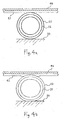
- Figure 4a sheathed tube in non-compressive contact with a conducting surface with malleable layer.
- Figure 4a shows a cross-section of a flexible fluid-bearing tube (11) with sheath (22) in contact with a rigid planar insulating surface (30) and a rigid planar heat-conducting surface comprising two layers: a rigid layer (40) and a malleable layer (41).
- the contact is non-compressive so that the contact area is small.
- the thermal contact resistance is significant.
- Figure 4b sheathed tube in compressive contact with a conducting surface with malleable layer.
- Figure 4b shows a cross-section of a flexible fluid-bearing tube (11) with sheath (22) in contact with a rigid planar insulating surface (30) and a rigid planar heat-conducting surface comprising two layers: a rigid layer (40) and a malleable layer (41).
- the contact is compressive.
- the tube (11) and sheath (22) distort and the malleable layer (41) deforms, so that the contact area is increased; also the thermal contact resistance is reduced.
- the contact between sheath (22) and heat-conducting surface is sufficiently compressive to cause distortion of the tube (11) and deformation of a malleable layer (41) in the heat-conducting surface (30), whereby overall thermal resistance is reduced.
- Figure 5a sheathed tube in omega-shaped clip with adhesive base.
- Figure 5a shows a cross-section of a flexible fluid-bearing tube (11) with flexible heat-conducting sheath (22).
- the sheath (22) is held in an omega-shaped channel formed by a clip (50) fixed to a flat base (51).
- a portion (52) of the tube (11) and the sheath (22) projects above the clip (50).
- the flat base (51) is attached to a rigid substrate (53) by an adhesive layer (54).
- the substrate (53) can be an insulating layer.
- the adhesive layer (54) is a peel-off contact adhesive.
- Figure 5b sheathed tube in omega-shaped clip with barbed base.
- Figure 5b shows a cross-section of a flexible fluid-bearing tube (11) with flexible heat-conducting sheath (22).
- the sheath (22) is held in an omega-shaped channel formed by a clip (50) fixed to a base with barbs (55).
- a portion (52) of the tube (11) and the sheath (22) projects above the clip (50).
- the barbs (55) are inserted into a rigid substrate (53).
- Figure 5c sheathed tube in omega-shaped clip with screw-in base.
- Figure 5c shows a cross-section of a flexible fluid-bearing tube (11) with flexible heat-conducting sheath (22).
- the sheath (22) is held in an omega-shaped channel formed by a clip (50) fixed to a base with a screw (56).
- a portion (52) of the tube (11) and the sheath (22) projects above the clip (50).
- the screw (56) is inserted into a rigid substrate (53).
- clips (50) as described in Figures 5a, 5b and 5c can be fixed on a suitable rigid substrate (53) so as to support a sheathed tube in a desired curved pattern.
- the clips (50) shown in Figures 5a, 5b, 5c can be made of a moldable polymer such as polypropylene.
- the sheath (22) projects above the clips (50) so that a conducting surface (not shown) can be pressed down on the sheath (22).
- the clips (50) cannot support a significant load so that other load-bearing means (not shown) are required.
- castellations can be used (see Figures 8a, 8b ). Clips are widely used to pin down flexible tube in radiant heating but the conventional clips differ from those shown in Figures 5a, 5b, 5c :
- Figure 6a sheathed tube over u-shaped channel with slotted conducting layer.
- Figure 6a shows a cross-section of a flexible fluid-bearing tube (11) with flexible heat-conducting sheath (22).
- Below the tube (11) with sheath (22) is shown in cross-section a deformable heat-conducting layer (60) fixed to a rigid planar substrate (61).
- the conducting layer (60) covers a u-shaped channel (62) in the substrate (61).
- Penetrating the conducting layer (60) is a slit (63) that is centred over the u-shaped channel (62) and runs parallel with the channel (62).
- Figure 6b sheathed tube in u-shaped channel held by a bent conducting layer .
- Figure 6b shows a cross-section of a flexible fluid-bearing tube (11) with flexible heat-conducting sheath (22) after the tube (11) with sheath (22) has been pressed down on the slit (63: see Figure 6a ) above the u-shaped channel (62).
- the heat-conducting layer (60) On each side of the channel (62) the heat-conducting layer (60) has been bent back.
- the sheath (22) is held firmly in the channel (62) and the thermal contact resistance between sheath (22) and conducting layer (60) is low.
- An array of panels (not shown) with u-shaped channels (62) and an attached conducting layer (60) with slits (63) can support a desired curved pattern of sheathed tube (10).
- the slit (63) can be substituted by another form of puncturing of the conducting layer (60): for example, a line of closely spaced perforations (not shown).
- Figure 7a serpentine tube layout for radiant heat transfer.
- Figure 7a shows in plan view an example of a simple serpentine layout of a flexible fluid-bearing sheathed tube (10) for radiant under-floor heating.
- the tube (10) conducts hot heat transfer fluid from a manifold (70) to a zone requiring higher heat transfer rates (71) such as a zone adjacent to a large exterior window. This zone (71) requires closer spacing of the sheathed tube (10).
- the tube (10) continues with wider spacing and returns to the manifold (70).
- the direction of fluid flow (76) is shown by arrows.
- the heat transfer fluid is water.
- Means of fixing the sheathed tube (10) in a desired layout are not shown but are described under Figures 2 , 5 , 6 and 8 .
- Figure 7b layers of radiant heat transfer system.
- Figure 7b shows in cross-section the possible layers of a radiant under-floor heating system.
- the lowest layer is a rigid planar substrate (73) that can be a subfloor.
- Fixed to the substrate (73) is an insulating layer (74).
- Fixed to the insulating layer is the sheathed tube (10) laid out in a curved pattern.
- Fixed to the top of the sheathed tube (10) is a rigid planar heat-conducting surface (75).
- Other layers can be placed on the conducting surface (75): such layers can include ceramic tile, engineered wood plank, carpet and so on.
- Means of fixing the sheathed tube (10) in a desired layout are not shown but are described under Figures 2 , 5 , 6 and 8 .
- Figure 8a serpentine tube layout using a castellated surface.
- Figure 8a shows in plan view a flexible sheathed tube (10) in an example of a serpentine layout on a rigid planar castellated surface (80).
- the castellations (81) are rigid protrusions arranged in a uniform grid. By weaving the tube (10) between castellations (81) the tube (10) can be fixed in a desired curving pattern.
- the geometry of the castellated surface (80) enables the sheathed tube (10) to be securely gripped and at the same time, a portion of the sheathed tube (10) projects above the castellations (81).
- Figure 8b layers of radiant heat transfer system using a castellated surface.
- Figure 8b shows in cross-section the possible layers of a radiant heat transfer system using a castellated surface (80).
- the first layer is a rigid substrate (82).
- the substrate (82) can be a subfloor.
- the substrate (82) can be wall-panels.
- the substrate (82) can be panels on a suspended frame.
- a layer with a castellated surface (80) Fixed to the substrate (82) by an adhesive layer (83) is a layer with a castellated surface (80) that can comprise rigid insulation into which a uniform grid of castellations (81) is molded.
- the castellated layer (80) is rigid polyurethane foam.
- the castellations (81) have flat tops and concave faces and provide channels (84) that can retain the sheathed tube (10) in a desired curved pattern.
- the dimensions of the channels (84) ensure that a portion of the sheathed tube (10) projects above the castellations (81).
- Shown above the castellated layer (80) is a rigid heat-conducting layer (85) that is pressed against an adhesive layer (86) on the flat tops of the castellations (81).
- the conducting layer (85) When the conducting layer (85) is pressed against the adhesive layer (86) in the direction shown (87), the conducting layer (85) is in compressive contact with the sheathed tube (10), meaning that the sheathed tube (10) distorts and the sheath (22: see Figure 3b ) deforms sufficiently to significantly reduce thermal resistance between the heat transfer fluid carried in the sheathed tube (10) and the conducting layer (85).
- the adhesive layer (86) can be peel-off contact adhesive. Instead of, or in addition to, the adhesive layer (86), bolts or screws (not shown) can be used to fix the conducting layer (85) to the castellated surface (84) with compressive contact between the conducting layer (85) and the sheathed tube (10).
- FIG. 9a roof - mounted panels and layout for solar heating. This figure gives a plan view of a hipped roof (90) and an array of solar panels of standard size (91). Indicated by a dotted line is an example of an underlying simple serpentine of sheathed tube (10). Water or water with anti-freeze agent, or other heat-transfer fluid, is circulated through the serpentine.
- Figure 9b layers of solar heating system. This figure shows a cross-section of a portion of the system shown in Figure 9a .
- each panel (91) is a transparent sheet (92) that is, for example, glass or acrylic. This sheet (92) is separated from a planar, rigid, heat-conducting surface (93) by an air gap (94).
- the top layer (95) of the conducting surface (93) is coloured black to aid absorption of heat.
- the conducting surface (93) is aluminium plate and the top layer (95) is anodized.
- the transparent layer (92) and conducting layer (93) of each panel (91) are held together along the edges by a rectangular frame (not shown).
- the frames can be linked, for example, by tongue and groove edges (not shown) so that panels (91) can be linked into a continuous array.
- the underside of the conducting surface (93) is fixed by a layer of adhesive (96) to the flat tops of castellations (97) in a castellated surface (98).
- the conducting surface is in compressive contact with sheathed tube (10): shown here with deformation of the sheath (22).
- the adhesive (96) can be peel-off contact adhesive.
- the sheathed tube (10) is held in channels (99) between the castellations (97).
- the castellated surface (98) is fastened to an insulating layer (910) by a layer of adhesive (911).
- a method for the panels (91) to a roof (90) in a customized layout of flexible sheathed tube (10) is as follows:
Landscapes
- Engineering & Computer Science (AREA)
- General Engineering & Computer Science (AREA)
- Mechanical Engineering (AREA)
- Physics & Mathematics (AREA)
- Thermal Sciences (AREA)
- Chemical & Material Sciences (AREA)
- Combustion & Propulsion (AREA)
- Life Sciences & Earth Sciences (AREA)
- Sustainable Development (AREA)
- Sustainable Energy (AREA)
- Geometry (AREA)
- Rigid Pipes And Flexible Pipes (AREA)
Claims (13)
- Un conduit flexible utilisé pour des transferts de chaleur comprenant:a. un tube flexible (11) disposé de sorte à acheminer un fluide caloporteur, lequel tube (11) a une épaisseur uniforme de paroi et une surface intérieure et extérieure sensiblement lisses;b. entourant ladite surface extérieure dudit tube (11) et contiguë à celui-ci, une gaine (12, 14, 22), dont le matériau a une conductivité thermique supérieure à 15 W/m°C;c. ladite gaine (12, 14, 22) soyant composée d'un matériau mou et déformable (22);d. ladite gaine (12,14, 22) comportant des moyens de flexion de telle sort que ladite gaine (12, 14, 22) est au moins aussi flexible que ledit tube (11);e. lesdits moyens de flexion étant un espacement uniform (13, 15) entre les segments adjacents de ladite gaine (12, 14, 22);f. lesdits segments adjacents soyant reliés par une matière adhésive flexible (16);g. ledit tube (11) et ladite gaine (12, 14, 22) ayant ensemble un rayon minimal de courbure qui est 10 x le diametre extérieur dudit tube ou moins;h. ledit tube (11) et ladite gaine (12, 14, 22) ayant ensemble un module d'élasticité de 2 GPa ou moins.
- Ledit tube (11) du conduit de la revendication 1 présente au moins une couche de polyéthylène réticulé à haute densité.
- Ladite gaine (12, 14, 22) du conduit de la revendication 1 est une bande spirale (12) renfermant ledit tube (11) et lesdits segments adjacents sont des spirales de ladite bande spirale (12).
- Ladite gaine (12, 14, 22) du conduit de la revendication 1 est composée d'une série d'anneaux (14) entourant chacun ledit tube (11) et chacun contigu à la surface extérieure dudit tube (11) et lesdits segments adjacents étant des anneaux dans ladite série d'anneaux (14).
- Ladite gaine (12, 14, 22) du conduit de la revendication 1 est composée d'aluminium d'une pureté d'au moins 95%.
- Un appareil de transfert de chaleur comprenant :a. un conduit flexible selon l'une quelconque des revendications 1 à 5;b. ledit conduit disposé selon un motif courbe (figures 7a, 8a, 9a) et maintenu dans ledit motif par des moyens de fixation (figures 2a, 5a, 5b, 5c, 6b, 8a, 8b, 9a, 9b).c. la surface extérieure dudit conduit fixé de sorte à avoir un contact thermique avec au moins une surface thermoconductrice (21, 31, 41, 60, 75, 85, 93) ayant une conductivité thermique supérieure à 15 W/m°C.
- Appareil selon la revendication 6, dans lequel ledit moyen de fixation est une pluralité de canaux (20) dans une surface rigide où ces canaux (20) ont un rayon intérieur correspondant au rayon extérieur de ladite gaine (22).
- Appareil selon la revendication 6, dans lequel ledit moyen de fixation est une couche (60) déformable et thermoconductrice fixée au-dessus d'une pluralité de canaux (62) dans une surface rigide et ladite couche déformable (60) est perforée (63) le long de la ligne central desdits canaux (60), de sorte que par pressage dudit tube gainé (11, 22) dans ladite ligne perforation (63), ledit tube gainé (11, 22) est saisi par les bords courbés résultants deladite couche déformable et thermoconductrice (60).
- Appareil selon la revendication 6, dans lequel ledit moyen de fixation est une surface rigide (80) portant une grille uniforme de castellations (81) et les canaux (84) entre ces castellations (81) correspondent à une partie de la circonférence externe dudite gaine (22), moyennant quoi ledit tube et ladite gaine (10) sont saisis dans lesdits canaux et ladite gaine (22) dépasse au-dessus desdits castellations (81).
- Appareil selon la revendication 6, dans lequel ladite gaine (22) et ladite surface thermoconductrice (31) sont fixés ensemble au moyen d'un système de fixation à pression, de sorte que ledit tube (11) et ladite gaine (22) s'aplatissent contre ladite surface conductrice (31) et ladite gaine (22) se déforment contre ladite surface conductrice (31).
- Appareil selon la revendication 6, dans lequel ladite surface thermoconductrice (40) a un revêtement thermoconducteur déformable (41) adjacent à ladite gaine (22) et cette gaine (22) et ladite surface thermoconductrice (40) sont fixés ensemble au moyen d'un système de fixation à pression, de sorte que ledit tube (11) et ladite gaine (22) s'aplatissent contre ladite surface thermoconductrice (40) et ledit revêtement (41) se déforme contre ladite gaine (22).
- Appareil selon les revendications 10 et 11, dans lequel ledit système de fixation à pression est une couche adhésive (86).
- Procédé d'installation d'un appareil de transfert de chaleur comprenant:a. fixer selon un motif incurvé prédéterminé un conduit flexible selon l'une quelconque des revendications 1 à 5;b. fixer au moins une surface conductrice de la chaleur en contact avec ladite gaine dudit conduit.
Applications Claiming Priority (1)
| Application Number | Priority Date | Filing Date | Title |
|---|---|---|---|
| GB1220800.5A GB2508018A (en) | 2012-11-19 | 2012-11-19 | Flexible conduit for heat transfer applications |
Publications (2)
| Publication Number | Publication Date |
|---|---|
| EP2803893A1 EP2803893A1 (fr) | 2014-11-19 |
| EP2803893B1 true EP2803893B1 (fr) | 2017-07-12 |
Family
ID=47521392
Family Applications (1)
| Application Number | Title | Priority Date | Filing Date |
|---|---|---|---|
| EP13005416.6A Active EP2803893B1 (fr) | 2012-11-19 | 2013-11-18 | Conduit de fluide flexible pour le transfert de chaleur |
Country Status (2)
| Country | Link |
|---|---|
| EP (1) | EP2803893B1 (fr) |
| GB (1) | GB2508018A (fr) |
Cited By (1)
| Publication number | Priority date | Publication date | Assignee | Title |
|---|---|---|---|---|
| CN110260388A (zh) * | 2019-05-07 | 2019-09-20 | 中国华冶科工集团有限公司 | 一种地暖盘管分管固定装置 |
Families Citing this family (6)
| Publication number | Priority date | Publication date | Assignee | Title |
|---|---|---|---|---|
| CN105135087A (zh) * | 2015-09-24 | 2015-12-09 | 江苏广通管业制造有限公司 | 一种连接软管 |
| GB2552804B (en) * | 2016-08-10 | 2020-09-16 | Timoleon Ltd | Heat transfer panel |
| CN108613152A (zh) * | 2017-01-15 | 2018-10-02 | 余华阳 | 多回路太阳能蒸汽锅炉 |
| DE202019103449U1 (de) | 2019-06-19 | 2019-07-10 | Rüdiger Schloo | Abrollbarer flexibler Sonnenkollektor mit Luft oder Flüssigkeit als Wärmeträger und programmierbarem Sonnenschutz für Rasen und andere Pflanzen |
| GB2583883B (en) * | 2020-08-26 | 2021-06-23 | Wms Underfloor Heating Ltd | Multiple layer underfloor heating pipe for underfloor heating systems |
| US12030256B2 (en) * | 2021-02-19 | 2024-07-09 | The Board Of Trustees Of The University Of Illinois | Coated tubular construct for biological and industrial applications and method of making a tubular construct |
Citations (3)
| Publication number | Priority date | Publication date | Assignee | Title |
|---|---|---|---|---|
| DE202009003394U1 (de) * | 2009-03-12 | 2009-05-20 | Helios Ventilatoren Gmbh & Co. Kg | Rohr für die Luftführung |
| CN201706080U (zh) * | 2010-04-21 | 2011-01-12 | 贺金波 | 导热耐压塑料管 |
| DE102012001987A1 (de) * | 2011-10-05 | 2013-04-11 | comfort-clima GmbH | Wärmeleitrohr für thermische Anwendungen |
Family Cites Families (6)
| Publication number | Priority date | Publication date | Assignee | Title |
|---|---|---|---|---|
| DE2853233A1 (de) * | 1978-12-09 | 1980-06-26 | Artus Feist | Heizrohr |
| JP2000274978A (ja) * | 1999-03-24 | 2000-10-06 | Sekisui Plant Systems Co Ltd | 蓄熱槽用熱交換器 |
| JP2002022066A (ja) * | 2000-07-11 | 2002-01-23 | Osaka Gas Co Ltd | 流体輸送管 |
| US6446706B1 (en) * | 2000-07-25 | 2002-09-10 | Thermal Corp. | Flexible heat pipe |
| CN2864285Y (zh) * | 2004-12-29 | 2007-01-31 | 武汉金牛经济发展有限公司 | 一种聚烯烃塑铝复合管 |
| WO2011146813A2 (fr) * | 2010-05-20 | 2011-11-24 | Novaflex Hose Inc. | Tuyau composite flexible résistant aux températures élevées |
-
2012
- 2012-11-19 GB GB1220800.5A patent/GB2508018A/en not_active Withdrawn
-
2013
- 2013-11-18 EP EP13005416.6A patent/EP2803893B1/fr active Active
Patent Citations (3)
| Publication number | Priority date | Publication date | Assignee | Title |
|---|---|---|---|---|
| DE202009003394U1 (de) * | 2009-03-12 | 2009-05-20 | Helios Ventilatoren Gmbh & Co. Kg | Rohr für die Luftführung |
| CN201706080U (zh) * | 2010-04-21 | 2011-01-12 | 贺金波 | 导热耐压塑料管 |
| DE102012001987A1 (de) * | 2011-10-05 | 2013-04-11 | comfort-clima GmbH | Wärmeleitrohr für thermische Anwendungen |
Cited By (1)
| Publication number | Priority date | Publication date | Assignee | Title |
|---|---|---|---|---|
| CN110260388A (zh) * | 2019-05-07 | 2019-09-20 | 中国华冶科工集团有限公司 | 一种地暖盘管分管固定装置 |
Also Published As
| Publication number | Publication date |
|---|---|
| GB201220800D0 (en) | 2013-01-02 |
| EP2803893A1 (fr) | 2014-11-19 |
| GB2508018A (en) | 2014-05-21 |
Similar Documents
| Publication | Publication Date | Title |
|---|---|---|
| US10458727B2 (en) | Heat transfer using flexible fluid conduit | |
| EP2803893A1 (fr) | Conduit de fluide flexible pour le transfert de chaleur | |
| CN101680670B (zh) | 制冷制暖面板 | |
| US8978316B2 (en) | Insulated structural metal panel with integrated energy collectors | |
| US8256690B2 (en) | Radiant heating and cooling panel | |
| US20150184394A1 (en) | Heated Roof Drainage Raceway with Self Adjusting Heating Cable Cavity | |
| EP2706164A1 (fr) | Ensemble de paroi hybride modulaire | |
| ES2893151T3 (es) | Revestimiento de pared o techo | |
| US20120151855A1 (en) | Insulated metal panel with integrated collector and method for its manufacture | |
| JP5305333B2 (ja) | 冷暖房パネル | |
| JPH1038293A (ja) | 床暖房用パイプ固定部材および根太を利用した床暖房構造 | |
| US8757143B2 (en) | Solar powered furnace and furnace array | |
| US20080060787A1 (en) | Heat exchange system for bodies of water | |
| EP2759656A1 (fr) | Panneau protecteur d'isolation à la chaleur extérieure | |
| JP5509857B2 (ja) | 冷暖房用鋼製パネル及びこれを用いた建築物の冷暖房システム | |
| KR101337337B1 (ko) | 조립식 냉,난방패널을 이용한 공조시스템 | |
| CN210857805U (zh) | 一种石膏面辐射板 | |
| JP2017116132A (ja) | 温度調整装置 | |
| JP2012097998A (ja) | 加熱器及び加熱器の製造方法 | |
| CN212057597U (zh) | 一种模块化的室内冷暖调节和通风集成板 | |
| EP2048447A2 (fr) | Panneau | |
| WO2023215330A1 (fr) | Dispositif et procédé de chauffage/refroidissement radiatif intérieur | |
| RU46081U1 (ru) | Радиатор для систем водяного центрального отопления | |
| CN109057143B (zh) | 一种新型节能建材 | |
| CN205279223U (zh) | 地热供暖模块 |
Legal Events
| Date | Code | Title | Description |
|---|---|---|---|
| PUAI | Public reference made under article 153(3) epc to a published international application that has entered the european phase |
Free format text: ORIGINAL CODE: 0009012 |
|
| 17P | Request for examination filed |
Effective date: 20140922 |
|
| AK | Designated contracting states |
Kind code of ref document: A1 Designated state(s): AL AT BE BG CH CY CZ DE DK EE ES FI FR GB GR HR HU IE IS IT LI LT LU LV MC MK MT NL NO PL PT RO RS SE SI SK SM TR |
|
| AX | Request for extension of the european patent |
Extension state: BA ME |
|
| RIC1 | Information provided on ipc code assigned before grant |
Ipc: F24D 3/14 20060101ALI20141020BHEP Ipc: F16L 11/115 20060101AFI20141020BHEP Ipc: F16L 11/12 20060101ALI20141020BHEP |
|
| RBV | Designated contracting states (corrected) |
Designated state(s): AL AT BE BG CH CY CZ DE DK EE ES FI FR GB GR HR HU IE IS IT LI LT LU LV MC MK MT NL NO PL PT RO RS SE SI SK SM TR |
|
| GRAP | Despatch of communication of intention to grant a patent |
Free format text: ORIGINAL CODE: EPIDOSNIGR1 |
|
| RIC1 | Information provided on ipc code assigned before grant |
Ipc: F16L 11/12 20060101ALI20160608BHEP Ipc: F24J 2/46 20060101ALI20160608BHEP Ipc: F24J 2/24 20060101ALI20160608BHEP Ipc: F16L 3/13 20060101ALI20160608BHEP Ipc: F16L 3/04 20060101AFI20160608BHEP Ipc: F16L 11/10 20060101ALI20160608BHEP Ipc: F24J 3/08 20060101ALI20160608BHEP Ipc: F16L 11/115 20060101ALI20160608BHEP Ipc: F28F 1/12 20060101ALI20160608BHEP Ipc: F24D 3/14 20060101ALI20160608BHEP Ipc: F28F 1/36 20060101ALI20160608BHEP Ipc: F28F 21/08 20060101ALI20160608BHEP Ipc: F28F 21/06 20060101ALI20160608BHEP |
|
| GRAJ | Information related to disapproval of communication of intention to grant by the applicant or resumption of examination proceedings by the epo deleted |
Free format text: ORIGINAL CODE: EPIDOSDIGR1 |
|
| INTG | Intention to grant announced |
Effective date: 20160705 |
|
| GRAP | Despatch of communication of intention to grant a patent |
Free format text: ORIGINAL CODE: EPIDOSNIGR1 |
|
| INTC | Intention to grant announced (deleted) | ||
| INTG | Intention to grant announced |
Effective date: 20160818 |
|
| GRAJ | Information related to disapproval of communication of intention to grant by the applicant or resumption of examination proceedings by the epo deleted |
Free format text: ORIGINAL CODE: EPIDOSDIGR1 |
|
| GRAP | Despatch of communication of intention to grant a patent |
Free format text: ORIGINAL CODE: EPIDOSNIGR1 |
|
| INTC | Intention to grant announced (deleted) | ||
| RIC1 | Information provided on ipc code assigned before grant |
Ipc: F16L 3/13 20060101ALI20160921BHEP Ipc: F24J 3/08 20060101ALI20160921BHEP Ipc: F28F 1/08 20060101AFI20160921BHEP Ipc: F24J 2/46 20060101ALI20160921BHEP Ipc: F24D 3/14 20060101ALI20160921BHEP Ipc: F16L 11/10 20060101ALI20160921BHEP Ipc: F24J 2/24 20060101ALI20160921BHEP Ipc: F28F 21/06 20060101ALI20160921BHEP Ipc: F16L 11/12 20060101ALI20160921BHEP Ipc: F16L 11/115 20060101ALI20160921BHEP Ipc: F16L 3/04 20060101ALI20160921BHEP |
|
| INTG | Intention to grant announced |
Effective date: 20161005 |
|
| GRAJ | Information related to disapproval of communication of intention to grant by the applicant or resumption of examination proceedings by the epo deleted |
Free format text: ORIGINAL CODE: EPIDOSDIGR1 |
|
| STAA | Information on the status of an ep patent application or granted ep patent |
Free format text: STATUS: REQUEST FOR EXAMINATION WAS MADE |
|
| REG | Reference to a national code |
Ref country code: DE Ref legal event code: R079 Ref document number: 602013023272 Country of ref document: DE Free format text: PREVIOUS MAIN CLASS: F16L0011115000 Ipc: F28F0021080000 |
|
| INTC | Intention to grant announced (deleted) | ||
| RIC1 | Information provided on ipc code assigned before grant |
Ipc: F28F 1/12 20060101ALI20161221BHEP Ipc: F28F 21/06 20060101ALI20161221BHEP Ipc: F24D 3/14 20060101ALI20161221BHEP Ipc: F16L 11/10 20060101ALI20161221BHEP Ipc: F24J 3/08 20060101ALI20161221BHEP Ipc: F28F 21/08 20060101AFI20161221BHEP Ipc: F16L 11/12 20060101ALI20161221BHEP Ipc: F24J 2/24 20060101ALI20161221BHEP Ipc: F16L 11/115 20060101ALI20161221BHEP Ipc: F28F 1/08 20060101ALI20161221BHEP Ipc: F16L 3/04 20060101ALI20161221BHEP Ipc: F28F 1/36 20060101ALI20161221BHEP Ipc: F16L 3/13 20060101ALI20161221BHEP Ipc: F24J 2/46 20060101ALI20161221BHEP |
|
| GRAP | Despatch of communication of intention to grant a patent |
Free format text: ORIGINAL CODE: EPIDOSNIGR1 |
|
| STAA | Information on the status of an ep patent application or granted ep patent |
Free format text: STATUS: GRANT OF PATENT IS INTENDED |
|
| INTG | Intention to grant announced |
Effective date: 20170201 |
|
| GRAS | Grant fee paid |
Free format text: ORIGINAL CODE: EPIDOSNIGR3 |
|
| GRAA | (expected) grant |
Free format text: ORIGINAL CODE: 0009210 |
|
| STAA | Information on the status of an ep patent application or granted ep patent |
Free format text: STATUS: THE PATENT HAS BEEN GRANTED |
|
| AK | Designated contracting states |
Kind code of ref document: B1 Designated state(s): AL AT BE BG CH CY CZ DE DK EE ES FI FR GB GR HR HU IE IS IT LI LT LU LV MC MK MT NL NO PL PT RO RS SE SI SK SM TR |
|
| REG | Reference to a national code |
Ref country code: GB Ref legal event code: FG4D |
|
| REG | Reference to a national code |
Ref country code: CH Ref legal event code: EP |
|
| REG | Reference to a national code |
Ref country code: AT Ref legal event code: REF Ref document number: 908752 Country of ref document: AT Kind code of ref document: T Effective date: 20170715 |
|
| REG | Reference to a national code |
Ref country code: IE Ref legal event code: FG4D |
|
| REG | Reference to a national code |
Ref country code: DE Ref legal event code: R096 Ref document number: 602013023272 Country of ref document: DE |
|
| REG | Reference to a national code |
Ref country code: FR Ref legal event code: PLFP Year of fee payment: 5 |
|
| REG | Reference to a national code |
Ref country code: NL Ref legal event code: MP Effective date: 20170712 |
|
| REG | Reference to a national code |
Ref country code: LT Ref legal event code: MG4D |
|
| REG | Reference to a national code |
Ref country code: AT Ref legal event code: MK05 Ref document number: 908752 Country of ref document: AT Kind code of ref document: T Effective date: 20170712 |
|
| REG | Reference to a national code |
Ref country code: NL Ref legal event code: NE Effective date: 20171219 |
|
| PG25 | Lapsed in a contracting state [announced via postgrant information from national office to epo] |
Ref country code: LT Free format text: LAPSE BECAUSE OF FAILURE TO SUBMIT A TRANSLATION OF THE DESCRIPTION OR TO PAY THE FEE WITHIN THE PRESCRIBED TIME-LIMIT Effective date: 20170712 Ref country code: NO Free format text: LAPSE BECAUSE OF FAILURE TO SUBMIT A TRANSLATION OF THE DESCRIPTION OR TO PAY THE FEE WITHIN THE PRESCRIBED TIME-LIMIT Effective date: 20171012 Ref country code: AT Free format text: LAPSE BECAUSE OF FAILURE TO SUBMIT A TRANSLATION OF THE DESCRIPTION OR TO PAY THE FEE WITHIN THE PRESCRIBED TIME-LIMIT Effective date: 20170712 Ref country code: FI Free format text: LAPSE BECAUSE OF FAILURE TO SUBMIT A TRANSLATION OF THE DESCRIPTION OR TO PAY THE FEE WITHIN THE PRESCRIBED TIME-LIMIT Effective date: 20170712 Ref country code: NL Free format text: LAPSE BECAUSE OF FAILURE TO SUBMIT A TRANSLATION OF THE DESCRIPTION OR TO PAY THE FEE WITHIN THE PRESCRIBED TIME-LIMIT Effective date: 20170712 Ref country code: SE Free format text: LAPSE BECAUSE OF FAILURE TO SUBMIT A TRANSLATION OF THE DESCRIPTION OR TO PAY THE FEE WITHIN THE PRESCRIBED TIME-LIMIT Effective date: 20170712 Ref country code: HR Free format text: LAPSE BECAUSE OF FAILURE TO SUBMIT A TRANSLATION OF THE DESCRIPTION OR TO PAY THE FEE WITHIN THE PRESCRIBED TIME-LIMIT Effective date: 20170712 |
|
| PG25 | Lapsed in a contracting state [announced via postgrant information from national office to epo] |
Ref country code: ES Free format text: LAPSE BECAUSE OF FAILURE TO SUBMIT A TRANSLATION OF THE DESCRIPTION OR TO PAY THE FEE WITHIN THE PRESCRIBED TIME-LIMIT Effective date: 20170712 Ref country code: GR Free format text: LAPSE BECAUSE OF FAILURE TO SUBMIT A TRANSLATION OF THE DESCRIPTION OR TO PAY THE FEE WITHIN THE PRESCRIBED TIME-LIMIT Effective date: 20171013 Ref country code: PL Free format text: LAPSE BECAUSE OF FAILURE TO SUBMIT A TRANSLATION OF THE DESCRIPTION OR TO PAY THE FEE WITHIN THE PRESCRIBED TIME-LIMIT Effective date: 20170712 Ref country code: RS Free format text: LAPSE BECAUSE OF FAILURE TO SUBMIT A TRANSLATION OF THE DESCRIPTION OR TO PAY THE FEE WITHIN THE PRESCRIBED TIME-LIMIT Effective date: 20170712 Ref country code: LV Free format text: LAPSE BECAUSE OF FAILURE TO SUBMIT A TRANSLATION OF THE DESCRIPTION OR TO PAY THE FEE WITHIN THE PRESCRIBED TIME-LIMIT Effective date: 20170712 Ref country code: IS Free format text: LAPSE BECAUSE OF FAILURE TO SUBMIT A TRANSLATION OF THE DESCRIPTION OR TO PAY THE FEE WITHIN THE PRESCRIBED TIME-LIMIT Effective date: 20171112 Ref country code: BG Free format text: LAPSE BECAUSE OF FAILURE TO SUBMIT A TRANSLATION OF THE DESCRIPTION OR TO PAY THE FEE WITHIN THE PRESCRIBED TIME-LIMIT Effective date: 20171012 |
|
| REG | Reference to a national code |
Ref country code: DE Ref legal event code: R097 Ref document number: 602013023272 Country of ref document: DE |
|
| PG25 | Lapsed in a contracting state [announced via postgrant information from national office to epo] |
Ref country code: DK Free format text: LAPSE BECAUSE OF FAILURE TO SUBMIT A TRANSLATION OF THE DESCRIPTION OR TO PAY THE FEE WITHIN THE PRESCRIBED TIME-LIMIT Effective date: 20170712 Ref country code: RO Free format text: LAPSE BECAUSE OF FAILURE TO SUBMIT A TRANSLATION OF THE DESCRIPTION OR TO PAY THE FEE WITHIN THE PRESCRIBED TIME-LIMIT Effective date: 20170712 Ref country code: CZ Free format text: LAPSE BECAUSE OF FAILURE TO SUBMIT A TRANSLATION OF THE DESCRIPTION OR TO PAY THE FEE WITHIN THE PRESCRIBED TIME-LIMIT Effective date: 20170712 |
|
| REG | Reference to a national code |
Ref country code: NL Ref legal event code: NG |
|
| REG | Reference to a national code |
Ref country code: NL Ref legal event code: FP |
|
| PLBE | No opposition filed within time limit |
Free format text: ORIGINAL CODE: 0009261 |
|
| STAA | Information on the status of an ep patent application or granted ep patent |
Free format text: STATUS: NO OPPOSITION FILED WITHIN TIME LIMIT |
|
| PG25 | Lapsed in a contracting state [announced via postgrant information from national office to epo] |
Ref country code: SM Free format text: LAPSE BECAUSE OF FAILURE TO SUBMIT A TRANSLATION OF THE DESCRIPTION OR TO PAY THE FEE WITHIN THE PRESCRIBED TIME-LIMIT Effective date: 20170712 Ref country code: IT Free format text: LAPSE BECAUSE OF FAILURE TO SUBMIT A TRANSLATION OF THE DESCRIPTION OR TO PAY THE FEE WITHIN THE PRESCRIBED TIME-LIMIT Effective date: 20170712 Ref country code: SK Free format text: LAPSE BECAUSE OF FAILURE TO SUBMIT A TRANSLATION OF THE DESCRIPTION OR TO PAY THE FEE WITHIN THE PRESCRIBED TIME-LIMIT Effective date: 20170712 Ref country code: EE Free format text: LAPSE BECAUSE OF FAILURE TO SUBMIT A TRANSLATION OF THE DESCRIPTION OR TO PAY THE FEE WITHIN THE PRESCRIBED TIME-LIMIT Effective date: 20170712 |
|
| 26N | No opposition filed |
Effective date: 20180413 |
|
| PG25 | Lapsed in a contracting state [announced via postgrant information from national office to epo] |
Ref country code: MC Free format text: LAPSE BECAUSE OF FAILURE TO SUBMIT A TRANSLATION OF THE DESCRIPTION OR TO PAY THE FEE WITHIN THE PRESCRIBED TIME-LIMIT Effective date: 20170712 Ref country code: NL Free format text: LAPSE BECAUSE OF FAILURE TO SUBMIT A TRANSLATION OF THE DESCRIPTION OR TO PAY THE FEE WITHIN THE PRESCRIBED TIME-LIMIT Effective date: 20170712 |
|
| PGRI | Patent reinstated in contracting state [announced from national office to epo] |
Ref country code: NL Effective date: 20180509 |
|
| PG25 | Lapsed in a contracting state [announced via postgrant information from national office to epo] |
Ref country code: LI Free format text: LAPSE BECAUSE OF NON-PAYMENT OF DUE FEES Effective date: 20171130 Ref country code: CH Free format text: LAPSE BECAUSE OF NON-PAYMENT OF DUE FEES Effective date: 20171130 |
|
| PG25 | Lapsed in a contracting state [announced via postgrant information from national office to epo] |
Ref country code: LU Free format text: LAPSE BECAUSE OF NON-PAYMENT OF DUE FEES Effective date: 20171118 Ref country code: SI Free format text: LAPSE BECAUSE OF FAILURE TO SUBMIT A TRANSLATION OF THE DESCRIPTION OR TO PAY THE FEE WITHIN THE PRESCRIBED TIME-LIMIT Effective date: 20170712 |
|
| REG | Reference to a national code |
Ref country code: BE Ref legal event code: MM Effective date: 20171130 |
|
| PG25 | Lapsed in a contracting state [announced via postgrant information from national office to epo] |
Ref country code: MT Free format text: LAPSE BECAUSE OF NON-PAYMENT OF DUE FEES Effective date: 20171118 |
|
| PG25 | Lapsed in a contracting state [announced via postgrant information from national office to epo] |
Ref country code: BE Free format text: LAPSE BECAUSE OF NON-PAYMENT OF DUE FEES Effective date: 20171130 |
|
| PG25 | Lapsed in a contracting state [announced via postgrant information from national office to epo] |
Ref country code: HU Free format text: LAPSE BECAUSE OF FAILURE TO SUBMIT A TRANSLATION OF THE DESCRIPTION OR TO PAY THE FEE WITHIN THE PRESCRIBED TIME-LIMIT; INVALID AB INITIO Effective date: 20131118 |
|
| PG25 | Lapsed in a contracting state [announced via postgrant information from national office to epo] |
Ref country code: CY Free format text: LAPSE BECAUSE OF FAILURE TO SUBMIT A TRANSLATION OF THE DESCRIPTION OR TO PAY THE FEE WITHIN THE PRESCRIBED TIME-LIMIT Effective date: 20170712 |
|
| PG25 | Lapsed in a contracting state [announced via postgrant information from national office to epo] |
Ref country code: MK Free format text: LAPSE BECAUSE OF FAILURE TO SUBMIT A TRANSLATION OF THE DESCRIPTION OR TO PAY THE FEE WITHIN THE PRESCRIBED TIME-LIMIT Effective date: 20170712 |
|
| PG25 | Lapsed in a contracting state [announced via postgrant information from national office to epo] |
Ref country code: TR Free format text: LAPSE BECAUSE OF FAILURE TO SUBMIT A TRANSLATION OF THE DESCRIPTION OR TO PAY THE FEE WITHIN THE PRESCRIBED TIME-LIMIT Effective date: 20170712 |
|
| PG25 | Lapsed in a contracting state [announced via postgrant information from national office to epo] |
Ref country code: PT Free format text: LAPSE BECAUSE OF FAILURE TO SUBMIT A TRANSLATION OF THE DESCRIPTION OR TO PAY THE FEE WITHIN THE PRESCRIBED TIME-LIMIT Effective date: 20170712 |
|
| PG25 | Lapsed in a contracting state [announced via postgrant information from national office to epo] |
Ref country code: AL Free format text: LAPSE BECAUSE OF FAILURE TO SUBMIT A TRANSLATION OF THE DESCRIPTION OR TO PAY THE FEE WITHIN THE PRESCRIBED TIME-LIMIT Effective date: 20170712 |
|
| PGFP | Annual fee paid to national office [announced via postgrant information from national office to epo] |
Ref country code: NL Payment date: 20231121 Year of fee payment: 11 |
|
| PGFP | Annual fee paid to national office [announced via postgrant information from national office to epo] |
Ref country code: IE Payment date: 20231120 Year of fee payment: 11 |
|
| REG | Reference to a national code |
Ref country code: DE Ref legal event code: R084 Ref document number: 602013023272 Country of ref document: DE |
|
| PGFP | Annual fee paid to national office [announced via postgrant information from national office to epo] |
Ref country code: FR Payment date: 20241112 Year of fee payment: 12 |
|
| REG | Reference to a national code |
Ref country code: NL Ref legal event code: MM Effective date: 20241201 |
|
| PG25 | Lapsed in a contracting state [announced via postgrant information from national office to epo] |
Ref country code: NL Free format text: LAPSE BECAUSE OF NON-PAYMENT OF DUE FEES Effective date: 20241201 |
|
| PG25 | Lapsed in a contracting state [announced via postgrant information from national office to epo] |
Ref country code: IE Free format text: LAPSE BECAUSE OF NON-PAYMENT OF DUE FEES Effective date: 20241118 |
|
| PGFP | Annual fee paid to national office [announced via postgrant information from national office to epo] |
Ref country code: DE Payment date: 20251128 Year of fee payment: 13 |
|
| PGFP | Annual fee paid to national office [announced via postgrant information from national office to epo] |
Ref country code: GB Payment date: 20251120 Year of fee payment: 13 |