EP2806165A1 - Compresseur à spirale et installation de climatisation de véhicule à CO2 dotée d'un compresseur à spirale - Google Patents
Compresseur à spirale et installation de climatisation de véhicule à CO2 dotée d'un compresseur à spirale Download PDFInfo
- Publication number
- EP2806165A1 EP2806165A1 EP13168737.8A EP13168737A EP2806165A1 EP 2806165 A1 EP2806165 A1 EP 2806165A1 EP 13168737 A EP13168737 A EP 13168737A EP 2806165 A1 EP2806165 A1 EP 2806165A1
- Authority
- EP
- European Patent Office
- Prior art keywords
- spiral
- counter
- scroll compressor
- pressure chamber
- compressor according
- Prior art date
- Legal status (The legal status is an assumption and is not a legal conclusion. Google has not performed a legal analysis and makes no representation as to the accuracy of the status listed.)
- Granted
Links
Images




Classifications
-
- F—MECHANICAL ENGINEERING; LIGHTING; HEATING; WEAPONS; BLASTING
- F04—POSITIVE - DISPLACEMENT MACHINES FOR LIQUIDS; PUMPS FOR LIQUIDS OR ELASTIC FLUIDS
- F04C—ROTARY-PISTON, OR OSCILLATING-PISTON, POSITIVE-DISPLACEMENT MACHINES FOR LIQUIDS; ROTARY-PISTON, OR OSCILLATING-PISTON, POSITIVE-DISPLACEMENT PUMPS
- F04C27/00—Sealing arrangements in rotary-piston pumps specially adapted for elastic fluids
- F04C27/005—Axial sealings for working fluid
-
- F—MECHANICAL ENGINEERING; LIGHTING; HEATING; WEAPONS; BLASTING
- F04—POSITIVE - DISPLACEMENT MACHINES FOR LIQUIDS; PUMPS FOR LIQUIDS OR ELASTIC FLUIDS
- F04C—ROTARY-PISTON, OR OSCILLATING-PISTON, POSITIVE-DISPLACEMENT MACHINES FOR LIQUIDS; ROTARY-PISTON, OR OSCILLATING-PISTON, POSITIVE-DISPLACEMENT PUMPS
- F04C29/00—Component parts, details or accessories of pumps or pumping installations, not provided for in groups F04C18/00 - F04C28/00
- F04C29/0042—Driving elements, brakes, couplings, transmissions specially adapted for pumps
- F04C29/005—Means for transmitting movement from the prime mover to driven parts of the pump, e.g. clutches, couplings, transmissions
- F04C29/0057—Means for transmitting movement from the prime mover to driven parts of the pump, e.g. clutches, couplings, transmissions for eccentric movement
-
- F—MECHANICAL ENGINEERING; LIGHTING; HEATING; WEAPONS; BLASTING
- F04—POSITIVE - DISPLACEMENT MACHINES FOR LIQUIDS; PUMPS FOR LIQUIDS OR ELASTIC FLUIDS
- F04C—ROTARY-PISTON, OR OSCILLATING-PISTON, POSITIVE-DISPLACEMENT MACHINES FOR LIQUIDS; ROTARY-PISTON, OR OSCILLATING-PISTON, POSITIVE-DISPLACEMENT PUMPS
- F04C18/00—Rotary-piston pumps specially adapted for elastic fluids
- F04C18/02—Rotary-piston pumps specially adapted for elastic fluids of arcuate-engagement type, i.e. with circular translatory movement of co-operating members, each member having the same number of teeth or tooth-equivalents
- F04C18/0207—Rotary-piston pumps specially adapted for elastic fluids of arcuate-engagement type, i.e. with circular translatory movement of co-operating members, each member having the same number of teeth or tooth-equivalents both members having co-operating elements in spiral form
-
- F—MECHANICAL ENGINEERING; LIGHTING; HEATING; WEAPONS; BLASTING
- F04—POSITIVE - DISPLACEMENT MACHINES FOR LIQUIDS; PUMPS FOR LIQUIDS OR ELASTIC FLUIDS
- F04C—ROTARY-PISTON, OR OSCILLATING-PISTON, POSITIVE-DISPLACEMENT MACHINES FOR LIQUIDS; ROTARY-PISTON, OR OSCILLATING-PISTON, POSITIVE-DISPLACEMENT PUMPS
- F04C18/00—Rotary-piston pumps specially adapted for elastic fluids
- F04C18/02—Rotary-piston pumps specially adapted for elastic fluids of arcuate-engagement type, i.e. with circular translatory movement of co-operating members, each member having the same number of teeth or tooth-equivalents
- F04C18/0207—Rotary-piston pumps specially adapted for elastic fluids of arcuate-engagement type, i.e. with circular translatory movement of co-operating members, each member having the same number of teeth or tooth-equivalents both members having co-operating elements in spiral form
- F04C18/0215—Rotary-piston pumps specially adapted for elastic fluids of arcuate-engagement type, i.e. with circular translatory movement of co-operating members, each member having the same number of teeth or tooth-equivalents both members having co-operating elements in spiral form where only one member is moving
-
- F—MECHANICAL ENGINEERING; LIGHTING; HEATING; WEAPONS; BLASTING
- F04—POSITIVE - DISPLACEMENT MACHINES FOR LIQUIDS; PUMPS FOR LIQUIDS OR ELASTIC FLUIDS
- F04C—ROTARY-PISTON, OR OSCILLATING-PISTON, POSITIVE-DISPLACEMENT MACHINES FOR LIQUIDS; ROTARY-PISTON, OR OSCILLATING-PISTON, POSITIVE-DISPLACEMENT PUMPS
- F04C18/00—Rotary-piston pumps specially adapted for elastic fluids
- F04C18/02—Rotary-piston pumps specially adapted for elastic fluids of arcuate-engagement type, i.e. with circular translatory movement of co-operating members, each member having the same number of teeth or tooth-equivalents
- F04C18/0207—Rotary-piston pumps specially adapted for elastic fluids of arcuate-engagement type, i.e. with circular translatory movement of co-operating members, each member having the same number of teeth or tooth-equivalents both members having co-operating elements in spiral form
- F04C18/0246—Details concerning the involute wraps or their base, e.g. geometry
- F04C18/0253—Details concerning the base
-
- F—MECHANICAL ENGINEERING; LIGHTING; HEATING; WEAPONS; BLASTING
- F04—POSITIVE - DISPLACEMENT MACHINES FOR LIQUIDS; PUMPS FOR LIQUIDS OR ELASTIC FLUIDS
- F04C—ROTARY-PISTON, OR OSCILLATING-PISTON, POSITIVE-DISPLACEMENT MACHINES FOR LIQUIDS; ROTARY-PISTON, OR OSCILLATING-PISTON, POSITIVE-DISPLACEMENT PUMPS
- F04C29/00—Component parts, details or accessories of pumps or pumping installations, not provided for in groups F04C18/00 - F04C28/00
- F04C29/02—Lubrication; Lubricant separation
- F04C29/026—Lubricant separation
-
- F—MECHANICAL ENGINEERING; LIGHTING; HEATING; WEAPONS; BLASTING
- F04—POSITIVE - DISPLACEMENT MACHINES FOR LIQUIDS; PUMPS FOR LIQUIDS OR ELASTIC FLUIDS
- F04C—ROTARY-PISTON, OR OSCILLATING-PISTON, POSITIVE-DISPLACEMENT MACHINES FOR LIQUIDS; ROTARY-PISTON, OR OSCILLATING-PISTON, POSITIVE-DISPLACEMENT PUMPS
- F04C29/00—Component parts, details or accessories of pumps or pumping installations, not provided for in groups F04C18/00 - F04C28/00
- F04C29/12—Arrangements for admission or discharge of the working fluid, e.g. constructional features of the inlet or outlet
- F04C29/124—Arrangements for admission or discharge of the working fluid, e.g. constructional features of the inlet or outlet with inlet and outlet valves specially adapted for rotary or oscillating piston pumps
- F04C29/126—Arrangements for admission or discharge of the working fluid, e.g. constructional features of the inlet or outlet with inlet and outlet valves specially adapted for rotary or oscillating piston pumps of the non-return type
-
- F—MECHANICAL ENGINEERING; LIGHTING; HEATING; WEAPONS; BLASTING
- F04—POSITIVE - DISPLACEMENT MACHINES FOR LIQUIDS; PUMPS FOR LIQUIDS OR ELASTIC FLUIDS
- F04C—ROTARY-PISTON, OR OSCILLATING-PISTON, POSITIVE-DISPLACEMENT MACHINES FOR LIQUIDS; ROTARY-PISTON, OR OSCILLATING-PISTON, POSITIVE-DISPLACEMENT PUMPS
- F04C2210/00—Fluid
- F04C2210/10—Fluid working
- F04C2210/1027—CO2
-
- F—MECHANICAL ENGINEERING; LIGHTING; HEATING; WEAPONS; BLASTING
- F04—POSITIVE - DISPLACEMENT MACHINES FOR LIQUIDS; PUMPS FOR LIQUIDS OR ELASTIC FLUIDS
- F04C—ROTARY-PISTON, OR OSCILLATING-PISTON, POSITIVE-DISPLACEMENT MACHINES FOR LIQUIDS; ROTARY-PISTON, OR OSCILLATING-PISTON, POSITIVE-DISPLACEMENT PUMPS
- F04C2210/00—Fluid
- F04C2210/26—Refrigerants with particular properties, e.g. HFC-134a
- F04C2210/261—Carbon dioxide (CO2)
-
- F—MECHANICAL ENGINEERING; LIGHTING; HEATING; WEAPONS; BLASTING
- F04—POSITIVE - DISPLACEMENT MACHINES FOR LIQUIDS; PUMPS FOR LIQUIDS OR ELASTIC FLUIDS
- F04C—ROTARY-PISTON, OR OSCILLATING-PISTON, POSITIVE-DISPLACEMENT MACHINES FOR LIQUIDS; ROTARY-PISTON, OR OSCILLATING-PISTON, POSITIVE-DISPLACEMENT PUMPS
- F04C2240/00—Components
- F04C2240/40—Electric motor
-
- F—MECHANICAL ENGINEERING; LIGHTING; HEATING; WEAPONS; BLASTING
- F04—POSITIVE - DISPLACEMENT MACHINES FOR LIQUIDS; PUMPS FOR LIQUIDS OR ELASTIC FLUIDS
- F04C—ROTARY-PISTON, OR OSCILLATING-PISTON, POSITIVE-DISPLACEMENT MACHINES FOR LIQUIDS; ROTARY-PISTON, OR OSCILLATING-PISTON, POSITIVE-DISPLACEMENT PUMPS
- F04C2240/00—Components
- F04C2240/80—Other components
- F04C2240/807—Balance weight, counterweight
-
- F—MECHANICAL ENGINEERING; LIGHTING; HEATING; WEAPONS; BLASTING
- F04—POSITIVE - DISPLACEMENT MACHINES FOR LIQUIDS; PUMPS FOR LIQUIDS OR ELASTIC FLUIDS
- F04C—ROTARY-PISTON, OR OSCILLATING-PISTON, POSITIVE-DISPLACEMENT MACHINES FOR LIQUIDS; ROTARY-PISTON, OR OSCILLATING-PISTON, POSITIVE-DISPLACEMENT PUMPS
- F04C23/00—Combinations of two or more pumps, each being of rotary-piston or oscillating-piston type, specially adapted for elastic fluids; Pumping installations specially adapted for elastic fluids; Multi-stage pumps specially adapted for elastic fluids
- F04C23/008—Hermetic pumps
-
- F—MECHANICAL ENGINEERING; LIGHTING; HEATING; WEAPONS; BLASTING
- F04—POSITIVE - DISPLACEMENT MACHINES FOR LIQUIDS; PUMPS FOR LIQUIDS OR ELASTIC FLUIDS
- F04C—ROTARY-PISTON, OR OSCILLATING-PISTON, POSITIVE-DISPLACEMENT MACHINES FOR LIQUIDS; ROTARY-PISTON, OR OSCILLATING-PISTON, POSITIVE-DISPLACEMENT PUMPS
- F04C28/00—Control of, monitoring of, or safety arrangements for, pumps or pumping installations specially adapted for elastic fluids
- F04C28/24—Control of, monitoring of, or safety arrangements for, pumps or pumping installations specially adapted for elastic fluids characterised by using valves controlling pressure or flow rate, e.g. discharge valves or unloading valves
- F04C28/26—Control of, monitoring of, or safety arrangements for, pumps or pumping installations specially adapted for elastic fluids characterised by using valves controlling pressure or flow rate, e.g. discharge valves or unloading valves using bypass channels
- F04C28/265—Control of, monitoring of, or safety arrangements for, pumps or pumping installations specially adapted for elastic fluids characterised by using valves controlling pressure or flow rate, e.g. discharge valves or unloading valves using bypass channels being obtained by displacing a lateral sealing face
Definitions
- the invention relates to a scroll compressor for a CO 2 vehicle air conditioning system, and a CO 2 vehicle air conditioning system with such a scroll compressor.
- Non-combustible refrigerants are used for the air conditioning of motor vehicles in order to avoid the risk of explosion inside the vehicle in the event of an accident.
- the refrigerants used so far are either already banned or at least classified as problematic because of their high global warming potential.
- CO 2 non-combustible refrigerant
- CO 2 air conditioners operate with high operating pressures, which make special demands on the strength and tightness of the system components. The advantage associated with the high operating pressure is that the higher density of CO 2 requires a smaller volume flow to provide a relatively high refrigeration capacity.
- a scroll compressor for a CO 2 vehicle air conditioner with the features of the preamble of claim 1 is made JP 2006/144635 A known.
- Such scroll compressors have variable speed electric drives to control the cooling capacity of the compressor.
- the invention has for its object to provide a scroll compressor for a CO 2 vehicle air conditioning, which is simple in construction and allows power control.
- the invention is also based on the object of specifying a CO 2 vehicle air conditioning system with such a scroll compressor.
- the object is achieved by a scroll compressor for a CO 2 vehicle air conditioner with the features of claim 1.
- the object is achieved by the subject matter of claim 15.
- the invention has several advantages.
- the use of a fixed drive, i.e., fixed, electric drive. constant speed allows cost-effective design compared to variable speed compressors.
- the power control is effected by the alternating movement of the counter-spiral relative to the displacement spiral in the axial direction.
- a pressure compensation gap is temporarily formed between the counter-spiral and the displacement spiral, so that compressed gas can flow radially outward from the chambers of the compressor which are located radially further inside. This reduces the pressure in the scroll compressor.
- the positive displacement spiral continues to run, so that a clutch for separating the power flow between the drive and the displacement spiral is not required.
- the scroll compressor according to the invention can therefore be designed clutchless.
- the design of the scroll compressor as a clutchless compressor leads to a significant reduction in the mass moment of inertia. Because the displacement spiral runs in the no-load condition, eliminates the starting torque in the scroll compressor according to the invention. In addition, the load on the rotating components is greatly reduced and the consumption is reduced.
- the scroll compressor according to the invention is very quiet and quiet.
- the alternating movement of the counter-spiral is effected by an axial release force and an opposite closing force.
- the axial release force is applied by a spring which is arranged between the displacement spiral and the counter-spiral.
- the release force lifts the counter-spiral from the positive displacement spiral so that the pressure equalization gap is created in between and the scroll compressor is switched off (open position).
- a piston is provided which engages next to the pressure chamber on the counter-spiral. The closing force brings the counter-spiral into contact with the displacement spiral.
- the pressure equalizing gap is closed and the scroll compressor is switched on (closed position).
- the inventive arrangement of the spring and the piston leads to a compact and robust construction of the scroll compressor, which is power controlled by the alternating movement of the counter-spiral.
- the arrangement of the piston adjacent to the pressure chamber results in the pressure chamber being able to be connected directly to the outlet for the compressed gas formed in the counter-spiral.
- the pressure chamber can therefore be designed without installation, whereby problems with the tightness in the pressure chamber can be avoided.
- the invention enables the construction of scroll compressors for CO 2 vehicle air conditioners whose mass moment of inertia is a total of a factor of 3 lower than in known scroll compressors.
- the invention enables the construction of scroll compressors with a maximum mass moment of inertia of 500 kgmm 2 .
- the piston comprises an annular piston which is arranged coaxially displaceable co-axially, results in a total of a robust structure for the initiation of the release and Closing force in the counter-spiral.
- the annular piston also has the advantage that the closing force is introduced over a relatively large area, whereby the pressure required for the closing force of the piston is evenly distributed.
- the pressure chamber is followed by a check valve in the direction of flow.
- the pressure chamber has a dual function and serves on the one hand for damping gas pulsations and on the other hand as a guide for the counter-spiral.
- a arranged on the high pressure side rear wall of the counter-spiral forms the bottom of the pressure chamber, wherein the counter-spiral has a flange which bears axially movably on an inner wall of the pressure chamber.
- the tightness can be improved if a closed to the suction side receiving space for the eccentric bearing fluidly connected to the pressure chamber and a rear wall of the positive displacement spiral can be acted upon by a contact pressure.
- the distance between the center of the counter-spiral and the center of the displacement spiral maximally 1.5 mm, in particular at most 1.2 mm, in particular at most 1.0 mm, in particular maximally 0.8 mm, in particular maximally 0.6 mm, in particular maximally 0.4 mm, in particular not more than 0.2 mm.
- the lower limit may be 0.1 mm.
- the counter-spiral has a winding angle of 660 ° to 720 °, in particular from 680 ° to 700 °, whereby a sufficient compression of the refrigerant is achieved.
- the eccentric bearing is arranged in the displacement space between the displacement spiral and the counter-spiral is and has a bearing bush, which is integrally formed with the positive displacement spiral and the bottom of which is aligned with the end face of the turns of the positive displacement spiral.
- the bearing bush of the eccentric bearing is recessed in the direction of the high pressure side, wherein the eccentric bearing is at least partially equal to the turns of the counter-spiral.
- the eccentric bearing thus plunges into the counter-spiral.
- the used in the known low-pressure scroll compressors for final compression innermost volume between the displacement spiral and the counter-spiral is used in this embodiment, at least partially for the formation of the bearing bush and thus for receiving the eccentric bearing.
- this embodiment has the further advantage that the recessed bearing bush forms a support surface for the spring between the displacement spiral and the counter-spiral. This embodiment is therefore particularly advantageous in connection with the arrangement of the spring relative to the pressure chamber.
- any tilting moments are further reduced if the displacement spiral has a central recess in which at least partially a counterweight is accommodated, which is connected to the eccentric bearing.
- the volume of the pressure chamber by a factor of 5-7, in particular by a factor of 6, greater than the suction volume per revolution of the displacement spiral, whereby gas pulsations are effectively reduced.
- the scroll compressor described in detail below is designed for use in a CO 2 vehicle air conditioning system which typically includes a gas cooler, an internal heat exchanger, a throttle, an evaporator, and a compressor. Such systems are designed for maximum pressures over 100 bar.
- the compressor is a scroll compressor, also referred to as a scroll compressor.
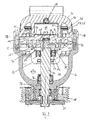
- the scroll compressor has a mechanical drive 10 in the form of a pulley. The pulley is connected in use to an electric motor or an internal combustion engine.
- the scroll compressor further includes a housing 30 having a housing cover 31 which closes the high pressure side of the compressor and is bolted to the housing 30.
- a housing intermediate wall 32 is arranged, which limits a suction chamber 33.
- a passage opening is formed, through which a drive shaft 11 extends.
- the arranged outside of the housing 30 shaft end is rotatably connected to a driver 35 which engages in the rotatably mounted on the housing 30 pulley, so that a torque can be transmitted to the drive shaft 11 of the pulley.
- the drive shaft 11 is rotatably mounted on the one hand in the housing bottom 34 and on the other hand in the housing intermediate wall 32.
- the sealing of the drive shaft 11 against the housing bottom 34 is effected by a first shaft seal 36 and against the housing intermediate wall 32 by a second shaft seal 37.
- the drive shaft 11 transmits the torque to a compressor unit, which is constructed as follows.
- the compressor unit comprises a movable displacement spiral 13 and a counter-spiral 14.
- the displacement spiral 13 and the counter-spiral 14 engage each other.
- the counter-spiral 14 is fixed in the circumferential direction and in the radial direction.
- the coupled with the drive shaft 11 movable displacement spiral 13 describes a circular path, so that in a conventional manner by this movement several gas pockets or gas chambers are generated, which migrate radially between the displacement spiral 13 and the counter-spiral 14.
- refrigerant vapor is sucked into the open outer gas chamber and compressed with the further spiral movement and the concomitant reduction of the gas chamber.
- the refrigerant vapor is increasingly compressed linearly from radially outward to radially inward direction and expelled in the center of the counter-spiral 14 into a pressure chamber 15.
- an eccentric bearing 12 is provided, which is connected to the drive shaft by an eccentric pin 38 (s. FIG. 2 ).
- the eccentric bearing 12 and the displacement spiral 13 are arranged eccentrically with respect to the counter-spiral 14.
- the gas chambers are separated from each other pressure-tight by conditioning the VerdrDeutscherspirale 13 on the counter-spiral 14.
- the radial contact pressure between the displacement spiral 13 and the counter-spiral 14 is adjusted by the eccentricity.
- a rotational movement of the displacement spiral is avoided by a plurality of guide pins 39, which, as in FIG. 2 shown, are mounted in the intermediate wall 32.
- the guide pins 39 engage in corresponding guide bores 40 which are formed in the displacement spiral 13.
- a counterweight 28 is connected, preferably in one piece, to the eccentric bearing 12 to compensate for the imbalance caused by the orbital motion of the displacer coil 13.
- FIGS. 1 . 2 shown scroll compressor is clutchless.
- the scroll compressor is switched on and off (digital circuit).
- the counter-spiral 14 in the axial direction ie in a direction parallel to the drive shaft 11 is alternately movable.
- the displacement spiral 13 is fixed in the axial direction.
- the counter-spiral 14 can be lifted from the displacement spiral 13 in the axial direction, as in the FIGS. 1 to 3 shown.
- a pressure equalizing gap 41 is created between the displacement spiral 13 and the counter-spiral 14, which connects the gas chambers, which are separated from each other in the radial direction, between the displacement spiral 13 and the counter-spiral 14.
- the sliding surface 42 is machined and seals against the counter-spiral 14.
- the rear wall 21 of the counter-spiral 14 forms the bottom of the pressure chamber 15.
- the counter-spiral 14 therefore closes directly with the pressure chamber 15.
- the rear wall 21 also has a flange 22, in particular an annular flange 22, which rests against the sliding surface 42 of the pressure chamber 15.
- the flange 22 serves as an axial guide of the counter-spiral 14 in the pressure chamber 15.
- On the outer circumference of the flange 22, a groove with a sealing means, for example a sealing ring 43 is formed.
- the pressure chamber 15 is bounded by a peripheral wall 44 which forms a stop 45 and limits the axial movement of the counter-spiral 14.
- the pressure chamber 15 is provided in the housing cover 31. As a result, the assembly of the axially movable counter-spiral 14 is simplified. In addition, it has a rotationally symmetrical cross section.
- axial force For the alternating movement of the counter-spiral 14 between the open position ( FIG. 3 ) and the closed position ( FIG. 4 ) opposite axial forces are required.
- the spring 16 may be formed, for example, as a plate spring.
- the spring 16 is in the closed position according to FIG. 4 biased and urges the counter-spiral 14 and the displacement spiral 13 apart.
- the spring 16 is disposed opposite to the pressure chamber 15.
- a central recess 46 is provided in the counter-spiral 14, in which the spring 16 is arranged.
- the spring 16 is supported on the displacement spiral 13.
- the bearing bush 26 is recessed for the eccentric bearing 12 in the positive displacement spiral 13.
- the bearing bush 26 dips into the counter-spiral 14 and protrudes into the counter-spiral 14.
- the bottom of the bearing bush 26, on which the spring 16 is supported, is at the same height as the inner edges of the turns of the displacer spiral 13. This is well in FIG. 3 to recognize (open position). In the closed position according to FIG. 4 Therefore, the bottom of the bearing bush 26 abuts against the counter-spiral 14 and seals the innermost gas chamber between the displacement spiral 13 and the counter-spiral 14.
- a piston 17, in particular an annular piston 17 is provided which is coaxial with the longitudinal axis of the counter-coil 14 slidably.
- annular piston 17 a plurality of arranged on the circumference of the counter-spiral 14 cylindrical piston can be provided.
- the annular piston 17 engages the rear wall 21 of the counter-spiral 14 and acts on it with a closing force which operates against the spring force of the spring 16.
- the piston 17 engages, as in the FIGS. 1 to 4 to recognize, in addition to the pressure chamber 15 to the counter-coil 14 at.
- the piston 17 is thus arranged outside the pressure chamber 15 or generally eccentrically.
- a simple outlet opening may be formed in the counter-spiral 14 (not shown).
- the annular piston 17 has a pressure ring 47, which is connected to a bottom 48 of the piston.
- the piston head 48 is axially displaceable and pressure-tight in an axial guide 18.
- the axial guide 18 is formed as an annular chamber.
- the annular chamber is connected to a supply connection 20c.
- the supply port 20c is connected to a 2/3-way valve, which in turn is connected to a high pressure port 20a and a suction pressure port 20b, so that the annular chamber can be acted upon alternately with high pressure or suction pressure.
- the counter-spiral 14 can be alternately moved back and forth between the open position or the closed position.
- the annular piston 17 operates substantially only against the spring force of the spring 16, because the pressure prevailing in the pressure chamber 15 and acting on the counter-spiral 14 pressure is at least partially compensated by the pressure acting between the counter-spiral 14 and the displacement spiral 13 during compression.
- only relatively small strokes are required to adjust the pressure equalizing gap 41. For example, stroke ranges of about 0.3 to 0.7 mm, in particular a stroke of about 0.5 mm.
- the power control takes place in the scroll compressor by switching on or off the compressor power, specifically by changing the frequency of the cyclic or alternating movement of the counter-spiral 14th
- the compressed gas collected in the pressure chamber 15 flows through an outlet 49 from the pressure chamber 15 into an oil separator 29, which in the present case is designed as a cyclone separator.
- the compressed gas flows through the oil separator 29 and a check valve 19 in the circuit of the air conditioner.
- the check valve 19, which prevents the compressed gas from flowing back into the scroll compressor which is switched off, is designed, for example, for pressure differences of 0.5 to 1 bar.
- a receiving space 24 also referred to as a backpressure space ( FIG. 1 ), in which a part of the counterweight 28 and the eccentric bearing 12 are arranged, fluidly connected to the high pressure side.
- the receiving space 24 is bounded by the rear wall 25 of the compressor spiral 13 and the housing intermediate wall 32.
- the receiving space 24 is fluid-tightly separated from the suction space 33 by the second shaft seal 37 described above.
- a sealing and sliding ring 52 is disposed between the displacement spiral 13 and the housing intermediate wall 32 and seals the receiving space 24 from the high pressure side.
- the sealing and sliding ring 52 is seated in an annular groove in the housing intermediate wall 32. Between the housing intermediate wall 32 and the displacement spiral 13, a gap is formed (not shown).
- the displacement spiral 13 is therefore not supported in the axial direction directly on the housing intermediate wall 32 but on the sealing and sliding ring 52 and slides on this.
- the sealing and sliding ring 52 protrudes from the annular groove and seals the gap.
- the gap can be about 0.2 mm to 0.5 mm wide.
- a line 50 connects the oil separator 29 with the receiving space 24. This extends through the housing cover 31, the counter-spiral 14 and the intermediate wall 32. Between the oil separator 29 and the receiving space 24, specifically between the counter-spiral 14 and the Housing cover 31, a pressure reducer 53 is arranged, which ensures that between the high pressure side and the receiving space 24, a pressure difference of about 10% -20% prevails. This ensures that in the closed position of the axial contact pressure between the displacement spiral 13 and the counter-spiral 14 and thus the axial tightness is increased.
- the pressure chamber 15 is encapsulated (s. FIG. 4 ).
- the pressure chamber 15 is free of installation.
- the pressure chamber may have an inner shell 51, in particular made of stainless steel or stainless steel.
- the inner shell 51 has a lower thermal conductivity than aluminum.
- the thermal insulation of the oil separator 29 reduces the heating of the refrigerant vapor on the suction side.
- the thermal insulation is carried out by an encapsulation, for example by an inner shell stainless steel or stainless steel surrounding the cyclone separator.
- the pressure reducer 53 is isolated by encapsulation with an inner shell of stainless steel or stainless steel.
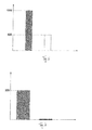
- FIG. 6 Figure 11 is a graph showing the mass inertia of the entire scroll compressor in kgmm 2 , with the prior art 1500 kgmm 2 left gray column representing the invention and the right white pillar the invention.
- the invention leads to an improvement of the mass inertia by a factor of 3. Since the displacement spiral 13 rotates in the off state, the inertia when connecting the scroll compressor is virtually zero. In contrast, the effective inertia when connecting a compressor of the prior art is up to 300 kgmm 2 .
- the resulting switch-on monument for the engine is in FIG.
Landscapes
- Engineering & Computer Science (AREA)
- Mechanical Engineering (AREA)
- General Engineering & Computer Science (AREA)
- Rotary Pumps (AREA)
- Applications Or Details Of Rotary Compressors (AREA)
- Air-Conditioning For Vehicles (AREA)
Priority Applications (4)
| Application Number | Priority Date | Filing Date | Title |
|---|---|---|---|
| EP13168737.8A EP2806165B1 (fr) | 2013-05-22 | 2013-05-22 | Compresseur à spirale et installation de climatisation de véhicule à CO2 dotée d'un compresseur à spirale |
| US14/282,540 US9291165B2 (en) | 2013-05-22 | 2014-05-20 | Scroll-type compressor and CO2 vehicle air conditioning system having a scroll-type compressor |
| JP2014104949A JP6425418B2 (ja) | 2013-05-22 | 2014-05-21 | スクロール型圧縮機およびスクロール型圧縮機を有するco2車両空調システム |
| CN201410216842.0A CN104179681B (zh) | 2013-05-22 | 2014-05-21 | 涡旋式压缩机以及具有涡旋式压缩机的co2车辆空调系统 |
Applications Claiming Priority (1)
| Application Number | Priority Date | Filing Date | Title |
|---|---|---|---|
| EP13168737.8A EP2806165B1 (fr) | 2013-05-22 | 2013-05-22 | Compresseur à spirale et installation de climatisation de véhicule à CO2 dotée d'un compresseur à spirale |
Publications (2)
| Publication Number | Publication Date |
|---|---|
| EP2806165A1 true EP2806165A1 (fr) | 2014-11-26 |
| EP2806165B1 EP2806165B1 (fr) | 2015-09-09 |
Family
ID=48520717
Family Applications (1)
| Application Number | Title | Priority Date | Filing Date |
|---|---|---|---|
| EP13168737.8A Active EP2806165B1 (fr) | 2013-05-22 | 2013-05-22 | Compresseur à spirale et installation de climatisation de véhicule à CO2 dotée d'un compresseur à spirale |
Country Status (4)
| Country | Link |
|---|---|
| US (1) | US9291165B2 (fr) |
| EP (1) | EP2806165B1 (fr) |
| JP (1) | JP6425418B2 (fr) |
| CN (1) | CN104179681B (fr) |
Cited By (2)
| Publication number | Priority date | Publication date | Assignee | Title |
|---|---|---|---|---|
| WO2017182516A1 (fr) * | 2016-04-19 | 2017-10-26 | OET GmbH | Dispositif séparateur pour séparer un fluide, en particulier un lubrifiant contenu dans un fluide de refroidissement |
| US20230113193A1 (en) * | 2020-06-17 | 2023-04-13 | Brose Fahrzeugteile SE & Co. Kommanditgesellschaft, Würzburg | Compressor module and electric-motor-driven refrigerant compressor |
Families Citing this family (8)
| Publication number | Priority date | Publication date | Assignee | Title |
|---|---|---|---|---|
| CN105402124B (zh) * | 2015-11-25 | 2018-10-23 | 珠海格力节能环保制冷技术研究中心有限公司 | 一种多级压缩机及空调系统 |
| DE102016113057B4 (de) * | 2016-07-15 | 2019-05-23 | Hanon Systems | Vorrichtung zum Verdichten eines gasförmigen Fluids mit einer Anordnung zum Separieren eines Steuermassenstroms sowie Verfahren zum Separieren des Steuermassenstroms |
| DE102017105175B3 (de) * | 2017-03-10 | 2018-08-23 | OET GmbH | Verdrängermaschine nach dem Spiralprinzip, Verfahren zum Betreiben einer Verdrängermaschine, Verdrängerspirale, Fahrzeugklimaanlage und Fahrzeug |
| DE102018124301A1 (de) * | 2017-11-01 | 2019-05-02 | Hanon Systems | Scrollverdichter |
| CN112585356B (zh) * | 2018-08-24 | 2023-06-27 | 博泽沃尔兹堡汽车零部件欧洲两合公司 | 压缩机模块以及电动制冷压缩机 |
| US11286931B2 (en) * | 2019-08-27 | 2022-03-29 | Samsung Electronics Co., Ltd. | Scroll compressor having a shaft support portion including a closing portion |
| DE102020134469A1 (de) * | 2020-12-21 | 2022-06-23 | OET GmbH | Scrollverdichter zur Erzeugung von ölfreier Druckluft |
| CN115450908B (zh) * | 2022-09-21 | 2024-11-29 | 珠海格力电器股份有限公司 | 静盘组件、涡旋压缩机、新能源车 |
Citations (5)
| Publication number | Priority date | Publication date | Assignee | Title |
|---|---|---|---|---|
| JPS6263189A (ja) * | 1985-09-17 | 1987-03-19 | Nippon Soken Inc | スクロ−ル型圧縮機 |
| EP1087142A2 (fr) * | 1999-09-21 | 2001-03-28 | Copeland Corporation | Compresseur à spirales à commande de capacite |
| US6273692B1 (en) | 1999-06-29 | 2001-08-14 | Sanden Corporation | Scroll-type compressor |
| US20020081224A1 (en) | 2000-12-22 | 2002-06-27 | Motohiko Ueda | Scroll-type compressor |
| JP2006144635A (ja) | 2004-11-18 | 2006-06-08 | Denso Corp | スクロール型圧縮機 |
Family Cites Families (25)
| Publication number | Priority date | Publication date | Assignee | Title |
|---|---|---|---|---|
| FR1482910A (fr) * | 1966-03-23 | 1967-06-02 | Pompe volumétrique | |
| US3817664A (en) * | 1972-12-11 | 1974-06-18 | J Bennett | Rotary fluid pump or motor with intermeshed spiral walls |
| US3874827A (en) * | 1973-10-23 | 1975-04-01 | Niels O Young | Positive displacement scroll apparatus with axially radially compliant scroll member |
| JPS581278B2 (ja) * | 1980-04-05 | 1983-01-10 | サンデン株式会社 | スクロ−ル型圧縮機 |
| US4610610A (en) * | 1984-08-16 | 1986-09-09 | Sundstrand Corporation | Unloading of scroll compressors |
| US4927339A (en) * | 1988-10-14 | 1990-05-22 | American Standard Inc. | Rotating scroll apparatus with axially biased scroll members |
| US5199280A (en) * | 1991-11-25 | 1993-04-06 | American Standard Inc. | Co-rotational scroll compressor supercharger device |
| JP3170111B2 (ja) | 1993-09-24 | 2001-05-28 | 株式会社日立製作所 | スクロール圧縮機 |
| US5741120A (en) * | 1995-06-07 | 1998-04-21 | Copeland Corporation | Capacity modulated scroll machine |
| US6047557A (en) * | 1995-06-07 | 2000-04-11 | Copeland Corporation | Adaptive control for a refrigeration system using pulse width modulated duty cycle scroll compressor |
| JP2002161875A (ja) * | 2000-11-27 | 2002-06-07 | Matsushita Electric Works Ltd | スクロールポンプ |
| JP2003227476A (ja) | 2002-02-05 | 2003-08-15 | Matsushita Electric Ind Co Ltd | 空気供給装置 |
| US6758659B2 (en) | 2002-04-11 | 2004-07-06 | Shimao Ni | Scroll type fluid displacement apparatus with fully compliant floating scrolls |
| US7265080B2 (en) | 2002-06-12 | 2007-09-04 | Nsk Ltd. | Rolling bearing, rolling bearing for fuel cell, compressor for fuel cell system and fuel cell system |
| CN2589697Y (zh) * | 2002-12-30 | 2003-12-03 | 财团法人工业技术研究院 | 涡卷式压缩机的负载调节装置 |
| JP2005023817A (ja) | 2003-07-01 | 2005-01-27 | Matsushita Electric Ind Co Ltd | スクロール圧縮機およびスクロールラップの加工方法 |
| CN2714847Y (zh) * | 2004-04-27 | 2005-08-03 | 瑞智精密股份有限公司 | 涡卷压缩机的背压机构 |
| JP2006200488A (ja) * | 2005-01-21 | 2006-08-03 | Sanden Corp | スクロール型圧縮機 |
| EP2853746B1 (fr) | 2006-03-03 | 2017-07-19 | Daikin Industries, Ltd. | Compresseur et son procédé de fabrication |
| JP2008121490A (ja) * | 2006-11-10 | 2008-05-29 | Daikin Ind Ltd | 回転式圧縮機 |
| US7771178B2 (en) * | 2006-12-22 | 2010-08-10 | Emerson Climate Technologies, Inc. | Vapor injection system for a scroll compressor |
| DE102008013784B4 (de) | 2007-03-15 | 2017-03-23 | Denso Corporation | Kompressor |
| US7611344B2 (en) | 2007-10-15 | 2009-11-03 | Scroll Laboratories, Inc. | Sealing tabs on orbiting scroll |
| WO2012144067A1 (fr) * | 2011-04-22 | 2012-10-26 | 株式会社日立製作所 | Compresseur à volutes |
| JP2012237251A (ja) * | 2011-05-12 | 2012-12-06 | Mitsubishi Heavy Ind Ltd | スクロール型流体機械 |
-
2013
- 2013-05-22 EP EP13168737.8A patent/EP2806165B1/fr active Active
-
2014
- 2014-05-20 US US14/282,540 patent/US9291165B2/en not_active Expired - Fee Related
- 2014-05-21 CN CN201410216842.0A patent/CN104179681B/zh not_active Expired - Fee Related
- 2014-05-21 JP JP2014104949A patent/JP6425418B2/ja not_active Expired - Fee Related
Patent Citations (5)
| Publication number | Priority date | Publication date | Assignee | Title |
|---|---|---|---|---|
| JPS6263189A (ja) * | 1985-09-17 | 1987-03-19 | Nippon Soken Inc | スクロ−ル型圧縮機 |
| US6273692B1 (en) | 1999-06-29 | 2001-08-14 | Sanden Corporation | Scroll-type compressor |
| EP1087142A2 (fr) * | 1999-09-21 | 2001-03-28 | Copeland Corporation | Compresseur à spirales à commande de capacite |
| US20020081224A1 (en) | 2000-12-22 | 2002-06-27 | Motohiko Ueda | Scroll-type compressor |
| JP2006144635A (ja) | 2004-11-18 | 2006-06-08 | Denso Corp | スクロール型圧縮機 |
Cited By (6)
| Publication number | Priority date | Publication date | Assignee | Title |
|---|---|---|---|---|
| WO2017182516A1 (fr) * | 2016-04-19 | 2017-10-26 | OET GmbH | Dispositif séparateur pour séparer un fluide, en particulier un lubrifiant contenu dans un fluide de refroidissement |
| CN109072920A (zh) * | 2016-04-19 | 2018-12-21 | 欧伊特股份有限公司 | 从冷却剂流体中分离流体,特别是润滑剂的分离器装置 |
| CN109072920B (zh) * | 2016-04-19 | 2020-05-22 | 欧伊特股份有限公司 | 从冷却剂流体中分离流体,特别是润滑剂的分离器装置 |
| US10935027B2 (en) | 2016-04-19 | 2021-03-02 | OET GmbH | Separator device for separating a fluid, in particular a lubricant, from a coolant |
| US20230113193A1 (en) * | 2020-06-17 | 2023-04-13 | Brose Fahrzeugteile SE & Co. Kommanditgesellschaft, Würzburg | Compressor module and electric-motor-driven refrigerant compressor |
| US12292052B2 (en) * | 2020-06-17 | 2025-05-06 | Brose Fahrzeugteile SE & Co. Kommanditgesellschaft, Würzburg | Compressor module and electric-motor-driven refrigerant compressor |
Also Published As
| Publication number | Publication date |
|---|---|
| EP2806165B1 (fr) | 2015-09-09 |
| US9291165B2 (en) | 2016-03-22 |
| CN104179681A (zh) | 2014-12-03 |
| JP2014228003A (ja) | 2014-12-08 |
| CN104179681B (zh) | 2018-03-16 |
| JP6425418B2 (ja) | 2018-11-21 |
| US20140348682A1 (en) | 2014-11-27 |
Similar Documents
| Publication | Publication Date | Title |
|---|---|---|
| EP2806165B1 (fr) | Compresseur à spirale et installation de climatisation de véhicule à CO2 dotée d'un compresseur à spirale | |
| EP2806164B1 (fr) | Compresseur à spirale et installation de climatisation de véhicule à CO2 dotée d'un compresseur à spirale | |
| DE60221316T2 (de) | Diagnosesystem für hermetische Spiralverdichter | |
| DE69928055T2 (de) | Liefermengenregelung eines Verdichters | |
| DE602004009026T2 (de) | Spiralverdichter | |
| EP2584200B1 (fr) | Valve d'entrée de gaz pour un compresseur, compresseur équipé d'une telle valve d'entrée de gaz et procédé de fonctionnement d'un compresseur équipé d'une telle valve d'entrée de gaz | |
| EP3545195B1 (fr) | Machine à déplacement positif selon le principe de la spirale, procédé de fonctionnement d'une machine à déplacement positif, spirale à déplacement positif, installation de climatisation de véhicule et véhicule | |
| DE19650108A1 (de) | Taumelscheiben-Kompressor | |
| DE3923304C2 (fr) | ||
| DE102020203491B4 (de) | Scroll-Verdichter | |
| DE4200305A1 (de) | Regelbare fluegelzellenpumpe in kompakter bauweise | |
| DE102020210453B4 (de) | Scrollverdichter eines elektrischen Kältemittelantriebs | |
| DE69408713T2 (de) | Rotationsgaskompressor | |
| EP1297256B1 (fr) | Dispositif de securite pour compresseur de conditionnement d'air | |
| EP1240433B1 (fr) | Pompe à vide à compression sèche comportant un dispositif de ballast à gaz | |
| DE19722688C2 (de) | Kompressor | |
| DE602005000066T2 (de) | Verdichter | |
| DE102016217358A1 (de) | Scrollverdichter | |
| DE10225416B4 (de) | Drehvorrichtung | |
| DE102016203587A1 (de) | Taumelscheibenverdichter mit veränderlicher Verdrängung | |
| DE19919141A1 (de) | Elektromotorisch angetriebener Kompressor | |
| DE102017102645B4 (de) | Kältemittel-Scrollverdichter für die Verwendung innerhalb einer Wärmepumpe | |
| DE102019208680A1 (de) | Verdrängermaschine nach dem Spiralprinzip, insbesondere Scrollverdichter für eine Fahrzeugklimaanlage | |
| DE112015003978T5 (de) | Schnecken-Fluidmaschine | |
| EP2499366A1 (fr) | Compresseur de climatisation pour un véhicule et véhicule |
Legal Events
| Date | Code | Title | Description |
|---|---|---|---|
| PUAI | Public reference made under article 153(3) epc to a published international application that has entered the european phase |
Free format text: ORIGINAL CODE: 0009012 |
|
| 17P | Request for examination filed |
Effective date: 20131126 |
|
| AK | Designated contracting states |
Kind code of ref document: A1 Designated state(s): AL AT BE BG CH CY CZ DE DK EE ES FI FR GB GR HR HU IE IS IT LI LT LU LV MC MK MT NL NO PL PT RO RS SE SI SK SM TR |
|
| AX | Request for extension of the european patent |
Extension state: BA ME |
|
| RIC1 | Information provided on ipc code assigned before grant |
Ipc: F04C 18/02 20060101AFI20150210BHEP |
|
| GRAP | Despatch of communication of intention to grant a patent |
Free format text: ORIGINAL CODE: EPIDOSNIGR1 |
|
| INTG | Intention to grant announced |
Effective date: 20150320 |
|
| GRAS | Grant fee paid |
Free format text: ORIGINAL CODE: EPIDOSNIGR3 |
|
| GRAA | (expected) grant |
Free format text: ORIGINAL CODE: 0009210 |
|
| AK | Designated contracting states |
Kind code of ref document: B1 Designated state(s): AL AT BE BG CH CY CZ DE DK EE ES FI FR GB GR HR HU IE IS IT LI LT LU LV MC MK MT NL NO PL PT RO RS SE SI SK SM TR |
|
| REG | Reference to a national code |
Ref country code: GB Ref legal event code: FG4D Free format text: NOT ENGLISH |
|
| REG | Reference to a national code |
Ref country code: AT Ref legal event code: REF Ref document number: 748362 Country of ref document: AT Kind code of ref document: T Effective date: 20150915 Ref country code: CH Ref legal event code: EP |
|
| REG | Reference to a national code |
Ref country code: IE Ref legal event code: FG4D Free format text: LANGUAGE OF EP DOCUMENT: GERMAN |
|
| REG | Reference to a national code |
Ref country code: DE Ref legal event code: R096 Ref document number: 502013001119 Country of ref document: DE |
|
| REG | Reference to a national code |
Ref country code: NL Ref legal event code: MP Effective date: 20150909 |
|
| PG25 | Lapsed in a contracting state [announced via postgrant information from national office to epo] |
Ref country code: LT Free format text: LAPSE BECAUSE OF FAILURE TO SUBMIT A TRANSLATION OF THE DESCRIPTION OR TO PAY THE FEE WITHIN THE PRESCRIBED TIME-LIMIT Effective date: 20150909 Ref country code: GR Free format text: LAPSE BECAUSE OF FAILURE TO SUBMIT A TRANSLATION OF THE DESCRIPTION OR TO PAY THE FEE WITHIN THE PRESCRIBED TIME-LIMIT Effective date: 20151210 Ref country code: LV Free format text: LAPSE BECAUSE OF FAILURE TO SUBMIT A TRANSLATION OF THE DESCRIPTION OR TO PAY THE FEE WITHIN THE PRESCRIBED TIME-LIMIT Effective date: 20150909 Ref country code: FI Free format text: LAPSE BECAUSE OF FAILURE TO SUBMIT A TRANSLATION OF THE DESCRIPTION OR TO PAY THE FEE WITHIN THE PRESCRIBED TIME-LIMIT Effective date: 20150909 Ref country code: NO Free format text: LAPSE BECAUSE OF FAILURE TO SUBMIT A TRANSLATION OF THE DESCRIPTION OR TO PAY THE FEE WITHIN THE PRESCRIBED TIME-LIMIT Effective date: 20151209 |
|
| REG | Reference to a national code |
Ref country code: LT Ref legal event code: MG4D |
|
| PG25 | Lapsed in a contracting state [announced via postgrant information from national office to epo] |
Ref country code: HR Free format text: LAPSE BECAUSE OF FAILURE TO SUBMIT A TRANSLATION OF THE DESCRIPTION OR TO PAY THE FEE WITHIN THE PRESCRIBED TIME-LIMIT Effective date: 20150909 Ref country code: ES Free format text: LAPSE BECAUSE OF FAILURE TO SUBMIT A TRANSLATION OF THE DESCRIPTION OR TO PAY THE FEE WITHIN THE PRESCRIBED TIME-LIMIT Effective date: 20150909 Ref country code: SE Free format text: LAPSE BECAUSE OF FAILURE TO SUBMIT A TRANSLATION OF THE DESCRIPTION OR TO PAY THE FEE WITHIN THE PRESCRIBED TIME-LIMIT Effective date: 20150909 Ref country code: RS Free format text: LAPSE BECAUSE OF FAILURE TO SUBMIT A TRANSLATION OF THE DESCRIPTION OR TO PAY THE FEE WITHIN THE PRESCRIBED TIME-LIMIT Effective date: 20150909 |
|
| PG25 | Lapsed in a contracting state [announced via postgrant information from national office to epo] |
Ref country code: NL Free format text: LAPSE BECAUSE OF FAILURE TO SUBMIT A TRANSLATION OF THE DESCRIPTION OR TO PAY THE FEE WITHIN THE PRESCRIBED TIME-LIMIT Effective date: 20150909 |
|
| PG25 | Lapsed in a contracting state [announced via postgrant information from national office to epo] |
Ref country code: EE Free format text: LAPSE BECAUSE OF FAILURE TO SUBMIT A TRANSLATION OF THE DESCRIPTION OR TO PAY THE FEE WITHIN THE PRESCRIBED TIME-LIMIT Effective date: 20150909 Ref country code: SK Free format text: LAPSE BECAUSE OF FAILURE TO SUBMIT A TRANSLATION OF THE DESCRIPTION OR TO PAY THE FEE WITHIN THE PRESCRIBED TIME-LIMIT Effective date: 20150909 Ref country code: IS Free format text: LAPSE BECAUSE OF FAILURE TO SUBMIT A TRANSLATION OF THE DESCRIPTION OR TO PAY THE FEE WITHIN THE PRESCRIBED TIME-LIMIT Effective date: 20160109 Ref country code: CZ Free format text: LAPSE BECAUSE OF FAILURE TO SUBMIT A TRANSLATION OF THE DESCRIPTION OR TO PAY THE FEE WITHIN THE PRESCRIBED TIME-LIMIT Effective date: 20150909 |
|
| PG25 | Lapsed in a contracting state [announced via postgrant information from national office to epo] |
Ref country code: PT Free format text: LAPSE BECAUSE OF FAILURE TO SUBMIT A TRANSLATION OF THE DESCRIPTION OR TO PAY THE FEE WITHIN THE PRESCRIBED TIME-LIMIT Effective date: 20160111 Ref country code: PL Free format text: LAPSE BECAUSE OF FAILURE TO SUBMIT A TRANSLATION OF THE DESCRIPTION OR TO PAY THE FEE WITHIN THE PRESCRIBED TIME-LIMIT Effective date: 20150909 Ref country code: RO Free format text: LAPSE BECAUSE OF FAILURE TO SUBMIT A TRANSLATION OF THE DESCRIPTION OR TO PAY THE FEE WITHIN THE PRESCRIBED TIME-LIMIT Effective date: 20150909 |
|
| REG | Reference to a national code |
Ref country code: FR Ref legal event code: PLFP Year of fee payment: 4 |
|
| REG | Reference to a national code |
Ref country code: DE Ref legal event code: R097 Ref document number: 502013001119 Country of ref document: DE |
|
| PLBE | No opposition filed within time limit |
Free format text: ORIGINAL CODE: 0009261 |
|
| STAA | Information on the status of an ep patent application or granted ep patent |
Free format text: STATUS: NO OPPOSITION FILED WITHIN TIME LIMIT |
|
| 26N | No opposition filed |
Effective date: 20160610 |
|
| PG25 | Lapsed in a contracting state [announced via postgrant information from national office to epo] |
Ref country code: BE Free format text: LAPSE BECAUSE OF NON-PAYMENT OF DUE FEES Effective date: 20160531 Ref country code: DK Free format text: LAPSE BECAUSE OF FAILURE TO SUBMIT A TRANSLATION OF THE DESCRIPTION OR TO PAY THE FEE WITHIN THE PRESCRIBED TIME-LIMIT Effective date: 20150909 Ref country code: SI Free format text: LAPSE BECAUSE OF FAILURE TO SUBMIT A TRANSLATION OF THE DESCRIPTION OR TO PAY THE FEE WITHIN THE PRESCRIBED TIME-LIMIT Effective date: 20150909 |
|
| PG25 | Lapsed in a contracting state [announced via postgrant information from national office to epo] |
Ref country code: LU Free format text: LAPSE BECAUSE OF FAILURE TO SUBMIT A TRANSLATION OF THE DESCRIPTION OR TO PAY THE FEE WITHIN THE PRESCRIBED TIME-LIMIT Effective date: 20160522 |
|
| REG | Reference to a national code |
Ref country code: CH Ref legal event code: PL |
|
| PG25 | Lapsed in a contracting state [announced via postgrant information from national office to epo] |
Ref country code: CH Free format text: LAPSE BECAUSE OF NON-PAYMENT OF DUE FEES Effective date: 20160531 Ref country code: LI Free format text: LAPSE BECAUSE OF NON-PAYMENT OF DUE FEES Effective date: 20160531 |
|
| REG | Reference to a national code |
Ref country code: IE Ref legal event code: MM4A |
|
| REG | Reference to a national code |
Ref country code: FR Ref legal event code: PLFP Year of fee payment: 5 |
|
| PG25 | Lapsed in a contracting state [announced via postgrant information from national office to epo] |
Ref country code: IE Free format text: LAPSE BECAUSE OF NON-PAYMENT OF DUE FEES Effective date: 20160522 |
|
| REG | Reference to a national code |
Ref country code: FR Ref legal event code: PLFP Year of fee payment: 6 |
|
| PG25 | Lapsed in a contracting state [announced via postgrant information from national office to epo] |
Ref country code: SM Free format text: LAPSE BECAUSE OF FAILURE TO SUBMIT A TRANSLATION OF THE DESCRIPTION OR TO PAY THE FEE WITHIN THE PRESCRIBED TIME-LIMIT Effective date: 20150909 Ref country code: HU Free format text: LAPSE BECAUSE OF FAILURE TO SUBMIT A TRANSLATION OF THE DESCRIPTION OR TO PAY THE FEE WITHIN THE PRESCRIBED TIME-LIMIT; INVALID AB INITIO Effective date: 20130522 |
|
| PG25 | Lapsed in a contracting state [announced via postgrant information from national office to epo] |
Ref country code: CY Free format text: LAPSE BECAUSE OF FAILURE TO SUBMIT A TRANSLATION OF THE DESCRIPTION OR TO PAY THE FEE WITHIN THE PRESCRIBED TIME-LIMIT Effective date: 20150909 Ref country code: MT Free format text: LAPSE BECAUSE OF FAILURE TO SUBMIT A TRANSLATION OF THE DESCRIPTION OR TO PAY THE FEE WITHIN THE PRESCRIBED TIME-LIMIT Effective date: 20150909 Ref country code: MC Free format text: LAPSE BECAUSE OF FAILURE TO SUBMIT A TRANSLATION OF THE DESCRIPTION OR TO PAY THE FEE WITHIN THE PRESCRIBED TIME-LIMIT Effective date: 20150909 Ref country code: MK Free format text: LAPSE BECAUSE OF FAILURE TO SUBMIT A TRANSLATION OF THE DESCRIPTION OR TO PAY THE FEE WITHIN THE PRESCRIBED TIME-LIMIT Effective date: 20150909 |
|
| PG25 | Lapsed in a contracting state [announced via postgrant information from national office to epo] |
Ref country code: BG Free format text: LAPSE BECAUSE OF FAILURE TO SUBMIT A TRANSLATION OF THE DESCRIPTION OR TO PAY THE FEE WITHIN THE PRESCRIBED TIME-LIMIT Effective date: 20150909 |
|
| PG25 | Lapsed in a contracting state [announced via postgrant information from national office to epo] |
Ref country code: AL Free format text: LAPSE BECAUSE OF FAILURE TO SUBMIT A TRANSLATION OF THE DESCRIPTION OR TO PAY THE FEE WITHIN THE PRESCRIBED TIME-LIMIT Effective date: 20150909 |
|
| REG | Reference to a national code |
Ref country code: AT Ref legal event code: MM01 Ref document number: 748362 Country of ref document: AT Kind code of ref document: T Effective date: 20180522 |
|
| PG25 | Lapsed in a contracting state [announced via postgrant information from national office to epo] |
Ref country code: AT Free format text: LAPSE BECAUSE OF NON-PAYMENT OF DUE FEES Effective date: 20180522 |
|
| PGFP | Annual fee paid to national office [announced via postgrant information from national office to epo] |
Ref country code: FR Payment date: 20200528 Year of fee payment: 8 Ref country code: TR Payment date: 20200511 Year of fee payment: 8 |
|
| PGFP | Annual fee paid to national office [announced via postgrant information from national office to epo] |
Ref country code: IT Payment date: 20200522 Year of fee payment: 8 Ref country code: GB Payment date: 20200528 Year of fee payment: 8 |
|
| GBPC | Gb: european patent ceased through non-payment of renewal fee |
Effective date: 20210522 |
|
| PG25 | Lapsed in a contracting state [announced via postgrant information from national office to epo] |
Ref country code: GB Free format text: LAPSE BECAUSE OF NON-PAYMENT OF DUE FEES Effective date: 20210522 |
|
| PG25 | Lapsed in a contracting state [announced via postgrant information from national office to epo] |
Ref country code: FR Free format text: LAPSE BECAUSE OF NON-PAYMENT OF DUE FEES Effective date: 20210531 |
|
| PG25 | Lapsed in a contracting state [announced via postgrant information from national office to epo] |
Ref country code: IT Free format text: LAPSE BECAUSE OF NON-PAYMENT OF DUE FEES Effective date: 20200522 |
|
| PGFP | Annual fee paid to national office [announced via postgrant information from national office to epo] |
Ref country code: DE Payment date: 20250528 Year of fee payment: 13 |
|
| PG25 | Lapsed in a contracting state [announced via postgrant information from national office to epo] |
Ref country code: IT Free format text: LAPSE BECAUSE OF NON-PAYMENT OF DUE FEES Effective date: 20210522 |