EP2807909B1 - Schaltschrank mit gehäuse - Google Patents
Schaltschrank mit gehäuse Download PDFInfo
- Publication number
- EP2807909B1 EP2807909B1 EP13703989.7A EP13703989A EP2807909B1 EP 2807909 B1 EP2807909 B1 EP 2807909B1 EP 13703989 A EP13703989 A EP 13703989A EP 2807909 B1 EP2807909 B1 EP 2807909B1
- Authority
- EP
- European Patent Office
- Prior art keywords
- mounting plate
- air
- heat sink
- housing
- cooling
- Prior art date
- Legal status (The legal status is an assumption and is not a legal conclusion. Google has not performed a legal analysis and makes no representation as to the accuracy of the status listed.)
- Active
Links
Images



Classifications
-
- H—ELECTRICITY
- H05—ELECTRIC TECHNIQUES NOT OTHERWISE PROVIDED FOR
- H05K—PRINTED CIRCUITS; CASINGS OR CONSTRUCTIONAL DETAILS OF ELECTRIC APPARATUS; MANUFACTURE OF ASSEMBLAGES OF ELECTRICAL COMPONENTS
- H05K7/00—Constructional details common to different types of electric apparatus
- H05K7/20—Modifications to facilitate cooling, ventilating, or heating
- H05K7/2089—Modifications to facilitate cooling, ventilating, or heating for power electronics, e.g. for inverters for controlling motor
- H05K7/20909—Forced ventilation, e.g. on heat dissipaters coupled to components
- H05K7/20918—Forced ventilation, e.g. on heat dissipaters coupled to components the components being isolated from air flow, e.g. hollow heat sinks, wind tunnels or funnels
-
- H—ELECTRICITY
- H05—ELECTRIC TECHNIQUES NOT OTHERWISE PROVIDED FOR
- H05K—PRINTED CIRCUITS; CASINGS OR CONSTRUCTIONAL DETAILS OF ELECTRIC APPARATUS; MANUFACTURE OF ASSEMBLAGES OF ELECTRICAL COMPONENTS
- H05K7/00—Constructional details common to different types of electric apparatus
- H05K7/20—Modifications to facilitate cooling, ventilating, or heating
- H05K7/20536—Modifications to facilitate cooling, ventilating, or heating for racks or cabinets of standardised dimensions, e.g. electronic racks for aircraft or telecommunication equipment
- H05K7/20554—Forced ventilation of a gaseous coolant
- H05K7/20572—Forced ventilation of a gaseous coolant within cabinets for removing heat from sub-racks, e.g. plenum
-
- H—ELECTRICITY
- H05—ELECTRIC TECHNIQUES NOT OTHERWISE PROVIDED FOR
- H05K—PRINTED CIRCUITS; CASINGS OR CONSTRUCTIONAL DETAILS OF ELECTRIC APPARATUS; MANUFACTURE OF ASSEMBLAGES OF ELECTRICAL COMPONENTS
- H05K7/00—Constructional details common to different types of electric apparatus
- H05K7/20—Modifications to facilitate cooling, ventilating, or heating
- H05K7/20709—Modifications to facilitate cooling, ventilating, or heating for server racks or cabinets; for data centers, e.g. 19-inch computer racks
- H05K7/20718—Forced ventilation of a gaseous coolant
- H05K7/20736—Forced ventilation of a gaseous coolant within cabinets for removing heat from server blades
Definitions
- the invention relates to a control cabinet with housing.
- the invention is therefore based on the object of providing improved heat dissipation.
- the object is achieved in the device according to the features specified in claim 1.
- the advantage here is that a large heat dissipation surface can be achieved through the large number of modules and a large amount of heat dissipation can also be achieved through the central ventilation.
- the central ventilation is supplied from an interior area of the device surrounded by the housing.
- the advantage here is that a pressure-equalizing interior area is used to supply several central ventilation systems, which may have different suction strengths.
- fans can be used in the modules, the performance of which depends on the required or predicted performance varies.
- the cooling air flow depends on the performance of the fan.
- the large interior area of the device makes it possible to create a pressure buffer.
- the housing has a recess through which the interior can be supplied with a cooling medium flow, in particular, a fan grille is arranged in the recess of the housing.
- a fan grille is arranged in the recess of the housing.
- the advantage here is that only a single recess needs to be protected by a fan grille.
- the fan grille can also be designed with such a fine mesh that the cooling air flow can be filtered, i.e. correspondingly large dirt particles can be filtered out of the cooling air flow.
- a mounting plate is arranged within the housing between the interior and the collecting duct, in particular, the interior area is separated from the collecting duct by means of a mounting plate.
- the modules are connected to the mounting plate, in particular are held by the mounting plate, in particular are screwed together.
- the advantage here is that the mounting plate separating the cooler from the warmer areas also functions as a mechanical holding device.
- the air guide part is manufactured as a continuous cast part.
- the advantage here is that it enables cost-effective production, particularly from aluminum, which has a low thermal resistance.
- the mounting plate has a recess that runs through the mounting plate and is associated with the respective module, in particular its central ventilation and/or its cooling channel, in particular for the flow of the cooling medium.
- the interior area is limited by at least the mounting plate, the housing and the fan grille and/or the collecting duct is limited by at least the mounting plate and the housing.
- the advantage here is that the interior area with cooler air can be easily separated from the collecting duct with warmer air.
- the module has a heat sink with a continuous cavity, which functions as a cooling channel, in particular, the heat sink is designed as a continuous cast part.
- the heat sink can be made in one piece or in multiple pieces and can therefore be made in one piece or in two pieces depending on the respective requirements.
- a large outer surface can be achieved around the cooling channel, so that effective heat dissipation can be achieved.
- one or more heat-generating components are connected to a respective outer surface section in a heat-conducting manner.
- the advantage here is that a large outer surface can be cooled by the central ventilation.
- the outer surface can be assembled from several flat surface sections so that flat circuit boards can be assigned to these sections and the heat-generating components arranged thereon can be brought into heat-conducting contact with the respective outer surface section.
- a heat-generating component is mounted on a printed circuit board, in particular with its electrical connection elements being soldered to a conductor track section,
- the circuit board is connected to the heat sink by means of a holding device.
- the holding device can be arranged on the side of the circuit board facing away from the heat sink and only screws, for example, lead through the circuit board to the heat sink so that the circuit board including components can be pressed towards the heat sink.
- the holding device is an insulating means on the circuit board, which is pressed onto the circuit board by a holding plate, in particular by a metallic holding plate, in particular, the retaining plate is screwed to the heat sink or pressed onto the insulating means by a spring element screwed to the heat sink.
- the printed circuit board is an arrangement of printed circuit boards connected by means of flexible areas, in particular, the arrangement at least partially surrounds the heat sink in the circumferential direction of the cooling channel.
- At least one air guide part is arranged on the heat sink, in particular, wherein a first air guide part comprises a fan and an air guide part spaced from the first air guide part by means of the heat sink serves to hold the heat sink on the mounting plate, in particular wherein the further air guide part is arranged between the heat sink and the mounting plate.
- a first air guide part comprises a fan and an air guide part spaced from the first air guide part by means of the heat sink serves to hold the heat sink on the mounting plate, in particular wherein the further air guide part is arranged between the heat sink and the mounting plate.
- the module has a central ventilation system for dissipating the heat generated by the heat-generating components.
- a heat sink 1 is provided, which is manufactured as a single-piece or multi-piece continuous casting part.
- This heat sink 1 is hollow and has cooling fins 30 protruding into the cavity.
- the cavity surface is enlarged and the heat transfer resistance from the heat sink 1 to the cooling medium flowing through the cavity, in particular cooling air, is reduced.
- the heat sink 1 is a continuously cast part, in particular an aluminum continuously cast part, the cavity is continuous and the cooling fins 30 and the cavity run in the continuous casting direction.
- the heat sink is designed as a cuboid and thus has four approximately flat side surfaces.
- at least two side surfaces in particular the two diametrically opposed Side surfaces, contact surfaces 2, which are finely machined, in particular milled and/or ground and/or sandblasted or the like.
- the components can thus be pressed onto the contact surface, in particular with thermal paste arranged between them, and good heat transfer can be achieved.
- a ferrite part 31 is pressed or otherwise connected to the other two side surfaces, so that the heat generated by a winding 32 can be conducted to the heat sink 1 via the ferrite 31.
- the ferrite part 31 is used as the coil core of the winding 32, so that the magnetic field generated by the winding 32 is bundled and conducted by the ferrite part 31.
- the winding is used as an inductance of a DC-DC converter, i.e. as a booster choke of a DC-DC booster.
- the cavity of the heat sink 1 opens at its first opening in the direction of continuous casting into an air guide part 3, which is made of plastic and is attached to the heat sink 1.
- the air guide part 3 has a flange at its end area facing away from the heat sink 1, with which it can be screwed onto a mounting plate 42.
- the mounting plate 42 has a recess so that the cooling medium, after flowing through the heat sink 1 and the air guide part 3, flows through the recess of the mounting plate 42 and into a Figure 5 shown air duct 50.
- the cavity of the heat sink 1 opens into an air guide part 4 in which a fan is arranged.
- the ferrite parts 31 are preferably screw-connected to the heat sink 1 and thus pressed against it or pressed against the heat sink 1 by a part screw-connected to the heat sink 1.
- the heat-generating components are mounted on one of the circuit boards (23, 25). These circuit boards (23, 25) are part of a flexible circuit board arrangement.
- the circuit boards (23, 24, 25) are connected via intermediate flexible areas 26.
- the carrier material in particular epoxy resin, is mechanically removed from a large circuit board in a respective partial area. removed, in particular milled out, or chemically removed.
- these sub-areas which now function as flexible areas 26, only the metallic conductor tracks and a respective film supporting them remain.
- the circuit board arrangement is thus wound around the heat sink 1 so that the heat-generating components can be pressed onto the contact surfaces 2 of the oppositely arranged outer surfaces of the heat sink 1.
- the inductance of a DC-DC booster is arranged on the circuit board 24 arranged between the circuit boards (23, 25), the coil core of which, in particular ferrite part 31, is connected in a heat-conducting manner, in particular pressed, to the heat sink 1.
- heat-generating components of the electronic circuit.
- power semiconductor switches and coil cores of the windings 32 are mentioned as examples of heat-generating components.
- These heat-generating components are therefore each arranged on the side of the respective circuit board (23, 24, 25) facing the heat sink 1.
- the fan can be used to drive a flow of cooling air, so that heat dissipation can be carried out very effectively. But even without a fan, a convectively driven flow is present and causes heat dissipation.
- a control cabinet 40 several as shown in the Figures 1 to 3
- the previously described modules can be arranged on a mounting plate 42, wherein the mounting plate 42 has a respective continuous recess for central ventilation of the respective modules.
- a respective cooling channel leading through the air guide parts (3, 4) and the cavity of the heat sink 1 as well as through the recess in the mounting plate 42 opens into the in the control cabinet 40 vertically upwardly leading air duct 50, which opens into a deflection part 41.
- the air duct 50 runs inside the control cabinet 40.
- the deflection part arranged on the top of the control cabinet 40 has an opening directed towards the air duct 50, which is deflected from the vertical to the horizontal direction on a horizontally running base plate arranged on the top of the deflection part 41.
- the deflection part 41 is preferably designed as a continuous cast part, so that cooling fins are formed on the base plate of the deflection part 41. In this way, the cooling medium flowing past gives off heat to the deflection part 41, which then dissipates heat to the environment, in particular ambient air, at least on its upper side.
- the cooling air flow is guided through the cooling channels of the centrally ventilated modules and through the mounting plate 42, in particular in a horizontal direction when the mounting plate 42 is aligned vertically.
- the air sucked in by the fans in the air guide parts 4 of the modules is guided from the outside into the housing interior through a fan grille 43 provided in the housing wall of the control cabinet 40 and from there sucked in by the fans.
- the mounting plate 42 separates the housing interior from the air duct 50 and thus the cooler air from the warmer exhaust air of the modules.
- the respective module is held on the mounting plate 42 by means of its air guide part 3. Threaded holes are preferably made in the air guide part 3 on the side facing the mounting plate 42 so that the air guide part 3 can be screwed onto the mounting plate using screws. The screws preferably go through the mounting plate 42.
- the respective modules are either all designed in the same way or different to at least one of the modules.
- a hollow heat sink in particular a continuous casting, is arranged centrally in the module, on the outside of which heat-generating components are connected in a heat-conducting manner. These components are mounted on the same circuit board or on separate circuit boards, i.e. spaced apart from one another and not connected to one another. If the circuit boards are connected to one another, they are arranged, for example, in the manner according to Figures 1 to 3 shown, i.e. via intermediate flexible areas. It is not mandatory to design the flexible areas as sub-areas of an original large circuit board, which includes all circuit boards of the module as well as the flexible areas. Alternatively or additionally, the flexible areas may also be designed as joint parts, in particular as hinges or rotating connecting elements.
- a polygonal heat sink instead of a cuboid-shaped heat sink having four approximately flat outer side surfaces, a polygonal heat sink is used which has three, five, six or more approximately flat outer side surfaces.
- a different housing is used instead of the control cabinet housing, whereby instead of the fan grille 43, either a recess can be arranged in the housing.
- another air guide part can also be used, for example an extraction pipe which is connected to the air duct 50, or an air guide part which directs the cooling air flow of the air duct 50 in a different direction.
Landscapes
- Engineering & Computer Science (AREA)
- Microelectronics & Electronic Packaging (AREA)
- Physics & Mathematics (AREA)
- Thermal Sciences (AREA)
- Aviation & Aerospace Engineering (AREA)
- Computer Hardware Design (AREA)
- General Engineering & Computer Science (AREA)
- Cooling Or The Like Of Electrical Apparatus (AREA)
Description
- Die Erfindung betrifft ein Schaltschrank, mit Gehäuse.
- Es ist allgemein bekannt, Elektrogeräte, die Wärme erzeugende Bauelemente aufweisen, in Schaltschränken einzumontieren, insbesondere an Hutschienen.
- Aus der
WO 2005/048672 A1 ist ein Netzversorgungsmodul mit verbesserter Kühlung bekannt. - Aus der
US 2005/286226 A1 ist eine Wärme erzeugende Komponente mit Kühlstruktur bekannt. - Aus der
DE 10 2010 045022 A1 ist als nächstliegender Stand der Technik ein Schaltschrank bekannt. - Aus der
JP 2005 142379 A - Aus der
DE 10 2004 030675 A1 ist eine Kühleinrichtung für elektronische Bauelemente bekannt. - Aus der
DE 85 09 176 U1 ist ein Luftwärmetauscher zum Kühlen von Bauelementen der Leistungselektronik bekannt. - Aus der
US 7 148 452 B2 ist eine Wärmesenke für Leiterplatten bekannt. - Aus der
DE 10 2007 038676 A1 ist ein Elektrogerät mit einem flexiblen Bereich aufweisender Leiterplatte bekannt. - Der Erfindung liegt daher die Aufgabe zugrunde, eine verbesserte Entwärmung vorzusehen.
- Erfindungsgemäß wird die Aufgabe bei der Vorrichtung nach den in Anspruch 1 angegebenen Merkmalen gelöst.
- Wichtige Merkmale der Erfindung bei der Vorrichtung, insbesondere Schaltschrank, mit Gehäuse, sind, dass
- das Gehäuse ein oder mehrere Module gehäusebildend umgibt und zumindest ein Luftleitteil umfasst,
- wobei das beziehungsweise jedes Modul zentral belüftet ist, insbesondere also einen von einem Kühlmedium durchströmten, im Modul angeordneten Kühlkanal aufweist,
- wobei die zentrale Belüftung, insbesondere der Kühlkanal, des oder jedes Moduls in einen innerhalb des Gehäuses angeordneten Sammelkanal, insbesondere Luftkanal, mündet,
- wobei der Sammelkanal zu einem Luftleitteil, insbesondere Umlenkteil, des Gehäuses führt, wobei das Luftleitteil eine zur Umgebung hin gerichtete Öffnung aufweist.
- Von Vorteil ist dabei, dass durch die Vielzahl von Modulen eine große entwärmte Oberfläche realisierbar ist und durch die zentrale Belüftung ebenfalls eine große Entwärmung realisierbar ist. Denn die zentrale Belüftung ermöglicht ein um den zugehörigen Kühlkanal herumgehendes Anordnen von zu entwärmenden Bauelementen. Die Bauelemente müssen also nicht in einer geraden Linie angeordnet werden sondern entlang einer gekrümmten Linie oder Fläche, die den Kühlkörper beziehungsweise dessen Kühlkanal zumindest teilweise umschließt.
- Bei einer vorteilhaften Ausgestaltung erfolgt die Speisung der zentralen Belüftung aus einem von dem Gehäuse umgebenen Innenbereich der Vorrichtung. Von Vorteil ist dabei, dass ein druckausgleichender Innenbereich zum Speisen mehrerer gegebenenfalls unterschiedlich stark ansaugender zentraler Belüftungen verwendet wird. Somit sind also Lüfter bei den Modulen einsetzbar, deren Leistung von der jeweils benötigten beziehungsweise prognostizierten Leistung variiert. Hierbei hängt der Kühlluftstrom von der Leistung des Lüfters ab. Durch den großen Innenbereich der Vorrichtung ist ein Druckpuffer realisierbar.
- Bei einer vorteilhaften Ausgestaltung weist das Gehäuse eine Ausnehmung auf, durch welche der Innenbereich mit einem Kühlmediumstrom speisbar ist,
insbesondere wobei in der Ausnehmung des Gehäuses ein Lüftergitter angeordnet ist. Von Vorteil ist dabei, dass nur eine einzige Ausnehmung durch ein Lüftergitter geschützt werden muss. Das Lüftergitter ist auch derart feinmaschig ausführbar, dass eine Filterung des Kühlluftstroms ausführbar ist, also entsprechend zu große Schmutzpartikel herausfilterbar sind aus dem Kühlluftstrom. - Bei einer vorteilhaften Ausgestaltung ist innerhalb des Gehäuses zwischen Innenbereich und Sammelkanal eine Montageplatte angeordnet,
insbesondere wobei der Innenbereich mittels einer Montageplatte vom Sammelkanal abgegrenzt ist. Von Vorteil ist dabei, dass eine Trennung der kühleren Luftbereiche von den wärmeren Abluftbereichen erreicht ist und somit eine effektivere Kühlung ausführbar ist. - Bei einer vorteilhaften Ausgestaltung sind die Module mit der Montageplatte verbunden, insbesondere von der Montageplatte gehalten sind, insbesondere schraubverbunden sind. Von Vorteil ist dabei, dass die die kühleren von den wärmeren Bereichen trennende Montageplatte auch als mechanische Haltevorrichtung fungiert.
- Bei einer vorteilhaften Ausgestaltung ist das Luftleitteil als Stranggussteil gefertigt. Von Vorteil ist dabei, dass eine kostengünstige Herstellung ermöglicht ist, insbesondere aus Aluminium, welches einen geringen Wärmeleitwiderstand aufweist.
- Bei einer vorteilhaften Ausgestaltung weist das Luftleitteil eine Grundplatte auf, an welcher dem Innenraum der Vorrichtung zugewandte Kühlrippen angeordnet sind,
- insbesondere so, dass der aus dem Sammelkanal ausströmende Kühlmediumstrom an den Kühlrippen entlang in die Umgebung herausgeleitet wird,
- insbesondere wobei hierbei der Kühlmediumstrom umgelenkt wird, insbesondere von einer im Wesentlichen vertikalen in eine im Wesentlichen horizontale Richtung. Von Vorteil ist dabei, dass durch die Umlenkung ein geradliniges Eindringen von Schmutzpartikeln oder Flüssigkeiten verhinderbar ist, insbesondere auch bei ausgeschalteter Vorrichtung. Somit ist ein verbesserter Schutz für den Gehäuseinnenbereich erreicht. Außerdem muss das Kühlmedium dem Umlenkbereich des Umlenkteils folgen und strömt somit entlang einer großen Oberfläche bei geringem Bauvolumen des Umlenkteils. Insgesamt ist somit die Vorrichtung sehr kompakt ausführbar.
- Bei einer vorteilhaften Ausgestaltung weist die Montageplatte eine dem jeweiligen Modul, insbesondere dessen zentraler Belüftung und/oder dessen Kühlkanal, zugeordnete, durch die Montageplatte durchgehende Ausnehmung auf, insbesondere zur Durchströmung mittels des Kühlmediumstroms. Von Vorteil ist dabei, dass eine Vielzahl von Modulen an der Montageplatte anordenbar ist. Somit sind sogar gleichartig ausgeführte Module einsetzbar, deren Ausgangsströme oder Ausgangsspannungen parallel schaltbar sind, so dass eine größere Leistung erzeugbar ist gemäß dem modulartigen Aufbau. Denn der Nutzer wählt die Anzahl der Module entsprechend der benötigten Leistung.
- Es ist sogar eine Montageplatte mit einer größeren Anzahl von Ausnehmungen herstellbar als die Anzahl der eingesetzten Module. Auf diese Weise ist bei verschieden großen Leistungen, also einer verschiedenen Anzahl von Modulen, stets dieselbe Montageplatte verwendbar. Die nicht durch Module abgedeckten Ausnehmungen sind mit einem Verschließteil verschließbar, so dass die Trennfunktion zwischen kühlerer und wärmerer Luft erhalten bleibt.
- Bei einer vorteilhaften Ausgestaltung ist der Innenbereich durch zumindest die Montageplatte, das Gehäuse und das Lüftergitter begrenzt
und/oder
der Sammelkanal ist durch zumindest die Montageplatte und das Gehäuse begrenzt. Von Vorteil ist dabei, dass eine einfache Abtrennung des Innenbereichs mit kühlerer Luft von dem Sammelkanal mit wärmerer Luft erreichbar ist. - Bei einer vorteilhaften Ausgestaltung weist das Modul einen Kühlkörper mit einem durchgehenden Hohlraum auf, welcher als Kühlkanal fungiert,
insbesondere wobei der Kühlkörper als Stranggussteil ausgeführt ist. Von Vorteil ist dabei, dass der Kühlkörper einstückig oder mehrstückig ausführbar ist und somit abhängig von den jeweiligen Anforderungen geteilt oder einstückig ausführbar ist. Außerdem ist eine große Außenfläche um den Kühlkanal herum erreichbar, so dass eine effektive Entwärmung erreichbar ist. - Bei einer vorteilhaften Ausgestaltung sind ein oder mehrere Wärme erzeugende Bauelemente an einem jeweiligen Außenflächenabschnitt wärmeleitend verbunden. Von Vorteil ist dabei, dass durch die zentrale Belüftung eine große Außenfläche kühlbar ist. Insbesondere ist die Außenfläche aus mehreren ebenen Flächenabschnitten zusammensetzbar, so dass diesen Abschnitten ebene Leiterplatten zuordenbar sind und die darauf angeordneten Wärme erzeugenden Bauelemente mit dem jeweiligen Außenflächenabschnitt in Wärme leitenden Kontakt bringbar sind.
- Bei einer vorteilhaften Ausgestaltung ist ein wärme erzeugendes Bauelement auf einer Leiterplatte bestückt, insbesondere wobei seine elektrischen Anschlusselemente lötverbunden sind mit einem Leiterbahnabschnitt,
wobei die Leiterplatte mittels einer Haltevorrichtung mit dem Kühlkörper verbunden ist. Von Vorteil ist dabei, dass die Haltevorrichtung auf der vom Kühlkörper abgewandten Seite der Leiterplatte anordenbar ist und nur beispielsweise schrauben durch die Leiterplatte hindurchführen zum Kühlkörper, so dass die Leiterplatte samt Bauelementen in Richtung auf den Kühlkörper zu drückbar ist. - Bei einer vorteilhaften Ausgestaltung ist die Haltevorrichtung ein auf die Leiterplatte Isoliermittel, welches von einer Halteplatte, insbesondere von einer metallischen Halteplatte, auf die Leiterplatte gedrückt ist,
insbesondere wobei die Halteplatte an den Kühlkörper angeschraubt oder von einem mit dem Kühlkörper schraubverbundenen Federelement an das Isoliermittel angedrückt ist. Von Vorteil ist dabei, dass hohe Kräfte auf die metallische und somit stabile Halteplatte einleitbar sind und die Andruckkraft somit über das Isoliermittel auf die Leiterplatte beziehungsweise die darauf bestückten Bauelemente weiterleitbar ist. - Bei einer vorteilhaften Ausgestaltung ist die Leiterplatte eine Anordnung aus mittels flexibler Bereiche verbundenen Leiterplatten,
insbesondere wobei die Anordnung den Kühlkörper in Umfangsrichtung des Kühlkanals zumindest teilweise umgibt. Von Vorteil ist dabei, dass eine Leiterplattenanordnung den Kühlkörper umgebend vorsehbar ist und somit eine große Leiterplattenfläche effektiv kühlbar ist, also mit geringem Bauvolumen. - Bei einer vorteilhaften Ausgestaltung ist am Kühlkörper zumindest ein Luftleitteil angeordnet,
insbesondere wobei ein erstes Luftleitteil einen Lüfter umfasst und ein von dem ersten Luftleitteil mittels des Kühlkörpers beabstandetes Luftleitteil zum Halten des Kühlkörpers an der Montageplatte dient, insbesondere wobei das weitere Luftleitteil zwischen dem Kühlkörper und der Montageplatte angeordnet ist. Von Vorteil ist dabei, dass die Luftführung verbessert ist und außerdem ein Luftleitteil zur mechanischen Befestigung verwendbar ist. Hierbei ist eine formschlüssige Verbindung, insbesondere in Umfangsrichtung um den Kühlkanal des Moduls herum, zwischen Kühlkörper und Luftleitteil einfach ausführbar, indem der Kühlkörper nicht einen kreisrunden, sondern einen polygonalen Querschnitt aufweist, also ebene Außenflächenabschnitte aufweist. - Weitere Vorteile ergeben sich aus den Unteransprüchen. Die Erfindung ist nicht auf die Merkmalskombination der Ansprüche beschränkt. Für den Fachmann ergeben sich weitere sinnvolle Kombinationsmöglichkeiten von Ansprüchen und/oder einzelnen Anspruchsmerkmalen und/oder Merkmalen der Beschreibung und/oder der Figuren, insbesondere aus der Aufgabenstellung und/oder der sich durch Vergleich mit dem Stand der Technik stellenden Aufgabe.
- Die Erfindung wird nun anhand von Abbildungen näher erläutert:
- In der
Figur 1 ist der Kühlkörper eines erfindungsgemäßen Moduls mit zentraler Belüftung in Schrägansicht gezeigt. - In der
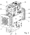
Figur 2 ist das Modul mit Leiterplattenabschnitten (23, 24, 25) gezeigt, auf welchen die Wärme erzeugenden elektronischen Bauelemente, insbesondere Leistungshalbleiter, bestückt sind. - In der
Figur 3 ist eine zugehörige Schnittansicht gezeigt. - In der
Figur 4 ist eine Schrägansicht eines mehrere solche Module aufnehmendes Gehäuses, insbesondere Schaltschrankgehäuses, gezeigt. - In der
Figur 5 ist eine zugehörige Schnittansicht gezeigt. - Wie in den
Figuren 1 bis 3 gezeigt, weist das Modul eine zentrale Belüftung zum Entwärmen der von den Wärmeerzeugenden Bauelementen erzeugten Wärme auf. Hierzu ist ein Kühlkörper 1 vorgesehen, der als einstückig oder mehrstückig ausgeführtes Stranggussteil gefertigt ist. - Dieser Kühlkörper 1 ist hohl ausgeführt und weist in den Hohlraum hineinragende Kühlrippen 30 auf. Somit ist die Hohlraumoberfläche vergrößert und der Wärmeübergangswiderstand vom Kühlkörper 1 zum den Hohlraum durchströmenden Kühlmedium, insbesondere Kühlluft, verringert.
- Da der Kühlkörper 1 ein Stranggussteil ist, insbesondere ein Aluminium-Stranggussteil, ist der Hohlraum durchgehend und die Kühlrippen 30 sowie der Hohlraum verlaufen in Stranggussrichtung.
- Der Kühlkörper ist beispielhaft als Quader ausgeführt und weist somit vier in etwa ebene Seitenflächen auf. Zur Kontaktierung der Wärme erzeugenden Bauelemente weisen zumindest zwei Seitenflächen, insbesondere die zwei sich diametral gegenüberstehenden Seitenflächen, Kontaktflächen 2 auf, die fein bearbeitet sind, insbesondere also gefräst und/oder geschliffen und/oder sandgestrahlt oder dergleichen. Somit sind die Bauelemente an die Kontaktfläche andrückbar, insbesondere mit zwischengeordneter Wärmeleitpaste, und ein guter Wärmeübergang erreichbar.
- An die beiden anderen Seitenflächen ist jeweils ein Ferritteil 31 angedrückt oder sonstig verbunden, so dass die von einer Wicklung 32 erzeugte Wärme über den Ferrit 31 an den Kühlkörper 1 leitbar ist. Dabei ist das Ferritteil 31 als Spulenkern der Wicklung 32 verwendet, so dass also das von der Wicklung 32 erzeugte Magnetfeld vom Ferritteil 31 gebündelt und geleitet wird.
- Die Wicklung ist als Induktivität eines DC-DC Wandlers verwendet, also als Booster-Drossel eines DC-DC -Boosters.
- Der Hohlraum des Kühlkörpers 1 mündet an seiner ersten Öffnung in Stranggussrichtung in ein Luftleitteil 3, welches aus Kunststoff gefertigt ist und auf den Kühlkörper 1 aufgesteckt ist. Außerdem weist das Luftleitteil 3 an seinem von dem Kühlkörper 1 abgewandten Endbereich einen Flansch auf, mit dem es an einer Montageplatte 42 anschraubbar ist. Die Montageplatte 42 weist eine Ausnehmung auf, so dass das Kühlmedium nach Durchströmen des Kühlkörpers 1 und des Luftleitteils 3 die Ausnehmung der Montageplatte 42 durchströmt und in einen in
Figur 5 gezeigten Luftkanal 50 einströmt. - Auf seinem von dem Luftleitteil 3 abgewandten Endbereich mündet der Hohlraum des Kühlkörpers 1 in ein Luftleitteil 4, in welchem ein Lüfter angeordnet ist.
- Die Ferritteile 31 sind vorzugsweise schraubverbunden mit dem Kühlkörper 1 und somit angedrückt an diesen oder von einem mit dem Kühlkörper 1 schraubverbundenen Teil an den Kühlkörper 1 angedrückt.
- Die Wärme erzeugenden Bauelemente sind auf einer der Leiterplatten (23, 25) bestückt. Diese Leiterplatten (23, 25) sind Teil einer flexiblen Leiterplattenanordnung. Hierbei sind die Leiterplatten (23, 24, 25) über zwischengeordnete flexible Bereiche 26 verbunden. Zur Herstellung dieser Leiterplattenanordnung wird von einer großen Leiterplatte das Trägermaterial, insbesondere Epoxidharz, in einem jeweiligen Teilbereich mechanisch herausgelöst, insbesondere herausgefräst, oder chemisch herausgelöst. Somit verbleiben in diesen nun als flexible Bereiche 26 fungierenden Teilbereichen nur noch die metallischen Leiterbahnen und eine jeweilige diese tragende Folie.
- Die Leiterplattenanordnung sind somit um den Kühlkörper 1 herum gewunden, so dass die Wärme erzeugenden Bauelemente an den Kontaktflächen 2 der sich gegenüber angeordneten Außenflächen des Kühlkörpers 1 andrückbar sind.
- Auf der zwischen den Leiterplatten (23, 25) zwischengeordneten Leiterplatte 24 ist die Induktivität eines DC-DC-Boosters angeordnet, deren Spulenkern, insbesondere Ferritteil 31, wärmeleitend verbunden, insbesondere angedrückt ist, an den Kühlkörper 1.
- Auch auf der hierzu gegenüber angeordneten Außen-Seitenfläche ist eine ebensolche Induktivität eines oder des DC-DC-Boosters angeordnet, deren Spulenkern, insbesondere Ferritteil, wärmeleitend verbunden, insbesondere angedrückt ist, an den Kühlkörper 1.
- Somit ist eine leistungsfähige Entwärmung der Wärme erzeugenden Bauelemente der elektronischen Schaltung erreicht. Insbesondere sind hierbei als Wärme erzeugende Bauelemente Leistungshalbleiterschalter und Spulenkerne der Wicklungen 32 beispielhaft erwähnt. Diese Wärme erzeugenden Bauelemente sind also jeweils auf der dem Kühlkörper 1 zugewandten Seite der jeweiligen Leiterplatte (23, 24, 25) angeordnet.
- Mittels des Lüfters ist ein Kühlluftstrom antreibbar, so dass die Entwärmung sehr effektiv ausführbar ist. Aber auch ohne Lüfter ist eine konvektiv angetriebene Strömung vorhanden und bewirkt eine Entwärmung.
- Wie in
Figur 4 und5 gezeigt, sind in einem Schaltschrank 40 mehrere wie in denFiguren 1 bis 3 zuvor beschriebene Module an einer Montageplatte 42 anordenbar, wobei die Montageplatte 42 zur zentralen Belüftung der jeweiligen Module eine jeweilige durchgehende Ausnehmung aufweist. - Somit mündet ein jeweiliger durch die Luftleitteile (3, 4) und den Hohlraum des Kühlkörpers 1 sowie durch die Ausnehmung in der Montageplatte 42 hindurchführender Kühlkanal in dem im Schaltschrank 40 vertikal hinaufführenden Luftkanal 50, welcher in ein Umlenkteil 41 mündet. Der Luftkanal 50 verläuft dabei innerhalb des Schaltschrankes 40. Das an der Oberseite des Schaltschrankes 40 angeordnete Umlenkteil weist eine zum Luftkanal 50 hin gerichtete Öffnung auf, die an einer an der Oberseite des Umlenkteils 41 angeordnete, horizontal verlaufende Grundplatte umgelenkt wird von der vertikalen in die horizontale Richtung.
- Hierbei ist das Umlenkteil 41 vorzugsweise als Stranggussteil ausgeführt, so dass an der Grundplatte des Umlenkteils 41 Kühlrippen ausgeformt sind. Auf diese Weise gibt das vorbei strömende Kühlmedium Wärme ab an das Umlenkteil 41, welches dann zumindest auch an seiner Oberseite Wärme an die Umgebung, insbesondere Umgebungsluft, abführt.
- Somit wird der Kühlluftstrom durch die Kühlkanäle der zentral belüfteten Module und durch die Montageplatte 42 geleitet, insbesondere in horizontaler Richtung bei vertikaler Ausrichtung der Montageplatte 42.
- Die von den Lüftern in den Luftleitteilen 4 der Module angesaugte Luft wird von außen durch ein in der Gehäusewand des Schaltschrankes 40 vorgesehenes Lüftergitter 43 ins Gehäuseinnere geleitet und von dort von den Lüftern angesaugt.
- Die Montageplatte 42 trennt also das Gehäuseinnere von dem Luftkanal 50 und somit die kühlere Luft von der wärmeren Abluft der Module.
- Das jeweilige Modul ist mittels seines Luftleitteils 3 gehalten an der Montageplatte 42. Hierbei sind vorzugsweise an der der Montageplatte 42 zugewandten Seite Gewindebohrungen in dem Luftleitteil 3 eingebracht, so dass das Luftleitteil 3 mittels Schrauben an die Montageplatte anschraubbar ist. Bevorzugt gehen hierbei die Schrauben durch die Montageplatte 42.
- Statt Luft ist auch ein anderes Kühlmedium verwendbar.
- Mittels der zur Oberseite hin abdeckend wirksamen Grundplatte des Umlenkteils 41 ist ein Hereinfallen von Schmutzpartikeln in den Luftkanal 50 verhinderbar.
- In der
Figur 5 ist die Strömung des Kühlmediums durch Pfeile verdeutlicht. - In der
Figur 4 sind die elektrischen Versorgungsleitungen, Datenbusleitungen und Ausgangsleitungen der Module mit jeweiligen schwarzen Linien angedeutet. - Somit ist in den
Figuren 4 und5 nun ein Schaltschrankgehäuse, in welchem eine Vielzahl von zentral belüfteten Modulen anordenbar und entwärmbar sind. - Die jeweiligen Module sind entweder alle gleichartig ausgeführt oder unterschiedlich zu zumindest einem der Module.
- Die konkrete Ausführung nach
Figur 1 bis 3 ist beispielhaft. Bei erfindungsgemäßen Ausführungsbeispielen ist wichtig, dass zentral im Modul ein hohler Kühlkörper, insbesondere Stranggussteil, angeordnet ist, an dessen Außenseite Wärme erzeugende Bauelemente wärmeleitend verbunden sind. Dabei sind diese Bauelemente auf derselben Leiterplatte bestückt oder jeweils auf separaten, also voneinander beabstandeten, miteinander nicht verbundenen Leiterplatten. Wenn die Leiterplatten miteinander verbunden sind, sind sie beispielhaft in der nachFigur 1 bis 3 gezeigten Weise verbunden, also über zwischengeordnete flexible Bereiche. Die Ausführung der flexiblen Bereiche als Teilbereiche einer ursprünglichen großen Leiterplatte, welche alle Leiterplatten des Moduls sowie die flexiblen Bereiche umfasst, ist nicht zwingend. Alternativ oder zusätzlich dürfen die flexiblen Bereiche nämlich auch als Gelenkteile ausgeführt werden, insbesondere also als Scharniere oder drehbare Verbindungselemente. - Bei einem weiteren erfindungsgemäßen Ausführungsbeispiel ist statt eines quaderförmigen, vier, in etwa ebene Außen-Seitenflächen aufweisenden Kühlkörpers ein polygonaler Kühlkörper verwendet, der drei, fünf, sechs oder mehr, in etwa ebene Außen-Seitenflächen aufweist.
- Bei einem weiteren erfindungsgemäßen Ausführungsbeispiel ist statt des Schaltschrankgehäuses ein anderes Gehäuse verwendet, wobei statt des Lüftergitters 43 entweder eine Ausnehmung im Gehäuse anordenbar ist. Außerdem ist statt des Umlenkteils 41 auch ein anderes Luftleitteil verwendbar, beispielsweise ein Absaugrohr, welches mit dem Luftkanal 50 verbunden ist, oder ein Luftleitteil, das den Kühlluftstrom des Luftkanals 50 in eine andere Richtung lenkt.
-
- 1 Kühlkörper
- 2 Kontaktfläche
- 3 Luftleitteil
- 4 Luftleitteil
- 5 Schraube
- 20 Halteplatte, insbesondere metallisch
- 21 Isolierteil
- 22 Schraube
- 23 Leiterplatte
- 24 Leiterplatte
- 25 Leiterplatte
- 26 flexibler Bereich
- 30 Kühlrippen
- 31 Ferritteil
- 32 Wicklung
- 40 Schaltschrank
- 41 Umlenkteil
- 42 Montageplatte
- 43 Lüftergitter
- 50 Luftkanal
Claims (8)
- Schaltschrank (40) mit Gehäuse,wobei das Gehäuse mehrere Module gehäusebildend umgibt,wobei jedes Modul zentral belüftet ist und einen von einem Kühlmedium durchströmten Kühlkörper (1) mit einem durchgehenden Hohlraum aufweist, welcher als Kühlkanal fungiert,wobei die als Kühlkanal ausgeführte zentrale Belüftung jedes Moduls in einen innerhalb des Gehäuses angeordneten Sammelkanal mündet,wobei der Sammelkanal zu einem als Umlenkteil (41) ausgeführten Luftleitteil des Gehäuses führt, wobei das Luftleitteil eine zur Umgebung hin gerichtete Öffnung aufweist,wobei eine Speisung der zentralen Belüftung aus einem von dem Gehäuse umgebenen Innenbereich des Schatschranks (40) erfolgt,wobei das Gehäuse eine Ausnehmung aufweist, durch welche der Innenbereich mit einem Kühlmediumstrom speisbar ist,wobei innerhalb des Gehäuses zwischen Innenbereich und Sammelkanal eine Montageplatte (42) angeordnet ist,wobei der Innenbereich mittels der Montageplatte (42) vom Sammelkanal abgegrenzt ist wobei jedes Modul ein erstes Luftleitteil (4) und ein von dem ersten Luftleitteil mittels des Kühlkörpers beabstandetes weiteres Luftleitteil (3) aufweist,wobei das erste Luftleitteil (4) einen Lüfter umfasst und das weitere Luftleitteil (3) zum Halten des Kühlkörpers (1) an der Montageplatte (42) dient, wobei das weitere Luftleitteil (3) zwischen dem Kühlkörper (1) und der Montageplatte (42) angeordnet ist,wobei die Module mit der Montageplatte (42) jeweils verbunden sind und das jeweilige Modul mittels seines Luftleitteils (3) an der Montageplatte (42) gehalten ist insbesondere wobei an der der Montageplatte (42) zugewandten Seite Gewindebohrungen in dem Luftleitteil (3) eingebracht sind, so dass das Luftleitteil (3) mittels Schrauben an die Montageplatte angeschraubt ist,wobei die Montageplatte (42) eine dem jeweiligen Modul, zugeordnete, durch die Montageplatte (42) durchgehende Ausnehmung aufweist, zur Durchströmung mittels des Kühlmediumstroms.wobei ein wärme erzeugendes Bauelement auf einer Leiterplatte (23, 24, 25) bestückt ist wobei seine elektrischen Anschlusselemente lötverbunden sind mit einem Leiterbahnabschnitt,wobei die Leiterplatte (23, 24, 25) mittels einer Haltevorrichtung mit dem Kühlkörper (1) verbunden ist,die Leiterplatte (23, 24, 25) eine Anordnung aus mittels flexibler Bereiche (26) verbundenen Leiterplatten (23, 24, 25) ist,wobei die Anordnung den Kühlkörper (1) in Umfangsrichtung des Kühlkanals zumindest teilweise umgibt.
- Schaltschrank (40) nach Anspruch 1, dadurch gekennzeichnet, dass jedes Luftleitteil (3, 4) als Stranggussteil gefertigt ist.
- Schaltschrank (40) nach einem der vorangegangenen Ansprüche, dadurch gekennzeichnet, dassder aus dem Sammelkanal ausströmende Kühlmediumstrom an Kühlrippen (30) entlang in die Umgebung herausgeleitet wird,hierbei der Kühlmediumstrom umgelenkt wird, von einer im Wesentlichen vertikalen in eine im Wesentlichen horizontale Richtung.
- Schaltschrank (40) nach einem der vorangegangenen Ansprüche, dadurch gekennzeichnet, dass jedes Luftleitteil (3, 4) eine Grundplatte aufweist, an welcher dem Innenraum der Vorrichtung zugewandte Kühlrippen angeordnet sind,
- Schaltschrank (40) nach einem der vorangegangenen Ansprüche, dadurch gekennzeichnet, dass der Innenbereich durch zumindest die Montageplatte (42), das Gehäuse und das Lüftergitter (43) begrenzt ist und dass der Sammelkanal durch zumindest die Montageplatte (42) und das Gehäuse begrenzt ist.
- Schaltschrank (40) nach einem der vorangegangenen Ansprüche, dadurch gekennzeichnet, dass der Kühlkörper (1) als Stranggussteil ausgeführt ist
- Schaltschrank (40) nach einem der vorangegangenen Ansprüche, dadurch gekennzeichnet, dass
ein oder mehrere Wärme erzeugende Bauelemente an einem jeweiligen Außenflächenabschnitt wärmeleitend verbunden sind. - Schaltschrank (40) nach einem der vorangegangenen Ansprüche,
dadurch gekennzeichnet, dassdie Haltevorrichtung ein auf die Leiterplatte (23, 24, 25) Isoliermittel ist, welches von einer metallischen Halteplatte (20), auf die Leiterplatte (23, 24, 25) gedrückt ist,wobei die Halteplatte (20) an den Kühlkörper (1) angeschraubt oder von einem mit dem Kühlkörper (1) schraubverbundenen Federelement an das Isoliermittel angedrückt ist.
Applications Claiming Priority (2)
| Application Number | Priority Date | Filing Date | Title |
|---|---|---|---|
| DE102012001119.9A DE102012001119B4 (de) | 2012-01-23 | 2012-01-23 | Schaltschrank mit Gehäuse mit darin angeordneten zentral belüfteten Modulen zur Entwärmung |
| PCT/EP2013/000038 WO2013110431A1 (de) | 2012-01-23 | 2013-01-09 | Vorrichtung, insbesondere schaltschrank, mit gehäuse |
Publications (3)
| Publication Number | Publication Date |
|---|---|
| EP2807909A1 EP2807909A1 (de) | 2014-12-03 |
| EP2807909C0 EP2807909C0 (de) | 2024-11-13 |
| EP2807909B1 true EP2807909B1 (de) | 2024-11-13 |
Family
ID=47714001
Family Applications (1)
| Application Number | Title | Priority Date | Filing Date |
|---|---|---|---|
| EP13703989.7A Active EP2807909B1 (de) | 2012-01-23 | 2013-01-09 | Schaltschrank mit gehäuse |
Country Status (3)
| Country | Link |
|---|---|
| EP (1) | EP2807909B1 (de) |
| DE (1) | DE102012001119B4 (de) |
| WO (1) | WO2013110431A1 (de) |
Cited By (1)
| Publication number | Priority date | Publication date | Assignee | Title |
|---|---|---|---|---|
| CN120222198A (zh) * | 2025-04-01 | 2025-06-27 | 南京永恒电器有限公司 | 一种紧凑防护型开关柜 |
Families Citing this family (10)
| Publication number | Priority date | Publication date | Assignee | Title |
|---|---|---|---|---|
| DE102014104857A1 (de) * | 2014-04-04 | 2015-10-08 | Armin Meininger | Vorrichtung zur Klimatisierung elektronischer Baugruppen |
| WO2016008509A1 (en) * | 2014-07-15 | 2016-01-21 | Abb Technology Ltd | Electric module for improved thermal management in electrical equipments |
| DE102017002601A1 (de) | 2017-03-17 | 2018-09-20 | Man Truck & Bus Ag | Kühlvorrichtung für elektronisches Steuergerät |
| DE102017206774B4 (de) * | 2017-04-21 | 2025-08-14 | Lenze Se | Elektrisches Steuergerät |
| DE102017109997B3 (de) | 2017-05-09 | 2018-04-26 | Rittal Gmbh & Co. Kg | Entwärmungsanordnung für einen Schaltschrank |
| EP3651336A1 (de) * | 2018-11-08 | 2020-05-13 | Siemens Aktiengesellschaft | Gleichstromschalter |
| DE102018221420B4 (de) * | 2018-12-11 | 2022-03-31 | Zf Friedrichshafen Ag | Steuergerät zur Auswertung von Signalen für ein Fahrzeug |
| DE102020106404A1 (de) | 2020-03-10 | 2021-09-16 | Schaeffler Technologies AG & Co. KG | Kühlbare elektronische Baueinheit und elektromotorische Antriebseinrichtung |
| CN113363860A (zh) * | 2021-06-10 | 2021-09-07 | 沈阳华德海泰电器有限公司 | 12kV/4000A大电流气体绝缘金属封闭开关设备 |
| CN118867863A (zh) * | 2024-08-05 | 2024-10-29 | 河北正飞电气设备科技有限公司 | 一种智能的装配式配电箱 |
Citations (6)
| Publication number | Priority date | Publication date | Assignee | Title |
|---|---|---|---|---|
| DE8509176U1 (de) * | 1985-03-27 | 1985-05-30 | Itronic Fuchs GmbH, 7809 Denzlingen | Luftwärmetauscher zum Kühlen von Bauelementen der Leistungselektronik |
| JP2005142379A (ja) * | 2003-11-07 | 2005-06-02 | Toyota Industries Corp | 電子機器装置 |
| DE102004030675A1 (de) * | 2004-06-24 | 2005-11-10 | Nft Nanofiltertechnik Gmbh | Kühleinrichtung für elektronische Bauelemente |
| US7148452B2 (en) * | 2001-04-03 | 2006-12-12 | Emerson Electric Co. | Heat sink for printed circuit board components |
| DE102007038676A1 (de) * | 2007-08-15 | 2009-02-26 | Sew-Eurodrive Gmbh & Co. Kg | Elektrogerät und Antrieb |
| DE102010045022A1 (de) * | 2009-11-05 | 2011-07-14 | Knürr AG, 94424 | Anordnung zum Kühlen von elektrischen und elektronischen Bauteilen und Moduleinheiten in Geräteschränken |
Family Cites Families (7)
| Publication number | Priority date | Publication date | Assignee | Title |
|---|---|---|---|---|
| US3149666A (en) * | 1961-06-15 | 1964-09-22 | Wakefield Eng Inc | Cooler |
| FR2193303B1 (de) * | 1972-07-24 | 1976-01-16 | Merlin Gerin | |
| DE3710198A1 (de) * | 1987-03-27 | 1988-10-06 | Zentro Elektrik Gmbh Kg | Kuehlbare anordnung |
| US6504714B1 (en) | 2000-08-16 | 2003-01-07 | Square D Company | Multi-level thermal management system and method |
| US7423871B2 (en) * | 2003-11-14 | 2008-09-09 | Det International Holding Limited | Electric device with improved cooling and casing therefor |
| JP2005328659A (ja) * | 2004-05-14 | 2005-11-24 | Sansha Electric Mfg Co Ltd | 電子負荷装置および電源装置の防塵冷却構造 |
| DE102008060613B4 (de) * | 2008-12-09 | 2022-09-15 | Sew-Eurodrive Gmbh & Co Kg | Kühlanordnung für einen in einem Schaltschrank angeordneten Umrichter |
-
2012
- 2012-01-23 DE DE102012001119.9A patent/DE102012001119B4/de active Active
-
2013
- 2013-01-09 WO PCT/EP2013/000038 patent/WO2013110431A1/de not_active Ceased
- 2013-01-09 EP EP13703989.7A patent/EP2807909B1/de active Active
Patent Citations (6)
| Publication number | Priority date | Publication date | Assignee | Title |
|---|---|---|---|---|
| DE8509176U1 (de) * | 1985-03-27 | 1985-05-30 | Itronic Fuchs GmbH, 7809 Denzlingen | Luftwärmetauscher zum Kühlen von Bauelementen der Leistungselektronik |
| US7148452B2 (en) * | 2001-04-03 | 2006-12-12 | Emerson Electric Co. | Heat sink for printed circuit board components |
| JP2005142379A (ja) * | 2003-11-07 | 2005-06-02 | Toyota Industries Corp | 電子機器装置 |
| DE102004030675A1 (de) * | 2004-06-24 | 2005-11-10 | Nft Nanofiltertechnik Gmbh | Kühleinrichtung für elektronische Bauelemente |
| DE102007038676A1 (de) * | 2007-08-15 | 2009-02-26 | Sew-Eurodrive Gmbh & Co. Kg | Elektrogerät und Antrieb |
| DE102010045022A1 (de) * | 2009-11-05 | 2011-07-14 | Knürr AG, 94424 | Anordnung zum Kühlen von elektrischen und elektronischen Bauteilen und Moduleinheiten in Geräteschränken |
Cited By (1)
| Publication number | Priority date | Publication date | Assignee | Title |
|---|---|---|---|---|
| CN120222198A (zh) * | 2025-04-01 | 2025-06-27 | 南京永恒电器有限公司 | 一种紧凑防护型开关柜 |
Also Published As
| Publication number | Publication date |
|---|---|
| EP2807909C0 (de) | 2024-11-13 |
| DE102012001119A1 (de) | 2013-07-25 |
| EP2807909A1 (de) | 2014-12-03 |
| DE102012001119B4 (de) | 2022-11-17 |
| WO2013110431A1 (de) | 2013-08-01 |
Similar Documents
| Publication | Publication Date | Title |
|---|---|---|
| EP2807909B1 (de) | Schaltschrank mit gehäuse | |
| EP2807908B1 (de) | Vorrichtung, insbesondere schaltschrank, mit gehäuse | |
| EP3763177B1 (de) | Elektrogeräteanordnung, aufweisend ein an einem tragelement, insbesondere einer wand, befestigbares elektrogerät | |
| EP1610452B1 (de) | Wechselrichter mit einem Gehäuse mit Kühlkörper aufweisenden elektrischen und/oder elektronischen Komponenten | |
| EP1848260B1 (de) | Wechselrichter | |
| WO1996034519A1 (de) | Gehäuseaufbau für im freien aufstellbare, elektrische und/oder elektronische geräte | |
| DE112015005727T5 (de) | Schaltungsanordnung und elektrischer Verteiler | |
| EP2291064B1 (de) | Elektronische Einheit mit Kühlrippen | |
| EP2577850A2 (de) | Elektrische antriebsanordnung | |
| DE102012011638A1 (de) | Elektronische Steuerungsvorrichtung | |
| EP2299582A1 (de) | Wechselrichter mit einem Gehäuse und darin angeordneten elektrischen und elektronischen Bauteilen | |
| WO2013107625A1 (de) | Anordnung, insbesondere energiespeicherzellenanordnung | |
| DE102008033193A1 (de) | Motorsteuerungsvorrichtung eines Fahrzeugs | |
| DE112016005686T5 (de) | Elektrischer Verteiler | |
| DE102006003563B4 (de) | Lüfter für einen Halbleiter oder dergleichen | |
| EP2317618B1 (de) | Elektrisches Installationseinbaugerät mit zumindest einer Wärme erzeugenden elektrischen Komponente | |
| EP4010966A1 (de) | Antrieb mit segmentiertem umrichtergehäuse | |
| DE102018202892A1 (de) | Basiseinheit, Motor und Luftblasvorrichtung | |
| DE102012013741A1 (de) | Anordnung zum Kühlen, Elektrogerät und Verwendung einer Anordnung zum Kühlen | |
| DE102012014011A1 (de) | Elektrogerät | |
| DE102011006779B4 (de) | Anordnung zum Kühlen von elektronischen Komponenten | |
| EP3930434A1 (de) | Baugruppe mit einem eine tragstruktur ausbildenden kühlkörperkernelement | |
| EP4049517B1 (de) | Anordnung mit elektrogerät, insbesondere umrichter oder wechselrichter, und komponente | |
| EP3629688A1 (de) | Stromrichter mit einem separaten innenraum | |
| DE102012008550B4 (de) | Stromschienenteil |
Legal Events
| Date | Code | Title | Description |
|---|---|---|---|
| PUAI | Public reference made under article 153(3) epc to a published international application that has entered the european phase |
Free format text: ORIGINAL CODE: 0009012 |
|
| 17P | Request for examination filed |
Effective date: 20140825 |
|
| AK | Designated contracting states |
Kind code of ref document: A1 Designated state(s): AL AT BE BG CH CY CZ DE DK EE ES FI FR GB GR HR HU IE IS IT LI LT LU LV MC MK MT NL NO PL PT RO RS SE SI SK SM TR |
|
| DAX | Request for extension of the european patent (deleted) | ||
| STAA | Information on the status of an ep patent application or granted ep patent |
Free format text: STATUS: EXAMINATION IS IN PROGRESS |
|
| 17Q | First examination report despatched |
Effective date: 20180124 |
|
| GRAP | Despatch of communication of intention to grant a patent |
Free format text: ORIGINAL CODE: EPIDOSNIGR1 |
|
| STAA | Information on the status of an ep patent application or granted ep patent |
Free format text: STATUS: GRANT OF PATENT IS INTENDED |
|
| INTG | Intention to grant announced |
Effective date: 20240703 |
|
| GRAS | Grant fee paid |
Free format text: ORIGINAL CODE: EPIDOSNIGR3 |
|
| GRAA | (expected) grant |
Free format text: ORIGINAL CODE: 0009210 |
|
| STAA | Information on the status of an ep patent application or granted ep patent |
Free format text: STATUS: THE PATENT HAS BEEN GRANTED |
|
| AK | Designated contracting states |
Kind code of ref document: B1 Designated state(s): AL AT BE BG CH CY CZ DE DK EE ES FI FR GB GR HR HU IE IS IT LI LT LU LV MC MK MT NL NO PL PT RO RS SE SI SK SM TR |
|
| REG | Reference to a national code |
Ref country code: GB Ref legal event code: FG4D Free format text: NOT ENGLISH |
|
| REG | Reference to a national code |
Ref country code: CH Ref legal event code: EP |
|
| REG | Reference to a national code |
Ref country code: DE Ref legal event code: R096 Ref document number: 502013016552 Country of ref document: DE |
|
| REG | Reference to a national code |
Ref country code: IE Ref legal event code: FG4D Free format text: LANGUAGE OF EP DOCUMENT: GERMAN |
|
| U01 | Request for unitary effect filed |
Effective date: 20241127 |
|
| U07 | Unitary effect registered |
Designated state(s): AT BE BG DE DK EE FI FR IT LT LU LV MT NL PT RO SE SI Effective date: 20241203 |
|
| U20 | Renewal fee for the european patent with unitary effect paid |
Year of fee payment: 13 Effective date: 20250303 |
|
| PG25 | Lapsed in a contracting state [announced via postgrant information from national office to epo] |
Ref country code: HR Free format text: LAPSE BECAUSE OF FAILURE TO SUBMIT A TRANSLATION OF THE DESCRIPTION OR TO PAY THE FEE WITHIN THE PRESCRIBED TIME-LIMIT Effective date: 20241113 Ref country code: IS Free format text: LAPSE BECAUSE OF FAILURE TO SUBMIT A TRANSLATION OF THE DESCRIPTION OR TO PAY THE FEE WITHIN THE PRESCRIBED TIME-LIMIT Effective date: 20250313 |
|
| PG25 | Lapsed in a contracting state [announced via postgrant information from national office to epo] |
Ref country code: ES Free format text: LAPSE BECAUSE OF FAILURE TO SUBMIT A TRANSLATION OF THE DESCRIPTION OR TO PAY THE FEE WITHIN THE PRESCRIBED TIME-LIMIT Effective date: 20241113 |
|
| PG25 | Lapsed in a contracting state [announced via postgrant information from national office to epo] |
Ref country code: NO Free format text: LAPSE BECAUSE OF FAILURE TO SUBMIT A TRANSLATION OF THE DESCRIPTION OR TO PAY THE FEE WITHIN THE PRESCRIBED TIME-LIMIT Effective date: 20250213 |
|
| PG25 | Lapsed in a contracting state [announced via postgrant information from national office to epo] |
Ref country code: GR Free format text: LAPSE BECAUSE OF FAILURE TO SUBMIT A TRANSLATION OF THE DESCRIPTION OR TO PAY THE FEE WITHIN THE PRESCRIBED TIME-LIMIT Effective date: 20250214 |
|
| PG25 | Lapsed in a contracting state [announced via postgrant information from national office to epo] |
Ref country code: PL Free format text: LAPSE BECAUSE OF FAILURE TO SUBMIT A TRANSLATION OF THE DESCRIPTION OR TO PAY THE FEE WITHIN THE PRESCRIBED TIME-LIMIT Effective date: 20241113 |
|
| PG25 | Lapsed in a contracting state [announced via postgrant information from national office to epo] |
Ref country code: RS Free format text: LAPSE BECAUSE OF FAILURE TO SUBMIT A TRANSLATION OF THE DESCRIPTION OR TO PAY THE FEE WITHIN THE PRESCRIBED TIME-LIMIT Effective date: 20250213 |
|
| PG25 | Lapsed in a contracting state [announced via postgrant information from national office to epo] |
Ref country code: SM Free format text: LAPSE BECAUSE OF FAILURE TO SUBMIT A TRANSLATION OF THE DESCRIPTION OR TO PAY THE FEE WITHIN THE PRESCRIBED TIME-LIMIT Effective date: 20241113 |
|
| PG25 | Lapsed in a contracting state [announced via postgrant information from national office to epo] |
Ref country code: SK Free format text: LAPSE BECAUSE OF FAILURE TO SUBMIT A TRANSLATION OF THE DESCRIPTION OR TO PAY THE FEE WITHIN THE PRESCRIBED TIME-LIMIT Effective date: 20241113 |
|
| PG25 | Lapsed in a contracting state [announced via postgrant information from national office to epo] |
Ref country code: CZ Free format text: LAPSE BECAUSE OF FAILURE TO SUBMIT A TRANSLATION OF THE DESCRIPTION OR TO PAY THE FEE WITHIN THE PRESCRIBED TIME-LIMIT Effective date: 20241113 |
|
| REG | Reference to a national code |
Ref country code: CH Ref legal event code: PL |
|
| PG25 | Lapsed in a contracting state [announced via postgrant information from national office to epo] |
Ref country code: MC Free format text: LAPSE BECAUSE OF FAILURE TO SUBMIT A TRANSLATION OF THE DESCRIPTION OR TO PAY THE FEE WITHIN THE PRESCRIBED TIME-LIMIT Effective date: 20241113 |
|
| PLBE | No opposition filed within time limit |
Free format text: ORIGINAL CODE: 0009261 |
|
| STAA | Information on the status of an ep patent application or granted ep patent |
Free format text: STATUS: NO OPPOSITION FILED WITHIN TIME LIMIT |
|
| PG25 | Lapsed in a contracting state [announced via postgrant information from national office to epo] |
Ref country code: CH Free format text: LAPSE BECAUSE OF NON-PAYMENT OF DUE FEES Effective date: 20250131 |
|
| 26N | No opposition filed |
Effective date: 20250814 |
|
| PGFP | Annual fee paid to national office [announced via postgrant information from national office to epo] |
Ref country code: GB Payment date: 20251204 Year of fee payment: 14 |
|
| PG25 | Lapsed in a contracting state [announced via postgrant information from national office to epo] |
Ref country code: IE Free format text: LAPSE BECAUSE OF NON-PAYMENT OF DUE FEES Effective date: 20250109 |
|
| U20 | Renewal fee for the european patent with unitary effect paid |
Year of fee payment: 14 Effective date: 20260202 |