EP2807909B1 - Armoire de commande avec boîtier - Google Patents
Armoire de commande avec boîtier Download PDFInfo
- Publication number
- EP2807909B1 EP2807909B1 EP13703989.7A EP13703989A EP2807909B1 EP 2807909 B1 EP2807909 B1 EP 2807909B1 EP 13703989 A EP13703989 A EP 13703989A EP 2807909 B1 EP2807909 B1 EP 2807909B1
- Authority
- EP
- European Patent Office
- Prior art keywords
- mounting plate
- air
- heat sink
- housing
- cooling
- Prior art date
- Legal status (The legal status is an assumption and is not a legal conclusion. Google has not performed a legal analysis and makes no representation as to the accuracy of the status listed.)
- Active
Links
Images



Classifications
-
- H—ELECTRICITY
- H05—ELECTRIC TECHNIQUES NOT OTHERWISE PROVIDED FOR
- H05K—PRINTED CIRCUITS; CASINGS OR CONSTRUCTIONAL DETAILS OF ELECTRIC APPARATUS; MANUFACTURE OF ASSEMBLAGES OF ELECTRICAL COMPONENTS
- H05K7/00—Constructional details common to different types of electric apparatus
- H05K7/20—Modifications to facilitate cooling, ventilating, or heating
- H05K7/2089—Modifications to facilitate cooling, ventilating, or heating for power electronics, e.g. for inverters for controlling motor
- H05K7/20909—Forced ventilation, e.g. on heat dissipaters coupled to components
- H05K7/20918—Forced ventilation, e.g. on heat dissipaters coupled to components the components being isolated from air flow, e.g. hollow heat sinks, wind tunnels or funnels
-
- H—ELECTRICITY
- H05—ELECTRIC TECHNIQUES NOT OTHERWISE PROVIDED FOR
- H05K—PRINTED CIRCUITS; CASINGS OR CONSTRUCTIONAL DETAILS OF ELECTRIC APPARATUS; MANUFACTURE OF ASSEMBLAGES OF ELECTRICAL COMPONENTS
- H05K7/00—Constructional details common to different types of electric apparatus
- H05K7/20—Modifications to facilitate cooling, ventilating, or heating
- H05K7/20536—Modifications to facilitate cooling, ventilating, or heating for racks or cabinets of standardised dimensions, e.g. electronic racks for aircraft or telecommunication equipment
- H05K7/20554—Forced ventilation of a gaseous coolant
- H05K7/20572—Forced ventilation of a gaseous coolant within cabinets for removing heat from sub-racks, e.g. plenum
-
- H—ELECTRICITY
- H05—ELECTRIC TECHNIQUES NOT OTHERWISE PROVIDED FOR
- H05K—PRINTED CIRCUITS; CASINGS OR CONSTRUCTIONAL DETAILS OF ELECTRIC APPARATUS; MANUFACTURE OF ASSEMBLAGES OF ELECTRICAL COMPONENTS
- H05K7/00—Constructional details common to different types of electric apparatus
- H05K7/20—Modifications to facilitate cooling, ventilating, or heating
- H05K7/20709—Modifications to facilitate cooling, ventilating, or heating for server racks or cabinets; for data centers, e.g. 19-inch computer racks
- H05K7/20718—Forced ventilation of a gaseous coolant
- H05K7/20736—Forced ventilation of a gaseous coolant within cabinets for removing heat from server blades
Definitions
- the invention relates to a control cabinet with housing.
- the invention is therefore based on the object of providing improved heat dissipation.
- the object is achieved in the device according to the features specified in claim 1.
- the advantage here is that a large heat dissipation surface can be achieved through the large number of modules and a large amount of heat dissipation can also be achieved through the central ventilation.
- the central ventilation is supplied from an interior area of the device surrounded by the housing.
- the advantage here is that a pressure-equalizing interior area is used to supply several central ventilation systems, which may have different suction strengths.
- fans can be used in the modules, the performance of which depends on the required or predicted performance varies.
- the cooling air flow depends on the performance of the fan.
- the large interior area of the device makes it possible to create a pressure buffer.
- the housing has a recess through which the interior can be supplied with a cooling medium flow, in particular, a fan grille is arranged in the recess of the housing.
- a fan grille is arranged in the recess of the housing.
- the advantage here is that only a single recess needs to be protected by a fan grille.
- the fan grille can also be designed with such a fine mesh that the cooling air flow can be filtered, i.e. correspondingly large dirt particles can be filtered out of the cooling air flow.
- a mounting plate is arranged within the housing between the interior and the collecting duct, in particular, the interior area is separated from the collecting duct by means of a mounting plate.
- the modules are connected to the mounting plate, in particular are held by the mounting plate, in particular are screwed together.
- the advantage here is that the mounting plate separating the cooler from the warmer areas also functions as a mechanical holding device.
- the air guide part is manufactured as a continuous cast part.
- the advantage here is that it enables cost-effective production, particularly from aluminum, which has a low thermal resistance.
- the mounting plate has a recess that runs through the mounting plate and is associated with the respective module, in particular its central ventilation and/or its cooling channel, in particular for the flow of the cooling medium.
- the interior area is limited by at least the mounting plate, the housing and the fan grille and/or the collecting duct is limited by at least the mounting plate and the housing.
- the advantage here is that the interior area with cooler air can be easily separated from the collecting duct with warmer air.
- the module has a heat sink with a continuous cavity, which functions as a cooling channel, in particular, the heat sink is designed as a continuous cast part.
- the heat sink can be made in one piece or in multiple pieces and can therefore be made in one piece or in two pieces depending on the respective requirements.
- a large outer surface can be achieved around the cooling channel, so that effective heat dissipation can be achieved.
- one or more heat-generating components are connected to a respective outer surface section in a heat-conducting manner.
- the advantage here is that a large outer surface can be cooled by the central ventilation.
- the outer surface can be assembled from several flat surface sections so that flat circuit boards can be assigned to these sections and the heat-generating components arranged thereon can be brought into heat-conducting contact with the respective outer surface section.
- a heat-generating component is mounted on a printed circuit board, in particular with its electrical connection elements being soldered to a conductor track section,
- the circuit board is connected to the heat sink by means of a holding device.
- the holding device can be arranged on the side of the circuit board facing away from the heat sink and only screws, for example, lead through the circuit board to the heat sink so that the circuit board including components can be pressed towards the heat sink.
- the holding device is an insulating means on the circuit board, which is pressed onto the circuit board by a holding plate, in particular by a metallic holding plate, in particular, the retaining plate is screwed to the heat sink or pressed onto the insulating means by a spring element screwed to the heat sink.
- the printed circuit board is an arrangement of printed circuit boards connected by means of flexible areas, in particular, the arrangement at least partially surrounds the heat sink in the circumferential direction of the cooling channel.
- At least one air guide part is arranged on the heat sink, in particular, wherein a first air guide part comprises a fan and an air guide part spaced from the first air guide part by means of the heat sink serves to hold the heat sink on the mounting plate, in particular wherein the further air guide part is arranged between the heat sink and the mounting plate.
- a first air guide part comprises a fan and an air guide part spaced from the first air guide part by means of the heat sink serves to hold the heat sink on the mounting plate, in particular wherein the further air guide part is arranged between the heat sink and the mounting plate.
- the module has a central ventilation system for dissipating the heat generated by the heat-generating components.
- a heat sink 1 is provided, which is manufactured as a single-piece or multi-piece continuous casting part.
- This heat sink 1 is hollow and has cooling fins 30 protruding into the cavity.
- the cavity surface is enlarged and the heat transfer resistance from the heat sink 1 to the cooling medium flowing through the cavity, in particular cooling air, is reduced.
- the heat sink 1 is a continuously cast part, in particular an aluminum continuously cast part, the cavity is continuous and the cooling fins 30 and the cavity run in the continuous casting direction.
- the heat sink is designed as a cuboid and thus has four approximately flat side surfaces.
- at least two side surfaces in particular the two diametrically opposed Side surfaces, contact surfaces 2, which are finely machined, in particular milled and/or ground and/or sandblasted or the like.
- the components can thus be pressed onto the contact surface, in particular with thermal paste arranged between them, and good heat transfer can be achieved.
- a ferrite part 31 is pressed or otherwise connected to the other two side surfaces, so that the heat generated by a winding 32 can be conducted to the heat sink 1 via the ferrite 31.
- the ferrite part 31 is used as the coil core of the winding 32, so that the magnetic field generated by the winding 32 is bundled and conducted by the ferrite part 31.
- the winding is used as an inductance of a DC-DC converter, i.e. as a booster choke of a DC-DC booster.
- the cavity of the heat sink 1 opens at its first opening in the direction of continuous casting into an air guide part 3, which is made of plastic and is attached to the heat sink 1.
- the air guide part 3 has a flange at its end area facing away from the heat sink 1, with which it can be screwed onto a mounting plate 42.
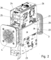
- the mounting plate 42 has a recess so that the cooling medium, after flowing through the heat sink 1 and the air guide part 3, flows through the recess of the mounting plate 42 and into a Figure 5 shown air duct 50.
- the cavity of the heat sink 1 opens into an air guide part 4 in which a fan is arranged.
- the ferrite parts 31 are preferably screw-connected to the heat sink 1 and thus pressed against it or pressed against the heat sink 1 by a part screw-connected to the heat sink 1.
- the heat-generating components are mounted on one of the circuit boards (23, 25). These circuit boards (23, 25) are part of a flexible circuit board arrangement.
- the circuit boards (23, 24, 25) are connected via intermediate flexible areas 26.
- the carrier material in particular epoxy resin, is mechanically removed from a large circuit board in a respective partial area. removed, in particular milled out, or chemically removed.
- these sub-areas which now function as flexible areas 26, only the metallic conductor tracks and a respective film supporting them remain.
- the circuit board arrangement is thus wound around the heat sink 1 so that the heat-generating components can be pressed onto the contact surfaces 2 of the oppositely arranged outer surfaces of the heat sink 1.
- the inductance of a DC-DC booster is arranged on the circuit board 24 arranged between the circuit boards (23, 25), the coil core of which, in particular ferrite part 31, is connected in a heat-conducting manner, in particular pressed, to the heat sink 1.
- heat-generating components of the electronic circuit.
- power semiconductor switches and coil cores of the windings 32 are mentioned as examples of heat-generating components.
- These heat-generating components are therefore each arranged on the side of the respective circuit board (23, 24, 25) facing the heat sink 1.
- the fan can be used to drive a flow of cooling air, so that heat dissipation can be carried out very effectively. But even without a fan, a convectively driven flow is present and causes heat dissipation.
- a control cabinet 40 several as shown in the Figures 1 to 3
- the previously described modules can be arranged on a mounting plate 42, wherein the mounting plate 42 has a respective continuous recess for central ventilation of the respective modules.
- a respective cooling channel leading through the air guide parts (3, 4) and the cavity of the heat sink 1 as well as through the recess in the mounting plate 42 opens into the in the control cabinet 40 vertically upwardly leading air duct 50, which opens into a deflection part 41.
- the air duct 50 runs inside the control cabinet 40.
- the deflection part arranged on the top of the control cabinet 40 has an opening directed towards the air duct 50, which is deflected from the vertical to the horizontal direction on a horizontally running base plate arranged on the top of the deflection part 41.
- the deflection part 41 is preferably designed as a continuous cast part, so that cooling fins are formed on the base plate of the deflection part 41. In this way, the cooling medium flowing past gives off heat to the deflection part 41, which then dissipates heat to the environment, in particular ambient air, at least on its upper side.
- the cooling air flow is guided through the cooling channels of the centrally ventilated modules and through the mounting plate 42, in particular in a horizontal direction when the mounting plate 42 is aligned vertically.
- the air sucked in by the fans in the air guide parts 4 of the modules is guided from the outside into the housing interior through a fan grille 43 provided in the housing wall of the control cabinet 40 and from there sucked in by the fans.
- the mounting plate 42 separates the housing interior from the air duct 50 and thus the cooler air from the warmer exhaust air of the modules.
- the respective module is held on the mounting plate 42 by means of its air guide part 3. Threaded holes are preferably made in the air guide part 3 on the side facing the mounting plate 42 so that the air guide part 3 can be screwed onto the mounting plate using screws. The screws preferably go through the mounting plate 42.
- the respective modules are either all designed in the same way or different to at least one of the modules.
- a hollow heat sink in particular a continuous casting, is arranged centrally in the module, on the outside of which heat-generating components are connected in a heat-conducting manner. These components are mounted on the same circuit board or on separate circuit boards, i.e. spaced apart from one another and not connected to one another. If the circuit boards are connected to one another, they are arranged, for example, in the manner according to Figures 1 to 3 shown, i.e. via intermediate flexible areas. It is not mandatory to design the flexible areas as sub-areas of an original large circuit board, which includes all circuit boards of the module as well as the flexible areas. Alternatively or additionally, the flexible areas may also be designed as joint parts, in particular as hinges or rotating connecting elements.
- a polygonal heat sink instead of a cuboid-shaped heat sink having four approximately flat outer side surfaces, a polygonal heat sink is used which has three, five, six or more approximately flat outer side surfaces.
- a different housing is used instead of the control cabinet housing, whereby instead of the fan grille 43, either a recess can be arranged in the housing.
- another air guide part can also be used, for example an extraction pipe which is connected to the air duct 50, or an air guide part which directs the cooling air flow of the air duct 50 in a different direction.
Landscapes
- Engineering & Computer Science (AREA)
- Microelectronics & Electronic Packaging (AREA)
- Physics & Mathematics (AREA)
- Thermal Sciences (AREA)
- Aviation & Aerospace Engineering (AREA)
- Computer Hardware Design (AREA)
- General Engineering & Computer Science (AREA)
- Cooling Or The Like Of Electrical Apparatus (AREA)
Claims (8)
- Armoire de commutation (40) munie d'un boîtier,lequel boîtier entoure plusieurs modules avec formation d'un boîtier,chaque module étant ventilé centralement, et étant pourvu d'un corps de refroidissement (1) parcouru par un agent de refroidissement et présentant une cavité ininterrompue remplissant la fonction d'un canal de refroidissement,sachant que la ventilation centrale de chaque module, conçue en tant que canal de refroidissement, débouche dans un canal collecteur situé à l'intérieur du boîtier,ledit canal collecteur menant à une partie de guidage d'air équipant le boîtier et conçue en tant que partie déflectrice (41), laquelle partie de guidage d'air est dotée d'une ouverture dirigée vers l'espace environnant,sachant qu'une alimentation de ladite ventilation centrale s'opère à partir d'une zone intérieure de l'armoire de commutation (40), entourée par le boîtier,lequel boîtier présente un évidement à travers lequel ladite zone intérieure peut être alimentée par un flux d'agent de refroidissement,un panneau de montage (42) étant interposé entre la zone intérieure et le canal collecteur, à l'intérieur dudit boîtier,ladite zone intérieure étant démarquée dudit canal collecteur au moyen dudit panneau de montage (42), chaque module comprenant une première partie (4) de guidage d'air et une partie additionnelle (3) de guidage d'air qui est tenue à distance de ladite première partie de guidage d'air au moyen du corps de refroidissement,sachant que ladite première partie (4) de guidage d'air inclut un ventilateur, et que ladite partie additionnelle (3) de guidage d'air sert à retenir le corps de refroidissement (1) sur le panneau de montage (42), laquelle partie additionnelle (3) de guidage d'air est interposée entre ledit corps de refroidissement (1) et ledit panneau de montage (42),les modules étant respectivement reliés au panneau de montage (42), et le module considéré étant retenu sur ledit panneau de montage (42) au moyen de sa partie (3) de guidage d'air,sachant notamment que des perçages taraudés sont pratiqués dans ladite partie (3) de guidage d'air, du côté pointant vers ledit panneau de montage (42), de telle sorte que ladite partie (3) de guidage d'air soit rapportée par vissage sur ledit panneau de montage, au moyen de vis,lequel panneau de montage (42) est nanti d'un évidement associé au module respectif et traversant ledit panneau de montage (42) de part en part, en vue de l'irrigation traversante au moyen du flux d'agent de refroidissement,sachant qu'un élément structurel générateur de chaleur est implanté sur une plaquette (23, 24, 25) à circuits imprimés, ses éléments de connexion électrique étant alors raccordés par brasage à un segment de piste conductrice,ladite plaquette (23, 24, 25) à circuits imprimés étant reliée au corps de refroidissement (1) au moyen d'un dispositif de retenue,laquelle plaquette (23, 24, 25) à circuits imprimés est un ensemble de plaquettes (23, 24, 25) à circuits imprimés reliées au moyen de régions flexibles (26),ledit ensemble ceinturant, au moins partiellement, le corps de refroidissement (1) dans la direction périphérique du canal de refroidissement.
- Armoire de commutation (40) selon la revendication 1,
caractérisée par le fait que
chaque partie (3, 4) de guidage d'air est produite en tant que pièce venue de coulée continue. - Armoire de commutation (40) selon l'une des revendications précédentes, caractérisée par le fait quele flux d'agent de refroidissement sortant du canal collecteur est canalisé extérieurement vers l'espace environnant, le long d'ailettes de refroidissement (30),ledit flux d'agent de refroidissement étant alors dévié d'une direction sensiblement verticale vers une direction sensiblement horizontale.
- Armoire de commutation (40) selon l'une des revendications précédentes, caractérisée par le fait que
chaque partie (3, 4) de guidage d'air est pourvue d'une platine d'embase sur laquelle sont placées des ailettes de refroidissement tournées vers l'espace interne du dispositif. - Armoire de commutation (40) selon l'une des revendications précédentes, caractérisée par le fait quela zone intérieure est délimitée au moins par le panneau de montage (42), par le boîtier et par la grille (43) du ventilateur ;
et par le fait quele canal collecteur est délimité au moins par ledit panneau de montage (42) et par ledit boîtier. - Armoire de commutation (40) selon l'une des revendications précédentes, caractérisée par le fait que
le corps de refroidissement (1) est réalisé en tant que pièce venue de coulée continue. - Armoire de commutation (40) selon l'une des revendications précédentes, caractérisée par le fait
qu'un ou plusieurs élément(s) structurel(s) générateur(s) de chaleur est (sont) relié(s), de manière thermiquement conductrice, au niveau d'un tronçon respectif de surface extérieure. - Armoire de commutation (40) selon l'une des revendications précédentes, caractérisée par le fait quele dispositif de retenue est un moyen isolant, sur la plaquette (23, 24, 25) à circuits imprimés, qui est pressé sur ladite plaquette (23, 24, 25) à circuits imprimés par une platine métallique de maintien (20),ladite platine de maintien (20) étant rapportée par vissage sur le corps de refroidissement (1), ou bien pressée sur ledit moyen isolant par un élément élastique relié par vissage audit corps de refroidissement (1).
Applications Claiming Priority (2)
| Application Number | Priority Date | Filing Date | Title |
|---|---|---|---|
| DE102012001119.9A DE102012001119B4 (de) | 2012-01-23 | 2012-01-23 | Schaltschrank mit Gehäuse mit darin angeordneten zentral belüfteten Modulen zur Entwärmung |
| PCT/EP2013/000038 WO2013110431A1 (fr) | 2012-01-23 | 2013-01-09 | Disposistif, notamment armoire de commande, doté d'un boîtier |
Publications (3)
| Publication Number | Publication Date |
|---|---|
| EP2807909A1 EP2807909A1 (fr) | 2014-12-03 |
| EP2807909C0 EP2807909C0 (fr) | 2024-11-13 |
| EP2807909B1 true EP2807909B1 (fr) | 2024-11-13 |
Family
ID=47714001
Family Applications (1)
| Application Number | Title | Priority Date | Filing Date |
|---|---|---|---|
| EP13703989.7A Active EP2807909B1 (fr) | 2012-01-23 | 2013-01-09 | Armoire de commande avec boîtier |
Country Status (3)
| Country | Link |
|---|---|
| EP (1) | EP2807909B1 (fr) |
| DE (1) | DE102012001119B4 (fr) |
| WO (1) | WO2013110431A1 (fr) |
Cited By (1)
| Publication number | Priority date | Publication date | Assignee | Title |
|---|---|---|---|---|
| CN120222198A (zh) * | 2025-04-01 | 2025-06-27 | 南京永恒电器有限公司 | 一种紧凑防护型开关柜 |
Families Citing this family (10)
| Publication number | Priority date | Publication date | Assignee | Title |
|---|---|---|---|---|
| DE102014104857A1 (de) * | 2014-04-04 | 2015-10-08 | Armin Meininger | Vorrichtung zur Klimatisierung elektronischer Baugruppen |
| WO2016008509A1 (fr) * | 2014-07-15 | 2016-01-21 | Abb Technology Ltd | Module électrique pour gestion thermique améliorée dans des équipements électriques |
| DE102017002601A1 (de) | 2017-03-17 | 2018-09-20 | Man Truck & Bus Ag | Kühlvorrichtung für elektronisches Steuergerät |
| DE102017206774B4 (de) * | 2017-04-21 | 2025-08-14 | Lenze Se | Elektrisches Steuergerät |
| DE102017109997B3 (de) | 2017-05-09 | 2018-04-26 | Rittal Gmbh & Co. Kg | Entwärmungsanordnung für einen Schaltschrank |
| EP3651336A1 (fr) * | 2018-11-08 | 2020-05-13 | Siemens Aktiengesellschaft | Commutateur à courant continu |
| DE102018221420B4 (de) * | 2018-12-11 | 2022-03-31 | Zf Friedrichshafen Ag | Steuergerät zur Auswertung von Signalen für ein Fahrzeug |
| DE102020106404A1 (de) | 2020-03-10 | 2021-09-16 | Schaeffler Technologies AG & Co. KG | Kühlbare elektronische Baueinheit und elektromotorische Antriebseinrichtung |
| CN113363860A (zh) * | 2021-06-10 | 2021-09-07 | 沈阳华德海泰电器有限公司 | 12kV/4000A大电流气体绝缘金属封闭开关设备 |
| CN118867863A (zh) * | 2024-08-05 | 2024-10-29 | 河北正飞电气设备科技有限公司 | 一种智能的装配式配电箱 |
Citations (6)
| Publication number | Priority date | Publication date | Assignee | Title |
|---|---|---|---|---|
| DE8509176U1 (de) * | 1985-03-27 | 1985-05-30 | Itronic Fuchs GmbH, 7809 Denzlingen | Luftwärmetauscher zum Kühlen von Bauelementen der Leistungselektronik |
| JP2005142379A (ja) * | 2003-11-07 | 2005-06-02 | Toyota Industries Corp | 電子機器装置 |
| DE102004030675A1 (de) * | 2004-06-24 | 2005-11-10 | Nft Nanofiltertechnik Gmbh | Kühleinrichtung für elektronische Bauelemente |
| US7148452B2 (en) * | 2001-04-03 | 2006-12-12 | Emerson Electric Co. | Heat sink for printed circuit board components |
| DE102007038676A1 (de) * | 2007-08-15 | 2009-02-26 | Sew-Eurodrive Gmbh & Co. Kg | Elektrogerät und Antrieb |
| DE102010045022A1 (de) * | 2009-11-05 | 2011-07-14 | Knürr AG, 94424 | Anordnung zum Kühlen von elektrischen und elektronischen Bauteilen und Moduleinheiten in Geräteschränken |
Family Cites Families (7)
| Publication number | Priority date | Publication date | Assignee | Title |
|---|---|---|---|---|
| US3149666A (en) * | 1961-06-15 | 1964-09-22 | Wakefield Eng Inc | Cooler |
| FR2193303B1 (fr) * | 1972-07-24 | 1976-01-16 | Merlin Gerin | |
| DE3710198A1 (de) * | 1987-03-27 | 1988-10-06 | Zentro Elektrik Gmbh Kg | Kuehlbare anordnung |
| US6504714B1 (en) | 2000-08-16 | 2003-01-07 | Square D Company | Multi-level thermal management system and method |
| US7423871B2 (en) * | 2003-11-14 | 2008-09-09 | Det International Holding Limited | Electric device with improved cooling and casing therefor |
| JP2005328659A (ja) * | 2004-05-14 | 2005-11-24 | Sansha Electric Mfg Co Ltd | 電子負荷装置および電源装置の防塵冷却構造 |
| DE102008060613B4 (de) * | 2008-12-09 | 2022-09-15 | Sew-Eurodrive Gmbh & Co Kg | Kühlanordnung für einen in einem Schaltschrank angeordneten Umrichter |
-
2012
- 2012-01-23 DE DE102012001119.9A patent/DE102012001119B4/de active Active
-
2013
- 2013-01-09 WO PCT/EP2013/000038 patent/WO2013110431A1/fr not_active Ceased
- 2013-01-09 EP EP13703989.7A patent/EP2807909B1/fr active Active
Patent Citations (6)
| Publication number | Priority date | Publication date | Assignee | Title |
|---|---|---|---|---|
| DE8509176U1 (de) * | 1985-03-27 | 1985-05-30 | Itronic Fuchs GmbH, 7809 Denzlingen | Luftwärmetauscher zum Kühlen von Bauelementen der Leistungselektronik |
| US7148452B2 (en) * | 2001-04-03 | 2006-12-12 | Emerson Electric Co. | Heat sink for printed circuit board components |
| JP2005142379A (ja) * | 2003-11-07 | 2005-06-02 | Toyota Industries Corp | 電子機器装置 |
| DE102004030675A1 (de) * | 2004-06-24 | 2005-11-10 | Nft Nanofiltertechnik Gmbh | Kühleinrichtung für elektronische Bauelemente |
| DE102007038676A1 (de) * | 2007-08-15 | 2009-02-26 | Sew-Eurodrive Gmbh & Co. Kg | Elektrogerät und Antrieb |
| DE102010045022A1 (de) * | 2009-11-05 | 2011-07-14 | Knürr AG, 94424 | Anordnung zum Kühlen von elektrischen und elektronischen Bauteilen und Moduleinheiten in Geräteschränken |
Cited By (1)
| Publication number | Priority date | Publication date | Assignee | Title |
|---|---|---|---|---|
| CN120222198A (zh) * | 2025-04-01 | 2025-06-27 | 南京永恒电器有限公司 | 一种紧凑防护型开关柜 |
Also Published As
| Publication number | Publication date |
|---|---|
| EP2807909C0 (fr) | 2024-11-13 |
| DE102012001119A1 (de) | 2013-07-25 |
| EP2807909A1 (fr) | 2014-12-03 |
| DE102012001119B4 (de) | 2022-11-17 |
| WO2013110431A1 (fr) | 2013-08-01 |
Similar Documents
| Publication | Publication Date | Title |
|---|---|---|
| EP2807909B1 (fr) | Armoire de commande avec boîtier | |
| EP2807908B1 (fr) | Disposistif, notamment armoire de commande, doté d'un boîtier | |
| EP3763177B1 (fr) | Agencement d'appareil électrique présentant un appareil électrique pouvant être fixé à un élément de support, en particulier une paroi | |
| EP1610452B1 (fr) | Onduleur avec un boîtier avec des composants électriques et/ou électroniques comportants des corps de refroidissement | |
| EP1848260B1 (fr) | Onduleur | |
| WO1996034519A1 (fr) | Structure de boitier pour dispositifs electriques et/ou electroniques a installer en plein air | |
| DE112015005727T5 (de) | Schaltungsanordnung und elektrischer Verteiler | |
| EP2291064B1 (fr) | Unité électronique dotée de nervures de refroidissement | |
| EP2577850A2 (fr) | Dispositif d'entraînement électrique | |
| DE102012011638A1 (de) | Elektronische Steuerungsvorrichtung | |
| EP2299582A1 (fr) | Onduleur doté d'un boîtier et composants électriques et électroniques agencés dedans | |
| WO2013107625A1 (fr) | Agencement, en particulier agencement de cellules d'accumulation d'énergie | |
| DE102008033193A1 (de) | Motorsteuerungsvorrichtung eines Fahrzeugs | |
| DE112016005686T5 (de) | Elektrischer Verteiler | |
| DE102006003563B4 (de) | Lüfter für einen Halbleiter oder dergleichen | |
| EP2317618B1 (fr) | Appareil d'installation électrique doté d'au moins un composant électrique émettant de la chaleur | |
| EP4010966A1 (fr) | Entraînement doté d'un boîtier d'onduleur segmenté | |
| DE102018202892A1 (de) | Basiseinheit, Motor und Luftblasvorrichtung | |
| DE102012013741A1 (de) | Anordnung zum Kühlen, Elektrogerät und Verwendung einer Anordnung zum Kühlen | |
| DE102012014011A1 (de) | Elektrogerät | |
| DE102011006779B4 (de) | Anordnung zum Kühlen von elektronischen Komponenten | |
| EP3930434A1 (fr) | Module doté d'un élément dissipateur de chaleur formant une structure porteuse | |
| EP4049517B1 (fr) | Agencement doté d'un appareil électrique, en particulier un convertisseur ou un onduleur, et composant | |
| EP3629688A1 (fr) | Convertisseur de courant doté d'un espace intérieur séparé | |
| DE102012008550B4 (de) | Stromschienenteil |
Legal Events
| Date | Code | Title | Description |
|---|---|---|---|
| PUAI | Public reference made under article 153(3) epc to a published international application that has entered the european phase |
Free format text: ORIGINAL CODE: 0009012 |
|
| 17P | Request for examination filed |
Effective date: 20140825 |
|
| AK | Designated contracting states |
Kind code of ref document: A1 Designated state(s): AL AT BE BG CH CY CZ DE DK EE ES FI FR GB GR HR HU IE IS IT LI LT LU LV MC MK MT NL NO PL PT RO RS SE SI SK SM TR |
|
| DAX | Request for extension of the european patent (deleted) | ||
| STAA | Information on the status of an ep patent application or granted ep patent |
Free format text: STATUS: EXAMINATION IS IN PROGRESS |
|
| 17Q | First examination report despatched |
Effective date: 20180124 |
|
| GRAP | Despatch of communication of intention to grant a patent |
Free format text: ORIGINAL CODE: EPIDOSNIGR1 |
|
| STAA | Information on the status of an ep patent application or granted ep patent |
Free format text: STATUS: GRANT OF PATENT IS INTENDED |
|
| INTG | Intention to grant announced |
Effective date: 20240703 |
|
| GRAS | Grant fee paid |
Free format text: ORIGINAL CODE: EPIDOSNIGR3 |
|
| GRAA | (expected) grant |
Free format text: ORIGINAL CODE: 0009210 |
|
| STAA | Information on the status of an ep patent application or granted ep patent |
Free format text: STATUS: THE PATENT HAS BEEN GRANTED |
|
| AK | Designated contracting states |
Kind code of ref document: B1 Designated state(s): AL AT BE BG CH CY CZ DE DK EE ES FI FR GB GR HR HU IE IS IT LI LT LU LV MC MK MT NL NO PL PT RO RS SE SI SK SM TR |
|
| REG | Reference to a national code |
Ref country code: GB Ref legal event code: FG4D Free format text: NOT ENGLISH |
|
| REG | Reference to a national code |
Ref country code: CH Ref legal event code: EP |
|
| REG | Reference to a national code |
Ref country code: DE Ref legal event code: R096 Ref document number: 502013016552 Country of ref document: DE |
|
| REG | Reference to a national code |
Ref country code: IE Ref legal event code: FG4D Free format text: LANGUAGE OF EP DOCUMENT: GERMAN |
|
| U01 | Request for unitary effect filed |
Effective date: 20241127 |
|
| U07 | Unitary effect registered |
Designated state(s): AT BE BG DE DK EE FI FR IT LT LU LV MT NL PT RO SE SI Effective date: 20241203 |
|
| U20 | Renewal fee for the european patent with unitary effect paid |
Year of fee payment: 13 Effective date: 20250303 |
|
| PG25 | Lapsed in a contracting state [announced via postgrant information from national office to epo] |
Ref country code: HR Free format text: LAPSE BECAUSE OF FAILURE TO SUBMIT A TRANSLATION OF THE DESCRIPTION OR TO PAY THE FEE WITHIN THE PRESCRIBED TIME-LIMIT Effective date: 20241113 Ref country code: IS Free format text: LAPSE BECAUSE OF FAILURE TO SUBMIT A TRANSLATION OF THE DESCRIPTION OR TO PAY THE FEE WITHIN THE PRESCRIBED TIME-LIMIT Effective date: 20250313 |
|
| PG25 | Lapsed in a contracting state [announced via postgrant information from national office to epo] |
Ref country code: ES Free format text: LAPSE BECAUSE OF FAILURE TO SUBMIT A TRANSLATION OF THE DESCRIPTION OR TO PAY THE FEE WITHIN THE PRESCRIBED TIME-LIMIT Effective date: 20241113 |
|
| PG25 | Lapsed in a contracting state [announced via postgrant information from national office to epo] |
Ref country code: NO Free format text: LAPSE BECAUSE OF FAILURE TO SUBMIT A TRANSLATION OF THE DESCRIPTION OR TO PAY THE FEE WITHIN THE PRESCRIBED TIME-LIMIT Effective date: 20250213 |
|
| PG25 | Lapsed in a contracting state [announced via postgrant information from national office to epo] |
Ref country code: GR Free format text: LAPSE BECAUSE OF FAILURE TO SUBMIT A TRANSLATION OF THE DESCRIPTION OR TO PAY THE FEE WITHIN THE PRESCRIBED TIME-LIMIT Effective date: 20250214 |
|
| PG25 | Lapsed in a contracting state [announced via postgrant information from national office to epo] |
Ref country code: PL Free format text: LAPSE BECAUSE OF FAILURE TO SUBMIT A TRANSLATION OF THE DESCRIPTION OR TO PAY THE FEE WITHIN THE PRESCRIBED TIME-LIMIT Effective date: 20241113 |
|
| PG25 | Lapsed in a contracting state [announced via postgrant information from national office to epo] |
Ref country code: RS Free format text: LAPSE BECAUSE OF FAILURE TO SUBMIT A TRANSLATION OF THE DESCRIPTION OR TO PAY THE FEE WITHIN THE PRESCRIBED TIME-LIMIT Effective date: 20250213 |
|
| PG25 | Lapsed in a contracting state [announced via postgrant information from national office to epo] |
Ref country code: SM Free format text: LAPSE BECAUSE OF FAILURE TO SUBMIT A TRANSLATION OF THE DESCRIPTION OR TO PAY THE FEE WITHIN THE PRESCRIBED TIME-LIMIT Effective date: 20241113 |
|
| PG25 | Lapsed in a contracting state [announced via postgrant information from national office to epo] |
Ref country code: SK Free format text: LAPSE BECAUSE OF FAILURE TO SUBMIT A TRANSLATION OF THE DESCRIPTION OR TO PAY THE FEE WITHIN THE PRESCRIBED TIME-LIMIT Effective date: 20241113 |
|
| PG25 | Lapsed in a contracting state [announced via postgrant information from national office to epo] |
Ref country code: CZ Free format text: LAPSE BECAUSE OF FAILURE TO SUBMIT A TRANSLATION OF THE DESCRIPTION OR TO PAY THE FEE WITHIN THE PRESCRIBED TIME-LIMIT Effective date: 20241113 |
|
| REG | Reference to a national code |
Ref country code: CH Ref legal event code: PL |
|
| PG25 | Lapsed in a contracting state [announced via postgrant information from national office to epo] |
Ref country code: MC Free format text: LAPSE BECAUSE OF FAILURE TO SUBMIT A TRANSLATION OF THE DESCRIPTION OR TO PAY THE FEE WITHIN THE PRESCRIBED TIME-LIMIT Effective date: 20241113 |
|
| PLBE | No opposition filed within time limit |
Free format text: ORIGINAL CODE: 0009261 |
|
| STAA | Information on the status of an ep patent application or granted ep patent |
Free format text: STATUS: NO OPPOSITION FILED WITHIN TIME LIMIT |
|
| PG25 | Lapsed in a contracting state [announced via postgrant information from national office to epo] |
Ref country code: CH Free format text: LAPSE BECAUSE OF NON-PAYMENT OF DUE FEES Effective date: 20250131 |
|
| 26N | No opposition filed |
Effective date: 20250814 |
|
| PGFP | Annual fee paid to national office [announced via postgrant information from national office to epo] |
Ref country code: GB Payment date: 20251204 Year of fee payment: 14 |
|
| PG25 | Lapsed in a contracting state [announced via postgrant information from national office to epo] |
Ref country code: IE Free format text: LAPSE BECAUSE OF NON-PAYMENT OF DUE FEES Effective date: 20250109 |
|
| U20 | Renewal fee for the european patent with unitary effect paid |
Year of fee payment: 14 Effective date: 20260202 |