EP2808082A1 - Dispositif avec membrane doté d'un refoulement de fluide prédéfini - Google Patents
Dispositif avec membrane doté d'un refoulement de fluide prédéfini Download PDFInfo
- Publication number
- EP2808082A1 EP2808082A1 EP14164960.8A EP14164960A EP2808082A1 EP 2808082 A1 EP2808082 A1 EP 2808082A1 EP 14164960 A EP14164960 A EP 14164960A EP 2808082 A1 EP2808082 A1 EP 2808082A1
- Authority
- EP
- European Patent Office
- Prior art keywords
- layer
- chamber
- opening
- interior
- regions
- Prior art date
- Legal status (The legal status is an assumption and is not a legal conclusion. Google has not performed a legal analysis and makes no representation as to the accuracy of the status listed.)
- Granted
Links
Images


Classifications
-
- B—PERFORMING OPERATIONS; TRANSPORTING
- B01—PHYSICAL OR CHEMICAL PROCESSES OR APPARATUS IN GENERAL
- B01L—CHEMICAL OR PHYSICAL LABORATORY APPARATUS FOR GENERAL USE
- B01L3/00—Containers or dishes for laboratory use, e.g. laboratory glassware; Droppers
- B01L3/50—Containers for the purpose of retaining a material to be analysed, e.g. test tubes
- B01L3/502—Containers for the purpose of retaining a material to be analysed, e.g. test tubes with fluid transport, e.g. in multi-compartment structures
- B01L3/5027—Containers for the purpose of retaining a material to be analysed, e.g. test tubes with fluid transport, e.g. in multi-compartment structures by integrated microfluidic structures, i.e. dimensions of channels and chambers are such that surface tension forces are important, e.g. lab-on-a-chip
- B01L3/502738—Containers for the purpose of retaining a material to be analysed, e.g. test tubes with fluid transport, e.g. in multi-compartment structures by integrated microfluidic structures, i.e. dimensions of channels and chambers are such that surface tension forces are important, e.g. lab-on-a-chip characterised by integrated valves
-
- B—PERFORMING OPERATIONS; TRANSPORTING
- B01—PHYSICAL OR CHEMICAL PROCESSES OR APPARATUS IN GENERAL
- B01L—CHEMICAL OR PHYSICAL LABORATORY APPARATUS FOR GENERAL USE
- B01L3/00—Containers or dishes for laboratory use, e.g. laboratory glassware; Droppers
- B01L3/50—Containers for the purpose of retaining a material to be analysed, e.g. test tubes
- B01L3/502—Containers for the purpose of retaining a material to be analysed, e.g. test tubes with fluid transport, e.g. in multi-compartment structures
- B01L3/5027—Containers for the purpose of retaining a material to be analysed, e.g. test tubes with fluid transport, e.g. in multi-compartment structures by integrated microfluidic structures, i.e. dimensions of channels and chambers are such that surface tension forces are important, e.g. lab-on-a-chip
- B01L3/50273—Containers for the purpose of retaining a material to be analysed, e.g. test tubes with fluid transport, e.g. in multi-compartment structures by integrated microfluidic structures, i.e. dimensions of channels and chambers are such that surface tension forces are important, e.g. lab-on-a-chip characterised by the means or forces applied to move the fluids
-
- B—PERFORMING OPERATIONS; TRANSPORTING
- B01—PHYSICAL OR CHEMICAL PROCESSES OR APPARATUS IN GENERAL
- B01L—CHEMICAL OR PHYSICAL LABORATORY APPARATUS FOR GENERAL USE
- B01L2300/00—Additional constructional details
- B01L2300/08—Geometry, shape and general structure
- B01L2300/0887—Laminated structure
-
- B—PERFORMING OPERATIONS; TRANSPORTING
- B01—PHYSICAL OR CHEMICAL PROCESSES OR APPARATUS IN GENERAL
- B01L—CHEMICAL OR PHYSICAL LABORATORY APPARATUS FOR GENERAL USE
- B01L2300/00—Additional constructional details
- B01L2300/14—Means for pressure control
-
- B—PERFORMING OPERATIONS; TRANSPORTING
- B01—PHYSICAL OR CHEMICAL PROCESSES OR APPARATUS IN GENERAL
- B01L—CHEMICAL OR PHYSICAL LABORATORY APPARATUS FOR GENERAL USE
- B01L2400/00—Moving or stopping fluids
- B01L2400/04—Moving fluids with specific forces or mechanical means
- B01L2400/0475—Moving fluids with specific forces or mechanical means specific mechanical means and fluid pressure
- B01L2400/0481—Moving fluids with specific forces or mechanical means specific mechanical means and fluid pressure squeezing of channels or chambers
-
- B—PERFORMING OPERATIONS; TRANSPORTING
- B01—PHYSICAL OR CHEMICAL PROCESSES OR APPARATUS IN GENERAL
- B01L—CHEMICAL OR PHYSICAL LABORATORY APPARATUS FOR GENERAL USE
- B01L2400/00—Moving or stopping fluids
- B01L2400/04—Moving fluids with specific forces or mechanical means
- B01L2400/0475—Moving fluids with specific forces or mechanical means specific mechanical means and fluid pressure
- B01L2400/0487—Moving fluids with specific forces or mechanical means specific mechanical means and fluid pressure fluid pressure, pneumatics
Definitions
- Lab-on-a-chip systems are microfluidic devices in which a plurality of functionalities of a macroscopic laboratory are housed on a plastic credit card sized plastic substrate, for example, and miniaturized complex biological, diagnostic, chemical or physical processes can take place. In many cases, such systems include polymer-based multi-layer constructions.
- the document DE 10 2011 078 976 A1 shows, for example, a microfluidic device comprising two superimposed layers and an intermediate membrane. By pressurization, the membrane expands into a cavity of one of the two layers and can thereby displace a fluid in the cavity.
- the invention relates to a device, in particular a microfluidic device, which has a chamber with at least one opening and a layer, in particular a stretchable membrane.
- the layer is at least partially on an inner side of the chamber so that it closes the first opening.
- a part of the layer is connected to the inside of the chamber so that when pressure is applied from outside the chamber through the first opening on the layer, the layer at least partially into an interior of the chamber expands and the part of the layer from the inside of the chamber at a predetermined extent of the layer dissolves in the interior of the chamber.
- the connection of the part of the layer with the inside of the chamber only dissolves again for a given expansion of the layer, the spatial and temporal extension of the layer into the interior of the chamber is influenced.
- the expansion of the layer into predetermined regions of the interior of the chamber can thus be delayed in time. This is particularly advantageous when fluids are to be displaced out of the chamber along a predetermined preferred direction.
- the part of the layer is connected to the inside of the chamber in such a predetermined structure that upon pressurization through the first opening on the layer one direction, in particular a predetermined depending on the extent of the layer direction, the Extension of the layer is set in the interior of the chamber.
- the structure comprises, starting from the first opening, a succession of alternating first and second regions, wherein in the first regions the layer is connected to the inside of the chamber and in the second regions the layer is not connected to the inside of the chamber.
- the advantage of such a zone-wise connection of the layer to the inside of the chamber is, in addition to influencing the direction of expansion of the layer, also influencing a speed of expansion by specifying a respective shape and size of the first and second regions.
- the sizes of the first and second regions are set such that a quotient of a size of a first region to a size of a second region adjacent to the first region having a distance of the first and second regions increasing from the first aperture decreases.
- Invention increases the quotient with increasing distance of the first and the second area. It is particularly advantageous in these two developments that a predetermined acceleration or a predetermined delay of the expansion of the layer can be realized independently of a possible active control of the expansion speed of the layer by varying the applied pressure.
- the layer is at least partially connected to the inside of the chamber such that an expansion of the layer in the interior of the chamber displaces an interior fluid within the interior at least partially through a second opening.
- a second opening preferably selected parts or regions of the layer are connected to the inside of the chamber, so that an expansion of the layer and the associated displacement of the fluid through the second opening, an early closing of the second opening is prevented by the expanding layer.
- the part of the layer is connected to the inside of the chamber to different degrees such that one direction, in particular a direction predetermined by the extent of the layer, is defined in the interior of the chamber.
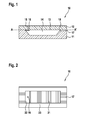
- FIG. 1 shows an exemplary embodiment of the device 10 according to the invention in the form of a sandwich-like layer structure, which comprises a first substrate 11, a second substrate 12 and an expansible layer 13 arranged therebetween, for example a stretchable polymer membrane.
- a chamber 14 Between the first substrate 11 and the second substrate 12 is a chamber 14 through a recess in the first substrate 11, wherein an inside of the chamber 14 is formed by a side of the second substrate 12, on which the layer 13 abuts.
- the second substrate 12 has a first fluid channel 15.
- One end of the first fluid channel 15 forms a first opening 16 in the chamber 14, wherein the first opening 16 is closed by the layer 13.
- the first substrate 11 preferably has a second fluid channel 17, which is fluidically coupled to the chamber 14 via a second opening 18.
- An interior of the chamber 14 is thus bounded by the layer 13 and the first substrate 11 and preferably has a fluidic connection to a second opening 18.
- the side of the second substrate 12 facing the layer 13 partially forms an inner side of the chamber 14 against which the layer 13 rests.
- thermoplastics such as polycarbonate, polypropylene, polyethylene, polymethyl methacrylate, cyclo-olefin polymer or cyclo-olefin copolymer can be used, while the stretchable layer 1 is preferably made of an elastomer, a thermoplastic elastomer, a thermoplastic or a hot-melt adhesive film.
- the thickness of the substrates 11, 12 is preferably between 0.5 and 5 mm, and the thickness of the layer 13 is preferably selected from a range of 5 to 300 ⁇ m.
- the volume of the chamber 14 is preferably between 1 and 1000 ⁇ l.
- the substrates together with required structures such as recesses and channels can preferably be produced by milling, injection molding, hot stamping or laser structuring.
- FIG. 2 shows a cross section corresponding to the in FIG. 1 drawn section line AA 'by the exemplary embodiment of the device according to the invention.
- the layer 13 is connected in a first region 21 with a surface of the second substrate 12 adjoining the layer 13 such that when the first opening 16 is pressurized onto the layer 13, the layer 13 is at a predetermined extent from the surface of the second Substrate 12 in the first region 21 dissolves again.
- the layer 13 is not connected to the second substrate 12.
- the first region 21 and the second region 22 jointly cover the recess in the first substrate 11 and thus together form an inner side of the chamber 14.
- the layer 13 is advantageously connected both to the first substrate 11 and to the second substrate 12.
- the first region 21 is selected to be significantly larger than the second region 22.
- This is advantageously accompanied both by a well-defined arrangement of the layer 13 along the second substrate 12 and a well-defined volume of the chamber 14.
- An influence of gravity which could result in an unwanted expansion of the layer 13 into the interior of the chamber 14, is thereby limited to the significantly smaller second region 22.
- an undesired expansion or bulging of the layer 13 is reduced by an internal stress of the layer 13
- the bonding of the substrates 11, 12 and the layer 13 is preferably carried out by laser transmission welding.
- the wavelength of the laser light is preferably selected from the range between 500 and 1600 nm, more preferably about 10 ⁇ 3 nm, most preferably about 1064 nm.
- the laser can be used in pulse mode or preferably in continuous wave mode.
- the frequency of the laser light is preferably selected from the range between 500 Hz and 500 kHz, more preferably about 4 kHz.
- the power of the laser light is preferably selected from the range between 100 mW and 10,000 mW, more preferably about 700 mW.
- the feed rate of the laser during welding is preferably selected from the range between 1 mm / s and 1000 mm / s, more preferably about 20 mm / s.
- the spot size of the laser beam is preferably selected from the range between 0.05 mm and 10 mm, more preferably about 1 mm.
- FIG. 3 shows the exemplary embodiment of the device 10 according to the invention FIGS. 1 and 2 at different times t1, t2, t3, t4, t5.
- a pressure of a first fluid within the chamber 14 is at least equal to a pressure of a second fluid, preferably gas, in the first fluid channel 15.
- the first fluid is separated from the second fluid by the layer 13.
- the layer 13 is connected in the first region 21 to the surface of the second substrate 12.
- the first opening 16 is located in the chamber 14 in the second region 22 of the layer 13. In the immediate vicinity of the first opening 16, the layer 13 is thus preferably not connected to the substrate 12.
- the pressure in the first fluid channel 15 has been increased, so that a portion 33 of the layer 13 in the second region 22 has expanded into the interior of the chamber 14.
- a part of the located in the chamber 14 second fluid displaced by the second opening 18 in the second fluid channel 17.
- the layer 13 has also partially in the second with a corresponding pressure increase, preferably in the range of a relative pressure of 0.1 to 10 bar, more preferably in the range of 0.5 to 2 bar Region 22 again detached from the second substrate 12.
- the associated enlargement of the extending into the interior of the chamber portion 33 of the layer 13 has displaced further second fluid through the second fluid channel 17.
- an average direction 35, 36, 37, 38 of the extension of the portion 33 of the layer 13 has changed continuously, which successively points to the second opening 18 of the second fluid channel with increasing expansion.
- a direction of the extent of the portion 33 of the layer 13 is advantageously also predetermined as a function of the extent of the part 33.
- the layer 13 has closed the second opening 18, after almost all the second fluid has been displaced through the second fluid channel 17 due to the further expansion of the part 33 of the layer 13.
- FIG. 4 shows a cross section corresponding to the in FIG. 1 drawn section line AA 'by an alternative embodiment of the device according to the invention.
- the layer 13 is connected in a predetermined structure with a surface forming an inner wall of the chamber 14 of the second substrate 12.
- the structure has a sequence of alternating first regions 21 and second regions 22, wherein in the first regions 21, the layer 13 is connected to the inside of the chamber 14 and in the second regions 22, the layer 13 with the inside of the chamber 14th not connected.
- the FIG. 4 shows an example realization of the structure with areas 21, 22 in the form of rectangular strips, wherein all strips have approximately equal lengths, but different widths.
- the local and temporal extent of the part 33 of the layer 13 can be influenced in a targeted manner when pressure is applied through the first opening 18.
- the sizes of the regions 21, 22 are selected such that a quotient of a variable of one of the first regions 21 to a size of one at the respective first region 21 adjacent second region 22 decreases with a to the first opening 16 increasing distance of the respective first and second regions 21, 22.
- This variant of the structure is in FIG. 4 shown. Starting from the first opening 16, the width of the strips of the first regions 21 decreases continuously in the direction of the preferred second fluid channel 17, while the width of the strips of the second regions 22 remains approximately constant.
- the ratio of the size of a first region 21 to the size of an adjacent second region 22 thus decreases the farther the strips are from the first aperture 16.
- the sizes of the regions 21, 22 may be selected such that a quotient of a size of one of the first regions 21 to a size of a second region 22 adjoining the respective first region 21 with a distance of the respective first one increasing from the first opening 16 and the second area 21, 22 increases. This results in a favorable delay expansion of the portion 33 of the layer 13 in the chamber 14 to the sequence.
- FIG. 5 shows a cross section corresponding to the in FIG. 1 drawn section line AA 'by a further alternative embodiment of the device according to the invention.
- the layer 13 is bonded in a predetermined structure to a surface of the second substrate 12, the surface forming an inner wall of the chamber 14.
- the structure has a first region 21, in which the layer 13 is connected to the inside of the chamber 14, and a second region 22, in which the layer 13 is not connected to the inside of the chamber 14.
- the first area 21 has Preferably, the shape of an isosceles triangle whose tip points in the direction of the first opening 16 and the base is arranged in the direction of the preferred second fluid channel 17. When pressure is applied to the layer 13 through the first opening 16, the layer 13 first expands in the second area 22 around the triangular first area 21.
- FIG. 5 illustrated embodiment thus an exemplary way, as by a suitably structured partial connection of the layer 13 with the second substrate 12, a spatial extent of the layer 13 can be influenced.
- a direction of expansion which varies as a function of the extent of the layer 13 can be predetermined.
- the layer 13 which expands into the interior of the chamber 14 can also act on a bag, for example a hose or foil bag, located in the chamber 14.
- a bag for example a hose or foil bag
- targeted pressure can be exerted by the portion 33 of the layer 13 which expands into the interior of the chamber 14 onto a predetermined region of the bag.
- a defined pressure acting on the bag is exceeded, the bag may burst and a substance or a fluid in the bag may be released.
- the average direction 35, 36, 37, 38 of the extension of the portion 33 of the layer 13 is predetermined by suitable structure of the compound so that the portion 33 of the layer 13, the bag only in Partially contacted an area away from the predetermined breaking point.
- the predetermined breaking point is not obscured by the layer 13 and allows uninterrupted emptying of the bag after the pressure exerted by the layer 13 causing bursting of the bag at the predetermined breaking point.
Landscapes
- Chemical & Material Sciences (AREA)
- Health & Medical Sciences (AREA)
- Dispersion Chemistry (AREA)
- Analytical Chemistry (AREA)
- General Health & Medical Sciences (AREA)
- Hematology (AREA)
- Clinical Laboratory Science (AREA)
- Chemical Kinetics & Catalysis (AREA)
- Automatic Analysis And Handling Materials Therefor (AREA)
- Physical Or Chemical Processes And Apparatus (AREA)
- Reciprocating Pumps (AREA)
Applications Claiming Priority (1)
| Application Number | Priority Date | Filing Date | Title |
|---|---|---|---|
| DE102013209866.9A DE102013209866B4 (de) | 2013-05-28 | 2013-05-28 | Vorrichtung mit vorgegebener Fluidverdrängung |
Publications (2)
| Publication Number | Publication Date |
|---|---|
| EP2808082A1 true EP2808082A1 (fr) | 2014-12-03 |
| EP2808082B1 EP2808082B1 (fr) | 2020-02-19 |
Family
ID=50479124
Family Applications (1)
| Application Number | Title | Priority Date | Filing Date |
|---|---|---|---|
| EP14164960.8A Active EP2808082B1 (fr) | 2013-05-28 | 2014-04-16 | Dispositif avec membrane doté d'un refoulement de fluide prédéfini |
Country Status (2)
| Country | Link |
|---|---|
| EP (1) | EP2808082B1 (fr) |
| DE (1) | DE102013209866B4 (fr) |
Cited By (8)
| Publication number | Priority date | Publication date | Assignee | Title |
|---|---|---|---|---|
| EP2905079A1 (fr) * | 2014-02-10 | 2015-08-12 | Robert Bosch Gmbh | Dispositif de stockage préalable d'un fluide dans un système micro-fluidique, procédé de fonctionnement et procédé de fabrication d'un tel dispositif |
| US11597091B2 (en) | 2018-04-30 | 2023-03-07 | BPG Sales and Technology Investments, LLC | Robotic target alignment for vehicle sensor calibration |
| DE102021210723A1 (de) | 2021-09-27 | 2023-03-30 | Robert Bosch Gesellschaft mit beschränkter Haftung | Vorrichtung, insbesondere mikrofluidische Vorrichtung, mit einer Siegelfolie und Verfahren zur Herstellung |
| DE102021210725A1 (de) | 2021-09-27 | 2023-03-30 | Robert Bosch Gesellschaft mit beschränkter Haftung | Vorrichtung, insbesondere mikrofluidische Vorrichtung, mit einer Freiform-Struktur zur Aufnahme von Flüssigkeit |
| DE102021214094A1 (de) | 2021-12-10 | 2023-06-15 | Robert Bosch Gesellschaft mit beschränkter Haftung | Wärmeleitfähige Siegelfolie für eine mikrofluidische Vorrichtung und Herstellverfahren |
| US11781860B2 (en) | 2018-04-30 | 2023-10-10 | BPG Sales and Technology Investments, LLC | Mobile vehicular alignment for sensor calibration |
| US11835646B2 (en) | 2018-04-30 | 2023-12-05 | BPG Sales and Technology Investments, LLC | Target alignment for vehicle sensor calibration |
| US12172654B2 (en) | 2021-01-28 | 2024-12-24 | BPG Sales and Technology Investments, LLC | Target alignment system and method for sensor calibration |
Citations (7)
| Publication number | Priority date | Publication date | Assignee | Title |
|---|---|---|---|---|
| WO2002041994A2 (fr) * | 2000-11-24 | 2002-05-30 | Nextgen Sciences Ltd | Analyses chimiques |
| US20060076068A1 (en) * | 2004-10-13 | 2006-04-13 | Kionix Corporation | Microfluidic pump and valve structures and fabrication methods |
| US20070166199A1 (en) * | 2006-01-19 | 2007-07-19 | Kionix Corporation | Microfluidic systems and control methods |
| EP2025405A1 (fr) * | 2007-07-19 | 2009-02-18 | Formulatrix, Inc. | Ensemble de dosage et procède de distribution des fluides |
| US20110086433A1 (en) * | 2009-10-14 | 2011-04-14 | Jochen Rupp | Microfluidic chip |
| DE102010015161A1 (de) * | 2010-04-16 | 2011-10-20 | Technische Universität Dresden | Mikrofluidiksystem und Verfahren zu dessen Betreiben |
| DE102011078976A1 (de) | 2011-07-11 | 2013-01-17 | Robert Bosch Gmbh | Mikrofluidische Vorrichtung sowie Verfahren zur Herstellung einer mikrofluidischen Vorrichtung |
Family Cites Families (7)
| Publication number | Priority date | Publication date | Assignee | Title |
|---|---|---|---|---|
| US4034756A (en) | 1971-01-13 | 1977-07-12 | Alza Corporation | Osmotically driven fluid dispenser |
| US4558326A (en) | 1982-09-07 | 1985-12-10 | Konishiroku Photo Industry Co., Ltd. | Purging system for ink jet recording apparatus |
| DE19522806C2 (de) | 1995-06-23 | 1997-06-12 | Karlsruhe Forschzent | Verfahren zur Herstellung eines Mikromembranventils |
| US5897097A (en) | 1996-09-06 | 1999-04-27 | Xerox Corporation | Passively addressable fluid valves having S-shaped blocking films |
| EP1163446B1 (fr) | 1998-11-06 | 2007-01-03 | Honeywell Inc. | Reseau de pompage a activation electrostatique |
| US7308991B2 (en) | 2003-11-17 | 2007-12-18 | Advanced Technology Materials, Inc. | Blown bottle with intrinsic liner |
| US7517201B2 (en) | 2005-07-14 | 2009-04-14 | Honeywell International Inc. | Asymmetric dual diaphragm pump |
-
2013
- 2013-05-28 DE DE102013209866.9A patent/DE102013209866B4/de not_active Expired - Fee Related
-
2014
- 2014-04-16 EP EP14164960.8A patent/EP2808082B1/fr active Active
Patent Citations (7)
| Publication number | Priority date | Publication date | Assignee | Title |
|---|---|---|---|---|
| WO2002041994A2 (fr) * | 2000-11-24 | 2002-05-30 | Nextgen Sciences Ltd | Analyses chimiques |
| US20060076068A1 (en) * | 2004-10-13 | 2006-04-13 | Kionix Corporation | Microfluidic pump and valve structures and fabrication methods |
| US20070166199A1 (en) * | 2006-01-19 | 2007-07-19 | Kionix Corporation | Microfluidic systems and control methods |
| EP2025405A1 (fr) * | 2007-07-19 | 2009-02-18 | Formulatrix, Inc. | Ensemble de dosage et procède de distribution des fluides |
| US20110086433A1 (en) * | 2009-10-14 | 2011-04-14 | Jochen Rupp | Microfluidic chip |
| DE102010015161A1 (de) * | 2010-04-16 | 2011-10-20 | Technische Universität Dresden | Mikrofluidiksystem und Verfahren zu dessen Betreiben |
| DE102011078976A1 (de) | 2011-07-11 | 2013-01-17 | Robert Bosch Gmbh | Mikrofluidische Vorrichtung sowie Verfahren zur Herstellung einer mikrofluidischen Vorrichtung |
Cited By (8)
| Publication number | Priority date | Publication date | Assignee | Title |
|---|---|---|---|---|
| EP2905079A1 (fr) * | 2014-02-10 | 2015-08-12 | Robert Bosch Gmbh | Dispositif de stockage préalable d'un fluide dans un système micro-fluidique, procédé de fonctionnement et procédé de fabrication d'un tel dispositif |
| US11597091B2 (en) | 2018-04-30 | 2023-03-07 | BPG Sales and Technology Investments, LLC | Robotic target alignment for vehicle sensor calibration |
| US11781860B2 (en) | 2018-04-30 | 2023-10-10 | BPG Sales and Technology Investments, LLC | Mobile vehicular alignment for sensor calibration |
| US11835646B2 (en) | 2018-04-30 | 2023-12-05 | BPG Sales and Technology Investments, LLC | Target alignment for vehicle sensor calibration |
| US12172654B2 (en) | 2021-01-28 | 2024-12-24 | BPG Sales and Technology Investments, LLC | Target alignment system and method for sensor calibration |
| DE102021210723A1 (de) | 2021-09-27 | 2023-03-30 | Robert Bosch Gesellschaft mit beschränkter Haftung | Vorrichtung, insbesondere mikrofluidische Vorrichtung, mit einer Siegelfolie und Verfahren zur Herstellung |
| DE102021210725A1 (de) | 2021-09-27 | 2023-03-30 | Robert Bosch Gesellschaft mit beschränkter Haftung | Vorrichtung, insbesondere mikrofluidische Vorrichtung, mit einer Freiform-Struktur zur Aufnahme von Flüssigkeit |
| DE102021214094A1 (de) | 2021-12-10 | 2023-06-15 | Robert Bosch Gesellschaft mit beschränkter Haftung | Wärmeleitfähige Siegelfolie für eine mikrofluidische Vorrichtung und Herstellverfahren |
Also Published As
| Publication number | Publication date |
|---|---|
| EP2808082B1 (fr) | 2020-02-19 |
| DE102013209866A1 (de) | 2014-12-18 |
| DE102013209866B4 (de) | 2021-11-04 |
Similar Documents
| Publication | Publication Date | Title |
|---|---|---|
| EP2808082B1 (fr) | Dispositif avec membrane doté d'un refoulement de fluide prédéfini | |
| EP2531760B1 (fr) | Elément structural microfluidique conçu pour la manipulation d'un fluide et puce microfluidique | |
| EP2679307B1 (fr) | Micro-enregistreur, notamment pour l'intégration dans une cellule d'écoulement microfluidique | |
| EP2398589B1 (fr) | Cellule d'écoulement avec réservoir intégré de fluides | |
| EP2687290B1 (fr) | Dispositif de stockage microfluidique pour le stockage préalable d'un fluide, son procédé de fabrication et une utilisation de celui-ci | |
| WO2012048685A1 (fr) | Cellule à circulation | |
| DE10062246C1 (de) | Verfahren und Vorrichtung zur Manipulation kleiner Flüssigkeitsmengen | |
| EP2731721B1 (fr) | Dispositif microfluidique et procédé de production d'un dispositif microfluidique | |
| EP2905079A1 (fr) | Dispositif de stockage préalable d'un fluide dans un système micro-fluidique, procédé de fonctionnement et procédé de fabrication d'un tel dispositif | |
| WO2015044040A1 (fr) | Unité d'analyse pour effectuer une réaction en chaîne par polymérase, procédé pour faire fonctionner une telle unité d'analyse et procédé de fabrication d'une telle unité d'analyse | |
| EP3356041B1 (fr) | Dispositif et procédé de stockage et de vidage de contenants remplis de fluide dans des dispositifs microfluidiques | |
| DE102017122488A1 (de) | Applikator mit einer Dichtungsmembran | |
| DE112014002684T5 (de) | Ventilierter, druckbeaufschlagter gasbetriebener Aktor | |
| EP2552586B1 (fr) | Composant d'un biocapteur et son procédé de fabrication | |
| EP2729251B1 (fr) | Structure microfluidique avec des cavités | |
| DE202014104510U1 (de) | Vorrichtung zum Vorlagern eines Fluids in einem mikrofluidischen System | |
| EP2759751A2 (fr) | Procédé de fabrication d'un clapet anti-retour fermé-normal pour des composants microfluidiques à partir d'un système stratifié polymère et clapet anti-retour | |
| EP2522427A1 (fr) | Dispositif microfluidique et son procédé de fabrication | |
| EP2730336A2 (fr) | Agencement de soupape dans un système microfluidique | |
| EP2072819A1 (fr) | Chambre de pompe et procédé de fabrication de cette chambre | |
| WO2016162146A1 (fr) | Unité de commande | |
| EP4031459B1 (fr) | Soupape pour un contenant d'emballage | |
| EP2624955A1 (fr) | Plateforme microfluidique | |
| EP3183060A1 (fr) | Préstockage de réactifs avec prélèvement défini | |
| WO2000062932A2 (fr) | PROCEDE ET DISPOSITIF POUR DISTRIBUER DE MANIERE DOSEE DES QUANTITES DE LIQUIDES DE L'ORDRE DE 0,1 NL A 100 νL |
Legal Events
| Date | Code | Title | Description |
|---|---|---|---|
| PUAI | Public reference made under article 153(3) epc to a published international application that has entered the european phase |
Free format text: ORIGINAL CODE: 0009012 |
|
| 17P | Request for examination filed |
Effective date: 20140416 |
|
| AK | Designated contracting states |
Kind code of ref document: A1 Designated state(s): AL AT BE BG CH CY CZ DE DK EE ES FI FR GB GR HR HU IE IS IT LI LT LU LV MC MK MT NL NO PL PT RO RS SE SI SK SM TR |
|
| AX | Request for extension of the european patent |
Extension state: BA ME |
|
| R17P | Request for examination filed (corrected) |
Effective date: 20150603 |
|
| RBV | Designated contracting states (corrected) |
Designated state(s): AL AT BE BG CH CY CZ DE DK EE ES FI FR GB GR HR HU IE IS IT LI LT LU LV MC MK MT NL NO PL PT RO RS SE SI SK SM TR |
|
| STAA | Information on the status of an ep patent application or granted ep patent |
Free format text: STATUS: EXAMINATION IS IN PROGRESS |
|
| 17Q | First examination report despatched |
Effective date: 20181012 |
|
| GRAP | Despatch of communication of intention to grant a patent |
Free format text: ORIGINAL CODE: EPIDOSNIGR1 |
|
| STAA | Information on the status of an ep patent application or granted ep patent |
Free format text: STATUS: GRANT OF PATENT IS INTENDED |
|
| INTG | Intention to grant announced |
Effective date: 20191001 |
|
| RAP1 | Party data changed (applicant data changed or rights of an application transferred) |
Owner name: ROBERT BOSCH GMBH |
|
| GRAS | Grant fee paid |
Free format text: ORIGINAL CODE: EPIDOSNIGR3 |
|
| GRAA | (expected) grant |
Free format text: ORIGINAL CODE: 0009210 |
|
| STAA | Information on the status of an ep patent application or granted ep patent |
Free format text: STATUS: THE PATENT HAS BEEN GRANTED |
|
| AK | Designated contracting states |
Kind code of ref document: B1 Designated state(s): AL AT BE BG CH CY CZ DE DK EE ES FI FR GB GR HR HU IE IS IT LI LT LU LV MC MK MT NL NO PL PT RO RS SE SI SK SM TR |
|
| REG | Reference to a national code |
Ref country code: CH Ref legal event code: EP |
|
| REG | Reference to a national code |
Ref country code: DE Ref legal event code: R096 Ref document number: 502014013625 Country of ref document: DE |
|
| REG | Reference to a national code |
Ref country code: AT Ref legal event code: REF Ref document number: 1234320 Country of ref document: AT Kind code of ref document: T Effective date: 20200315 |
|
| REG | Reference to a national code |
Ref country code: IE Ref legal event code: FG4D Free format text: LANGUAGE OF EP DOCUMENT: GERMAN |
|
| RAP2 | Party data changed (patent owner data changed or rights of a patent transferred) |
Owner name: ROBERT BOSCH GMBH |
|
| REG | Reference to a national code |
Ref country code: NL Ref legal event code: MP Effective date: 20200219 |
|
| PG25 | Lapsed in a contracting state [announced via postgrant information from national office to epo] |
Ref country code: FI Free format text: LAPSE BECAUSE OF FAILURE TO SUBMIT A TRANSLATION OF THE DESCRIPTION OR TO PAY THE FEE WITHIN THE PRESCRIBED TIME-LIMIT Effective date: 20200219 Ref country code: RS Free format text: LAPSE BECAUSE OF FAILURE TO SUBMIT A TRANSLATION OF THE DESCRIPTION OR TO PAY THE FEE WITHIN THE PRESCRIBED TIME-LIMIT Effective date: 20200219 Ref country code: NO Free format text: LAPSE BECAUSE OF FAILURE TO SUBMIT A TRANSLATION OF THE DESCRIPTION OR TO PAY THE FEE WITHIN THE PRESCRIBED TIME-LIMIT Effective date: 20200519 |
|
| REG | Reference to a national code |
Ref country code: LT Ref legal event code: MG4D |
|
| PG25 | Lapsed in a contracting state [announced via postgrant information from national office to epo] |
Ref country code: BG Free format text: LAPSE BECAUSE OF FAILURE TO SUBMIT A TRANSLATION OF THE DESCRIPTION OR TO PAY THE FEE WITHIN THE PRESCRIBED TIME-LIMIT Effective date: 20200519 Ref country code: GR Free format text: LAPSE BECAUSE OF FAILURE TO SUBMIT A TRANSLATION OF THE DESCRIPTION OR TO PAY THE FEE WITHIN THE PRESCRIBED TIME-LIMIT Effective date: 20200520 Ref country code: HR Free format text: LAPSE BECAUSE OF FAILURE TO SUBMIT A TRANSLATION OF THE DESCRIPTION OR TO PAY THE FEE WITHIN THE PRESCRIBED TIME-LIMIT Effective date: 20200219 Ref country code: IS Free format text: LAPSE BECAUSE OF FAILURE TO SUBMIT A TRANSLATION OF THE DESCRIPTION OR TO PAY THE FEE WITHIN THE PRESCRIBED TIME-LIMIT Effective date: 20200619 Ref country code: SE Free format text: LAPSE BECAUSE OF FAILURE TO SUBMIT A TRANSLATION OF THE DESCRIPTION OR TO PAY THE FEE WITHIN THE PRESCRIBED TIME-LIMIT Effective date: 20200219 Ref country code: LV Free format text: LAPSE BECAUSE OF FAILURE TO SUBMIT A TRANSLATION OF THE DESCRIPTION OR TO PAY THE FEE WITHIN THE PRESCRIBED TIME-LIMIT Effective date: 20200219 |
|
| PG25 | Lapsed in a contracting state [announced via postgrant information from national office to epo] |
Ref country code: NL Free format text: LAPSE BECAUSE OF FAILURE TO SUBMIT A TRANSLATION OF THE DESCRIPTION OR TO PAY THE FEE WITHIN THE PRESCRIBED TIME-LIMIT Effective date: 20200219 |
|
| PG25 | Lapsed in a contracting state [announced via postgrant information from national office to epo] |
Ref country code: ES Free format text: LAPSE BECAUSE OF FAILURE TO SUBMIT A TRANSLATION OF THE DESCRIPTION OR TO PAY THE FEE WITHIN THE PRESCRIBED TIME-LIMIT Effective date: 20200219 Ref country code: EE Free format text: LAPSE BECAUSE OF FAILURE TO SUBMIT A TRANSLATION OF THE DESCRIPTION OR TO PAY THE FEE WITHIN THE PRESCRIBED TIME-LIMIT Effective date: 20200219 Ref country code: SM Free format text: LAPSE BECAUSE OF FAILURE TO SUBMIT A TRANSLATION OF THE DESCRIPTION OR TO PAY THE FEE WITHIN THE PRESCRIBED TIME-LIMIT Effective date: 20200219 Ref country code: DK Free format text: LAPSE BECAUSE OF FAILURE TO SUBMIT A TRANSLATION OF THE DESCRIPTION OR TO PAY THE FEE WITHIN THE PRESCRIBED TIME-LIMIT Effective date: 20200219 Ref country code: PT Free format text: LAPSE BECAUSE OF FAILURE TO SUBMIT A TRANSLATION OF THE DESCRIPTION OR TO PAY THE FEE WITHIN THE PRESCRIBED TIME-LIMIT Effective date: 20200712 Ref country code: RO Free format text: LAPSE BECAUSE OF FAILURE TO SUBMIT A TRANSLATION OF THE DESCRIPTION OR TO PAY THE FEE WITHIN THE PRESCRIBED TIME-LIMIT Effective date: 20200219 Ref country code: SK Free format text: LAPSE BECAUSE OF FAILURE TO SUBMIT A TRANSLATION OF THE DESCRIPTION OR TO PAY THE FEE WITHIN THE PRESCRIBED TIME-LIMIT Effective date: 20200219 Ref country code: LT Free format text: LAPSE BECAUSE OF FAILURE TO SUBMIT A TRANSLATION OF THE DESCRIPTION OR TO PAY THE FEE WITHIN THE PRESCRIBED TIME-LIMIT Effective date: 20200219 Ref country code: CZ Free format text: LAPSE BECAUSE OF FAILURE TO SUBMIT A TRANSLATION OF THE DESCRIPTION OR TO PAY THE FEE WITHIN THE PRESCRIBED TIME-LIMIT Effective date: 20200219 |
|
| REG | Reference to a national code |
Ref country code: DE Ref legal event code: R097 Ref document number: 502014013625 Country of ref document: DE |
|
| PG25 | Lapsed in a contracting state [announced via postgrant information from national office to epo] |
Ref country code: MC Free format text: LAPSE BECAUSE OF FAILURE TO SUBMIT A TRANSLATION OF THE DESCRIPTION OR TO PAY THE FEE WITHIN THE PRESCRIBED TIME-LIMIT Effective date: 20200219 |
|
| REG | Reference to a national code |
Ref country code: CH Ref legal event code: PL |
|
| PLBE | No opposition filed within time limit |
Free format text: ORIGINAL CODE: 0009261 |
|
| STAA | Information on the status of an ep patent application or granted ep patent |
Free format text: STATUS: NO OPPOSITION FILED WITHIN TIME LIMIT |
|
| 26N | No opposition filed |
Effective date: 20201120 |
|
| PG25 | Lapsed in a contracting state [announced via postgrant information from national office to epo] |
Ref country code: CH Free format text: LAPSE BECAUSE OF NON-PAYMENT OF DUE FEES Effective date: 20200430 Ref country code: LI Free format text: LAPSE BECAUSE OF NON-PAYMENT OF DUE FEES Effective date: 20200430 Ref country code: IT Free format text: LAPSE BECAUSE OF FAILURE TO SUBMIT A TRANSLATION OF THE DESCRIPTION OR TO PAY THE FEE WITHIN THE PRESCRIBED TIME-LIMIT Effective date: 20200219 Ref country code: LU Free format text: LAPSE BECAUSE OF NON-PAYMENT OF DUE FEES Effective date: 20200416 |
|
| REG | Reference to a national code |
Ref country code: BE Ref legal event code: MM Effective date: 20200430 |
|
| PG25 | Lapsed in a contracting state [announced via postgrant information from national office to epo] |
Ref country code: PL Free format text: LAPSE BECAUSE OF FAILURE TO SUBMIT A TRANSLATION OF THE DESCRIPTION OR TO PAY THE FEE WITHIN THE PRESCRIBED TIME-LIMIT Effective date: 20200219 Ref country code: SI Free format text: LAPSE BECAUSE OF FAILURE TO SUBMIT A TRANSLATION OF THE DESCRIPTION OR TO PAY THE FEE WITHIN THE PRESCRIBED TIME-LIMIT Effective date: 20200219 Ref country code: BE Free format text: LAPSE BECAUSE OF NON-PAYMENT OF DUE FEES Effective date: 20200430 |
|
| PG25 | Lapsed in a contracting state [announced via postgrant information from national office to epo] |
Ref country code: IE Free format text: LAPSE BECAUSE OF NON-PAYMENT OF DUE FEES Effective date: 20200416 |
|
| REG | Reference to a national code |
Ref country code: AT Ref legal event code: MM01 Ref document number: 1234320 Country of ref document: AT Kind code of ref document: T Effective date: 20200416 |
|
| PG25 | Lapsed in a contracting state [announced via postgrant information from national office to epo] |
Ref country code: AT Free format text: LAPSE BECAUSE OF NON-PAYMENT OF DUE FEES Effective date: 20200416 |
|
| PG25 | Lapsed in a contracting state [announced via postgrant information from national office to epo] |
Ref country code: TR Free format text: LAPSE BECAUSE OF FAILURE TO SUBMIT A TRANSLATION OF THE DESCRIPTION OR TO PAY THE FEE WITHIN THE PRESCRIBED TIME-LIMIT Effective date: 20200219 Ref country code: MT Free format text: LAPSE BECAUSE OF FAILURE TO SUBMIT A TRANSLATION OF THE DESCRIPTION OR TO PAY THE FEE WITHIN THE PRESCRIBED TIME-LIMIT Effective date: 20200219 Ref country code: CY Free format text: LAPSE BECAUSE OF FAILURE TO SUBMIT A TRANSLATION OF THE DESCRIPTION OR TO PAY THE FEE WITHIN THE PRESCRIBED TIME-LIMIT Effective date: 20200219 |
|
| PG25 | Lapsed in a contracting state [announced via postgrant information from national office to epo] |
Ref country code: MK Free format text: LAPSE BECAUSE OF FAILURE TO SUBMIT A TRANSLATION OF THE DESCRIPTION OR TO PAY THE FEE WITHIN THE PRESCRIBED TIME-LIMIT Effective date: 20200219 Ref country code: AL Free format text: LAPSE BECAUSE OF FAILURE TO SUBMIT A TRANSLATION OF THE DESCRIPTION OR TO PAY THE FEE WITHIN THE PRESCRIBED TIME-LIMIT Effective date: 20200219 |
|
| PGFP | Annual fee paid to national office [announced via postgrant information from national office to epo] |
Ref country code: FR Payment date: 20230417 Year of fee payment: 10 |
|
| PGFP | Annual fee paid to national office [announced via postgrant information from national office to epo] |
Ref country code: GB Payment date: 20230420 Year of fee payment: 10 |
|
| PGFP | Annual fee paid to national office [announced via postgrant information from national office to epo] |
Ref country code: DE Payment date: 20240619 Year of fee payment: 11 |
|
| GBPC | Gb: european patent ceased through non-payment of renewal fee |
Effective date: 20240416 |
|
| PG25 | Lapsed in a contracting state [announced via postgrant information from national office to epo] |
Ref country code: GB Free format text: LAPSE BECAUSE OF NON-PAYMENT OF DUE FEES Effective date: 20240416 |
|
| PG25 | Lapsed in a contracting state [announced via postgrant information from national office to epo] |
Ref country code: FR Free format text: LAPSE BECAUSE OF NON-PAYMENT OF DUE FEES Effective date: 20240430 |
|
| PG25 | Lapsed in a contracting state [announced via postgrant information from national office to epo] |
Ref country code: GB Free format text: LAPSE BECAUSE OF NON-PAYMENT OF DUE FEES Effective date: 20240416 Ref country code: FR Free format text: LAPSE BECAUSE OF NON-PAYMENT OF DUE FEES Effective date: 20240430 |
|
| REG | Reference to a national code |
Ref country code: DE Ref legal event code: R119 Ref document number: 502014013625 Country of ref document: DE |
|
| PG25 | Lapsed in a contracting state [announced via postgrant information from national office to epo] |
Ref country code: DE Free format text: LAPSE BECAUSE OF NON-PAYMENT OF DUE FEES Effective date: 20251104 |