EP1659293A2 - Turbomachine - Google Patents
Turbomachine Download PDFInfo
- Publication number
- EP1659293A2 EP1659293A2 EP05025062A EP05025062A EP1659293A2 EP 1659293 A2 EP1659293 A2 EP 1659293A2 EP 05025062 A EP05025062 A EP 05025062A EP 05025062 A EP05025062 A EP 05025062A EP 1659293 A2 EP1659293 A2 EP 1659293A2
- Authority
- EP
- European Patent Office
- Prior art keywords
- blade
- openings
- hub
- dav
- sko
- Prior art date
- Legal status (The legal status is an assumption and is not a legal conclusion. Google has not performed a legal analysis and makes no representation as to the accuracy of the status listed.)
- Granted
Links
Images


Classifications
-
- F—MECHANICAL ENGINEERING; LIGHTING; HEATING; WEAPONS; BLASTING
- F04—POSITIVE - DISPLACEMENT MACHINES FOR LIQUIDS; PUMPS FOR LIQUIDS OR ELASTIC FLUIDS
- F04D—NON-POSITIVE-DISPLACEMENT PUMPS
- F04D29/00—Details, component parts, or accessories
- F04D29/40—Casings; Connections of working fluid
- F04D29/52—Casings; Connections of working fluid for axial pumps
- F04D29/522—Casings; Connections of working fluid for axial pumps especially adapted for elastic fluid pumps
- F04D29/526—Details of the casing section radially opposing blade tips
-
- F—MECHANICAL ENGINEERING; LIGHTING; HEATING; WEAPONS; BLASTING
- F01—MACHINES OR ENGINES IN GENERAL; ENGINE PLANTS IN GENERAL; STEAM ENGINES
- F01D—NON-POSITIVE DISPLACEMENT MACHINES OR ENGINES, e.g. STEAM TURBINES
- F01D11/00—Preventing or minimising internal leakage of working-fluid, e.g. between stages
- F01D11/08—Preventing or minimising internal leakage of working-fluid, e.g. between stages for sealing space between rotor blade tips and stator
- F01D11/10—Preventing or minimising internal leakage of working-fluid, e.g. between stages for sealing space between rotor blade tips and stator using sealing fluid, e.g. steam
-
- F—MECHANICAL ENGINEERING; LIGHTING; HEATING; WEAPONS; BLASTING
- F01—MACHINES OR ENGINES IN GENERAL; ENGINE PLANTS IN GENERAL; STEAM ENGINES
- F01D—NON-POSITIVE DISPLACEMENT MACHINES OR ENGINES, e.g. STEAM TURBINES
- F01D5/00—Blades; Blade-carrying members; Heating, heat-insulating, cooling or antivibration means on the blades or the members
- F01D5/12—Blades
- F01D5/14—Form or construction
- F01D5/141—Shape, i.e. outer, aerodynamic form
- F01D5/145—Means for influencing boundary layers or secondary circulations
-
- F—MECHANICAL ENGINEERING; LIGHTING; HEATING; WEAPONS; BLASTING
- F04—POSITIVE - DISPLACEMENT MACHINES FOR LIQUIDS; PUMPS FOR LIQUIDS OR ELASTIC FLUIDS
- F04D—NON-POSITIVE-DISPLACEMENT PUMPS
- F04D29/00—Details, component parts, or accessories
- F04D29/66—Combating cavitation, whirls, noise, vibration or the like; Balancing
- F04D29/68—Combating cavitation, whirls, noise, vibration or the like; Balancing by influencing boundary layers
- F04D29/681—Combating cavitation, whirls, noise, vibration or the like; Balancing by influencing boundary layers especially adapted for elastic fluid pumps
- F04D29/682—Combating cavitation, whirls, noise, vibration or the like; Balancing by influencing boundary layers especially adapted for elastic fluid pumps by fluid extraction
-
- F—MECHANICAL ENGINEERING; LIGHTING; HEATING; WEAPONS; BLASTING
- F04—POSITIVE - DISPLACEMENT MACHINES FOR LIQUIDS; PUMPS FOR LIQUIDS OR ELASTIC FLUIDS
- F04D—NON-POSITIVE-DISPLACEMENT PUMPS
- F04D29/00—Details, component parts, or accessories
- F04D29/66—Combating cavitation, whirls, noise, vibration or the like; Balancing
- F04D29/68—Combating cavitation, whirls, noise, vibration or the like; Balancing by influencing boundary layers
- F04D29/681—Combating cavitation, whirls, noise, vibration or the like; Balancing by influencing boundary layers especially adapted for elastic fluid pumps
- F04D29/684—Combating cavitation, whirls, noise, vibration or the like; Balancing by influencing boundary layers especially adapted for elastic fluid pumps by fluid injection
-
- F—MECHANICAL ENGINEERING; LIGHTING; HEATING; WEAPONS; BLASTING
- F04—POSITIVE - DISPLACEMENT MACHINES FOR LIQUIDS; PUMPS FOR LIQUIDS OR ELASTIC FLUIDS
- F04D—NON-POSITIVE-DISPLACEMENT PUMPS
- F04D29/00—Details, component parts, or accessories
- F04D29/66—Combating cavitation, whirls, noise, vibration or the like; Balancing
- F04D29/68—Combating cavitation, whirls, noise, vibration or the like; Balancing by influencing boundary layers
- F04D29/681—Combating cavitation, whirls, noise, vibration or the like; Balancing by influencing boundary layers especially adapted for elastic fluid pumps
- F04D29/685—Inducing localised fluid recirculation in the stator-rotor interface
-
- F—MECHANICAL ENGINEERING; LIGHTING; HEATING; WEAPONS; BLASTING
- F04—POSITIVE - DISPLACEMENT MACHINES FOR LIQUIDS; PUMPS FOR LIQUIDS OR ELASTIC FLUIDS
- F04D—NON-POSITIVE-DISPLACEMENT PUMPS
- F04D27/00—Control, e.g. regulation, of pumps, pumping installations or pumping systems specially adapted for elastic fluids
- F04D27/02—Surge control
- F04D27/0207—Surge control by bleeding, bypassing or recycling fluids
- F04D27/023—Details or means for fluid extraction
-
- F—MECHANICAL ENGINEERING; LIGHTING; HEATING; WEAPONS; BLASTING
- F04—POSITIVE - DISPLACEMENT MACHINES FOR LIQUIDS; PUMPS FOR LIQUIDS OR ELASTIC FLUIDS
- F04D—NON-POSITIVE-DISPLACEMENT PUMPS
- F04D27/00—Control, e.g. regulation, of pumps, pumping installations or pumping systems specially adapted for elastic fluids
- F04D27/02—Surge control
- F04D27/0207—Surge control by bleeding, bypassing or recycling fluids
- F04D27/0238—Details or means for fluid reinjection
-
- Y—GENERAL TAGGING OF NEW TECHNOLOGICAL DEVELOPMENTS; GENERAL TAGGING OF CROSS-SECTIONAL TECHNOLOGIES SPANNING OVER SEVERAL SECTIONS OF THE IPC; TECHNICAL SUBJECTS COVERED BY FORMER USPC CROSS-REFERENCE ART COLLECTIONS [XRACs] AND DIGESTS
- Y02—TECHNOLOGIES OR APPLICATIONS FOR MITIGATION OR ADAPTATION AGAINST CLIMATE CHANGE
- Y02T—CLIMATE CHANGE MITIGATION TECHNOLOGIES RELATED TO TRANSPORTATION
- Y02T50/00—Aeronautics or air transport
- Y02T50/60—Efficient propulsion technologies, e.g. for aircraft
Definitions
- the invention relates to fluid flow machines such as fans, compressors, pumps and fans, both axial, semi-axial and radial.
- the working medium or fluid may be gaseous or liquid.
- the turbomachine according to the invention may comprise one or more stages, usually each with a rotor and a stator; in some cases, the stage is formed only by a rotor.
- the invention relates to a fluid power machine having at least one rotor, the rotor comprising a plurality of rotor blades secured to a rotating shaft. At least one stator may exist, the stator being provided with stationary stator blades. There is a housing which limits the flow of the rotor and the stator with a fluid to the outside.
- the present invention has for its object to provide a fluid flow machine of the type mentioned, which, while avoiding the prior art, a very effective boundary layer control by a dynamic secondary fluid guide, i. a pulsating fluid removal or fluid supply or a temporally changing occurring fluid removal and supply having.
- the rotor consists of a number of blades, which are connected to the rotating shaft of the fluid flow machine and deliver energy to the working fluid.
- a stator consists of a number of stationary blades, which can be designed on the hub side as the housing side with a fixed or free blade end. At least one rotor or stator of the fluid power machine has a free blade end with an adjacent nip.
- the turbomachine may include a stator in front of the first rotor, a so-called leading wheel. Also, at least one stator or Vorleitrad be deviating from the immovable fixation rotatably mounted to change the angle of attack. An adjustment is made for example by a spindle accessible from outside the annular channel.
- the turbomachine may have at least one row of adjustable rotors.
- the fluid flow machine has two counter-rotating waves at Mehrstuftechnik, so that the rotor blade rows change the direction of rotation from stage to stage. There are no stators between successive rotors.
- the turbomachine may also have a bypass configuration such that the single-flow annulus behind a given row of blades divides into two concentric annuli, each of which includes at least one more row of blades.
- a fluid power machine having means for time varying and possibly directional alternating fluid movement between raceway adjacent hub and housing surfaces (LNGO) and blade channel defining surfaces (SKO), with openings or aperture groups distributed along the circumference of LNGO at least one blade row whose centroids are one or more times the blade pitch at the free end of the relevant row of blades from each other and thus form a dynamically operating supply point (DAV).
- DAV dynamically operating supply point
- the openings in LNGO via at least one arranged outside the main flow path chamber and / or conduit with further openings on SKO the same blade row and / or openings at SKO at least one blade of at least one other adjacent row of blades in conjunction.
- fluid is taken from the flow path in the region of the running gap-adjacent hub and housing surface (LNGO).
- the removal takes place at a dynamically operating supply center (DAV).
- the fluid is passed via a conduit and optionally via a chamber, which is interposed in the conduit, wherein the forwarding can take place either against the main flow direction or in the main flow direction.
- the discharge of the fluid takes place on the blade channel limiting surfaces (SKO), wherein the fluid is discharged either through the housing wall or over a surface of a rotor or stator.
- SKO blade channel limiting surfaces
- the possibility of alternately moving the fluid in the line in the opposite direction is created by the oscillating movement of the fluid in the line, so that both of the above-described openings SKO and DAV serve both for the introduction and the removal of fluid.
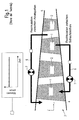
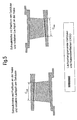
- Fig. 1 shows a highly simplified representation solutions according to the prior art. Shown is a turbomachine having a number of rows of blades, rotors 1 such as stators 2, within the main flow path defined by the annular channel 3, usually a hub 4 (rotor drum) and a housing 5.
- rotors 1 such as stators 2
- the annular channel 3 usually a hub 4 (rotor drum) and a housing 5.
- Existing fluid circulation systems 6 possibly with throttle element 7) achieve an influence on the flow with secondary fluid flows, which remain unchanged in time at a fixed operating point of the turbomachine. This is indicated by a small rectangle symbol in the secondary flow paths and shown graphically in the upper part of the picture.
- the openings for the exchange of the secondary fluid are arranged in known solutions either at locations which are exposed to a constant operating pressure at a given operating point, or are such that pressure fluctuations, as for example at the radial running gap of a rotor without shroud at a certain non-rotating Location of the housing 5 or at the radial gap of a stator without shroud occur at a certain rotating location of the hub 4, not be used for a time-varying secondary fluid transfer. Consequently, those are spent Secondary fluid mass flows unfavorably large, constant in time and directional.
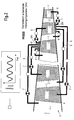
- FIG. 2 shows in greatly simplified representation the flow machine according to the invention, with a number of rows of blades (rotors 1 such as stators 2), within the main flow path 3 (annular channel) through the annular channel 3, usually a hub (rotor drum) and a housing fifth , is limited.
- a supply point for a pressure which varies greatly over time with the blade sequence frequency of the relevant blade row is created by means of specially arranged openings at hub-and-housing surfaces (LNGO) adjoining gap.
- LNGO hub-and-housing surfaces
- This dynamically operating supply point (DAV), which is always provided at the radial gap of the free blade ends, is connected, optionally via a fixed or regulated throttle element, via a line system with openings on the blade channel limiting surfaces (SKO) of one or more blade rows of the fluid flow machine.
- DAV dynamically operating supply point
- the resulting secondary fluid mass flows are small, time varying, and possibly directional alternating. This is indicated by a small rectangle symbol in the secondary flow paths and shown graphically in the upper part of the picture.
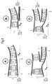
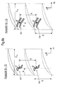
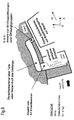
- FIG. 3 shows four possible main flow path configurations of the dynamic self-flow turbomachine of the present invention. Shown is a respective flowed through from left to right annular channel. A rotor drum turns around the marked machine axis. at the embodiments shown in Fig. 3B and 3D, a further rotor drum (hub) is provided. The rotors 1, stators 2 and the Vorleitrad 9 are each labeled, it is shown in a schematic manner, a blade.
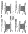
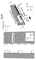
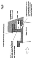
- FIG. 4 shows the definitions of the term of the blade channel limiting surfaces SKO used according to the invention. It is, as can be seen from the caption of Fig. 4, a different arrangement and dimensioning of the individual areas provided. Again, it is simplified to show a row of blades disposed within the main flow path (annular channel 3) between a housing 5 and a hub 4 (rotor drum). Blade channel limiting surfaces according to the present invention are, as shown in Fig.
- FIG. 5 shows the definitions of the term of the running gap-adjacent hub and housing surfaces LNGO used according to the invention. Again, it is shown in simplified form a row of blades arranged within a main flow path (annular channel) between a housing 5 and a hub 4 (rotor drum).
- Laufspaltangrenzende hub and housing surfaces in the context of the present invention as shown in Fig. 5, all surfaces of the inner and outer boundary of the Main flow path (ring channel) of the fluid flow machine, which adjoin the radial gap of a rotor or stator row in the region of the available between front and rear edge position, meridional Schaufelsehendorf (CmG or CmN), and characterized in that between them and the Blades of the relevant blade row is a relative movement.
- Fig. 6a shows the dynamically operating supply point DAV, which represents the basis of all solutions according to the invention. By definition, it is formed on running gap-adjacent surfaces of the hub 4 or the housing 5.
- the left part of the figure shows a corresponding configuration in the plane given by the radial direction r and the axial direction x.
- the running gap is formed between the blade tips of the relevant blade row and the relevant wall. There is a relative movement between the blade tips and the wall.
- the centroids of the individual openings or of the individual opening groups have a distance a from the leading edge which can amount to between 0% and 100% of the meridional leaf tip chord length Cm (0 ⁇ a ⁇ Cm).
- 0.05 * Cm ⁇ a ⁇ 0.40 * Cm make the connection to a separate from the main flow path arrangement of flow channels extending over parts or the entirety of the circumference and connects to SKO upstream or downstream rows of blades.
- FIG. 6b shows alternative arrangements according to the invention in which an opening group occurs at the location of an individual opening, characterized in that each group as such can be unambiguously identified on the basis of the size of the intermediate spaces, has a group-related area centroid F and coincides with one another within a vane passage without overlap Suction or pressure side of two juxtaposed blades can be positioned.
- the shape of the group belonging to the openings is of minor importance and therefore freely selectable. According to the invention, specially shaped holes or slots are possible.
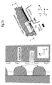
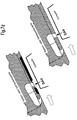
- FIG. 7a shows a solution according to the invention with connection between DAV and a location of the main flow path in front of the same blade row (basic concept A).
- a number of N1 openings establish a connection to an intermediate chamber located outside the main flow path, which may extend over all or part of the periphery.
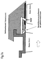
- FIG. 7b shows a particularly simple structural design of the basic concept A.
- the openings of the DAV are designed here as individual drill holes whose axis can be inclined both in the meridian and in the circumferential direction.
- an intermediate chamber is provided which extends along the entire circumference. Upstream of the DAV, the intermediate chamber adjoins openings which are likewise arranged on the main flow path and, in a particularly advantageous embodiment according to the invention, have the shape of a downstream-curved nozzle.
- the curved nozzle is characterized in that the perpendicular of its narrow cross-sectional area encloses an acute angle with the meridian direction.
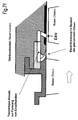
- FIG. 7 c shows the same configuration, but with additional separating bodies for forming individual channels, each leading to a nozzle.
- the cross-section of the intermediate chamber and the connecting channels in the meridian plane can have additional curves, unlike the simple rectangular shape selected here, and the delimiting walls do not have to be arranged parallel or perpendicular to the main flow path.
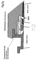
- the openings of the DAV can either, as shown in Figure 7b, c lead by the applied to the wall member on the hub or on the housing squinger, or as shown in Figure 7d, be formed in an embedded in the squish covering projection of the wall member, which is flush with the surface of the Ansteifbelages or radially retracted relative to the squeal.
- the wall material projection is provided at discrete locations or the entire circumference.
- the openings of the DAV can also be formed in a wall provided without any squealer coating.
- FIG. 7e further shows a constructive solution according to the invention for the basic concept A, in which components of the upstream blade row are included.
- This may be an assembly of housing and stator parts (running gap on the rotor) or alternatively an assembly of hub and rotor parts (running gap on the stator 2).
- the openings located upstream of the DAV here again shown as curved nozzles, are formed jointly by housing and stator components (or hub and rotor components).
- the boundary between the components concerned is located anywhere on the nozzle contour.
- Figure 7f shows a related configuration, but with an additional, ideally semi-annular, or annular insert overlapping the nozzle area and having individual channels (separator) matched to the number of nozzles and nozzle shape.
- FIG. 7g furthermore shows a design solution according to the invention for the basic concept A, in which components of the upstream blade row are included.
- the openings located upstream of the DAV again shown here as curved nozzles, are in this variant completely arranged in components of the upstream row of blades and are located at least partially within a passage between two blades.
- This arrangement can also be designed according to the invention with Trenn emotions whatsoever (as Figure 7g shows) or in a simpler manner without Trennmaschinenic.
- FIG. 8 shows the concept of a blade component with circumferential feet and at least one curved nozzle arranged at least partially within the bladed space (blade passage). Characteristic for this purpose is the arrangement of the nozzle downstream of the rear leg of the blade root.
- FIG. 9 shows a solution according to the invention with connection between DAV and SKO of an upstream blade row (basic concept B).
- the bucket suction side has been chosen as SKO.
- a configuration of holes is shown as openings.
- a number of N1 orifices of the DAV connect to an intermediate chamber located outside the main flowpath, which can extend over all or part of the circumference.
- a number of N2> 1 channels establish the connection between the intermediate chamber and the inside of the blade of the upstream blade row. At least one blade of the row is made accessible via one channel each.
- FIG. 10 shows a solution according to the invention with connection between DAV and SKO of a row of blades located in the adjacent main flow path (basic concept C).
- the bucket suction side has been chosen as SKO.
- a configuration of holes is shown as openings.
- a number of N1 openings or groups of openings of the DAV establish a connection to an intermediate chamber located outside the main flow paths 1 and 2, which extend over all or part of the circumference can.
- a number of N2> 1 channels establish the connection between the intermediate chamber and the inside of the blade of the upstream blade row. At least one blade of the series in the main flow path 2 is made accessible via one channel each.
Landscapes
- Engineering & Computer Science (AREA)
- Mechanical Engineering (AREA)
- General Engineering & Computer Science (AREA)
- Physics & Mathematics (AREA)
- Fluid Mechanics (AREA)
- Structures Of Non-Positive Displacement Pumps (AREA)
Applications Claiming Priority (1)
| Application Number | Priority Date | Filing Date | Title |
|---|---|---|---|
| DE102004055439A DE102004055439A1 (de) | 2004-11-17 | 2004-11-17 | Strömungsarbeitsmaschine mit dynamischer Strömungsbeeinflussung |
Publications (3)
| Publication Number | Publication Date |
|---|---|
| EP1659293A2 true EP1659293A2 (fr) | 2006-05-24 |
| EP1659293A3 EP1659293A3 (fr) | 2006-12-20 |
| EP1659293B1 EP1659293B1 (fr) | 2008-03-19 |
Family
ID=35637248
Family Applications (1)
| Application Number | Title | Priority Date | Filing Date |
|---|---|---|---|
| EP05025062A Expired - Lifetime EP1659293B1 (fr) | 2004-11-17 | 2005-11-16 | Turbomachine |
Country Status (3)
| Country | Link |
|---|---|
| US (1) | US8262340B2 (fr) |
| EP (1) | EP1659293B1 (fr) |
| DE (2) | DE102004055439A1 (fr) |
Cited By (11)
| Publication number | Priority date | Publication date | Assignee | Title |
|---|---|---|---|---|
| EP1898067A3 (fr) * | 2006-08-31 | 2008-03-26 | Rolls-Royce Deutschland Ltd & Co KG | Retour de fluide dans un corps séparé de machines de traitement de flux avec une configuration de flux secondaire |
| FR2912789A1 (fr) * | 2007-02-21 | 2008-08-22 | Snecma Sa | Carter avec traitement de carter, compresseur et turbomachine comportant un tel carter. |
| EP2306029A1 (fr) * | 2009-09-28 | 2011-04-06 | General Electric Company | Compresseur et procédé pour contrôler l'écoulement de fluide dans un compresseur |
| EP2072756A3 (fr) * | 2007-12-19 | 2011-05-04 | United Technologies Corporation | Systèmes et procédés incorporant des aubes de section au col variable |
| EP2808558A1 (fr) * | 2013-05-31 | 2014-12-03 | Rolls-Royce Deutschland Ltd & Co KG | Ensemble structurel pour une turbomachine |
| EP2808559A1 (fr) * | 2013-05-31 | 2014-12-03 | Rolls-Royce Deutschland Ltd & Co KG | Ensemble structurel pour une turbomachine |
| EP2808557A1 (fr) * | 2013-05-31 | 2014-12-03 | Rolls-Royce Deutschland Ltd & Co KG | Ensemble structurel pour une turbomachine |
| EP2808556A1 (fr) * | 2013-05-31 | 2014-12-03 | Rolls-Royce Deutschland Ltd & Co KG | Ensemble structurel pour une turbomachine |
| EP2110559A3 (fr) * | 2008-04-18 | 2015-03-25 | Rolls-Royce Deutschland Ltd & Co KG | Turbomachine avec réinjection de fluide pour influencer la couche limite |
| EP2559858A3 (fr) * | 2011-07-14 | 2018-01-10 | Honeywell International Inc. | Compresseurs avec des systèmes de flux d'air secondaires intégrés |
| EP3375984A1 (fr) * | 2017-03-17 | 2018-09-19 | MTU Aero Engines GmbH | Dispositif de circulation pour une turbomachine, procédé de fabrication d'un dispositif de circulation et turbomachine |
Families Citing this family (41)
| Publication number | Priority date | Publication date | Assignee | Title |
|---|---|---|---|---|
| DE102004055439A1 (de) | 2004-11-17 | 2006-05-24 | Rolls-Royce Deutschland Ltd & Co Kg | Strömungsarbeitsmaschine mit dynamischer Strömungsbeeinflussung |
| US8292567B2 (en) * | 2006-09-14 | 2012-10-23 | Caterpillar Inc. | Stator assembly including bleed ports for turbine engine compressor |
| DE102007026455A1 (de) | 2007-06-05 | 2008-12-11 | Rolls-Royce Deutschland Ltd & Co Kg | Strahltriebwerk mit Verdichterluftzirkulation und Verfahren zum Betreiben desselben |
| DE102007037924A1 (de) * | 2007-08-10 | 2009-02-12 | Rolls-Royce Deutschland Ltd & Co Kg | Strömungsarbeitsmaschine mit Ringkanalwandausnehmung |
| US8257016B2 (en) * | 2008-01-23 | 2012-09-04 | Rolls-Royce Deutschland Ltd & Co Kg | Gas turbine with a compressor with self-healing abradable coating |
| DE102008010283A1 (de) * | 2008-02-21 | 2009-08-27 | Mtu Aero Engines Gmbh | Zirkulationsstruktur für einen Turboverdichter |
| DE102008011644A1 (de) * | 2008-02-28 | 2009-09-03 | Rolls-Royce Deutschland Ltd & Co Kg | Gehäusestrukturierung für Axialverdichter im Nabenbereich |
| FR2931906B1 (fr) * | 2008-05-30 | 2017-06-02 | Snecma | Compresseur de turbomachine avec un systeme d'injection d'air. |
| DE102008031982A1 (de) * | 2008-07-07 | 2010-01-14 | Rolls-Royce Deutschland Ltd & Co Kg | Strömungsarbeitsmaschine mit Nut an einem Laufspalt eines Schaufelendes |
| DE102008037154A1 (de) | 2008-08-08 | 2010-02-11 | Rolls-Royce Deutschland Ltd & Co Kg | Strömungsarbeitsmaschine |
| FR2949518B1 (fr) * | 2009-08-31 | 2011-10-21 | Snecma | Compresseur de turbomachine ayant des injecteurs d'air |
| US8545170B2 (en) * | 2009-10-27 | 2013-10-01 | General Electric Company | Turbo machine efficiency equalizer system |
| WO2012052740A1 (fr) * | 2010-10-18 | 2012-04-26 | University Of Durham | Dispositif d'étanchéité pour réduire la fuite de fluide dans une turbine |
| CN102852668B (zh) * | 2011-06-29 | 2015-08-12 | 中国科学院工程热物理研究所 | 一种轴流风扇/压气机自引气喷气机构 |
| DE102011107523B4 (de) * | 2011-07-15 | 2016-08-11 | MTU Aero Engines AG | System zum Einblasen eines Fluids, Verdichter sowie Turbomaschine |
| US9068507B2 (en) * | 2011-11-16 | 2015-06-30 | General Electric Company | Compressor having purge circuit and method of purging |
| EP2696077B1 (fr) * | 2012-08-10 | 2015-07-29 | MTU Aero Engines AG | Compresseur de turbine à gaz avec pompage réduit et méthode associée |
| US20140093355A1 (en) * | 2012-09-28 | 2014-04-03 | United Technologies Corporation | Extended indentation for a fastener within an air flow |
| US9810157B2 (en) * | 2013-03-04 | 2017-11-07 | Pratt & Whitney Canada Corp. | Compressor shroud reverse bleed holes |
| US9726084B2 (en) * | 2013-03-14 | 2017-08-08 | Pratt & Whitney Canada Corp. | Compressor bleed self-recirculating system |
| US9032733B2 (en) | 2013-04-04 | 2015-05-19 | General Electric Company | Turbomachine system with direct header steam injection, related control system and program product |
| DE102013211042B3 (de) * | 2013-06-13 | 2014-08-14 | MTU Aero Engines AG | Flugtriebwerk-Gasturbine |
| US9664118B2 (en) * | 2013-10-24 | 2017-05-30 | General Electric Company | Method and system for controlling compressor forward leakage |
| WO2016093811A1 (fr) * | 2014-12-10 | 2016-06-16 | General Electric Company | Traitement de paroi d'extrémité de compresseur ayant un profil incurvé |
| JP2016118165A (ja) * | 2014-12-22 | 2016-06-30 | 株式会社Ihi | 軸流機械およびジェットエンジン |
| CN105927560B (zh) * | 2016-06-28 | 2018-09-04 | 中国科学院工程热物理研究所 | 一种具有扩稳增效装置的压气机 |
| CN106151113B (zh) * | 2016-07-01 | 2018-07-24 | 中航空天发动机研究院有限公司 | 一种自循环多级轴流压气机 |
| US10876549B2 (en) | 2019-04-05 | 2020-12-29 | Pratt & Whitney Canada Corp. | Tandem stators with flow recirculation conduit |
| CN111810454A (zh) * | 2020-07-17 | 2020-10-23 | 中国航空发动机研究院 | 一种基于自循环振荡射流的机匣、压气机及其扩稳方法 |
| US11268536B1 (en) * | 2020-09-08 | 2022-03-08 | Pratt & Whitney Canada Corp. | Impeller exducer cavity with flow recirculation |
| US11946379B2 (en) | 2021-12-22 | 2024-04-02 | Rolls-Royce North American Technologies Inc. | Turbine engine fan case with manifolded tip injection air recirculation passages |
| US11732612B2 (en) | 2021-12-22 | 2023-08-22 | Rolls-Royce North American Technologies Inc. | Turbine engine fan track liner with tip injection air recirculation passage |
| US11702945B2 (en) | 2021-12-22 | 2023-07-18 | Rolls-Royce North American Technologies Inc. | Turbine engine fan case with tip injection air recirculation passage |
| CN116717373A (zh) * | 2023-05-16 | 2023-09-08 | 中国航发沈阳发动机研究所 | 一种燃气轮机及航空发动机中压气机扩稳设计方法 |
| US12146413B1 (en) | 2023-12-12 | 2024-11-19 | Rolls-Royce North American Technologies Inc. | Circumferentially variable flow control in fan outlet guide vane assemblies for distortion management and stall margin in gas turbine engines |
| US12258870B1 (en) | 2024-03-08 | 2025-03-25 | Rolls-Royce North American Technologies Inc. | Adjustable fan track liner with slotted array active fan tip treatment for distortion tolerance |
| US12286936B1 (en) | 2024-05-09 | 2025-04-29 | Rolls-Royce North American Technologies Inc. | Adjustable fan track liner with groove array active fan tip treatment for distortion tolerance |
| US12215712B1 (en) | 2024-05-09 | 2025-02-04 | Rolls-Royce North American Technologies Inc. | Adjustable fan track liner with dual grooved array active fan tip treatment for distortion tolerance |
| US12209541B1 (en) | 2024-05-09 | 2025-01-28 | Rolls-Royce North American Technologies Inc. | Adjustable fan track liner with dual slotted array active fan tip treatment for distortion tolerance |
| US12168983B1 (en) | 2024-06-28 | 2024-12-17 | Rolls-Royce North American Technologies Inc. | Active fan tip treatment using rotating drum array in fan track liner with axial and circumferential channels for distortion tolerance |
| US12209502B1 (en) | 2024-06-28 | 2025-01-28 | Rolls-Royce North American Technologies Inc. | Active fan tip treatment using rotating drum array with axial channels in fan track liner for distortion tolerance |
Citations (10)
| Publication number | Priority date | Publication date | Assignee | Title |
|---|---|---|---|---|
| US2720356A (en) | 1952-06-12 | 1955-10-11 | John R Erwin | Continuous boundary layer control in compressors |
| US2749027A (en) | 1947-12-26 | 1956-06-05 | Edward A Stalker | Compressor |
| US2870957A (en) | 1947-12-26 | 1959-01-27 | Edward A Stalker | Compressors |
| US2933238A (en) | 1954-06-24 | 1960-04-19 | Edward A Stalker | Axial flow compressors incorporating boundary layer control |
| US3694102A (en) | 1969-07-26 | 1972-09-26 | Daimler Benz Ag | Guide blades of axial compressors |
| US3993414A (en) | 1973-10-23 | 1976-11-23 | Office National D'etudes Et De Recherches Aerospatiales (O.N.E.R.A.) | Supersonic compressors |
| US5480284A (en) | 1993-12-20 | 1996-01-02 | General Electric Company | Self bleeding rotor blade |
| US5690473A (en) | 1992-08-25 | 1997-11-25 | General Electric Company | Turbine blade having transpiration strip cooling and method of manufacture |
| US5904470A (en) | 1997-01-13 | 1999-05-18 | Massachusetts Institute Of Technology | Counter-rotating compressors with control of boundary layers by fluid removal |
| US6334753B1 (en) | 2000-07-31 | 2002-01-01 | United Technologies Corporation | Streamlined bodies with counter-flow fluid injection |
Family Cites Families (58)
| Publication number | Priority date | Publication date | Assignee | Title |
|---|---|---|---|---|
| DE889506C (de) | 1940-09-25 | 1953-09-10 | Versuchsanstalt Fuer Luftfahrt | Stroemungsmaschine mit Grenzschichtabsaugung |
| GB619722A (en) | 1946-12-20 | 1949-03-14 | English Electric Co Ltd | Improvements in and relating to boundary layer control in fluid conduits |
| GB799675A (en) | 1955-10-13 | 1958-08-13 | Bristol Aeroengines Ltd | Improvements in or relating to axial flow gas compressors and turbines |
| US3066912A (en) | 1961-03-28 | 1962-12-04 | Gen Electric | Turbine erosion protective device |
| CH437614A (de) | 1963-07-02 | 1967-11-30 | Moravec Zdenek | Strömungsmaschine mit verminderter Geräuscherzeugung |
| GB987625A (en) | 1963-10-14 | 1965-03-31 | Rolls Royce | Improvements in or relating to axial flow compressors, for example for aircraft gas turbine engines |
| US3572960A (en) | 1969-01-02 | 1971-03-30 | Gen Electric | Reduction of sound in gas turbine engines |
| FR2166494A5 (fr) | 1971-12-27 | 1973-08-17 | Onera (Off Nat Aerospatiale) | |
| US3849023A (en) | 1973-06-28 | 1974-11-19 | Gen Electric | Stator assembly |
| US4155680A (en) | 1977-02-14 | 1979-05-22 | General Electric Company | Compressor protection means |
| GB2017228B (en) | 1977-07-14 | 1982-05-06 | Pratt & Witney Aircraft Of Can | Shroud for a turbine rotor |
| FR2491549B1 (fr) | 1980-10-08 | 1985-07-05 | Snecma | Dispositif de refroidissement d'une turbine a gaz, par prelevement d'air au niveau du compresseur |
| US4479755A (en) * | 1982-04-22 | 1984-10-30 | A/S Kongsberg Vapenfabrikk | Compressor boundary layer bleeding system |
| DE3407946A1 (de) | 1984-03-03 | 1985-09-05 | MTU Motoren- und Turbinen-Union München GmbH, 8000 München | Einrichtung zur verhinderung der ausbreitung von titanfeuer bei turbomaschinen, insbesondere gasturbinen- bzw. gasturbinenstrahltriebwerken |
| DE3407945A1 (de) | 1984-03-03 | 1985-09-05 | MTU Motoren- und Turbinen-Union München GmbH, 8000 München | Verfahren und mittel zur vermeidung der entstehung von titanfeuer |
| US5059093A (en) | 1990-06-07 | 1991-10-22 | United Technologies Corporation | Compressor bleed port |
| US5203162A (en) | 1990-09-12 | 1993-04-20 | United Technologies Corporation | Compressor bleed manifold for a gas turbine engine |
| JPH04132899A (ja) | 1990-09-25 | 1992-05-07 | Mitsubishi Heavy Ind Ltd | 軸流送風機 |
| DE69204861T2 (de) | 1991-01-30 | 1996-05-23 | United Technologies Corp | Ventilatorgehäuse mit Rezirculationskanälen. |
| US5327716A (en) | 1992-06-10 | 1994-07-12 | General Electric Company | System and method for tailoring rotor tip bleed air |
| RU2034175C1 (ru) | 1993-03-11 | 1995-04-30 | Центральный институт авиационного моторостроения им.П.И.Баранова | Турбокомпрессор |
| US5431533A (en) * | 1993-10-15 | 1995-07-11 | United Technologies Corporation | Active vaned passage casing treatment |
| US5562404A (en) * | 1994-12-23 | 1996-10-08 | United Technologies Corporation | Vaned passage hub treatment for cantilever stator vanes |
| US5607284A (en) * | 1994-12-29 | 1997-03-04 | United Technologies Corporation | Baffled passage casing treatment for compressor blades |
| US5474417A (en) | 1994-12-29 | 1995-12-12 | United Technologies Corporation | Cast casing treatment for compressor blades |
| JP3816150B2 (ja) * | 1995-07-18 | 2006-08-30 | 株式会社荏原製作所 | 遠心流体機械 |
| US5762034A (en) | 1996-01-16 | 1998-06-09 | Board Of Trustees Operating Michigan State University | Cooling fan shroud |
| DE19632207A1 (de) | 1996-08-09 | 1998-02-12 | Bmw Rolls Royce Gmbh | Verfahren zur Verhinderung der laminaren Grenzschicht-Ablösung an Turbomaschinen-Schaufeln |
| US6109868A (en) | 1998-12-07 | 2000-08-29 | General Electric Company | Reduced-length high flow interstage air extraction |
| US6231301B1 (en) | 1998-12-10 | 2001-05-15 | United Technologies Corporation | Casing treatment for a fluid compressor |
| US6574965B1 (en) * | 1998-12-23 | 2003-06-10 | United Technologies Corporation | Rotor tip bleed in gas turbine engines |
| DE59912116D1 (de) * | 1999-08-31 | 2005-07-07 | Ltg Ag | Ventilator |
| US6290458B1 (en) | 1999-09-20 | 2001-09-18 | Hitachi, Ltd. | Turbo machines |
| US6302640B1 (en) * | 1999-11-10 | 2001-10-16 | Alliedsignal Inc. | Axial fan skip-stall |
| US6234747B1 (en) | 1999-11-15 | 2001-05-22 | General Electric Company | Rub resistant compressor stage |
| DE10135003C1 (de) | 2001-07-18 | 2002-10-02 | Mtu Aero Engines Gmbh | Verdichtergehäusestruktur |
| US6585479B2 (en) | 2001-08-14 | 2003-07-01 | United Technologies Corporation | Casing treatment for compressors |
| US6663346B2 (en) | 2002-01-17 | 2003-12-16 | United Technologies Corporation | Compressor stator inner diameter platform bleed system |
| WO2003072949A1 (fr) | 2002-02-28 | 2003-09-04 | Mtu Aero Engines Gmbh | Moyens de traitement antiblocage d'extremites pour turbocompresseurs |
| GB0216952D0 (en) | 2002-07-20 | 2002-08-28 | Rolls Royce Plc | Gas turbine engine casing and rotor blade arrangement |
| DE10233032A1 (de) | 2002-07-20 | 2004-01-29 | Rolls-Royce Deutschland Ltd & Co Kg | Strömungsarbeitsmaschine mit integriertem Fluidzirkulationssystem |
| DE10330084B4 (de) * | 2002-08-23 | 2010-06-10 | Mtu Aero Engines Gmbh | Rezirkulationsstruktur für Turboverdichter |
| US7186072B2 (en) | 2002-08-23 | 2007-03-06 | Mtu Aero Engines Gmbh | Recirculation structure for a turbocompressor |
| FR2846034B1 (fr) | 2002-10-22 | 2006-06-23 | Snecma Moteurs | Carter, compresseur, turbine et turbomoteur a combustion comprenant un tel carter |
| GB2408546B (en) | 2003-11-25 | 2006-02-22 | Rolls Royce Plc | A compressor having casing treatment slots |
| DE10355241A1 (de) | 2003-11-26 | 2005-06-30 | Rolls-Royce Deutschland Ltd & Co Kg | Strömungsarbeitsmaschine mit Fluidzufuhr |
| DE10355240A1 (de) | 2003-11-26 | 2005-07-07 | Rolls-Royce Deutschland Ltd & Co Kg | Strömungsarbeitsmaschine mit Fluidentnahme |
| US7097414B2 (en) | 2003-12-16 | 2006-08-29 | Pratt & Whitney Rocketdyne, Inc. | Inducer tip vortex suppressor |
| GB2413158B (en) | 2004-04-13 | 2006-08-16 | Rolls Royce Plc | Flow control arrangement |
| DE102004030597A1 (de) | 2004-06-24 | 2006-01-26 | Rolls-Royce Deutschland Ltd & Co Kg | Strömungsarbeitsmaschine mit Aussenradstrahlerzeugung am Stator |
| DE102004043036A1 (de) | 2004-09-06 | 2006-03-09 | Rolls-Royce Deutschland Ltd & Co Kg | Strömungsarbeitsmaschine mit Fluidentnahme |
| DE102004055439A1 (de) | 2004-11-17 | 2006-05-24 | Rolls-Royce Deutschland Ltd & Co Kg | Strömungsarbeitsmaschine mit dynamischer Strömungsbeeinflussung |
| US7861823B2 (en) | 2005-11-04 | 2011-01-04 | United Technologies Corporation | Duct for reducing shock related noise |
| GB0600532D0 (en) | 2006-01-12 | 2006-02-22 | Rolls Royce Plc | A blade and rotor arrangement |
| EP1862641A1 (fr) | 2006-06-02 | 2007-12-05 | Siemens Aktiengesellschaft | Canal d'écoulement axial pour turbomachine |
| US20080044273A1 (en) | 2006-08-15 | 2008-02-21 | Syed Arif Khalid | Turbomachine with reduced leakage penalties in pressure change and efficiency |
| FR2912789B1 (fr) | 2007-02-21 | 2009-10-02 | Snecma Sa | Carter avec traitement de carter, compresseur et turbomachine comportant un tel carter. |
| US20090160135A1 (en) | 2007-12-20 | 2009-06-25 | Gabriele Turini | Labyrinth seal with reduced leakage flow by grooves and teeth synergistic action |
-
2004
- 2004-11-17 DE DE102004055439A patent/DE102004055439A1/de not_active Withdrawn
-
2005
- 2005-11-16 EP EP05025062A patent/EP1659293B1/fr not_active Expired - Lifetime
- 2005-11-16 DE DE502005003291T patent/DE502005003291D1/de not_active Expired - Lifetime
- 2005-11-17 US US11/280,817 patent/US8262340B2/en not_active Expired - Fee Related
Patent Citations (10)
| Publication number | Priority date | Publication date | Assignee | Title |
|---|---|---|---|---|
| US2749027A (en) | 1947-12-26 | 1956-06-05 | Edward A Stalker | Compressor |
| US2870957A (en) | 1947-12-26 | 1959-01-27 | Edward A Stalker | Compressors |
| US2720356A (en) | 1952-06-12 | 1955-10-11 | John R Erwin | Continuous boundary layer control in compressors |
| US2933238A (en) | 1954-06-24 | 1960-04-19 | Edward A Stalker | Axial flow compressors incorporating boundary layer control |
| US3694102A (en) | 1969-07-26 | 1972-09-26 | Daimler Benz Ag | Guide blades of axial compressors |
| US3993414A (en) | 1973-10-23 | 1976-11-23 | Office National D'etudes Et De Recherches Aerospatiales (O.N.E.R.A.) | Supersonic compressors |
| US5690473A (en) | 1992-08-25 | 1997-11-25 | General Electric Company | Turbine blade having transpiration strip cooling and method of manufacture |
| US5480284A (en) | 1993-12-20 | 1996-01-02 | General Electric Company | Self bleeding rotor blade |
| US5904470A (en) | 1997-01-13 | 1999-05-18 | Massachusetts Institute Of Technology | Counter-rotating compressors with control of boundary layers by fluid removal |
| US6334753B1 (en) | 2000-07-31 | 2002-01-01 | United Technologies Corporation | Streamlined bodies with counter-flow fluid injection |
Non-Patent Citations (2)
| Title |
|---|
| MERCHANT: "Aerodynamic Design and Analysis of a High Pressure Ratio Aspirated Compressor Stage", ASME PAPER 2000- GT-619 |
| SCHULER: "Design, Analysis, Fabrication and Test of an Aspirated Fan Stage", ASME PAPER 2000-GT-618 |
Cited By (21)
| Publication number | Priority date | Publication date | Assignee | Title |
|---|---|---|---|---|
| US8192148B2 (en) | 2006-08-31 | 2012-06-05 | Rolls-Royce Deutschland Ltd & Co Kg | Fluid return in the splitter of turbomachines with bypass-flow configuration |
| EP1898067A3 (fr) * | 2006-08-31 | 2008-03-26 | Rolls-Royce Deutschland Ltd & Co KG | Retour de fluide dans un corps séparé de machines de traitement de flux avec une configuration de flux secondaire |
| FR2912789A1 (fr) * | 2007-02-21 | 2008-08-22 | Snecma Sa | Carter avec traitement de carter, compresseur et turbomachine comportant un tel carter. |
| EP1961920A1 (fr) * | 2007-02-21 | 2008-08-27 | Snecma | Carter avec traitement de carter, compresseur et turbomachine comportant un tel carter |
| US8100629B2 (en) | 2007-02-21 | 2012-01-24 | Snecma | Turbomachine casing with treatment, a compressor, and a turbomachine including such a casing |
| EP2072756A3 (fr) * | 2007-12-19 | 2011-05-04 | United Technologies Corporation | Systèmes et procédés incorporant des aubes de section au col variable |
| US8197209B2 (en) | 2007-12-19 | 2012-06-12 | United Technologies Corp. | Systems and methods involving variable throat area vanes |
| EP2110559A3 (fr) * | 2008-04-18 | 2015-03-25 | Rolls-Royce Deutschland Ltd & Co KG | Turbomachine avec réinjection de fluide pour influencer la couche limite |
| EP2306029A1 (fr) * | 2009-09-28 | 2011-04-06 | General Electric Company | Compresseur et procédé pour contrôler l'écoulement de fluide dans un compresseur |
| US10907503B2 (en) | 2011-07-14 | 2021-02-02 | Honeywell International Inc. | Compressors with integrated secondary air flow systems |
| US10072522B2 (en) | 2011-07-14 | 2018-09-11 | Honeywell International Inc. | Compressors with integrated secondary air flow systems |
| EP2559858A3 (fr) * | 2011-07-14 | 2018-01-10 | Honeywell International Inc. | Compresseurs avec des systèmes de flux d'air secondaires intégrés |
| EP2808557A1 (fr) * | 2013-05-31 | 2014-12-03 | Rolls-Royce Deutschland Ltd & Co KG | Ensemble structurel pour une turbomachine |
| US9587509B2 (en) | 2013-05-31 | 2017-03-07 | Rolls-Royce Deutschland Ltd & Co Kg | Assembly for a fluid flow machine |
| US9664204B2 (en) | 2013-05-31 | 2017-05-30 | Rolls-Royce Deutschland Ltd & Co Kg | Assembly for a fluid flow machine |
| US9822792B2 (en) | 2013-05-31 | 2017-11-21 | Rolls-Royce Deutschland Ltd & Co Kg | Assembly for a fluid flow machine |
| EP2808556A1 (fr) * | 2013-05-31 | 2014-12-03 | Rolls-Royce Deutschland Ltd & Co KG | Ensemble structurel pour une turbomachine |
| US10006467B2 (en) | 2013-05-31 | 2018-06-26 | Rolls-Royce Deutschland Ltd & Co Kg | Assembly for a fluid flow machine |
| EP2808559A1 (fr) * | 2013-05-31 | 2014-12-03 | Rolls-Royce Deutschland Ltd & Co KG | Ensemble structurel pour une turbomachine |
| EP2808558A1 (fr) * | 2013-05-31 | 2014-12-03 | Rolls-Royce Deutschland Ltd & Co KG | Ensemble structurel pour une turbomachine |
| EP3375984A1 (fr) * | 2017-03-17 | 2018-09-19 | MTU Aero Engines GmbH | Dispositif de circulation pour une turbomachine, procédé de fabrication d'un dispositif de circulation et turbomachine |
Also Published As
| Publication number | Publication date |
|---|---|
| EP1659293B1 (fr) | 2008-03-19 |
| US8262340B2 (en) | 2012-09-11 |
| EP1659293A3 (fr) | 2006-12-20 |
| DE102004055439A1 (de) | 2006-05-24 |
| DE502005003291D1 (de) | 2008-04-30 |
| US20060153673A1 (en) | 2006-07-13 |
Similar Documents
| Publication | Publication Date | Title |
|---|---|---|
| EP1659293B1 (fr) | Turbomachine | |
| EP1382855B1 (fr) | Turbomachine avec système de recirculation de fluide intégré | |
| EP2110559B1 (fr) | Turbomachine avec réinjection de fluide pour influencer la couche limite | |
| EP2108784B1 (fr) | Turbomachine dotée d'un composant d'injecteur de fluide | |
| EP2138727B1 (fr) | Bande de recouvrement d'aube dotée d'un passage | |
| EP2249044B1 (fr) | Compresseur ou pompe avec extraction de fluide | |
| DE69515624T2 (de) | Compressorgehäuse mit Rezirkulationskanälen | |
| EP1609999B1 (fr) | Turbo machine | |
| DE602004006922T2 (de) | Leitschaufelanordnung für ein Gasturbinentriebwerk | |
| EP2025945B1 (fr) | Machine de traitement des écoulements dotée d'un creux de paroi de canal de ceinture | |
| EP2226509B1 (fr) | Turbo compresseur ou pompe avec injection de fluide pour influencer la couche limite | |
| EP2808559B1 (fr) | Ensemble structurel pour une turbomachine | |
| DE69936939T2 (de) | Zapfsystem für eine kompressorwand sowie betriebsverfahren | |
| DE4422700A1 (de) | Diffusor für Turbomaschine | |
| CH710476A2 (de) | Verdichter mit einer Axialverdichterendwandeinrichtung zur Steuerung der Leckageströmung in dieser. | |
| EP2808556B1 (fr) | Ensemble structurel pour une turbomachine | |
| EP3064706A1 (fr) | Rangée d'aubes directrices pour une turbomachine traversée axialement | |
| EP1998049A2 (fr) | Aube de machine de travail d'écoulement doté d'une conception à plusieurs profiles | |
| EP1637697B1 (fr) | Passage d'une machine à écoulement avec intervalle axial ayant une concentration inférieure à 1 | |
| EP2993356A1 (fr) | Étage de compresseur radial | |
| DE102016124147B4 (de) | Innenkühlkonfigurationen in Turbinenrotorschaufeln | |
| DE69508198T2 (de) | Ungeteilter Leitkranz für eine Turbomaschine | |
| EP2808557A1 (fr) | Ensemble structurel pour une turbomachine | |
| DE102019220028B4 (de) | Axialturbine | |
| EP4089264A1 (fr) | Agencement d'aubes pour turbines à gaz |
Legal Events
| Date | Code | Title | Description |
|---|---|---|---|
| PUAI | Public reference made under article 153(3) epc to a published international application that has entered the european phase |
Free format text: ORIGINAL CODE: 0009012 |
|
| AK | Designated contracting states |
Kind code of ref document: A2 Designated state(s): AT BE BG CH CY CZ DE DK EE ES FI FR GB GR HU IE IS IT LI LT LU LV MC NL PL PT RO SE SI SK TR |
|
| AX | Request for extension of the european patent |
Extension state: AL BA HR MK YU |
|
| PUAL | Search report despatched |
Free format text: ORIGINAL CODE: 0009013 |
|
| AK | Designated contracting states |
Kind code of ref document: A3 Designated state(s): AT BE BG CH CY CZ DE DK EE ES FI FR GB GR HU IE IS IT LI LT LU LV MC NL PL PT RO SE SI SK TR |
|
| AX | Request for extension of the european patent |
Extension state: AL BA HR MK YU |
|
| 17P | Request for examination filed |
Effective date: 20070405 |
|
| 17Q | First examination report despatched |
Effective date: 20070510 |
|
| GRAC | Information related to communication of intention to grant a patent modified |
Free format text: ORIGINAL CODE: EPIDOSCIGR1 |
|
| GRAP | Despatch of communication of intention to grant a patent |
Free format text: ORIGINAL CODE: EPIDOSNIGR1 |
|
| AKX | Designation fees paid |
Designated state(s): DE FR GB |
|
| RIN1 | Information on inventor provided before grant (corrected) |
Inventor name: GUEMMER, VOLKER |
|
| GRAS | Grant fee paid |
Free format text: ORIGINAL CODE: EPIDOSNIGR3 |
|
| GRAA | (expected) grant |
Free format text: ORIGINAL CODE: 0009210 |
|
| AK | Designated contracting states |
Kind code of ref document: B1 Designated state(s): DE FR GB |
|
| REG | Reference to a national code |
Ref country code: GB Ref legal event code: FG4D Free format text: NOT ENGLISH |
|
| REF | Corresponds to: |
Ref document number: 502005003291 Country of ref document: DE Date of ref document: 20080430 Kind code of ref document: P |
|
| ET | Fr: translation filed | ||
| PLBE | No opposition filed within time limit |
Free format text: ORIGINAL CODE: 0009261 |
|
| STAA | Information on the status of an ep patent application or granted ep patent |
Free format text: STATUS: NO OPPOSITION FILED WITHIN TIME LIMIT |
|
| 26N | No opposition filed |
Effective date: 20081222 |
|
| REG | Reference to a national code |
Ref country code: DE Ref legal event code: R082 Ref document number: 502005003291 Country of ref document: DE Representative=s name: HOEFER & PARTNER, DE |
|
| REG | Reference to a national code |
Ref country code: DE Ref legal event code: R082 Ref document number: 502005003291 Country of ref document: DE Representative=s name: HOEFER & PARTNER, DE Effective date: 20130402 Ref country code: DE Ref legal event code: R081 Ref document number: 502005003291 Country of ref document: DE Owner name: ROLLS-ROYCE DEUTSCHLAND LTD & CO KG, DE Free format text: FORMER OWNER: ROLLS-ROYCE DEUTSCHLAND LTD & CO KG, 15827 BLANKENFELDE, DE Effective date: 20130402 Ref country code: DE Ref legal event code: R082 Ref document number: 502005003291 Country of ref document: DE Representative=s name: HOEFER & PARTNER PATENTANWAELTE MBB, DE Effective date: 20130402 |
|
| REG | Reference to a national code |
Ref country code: FR Ref legal event code: PLFP Year of fee payment: 11 |
|
| REG | Reference to a national code |
Ref country code: FR Ref legal event code: PLFP Year of fee payment: 12 |
|
| REG | Reference to a national code |
Ref country code: FR Ref legal event code: PLFP Year of fee payment: 13 |
|
| PGFP | Annual fee paid to national office [announced via postgrant information from national office to epo] |
Ref country code: DE Payment date: 20191127 Year of fee payment: 15 |
|
| PGFP | Annual fee paid to national office [announced via postgrant information from national office to epo] |
Ref country code: FR Payment date: 20191125 Year of fee payment: 15 |
|
| PGFP | Annual fee paid to national office [announced via postgrant information from national office to epo] |
Ref country code: GB Payment date: 20191127 Year of fee payment: 15 |
|
| REG | Reference to a national code |
Ref country code: DE Ref legal event code: R119 Ref document number: 502005003291 Country of ref document: DE |
|
| GBPC | Gb: european patent ceased through non-payment of renewal fee |
Effective date: 20201116 |
|
| PG25 | Lapsed in a contracting state [announced via postgrant information from national office to epo] |
Ref country code: FR Free format text: LAPSE BECAUSE OF NON-PAYMENT OF DUE FEES Effective date: 20201130 |
|
| PG25 | Lapsed in a contracting state [announced via postgrant information from national office to epo] |
Ref country code: GB Free format text: LAPSE BECAUSE OF NON-PAYMENT OF DUE FEES Effective date: 20201116 Ref country code: DE Free format text: LAPSE BECAUSE OF NON-PAYMENT OF DUE FEES Effective date: 20210601 |