EP2808558A1 - Ensemble structurel pour une turbomachine - Google Patents
Ensemble structurel pour une turbomachine Download PDFInfo
- Publication number
- EP2808558A1 EP2808558A1 EP14170065.8A EP14170065A EP2808558A1 EP 2808558 A1 EP2808558 A1 EP 2808558A1 EP 14170065 A EP14170065 A EP 14170065A EP 2808558 A1 EP2808558 A1 EP 2808558A1
- Authority
- EP
- European Patent Office
- Prior art keywords
- flow path
- main flow
- support member
- plug
- secondary flow
- Prior art date
- Legal status (The legal status is an assumption and is not a legal conclusion. Google has not performed a legal analysis and makes no representation as to the accuracy of the status listed.)
- Granted
Links
- 230000000295 complement effect Effects 0.000 claims description 2
- 239000012530 fluid Substances 0.000 description 22
- 239000000243 solution Substances 0.000 description 7
- 238000011282 treatment Methods 0.000 description 7
- 238000004519 manufacturing process Methods 0.000 description 4
- 230000000712 assembly Effects 0.000 description 2
- 238000000429 assembly Methods 0.000 description 2
- 230000015572 biosynthetic process Effects 0.000 description 2
- 238000002347 injection Methods 0.000 description 2
- 239000007924 injection Substances 0.000 description 2
- 230000000149 penetrating effect Effects 0.000 description 2
- 238000011144 upstream manufacturing Methods 0.000 description 2
- 238000005266 casting Methods 0.000 description 1
- 230000002401 inhibitory effect Effects 0.000 description 1
- 239000007788 liquid Substances 0.000 description 1
- 238000003754 machining Methods 0.000 description 1
- 230000004048 modification Effects 0.000 description 1
- 238000012986 modification Methods 0.000 description 1
- 238000000926 separation method Methods 0.000 description 1
- 238000007493 shaping process Methods 0.000 description 1
- 238000005245 sintering Methods 0.000 description 1
- 229910000679 solder Inorganic materials 0.000 description 1
Images


Classifications
-
- F—MECHANICAL ENGINEERING; LIGHTING; HEATING; WEAPONS; BLASTING
- F01—MACHINES OR ENGINES IN GENERAL; ENGINE PLANTS IN GENERAL; STEAM ENGINES
- F01D—NON-POSITIVE DISPLACEMENT MACHINES OR ENGINES, e.g. STEAM TURBINES
- F01D17/00—Regulating or controlling by varying flow
- F01D17/10—Final actuators
- F01D17/105—Final actuators by passing part of the fluid
-
- F—MECHANICAL ENGINEERING; LIGHTING; HEATING; WEAPONS; BLASTING
- F04—POSITIVE - DISPLACEMENT MACHINES FOR LIQUIDS; PUMPS FOR LIQUIDS OR ELASTIC FLUIDS
- F04D—NON-POSITIVE-DISPLACEMENT PUMPS
- F04D29/00—Details, component parts, or accessories
- F04D29/40—Casings; Connections of working fluid
- F04D29/52—Casings; Connections of working fluid for axial pumps
- F04D29/522—Casings; Connections of working fluid for axial pumps especially adapted for elastic fluid pumps
- F04D29/526—Details of the casing section radially opposing blade tips
-
- F—MECHANICAL ENGINEERING; LIGHTING; HEATING; WEAPONS; BLASTING
- F04—POSITIVE - DISPLACEMENT MACHINES FOR LIQUIDS; PUMPS FOR LIQUIDS OR ELASTIC FLUIDS
- F04D—NON-POSITIVE-DISPLACEMENT PUMPS
- F04D29/00—Details, component parts, or accessories
- F04D29/40—Casings; Connections of working fluid
- F04D29/52—Casings; Connections of working fluid for axial pumps
- F04D29/54—Fluid-guiding means, e.g. diffusers
- F04D29/541—Specially adapted for elastic fluid pumps
-
- F—MECHANICAL ENGINEERING; LIGHTING; HEATING; WEAPONS; BLASTING
- F04—POSITIVE - DISPLACEMENT MACHINES FOR LIQUIDS; PUMPS FOR LIQUIDS OR ELASTIC FLUIDS
- F04D—NON-POSITIVE-DISPLACEMENT PUMPS
- F04D29/00—Details, component parts, or accessories
- F04D29/66—Combating cavitation, whirls, noise, vibration or the like; Balancing
- F04D29/68—Combating cavitation, whirls, noise, vibration or the like; Balancing by influencing boundary layers
- F04D29/681—Combating cavitation, whirls, noise, vibration or the like; Balancing by influencing boundary layers especially adapted for elastic fluid pumps
- F04D29/685—Inducing localised fluid recirculation in the stator-rotor interface
-
- F—MECHANICAL ENGINEERING; LIGHTING; HEATING; WEAPONS; BLASTING
- F05—INDEXING SCHEMES RELATING TO ENGINES OR PUMPS IN VARIOUS SUBCLASSES OF CLASSES F01-F04
- F05D—INDEXING SCHEME FOR ASPECTS RELATING TO NON-POSITIVE-DISPLACEMENT MACHINES OR ENGINES, GAS-TURBINES OR JET-PROPULSION PLANTS
- F05D2260/00—Function
- F05D2260/15—Load balancing
-
- F—MECHANICAL ENGINEERING; LIGHTING; HEATING; WEAPONS; BLASTING
- F05—INDEXING SCHEMES RELATING TO ENGINES OR PUMPS IN VARIOUS SUBCLASSES OF CLASSES F01-F04
- F05D—INDEXING SCHEME FOR ASPECTS RELATING TO NON-POSITIVE-DISPLACEMENT MACHINES OR ENGINES, GAS-TURBINES OR JET-PROPULSION PLANTS
- F05D2260/00—Function
- F05D2260/60—Fluid transfer
- F05D2260/606—Bypassing the fluid
-
- F—MECHANICAL ENGINEERING; LIGHTING; HEATING; WEAPONS; BLASTING
- F05—INDEXING SCHEMES RELATING TO ENGINES OR PUMPS IN VARIOUS SUBCLASSES OF CLASSES F01-F04
- F05D—INDEXING SCHEME FOR ASPECTS RELATING TO NON-POSITIVE-DISPLACEMENT MACHINES OR ENGINES, GAS-TURBINES OR JET-PROPULSION PLANTS
- F05D2270/00—Control
- F05D2270/01—Purpose of the control system
- F05D2270/17—Purpose of the control system to control boundary layer
Definitions
- the invention relates to a structural assembly for a turbomachine according to the preamble of patent claim 1.
- turbomachines in particular of fluid flow machines such as fans, compressors, pumps and fans, is limited by the growth and separation of boundary layers in the rotor and stator tip region near the housing or hub wall. In the case of blade rows with a running gap, this leads to high secondary losses and possibly to the occurrence of operational instabilities at higher loads.
- casing treatments As a countermeasure, it is known to use so-called casing treatments.
- the simplest form of casing treatments are circumferential grooves with a rectangular or parallelogram-shaped cross-section, as used, for example, in US Pat EP 0 754 864 A1 are disclosed.
- Other solutions provide for rows of slots or openings in the housing, the individual slots / openings being oriented substantially in the flow direction and having a slender shape with a small extension viewed in the circumferential direction of the machine. Such solutions are for example in the DE 101 35 003 C1 disclosed.
- a fluid flow machine which forms at least one secondary flow channel in the area of the blade leading edge in a main flow path boundary, which connects two openings arranged on the main flow path boundary.
- Each secondary flow channel in each case connects a removal opening with a supply opening provided further upstream.
- the present invention is based on the object to provide a structural assembly, which efficiently secondary flow channels, including those of complex shape, in the field of Main flow path boundary of a turbomachine (ie in the region of the housing or the hub) can provide.
- the structural assembly has at least one support member and at least one directly or indirectly connected to the support member, replaceable plug.
- the neck is directly connected to the support member, e.g. arranged on the circumference of the support member, or the connecting piece is connected to a component connected to the support member and thus indirectly to the support member.
- the replaceable plug comprises a subsection of a secondary flow channel, the subsection completing at least one further subsection of the secondary flow channel extending outside of the plug in the structural assembly to a secondary flow passage continuous between its openings.
- the solution according to the invention has the advantage that the secondary flow channel can be interrupted or varied by replacing the plug. Also, in the event of wear, a portion of the secondary flow channel formed in the plug can be replaced in a simple manner. In the plug simultaneously spatially compact and robust three-dimensional structures of a secondary flow channel can be provided.
- the invention thus contemplates a portion of the main flowpath of a turbomachine, in the region of a free end and a nip row of blades, in which a series of circumferentially distributed secondary flow channels are provided.
- the course of the secondary flow channels can each be spatially complex.
- a structural assembly is provided for structurally implementing said secondary flow channels.
- the replaceable plug penetrates at least one structural component which overhangs the main flow path and which is the support component or a further component.
- the support component forms at least part of the main flow path boundary with at least part of its surfaces.
- the replaceable plug extends in a substantially radial direction relative to the main flow path and forms an end face which forms part of the main flow path boundary. According to one embodiment, at least one of the openings of the secondary flow channel is formed in the end face of the replaceable plug.
- At least one subsection of a secondary flow channel is realized in the support component, so that at least the support component and the plug accommodate subsections of the secondary flow channel. Further sections can be provided by further components.
- the support member is formed as an annular housing or as a half-shell housing a turbomachine, or the support member is formed like a ring or half-ring on the hub of a turbomachine.
- the support member is structurally such that for the purpose of assembly and disassembly of the interchangeable plug from the main flow path side facing a direct access to the interchangeable plug is given, so that the interchangeable plug from the main flow path side facing away from the support member without disassembling others Structural components is replaceable.
- the structural assembly according to the invention further comprises at least one insert member, wherein in the support member is provided a circumferentially extending recess which receives along the circumference at least one insert member, and wherein each insert member forms part of the surfaces of a part of the Hauptströmungspfaderbandung and at least forms a portion of a secondary flow channel.
- the insert member is completely penetrated at the periphery of at least one replaceable plug, such that the end face of the replaceable plug forms part of the Hauptströmungspfadberandung. It can also be provided that the replaceable plug penetrates only the insert component and there has a defined seat, wherein the support member is a local Has recess through which the replaceable plug in the insert component is mounted and dismounted. Alternatively, the replaceable plug penetrates both the support member and the insert member.
- the structural assembly according to the invention further comprises at least one connecting member, wherein the connecting member substantially on the side facing away from the main flow path side of the support member to the support member, and wherein the connecting member forms at least a portion of a secondary flow channel.
- the support member is completely penetrated at the periphery of at least one replaceable plug such that the end face of the replaceable plug forms part of the main flow path boundary, wherein portions of a secondary flow channel are formed in the support member, in the connection member and in the replaceable plug and complement each other to a continuous secondary flow channel.
- a further variant of the invention provides that the connecting component is installed in recesses in the support component in the area of at least one end of the secondary flow channel and in this way directly adjoins the main flow path.
- the connecting component thus also forms an opening-near region of the secondary flow channel.
- At least one connecting piece may be formed on the side of the support component facing away from the main flow path on the circumference of the support component. Also, on the side facing away from the main flow path side of the support member is at least one, at least along a portion of the circumference continuously extending web for receiving at least one interchangeable plug is formed.
- the replaceable plug is designed as a multi-part element.
- an embodiment variant provides that the replaceable plug is subdivided into partial plugs along at least partial sections of the secondary flow channel.
- a further embodiment provides that the replaceable plug is formed in two parts and provided a fixing top plug and a example with a defined seat Understop comprises, with upper and lower plugs together form the interchangeable plug.
- the fixation of the interchangeable plug is realized by a fit, a press fit, a plug, a clamp or a screw.
- the interchangeable plug with implemented portion of a secondary flow channel may be replaced by a blind plug with no channel implemented for the purpose of inhibiting flow through the secondary flow channel.
- the present invention relates generally to structural assemblies for turbomachines, such as turbines, and to particular fluid flow machines, such as fans, compressors, pumps, and fans, in both axial, semi-axial, and radial designs.
- the working medium or fluid may be gaseous or liquid.
- the turbomachine may include one or more stages each having a rotor and a stator. In some cases, the stage is formed only by a rotor.
- the rotor of a turbomachine in which a structural assembly according to the invention is used, consists of a number of blades, which are connected to the rotating shaft of the turbomachine and deliver energy to the working fluid in the case of the fluid flow machine.
- the rotor can be designed with or without shroud on the outer blade end.
- the stator of a turbomachine in which a structural assembly according to the invention is used, consists of a number of stationary blades, which can be designed on the hub side as the housing side with a fixed or free blade end.
- the rotor drum and the blading are usually surrounded by a housing. In other cases, z. As in propellers or propellers, no housing exists.
- a turbomachine in which a structural assembly according to the invention is used, can also have a stator in front of the first rotor, a so-called leading wheel. At least one stator or Vorleitrad - may be rotatably mounted - deviating from an immovable fixation - to change the angle of attack can. A Adjustment takes place for example by a spindle accessible from outside the annular channel.
- a turbomachine in which a structural assembly according to the invention is used, have at least one row of adjustable rotors.
- a turbomachine in which a structural assembly according to the invention is used in multi-stage have two opposing waves, so that the rotor blade rows change the direction of rotation from stage to stage. There are no stators between successive rotors.
- a turbomachine in which a structural assembly according to the invention is used have a bypass configuration such that a single-flow annular channel behind a certain row of blades divides into two concentric annular channels, which in turn accommodate at least one more row of blades.
- turbomachine in which a structural assembly according to the invention is used, it is, for example, a jet engine, in particular a turbofan engine.
- the structural assembly is formed, for example, in the region of a compressor of a jet engine or turbofan engine.
- the invention further relates to a fluid flow machine with a structural assembly according to the invention.
- the Fig. 2A shows an arrangement of a blade row 3 with free end and running gap 5 in the meridian plane formed by the axial direction x and the radial direction r.
- the nip 5 separates the blade tip from a component 2 belonging to the main flow path at the hub or housing of the fluid flow machine.
- the component 2 forms a main flow path boundary 4 toward the main flow path.
- the main flow direction in the main flow path is indicated by an arrow A. Upstream and / or downstream of the row of blades 3 with running gap, further rows of blades may be located.
- Within the main flow path belonging to the component 2 is in the region of the running gap 5 a number of the circumference distributed secondary flow channels 1 are provided, which each form an opening at their ends (feed opening and removal opening).
- Fig. 2A shows the outline or the projection of a single secondary flow channel 1 in the meridian plane (xr).
- xr meridian plane
- each channel 1 has a three-dimensional spatially twisted course, which in the Fig. 2B is shown by way of example.
- cross-sectional shape of the secondary flow channels 1 in the Fig. 2B merely exemplified as rectangular.
- the cross section of the secondary flow channels 1 may be formed in other embodiments without corners, in particular circular or elliptical.
- FIG. 3A shows a structural assembly according to the invention in the region of a row of blades with running gap in the meridian view (xr).
- the main flow direction is indicated by an arrow A.
- the blade row is no longer shown in favor of a simpler representation.
- At least one secondary flow channel 1 is formed, which has two openings 111, 112 in the main flow path boundary 4 and is connected via this to the main flow path.
- the secondary flow channel 11 is designed as a single-path path with an opening through which fluid flows from the main flow channel into the secondary flow channel 1 and a second opening, through which the fluid leaves the secondary flow channel 1.
- At least one of the secondary flow channels is formed by an arrangement in which a single channel is divided along its course into at least two subchannels, thereby forming a kind of "trouser configuration".
- an inflow port and a plurality of outflow ports are included, which belong to the secondary flow passage.
- at least one of the secondary flow channels is formed by an arrangement in which at least two Channels are merged into a channel, in which case a plurality of inflow and a discharge port to the secondary flow passage.
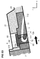
- the secondary flow channel 1 is realized in a structural assembly comprising a support member 21, an insert member 22 and a replaceable plug 6.
- the support member 21 is formed as an annular housing of a turbomachine or as a half shell housing a turbomachine. With a corresponding arrangement in the hub region, it is, for example, annularly formed on the hub of a turbomachine or semi-annular on the hub of a turbomachine.
- a recess extending in the circumferential direction is provided, in which at least one insert member 22 is inserted along the circumference.
- the insert component 21 forms part of its surfaces with a part of the main flow path boundary 4.
- the replaceable plug 6 extends in a substantially radial direction with respect to the main flow path, penetrating both the support member 21 and the insert member 22.
- the plug 6 has an end face 60 which forms part of the main flow path boundary 4.
- the secondary flow channel 1 comprises two subsections 11, 12, wherein one subsection 11 is formed in the insert component 22 and the other subsection 12 is formed in the interchangeable plug 6.
- the one of the two openings 111, 112 of the secondary flow channel 1 is in the insert member 22 and the other of the openings 111, 112 of the secondary flow channel 1 is in Plug 6 is formed.
- the insert member 22 is inserted in the axial direction in the corresponding recess in the support member 21.
- a fixation of the components 21, 22 to each other in the axial direction can be effected by a further component 7.
- portion 12 of the secondary flow channel 1 is provided by means of internal surfaces of the plug 6, that is not by means of structures formed on the outside of the plug 6.
- a portion 12 of the secondary flow channel 1 in a replaceable plug 6 is associated with the advantage that it is possible by replacing the plug 6 by a blind plug without integrated channel section, to prevent the flow through the secondary flow channel 1.
- a flow through a secondary flow channel can be switched on and off.
- various plugs 6 in which the partial section 12 realized in the stopper 6 is embodied in different ways, in each case complementing the partial section 11 formed in the insert component 22. In this way, the formation of the secondary flow channel 1 and the flow occurring therein can be varied in a simple manner.
- FIG. 3B shows a further embodiment of a structural assembly in the region of a row of blades with running gap in the meridian view (xr).
- the embodiment of FIG. 3B differs from the embodiment of FIG. 3A in that the replaceable plug 6 is designed as a multipart element.
- the plug 6 is divided into two sub-plugs 61, 62, wherein in principle more than two sub-plugs are possible.
- the plug 6 comprises a fixing top plug 62 and a properly fitted bottom plug 61 Part region 12 of the secondary flow channel 1 in the lower plug 61 is formed.
- the top plug 62 is fixed by screwing or the like in a corresponding opening of the support member 21, for example.
- FIG. 3C shows a further embodiment of a structural assembly in the region of a row of blades with running gap in the meridian view (xr).
- this embodiment is different from the embodiments of FIGS. 3A and 3B provided that the replaceable plug 6 penetrates only the insert member 22 and is fitted in this. A structural member penetrating the plug 6 is thus provided solely by the insert member 22.
- the support member 21 has a local recess 215, for example in the form of a mounting opening through which the replaceable plug 6 in the insert member 22 can be mounted and dismounted. It can be provided, for example, that the plug 6 has a round cross section and is fixed by means of a thread 63 in its upper part in the insert member 22.
- the shape and fixation modes of the replaceable plug 6 may be formed in other ways.
- the Figure 3D shows a further embodiment of a structural assembly in the region of a row of blades with running gap in the meridian view (xr).
- the replaceable plug 6 penetrates again alone the insert member 22, wherein above the plug 6 in the support member 21, a mounting opening 215 is formed.
- the plug 6 is designed as a multi-part element with two partial plugs 64, 65, whereby more than two partial plugs can be provided.
- the subdivision of the plug 6 into two sub-plugs 64, 65 takes place along two sections of the secondary flow channel 1, that is, each of the two sub-plugs 64, 65 accommodates a lower portion 12a, 12b of the portion 12 realized in the plug 6. This is associated with the advantage in that the secondary flow channel 1 can be made more easily accessible, for example, to a production tool.
- the exchangeable plug 6 may be provided to produce the exchangeable plug 6 by means of a casting, sintering or print production method. This applies to all described embodiments.
- FIG. 3E shows a further embodiment of a structural assembly in the region of a row of blades with running gap in the meridian view (xr).
- the secondary flow channel 1 comprises three subsections 11, 12, 13, wherein a subsection is formed in a support member 21, a subsection in a replaceable plug 6, and a subsection in a connection component 23.
- the support member 21 forms with part of its surfaces a part of the main flow path boundary 4. At the side facing away from the main flow path, it forms a structure 212 for receiving the replaceable plug 6, which is formed in the illustrated embodiment by a cylindrical wall or a nozzle 212. In the wall 212 of the plug 6 is inserted, wherein the end face 60 of the plug 6 is a part of the Hauptströmungspfadberandung 4. In the plug 6, a portion 12 of the secondary flow channel and one of the openings 111 of the secondary flow channel are integrated.
- the support member 21 further includes on its side facing away from the main flow path side a web 211, in which a first portion 13 of the secondary flow channel is formed. Between the web 211 and the neck or the wall 212 extends the connecting member 22 which extends on the side facing away from the main flow path side of the support member 21 between these portions 211, 212 of the support member 21 and is arranged, for example as a line freely in space.
- a fixation of the replaceable plug 6 can be realized for example by a fit, a press fit, a plug, a clamp or a screw.
- the connecting member 11 is attached to the web 211 and the nozzle 212, for example, by a fit, a plug, a clamp, a screw, a weld or a solder.
- the connecting member 23 is formed such that it is inserted in recesses in the support member 21 in the region of at least one end of the secondary flow channel and in this way has surfaces which form part of the Hauptströmungspfadberandung 4.
- the connecting piece 211 is formed as part of the connecting component 23.
- FIGS. 3A to 3E the constructive solutions, with regard to FIGS. 3A to 3E are described, combined with each other.
- a multipart plug 6 in the embodiment of the FIG. 3E be realized.
- the invention is not limited in its embodiment to the embodiments shown above, which are to be understood only as examples.
- shape and configuration of the secondary flow channels and of the components providing them can be realized in a different way than illustrated.
Landscapes
- Engineering & Computer Science (AREA)
- Mechanical Engineering (AREA)
- General Engineering & Computer Science (AREA)
- Structures Of Non-Positive Displacement Pumps (AREA)
Applications Claiming Priority (1)
| Application Number | Priority Date | Filing Date | Title |
|---|---|---|---|
| DE102013210171.6A DE102013210171A1 (de) | 2013-05-31 | 2013-05-31 | Strukturbaugruppe für eine Strömungsmaschine |
Publications (2)
| Publication Number | Publication Date |
|---|---|
| EP2808558A1 true EP2808558A1 (fr) | 2014-12-03 |
| EP2808558B1 EP2808558B1 (fr) | 2017-12-06 |
Family
ID=50842103
Family Applications (1)
| Application Number | Title | Priority Date | Filing Date |
|---|---|---|---|
| EP14170065.8A Not-in-force EP2808558B1 (fr) | 2013-05-31 | 2014-05-27 | Ensemble structurel pour une turbomachine |
Country Status (3)
| Country | Link |
|---|---|
| US (1) | US9587509B2 (fr) |
| EP (1) | EP2808558B1 (fr) |
| DE (1) | DE102013210171A1 (fr) |
Families Citing this family (3)
| Publication number | Priority date | Publication date | Assignee | Title |
|---|---|---|---|---|
| DE102018116062A1 (de) * | 2018-07-03 | 2020-01-09 | Rolls-Royce Deutschland Ltd & Co Kg | Strukturbaugruppe für einen Verdichter einer Strömungsmaschine |
| US10876549B2 (en) | 2019-04-05 | 2020-12-29 | Pratt & Whitney Canada Corp. | Tandem stators with flow recirculation conduit |
| CN113027817A (zh) * | 2021-03-12 | 2021-06-25 | 西北工业大学 | 一种轴流压气机自循环机匣的加工方法及其结构 |
Citations (11)
| Publication number | Priority date | Publication date | Assignee | Title |
|---|---|---|---|---|
| EP0497574A1 (fr) | 1991-01-30 | 1992-08-05 | United Technologies Corporation | Virole avec canaux de récirculation pour soufflante |
| EP0754864A1 (fr) | 1995-07-18 | 1997-01-22 | Ebara Corporation | Turbomachine |
| DE10105456A1 (de) * | 2001-02-07 | 2002-08-08 | Daimler Chrysler Ag | Verdichter, insbesondere für eine Brennkraftmaschine |
| DE10135003C1 (de) | 2001-07-18 | 2002-10-02 | Mtu Aero Engines Gmbh | Verdichtergehäusestruktur |
| US6585479B2 (en) | 2001-08-14 | 2003-07-01 | United Technologies Corporation | Casing treatment for compressors |
| DE10330084A1 (de) | 2002-08-23 | 2004-03-04 | Mtu Aero Engines Gmbh | Rezirkulationsstruktur für Turboverdichter |
| US20050226717A1 (en) | 2004-04-13 | 2005-10-13 | Rolls-Royce Plc | Flow control arrangement |
| EP1659293A2 (fr) * | 2004-11-17 | 2006-05-24 | Rolls-Royce Deutschland Ltd & Co KG | Turbomachine |
| EP2108784A2 (fr) * | 2008-04-08 | 2009-10-14 | Rolls-Royce Deutschland Ltd & Co KG | Turbomachine dotée d'un composant d'injecteur de fluide |
| DE102008037154A1 (de) | 2008-08-08 | 2010-02-11 | Rolls-Royce Deutschland Ltd & Co Kg | Strömungsarbeitsmaschine |
| US20120201654A1 (en) * | 2009-08-31 | 2012-08-09 | Snecma | Turbine engine compressor having air injections |
Family Cites Families (5)
| Publication number | Priority date | Publication date | Assignee | Title |
|---|---|---|---|---|
| DE1503581B1 (de) * | 1965-05-04 | 1970-12-17 | Maschf Augsburg Nuernberg Ag | Mit Abgasturbo-Aufladung betriebene Zweitakt-Brennkraftmaschine |
| US5562404A (en) * | 1994-12-23 | 1996-10-08 | United Technologies Corporation | Vaned passage hub treatment for cantilever stator vanes |
| US5586859A (en) * | 1995-05-31 | 1996-12-24 | United Technologies Corporation | Flow aligned plenum endwall treatment for compressor blades |
| IL130799A (en) * | 1999-07-05 | 2003-10-31 | Israel Aircraft Ind Ltd | Adapter for use in exhaust gas temperature measurement of a jet engine |
| DE102004030597A1 (de) | 2004-06-24 | 2006-01-26 | Rolls-Royce Deutschland Ltd & Co Kg | Strömungsarbeitsmaschine mit Aussenradstrahlerzeugung am Stator |
-
2013
- 2013-05-31 DE DE102013210171.6A patent/DE102013210171A1/de not_active Withdrawn
-
2014
- 2014-05-27 EP EP14170065.8A patent/EP2808558B1/fr not_active Not-in-force
- 2014-05-28 US US14/289,318 patent/US9587509B2/en not_active Expired - Fee Related
Patent Citations (12)
| Publication number | Priority date | Publication date | Assignee | Title |
|---|---|---|---|---|
| EP0497574A1 (fr) | 1991-01-30 | 1992-08-05 | United Technologies Corporation | Virole avec canaux de récirculation pour soufflante |
| EP0754864A1 (fr) | 1995-07-18 | 1997-01-22 | Ebara Corporation | Turbomachine |
| DE10105456A1 (de) * | 2001-02-07 | 2002-08-08 | Daimler Chrysler Ag | Verdichter, insbesondere für eine Brennkraftmaschine |
| DE10135003C1 (de) | 2001-07-18 | 2002-10-02 | Mtu Aero Engines Gmbh | Verdichtergehäusestruktur |
| US6585479B2 (en) | 2001-08-14 | 2003-07-01 | United Technologies Corporation | Casing treatment for compressors |
| DE10330084A1 (de) | 2002-08-23 | 2004-03-04 | Mtu Aero Engines Gmbh | Rezirkulationsstruktur für Turboverdichter |
| US20050226717A1 (en) | 2004-04-13 | 2005-10-13 | Rolls-Royce Plc | Flow control arrangement |
| EP1659293A2 (fr) * | 2004-11-17 | 2006-05-24 | Rolls-Royce Deutschland Ltd & Co KG | Turbomachine |
| EP2108784A2 (fr) * | 2008-04-08 | 2009-10-14 | Rolls-Royce Deutschland Ltd & Co KG | Turbomachine dotée d'un composant d'injecteur de fluide |
| US8152445B2 (en) | 2008-04-08 | 2012-04-10 | Rolls-Royce Deutschland Ltd & Co Kg | Fluid flow machine with fluid injector assembly |
| DE102008037154A1 (de) | 2008-08-08 | 2010-02-11 | Rolls-Royce Deutschland Ltd & Co Kg | Strömungsarbeitsmaschine |
| US20120201654A1 (en) * | 2009-08-31 | 2012-08-09 | Snecma | Turbine engine compressor having air injections |
Also Published As
| Publication number | Publication date |
|---|---|
| US20140363277A1 (en) | 2014-12-11 |
| EP2808558B1 (fr) | 2017-12-06 |
| US9587509B2 (en) | 2017-03-07 |
| DE102013210171A1 (de) | 2014-12-04 |
Similar Documents
| Publication | Publication Date | Title |
|---|---|---|
| EP2808559B1 (fr) | Ensemble structurel pour une turbomachine | |
| EP2108784B1 (fr) | Turbomachine dotée d'un composant d'injecteur de fluide | |
| EP2808556B1 (fr) | Ensemble structurel pour une turbomachine | |
| EP1382855B1 (fr) | Turbomachine avec système de recirculation de fluide intégré | |
| EP1898067B1 (fr) | Retour de fluide dans un corps séparé de machines de traitement de flux avec une configuration de flux secondaire | |
| EP2179143B1 (fr) | Refroidissement de fente entre une paroi de chambre de combustion et une paroi de turbine d'une installation de turbine à gaz | |
| EP3287611B1 (fr) | Turbine à gaz | |
| EP3428393B1 (fr) | Roue aubagée d'une turbomachine | |
| DE102004030597A1 (de) | Strömungsarbeitsmaschine mit Aussenradstrahlerzeugung am Stator | |
| DE102007037924A1 (de) | Strömungsarbeitsmaschine mit Ringkanalwandausnehmung | |
| EP2110559A2 (fr) | Turbomachine avec réinjection de fluide pour influencer la couche limite | |
| EP2921716B1 (fr) | Groupe de série d'aubes | |
| EP3409899B1 (fr) | Dispositif de joint d'étanchéité pourvu de tôle d'étanchéité assemblée par soudage, turbomachine et procédé de fabrication | |
| EP2818724B1 (fr) | Turbomachine et procédé | |
| EP3236011B1 (fr) | Rotor comprenant un porte à faux sur les pales pour un élément de sécurité | |
| EP2846000B1 (fr) | Roue statorique d'une turbine à gaz | |
| EP3431708B1 (fr) | Dispositif d'écoulement environnant, turbomachine et application associée | |
| EP2808557A1 (fr) | Ensemble structurel pour une turbomachine | |
| EP2808558B1 (fr) | Ensemble structurel pour une turbomachine | |
| DE102012215413B4 (de) | Baugruppe einer Axialturbomaschine | |
| EP3321589B1 (fr) | Buse de carburant d'une turbine à gaz dotée du générateur de tourbillons | |
| DE112020000728B4 (de) | Hochtemperaturkomponente und herstellungsverfahren für hochtemperaturkomponente | |
| EP3004562B1 (fr) | Elément d'insertion et turbine à gaz | |
| EP3022395B1 (fr) | Elément d'insertion et turbine à gaz | |
| EP4069947B1 (fr) | Support de joint d'étanchéité conçu pour une turbomachine et comportant des orifices en forme d'encoche dans le corps de joint d'étanchéité et turbine à gaz |
Legal Events
| Date | Code | Title | Description |
|---|---|---|---|
| PUAI | Public reference made under article 153(3) epc to a published international application that has entered the european phase |
Free format text: ORIGINAL CODE: 0009012 |
|
| 17P | Request for examination filed |
Effective date: 20140527 |
|
| AK | Designated contracting states |
Kind code of ref document: A1 Designated state(s): AL AT BE BG CH CY CZ DE DK EE ES FI FR GB GR HR HU IE IS IT LI LT LU LV MC MK MT NL NO PL PT RO RS SE SI SK SM TR |
|
| AX | Request for extension of the european patent |
Extension state: BA ME |
|
| R17P | Request for examination filed (corrected) |
Effective date: 20150602 |
|
| RBV | Designated contracting states (corrected) |
Designated state(s): AL AT BE BG CH CY CZ DE DK EE ES FI FR GB GR HR HU IE IS IT LI LT LU LV MC MK MT NL NO PL PT RO RS SE SI SK SM TR |
|
| GRAP | Despatch of communication of intention to grant a patent |
Free format text: ORIGINAL CODE: EPIDOSNIGR1 |
|
| RIC1 | Information provided on ipc code assigned before grant |
Ipc: F04D 29/54 20060101ALN20170630BHEP Ipc: F04D 29/52 20060101AFI20170630BHEP Ipc: F04D 29/68 20060101ALI20170630BHEP |
|
| INTG | Intention to grant announced |
Effective date: 20170720 |
|
| RIN1 | Information on inventor provided before grant (corrected) |
Inventor name: DR. GUEMMER, VOLKER |
|
| GRAS | Grant fee paid |
Free format text: ORIGINAL CODE: EPIDOSNIGR3 |
|
| GRAA | (expected) grant |
Free format text: ORIGINAL CODE: 0009210 |
|
| AK | Designated contracting states |
Kind code of ref document: B1 Designated state(s): AL AT BE BG CH CY CZ DE DK EE ES FI FR GB GR HR HU IE IS IT LI LT LU LV MC MK MT NL NO PL PT RO RS SE SI SK SM TR |
|
| REG | Reference to a national code |
Ref country code: GB Ref legal event code: FG4D Free format text: NOT ENGLISH |
|
| REG | Reference to a national code |
Ref country code: AT Ref legal event code: REF Ref document number: 952645 Country of ref document: AT Kind code of ref document: T Effective date: 20171215 Ref country code: CH Ref legal event code: EP |
|
| REG | Reference to a national code |
Ref country code: IE Ref legal event code: FG4D Free format text: LANGUAGE OF EP DOCUMENT: GERMAN |
|
| REG | Reference to a national code |
Ref country code: DE Ref legal event code: R096 Ref document number: 502014006456 Country of ref document: DE |
|
| REG | Reference to a national code |
Ref country code: NL Ref legal event code: MP Effective date: 20171206 |
|
| REG | Reference to a national code |
Ref country code: LT Ref legal event code: MG4D |
|
| PG25 | Lapsed in a contracting state [announced via postgrant information from national office to epo] |
Ref country code: LT Free format text: LAPSE BECAUSE OF FAILURE TO SUBMIT A TRANSLATION OF THE DESCRIPTION OR TO PAY THE FEE WITHIN THE PRESCRIBED TIME-LIMIT Effective date: 20171206 Ref country code: NO Free format text: LAPSE BECAUSE OF FAILURE TO SUBMIT A TRANSLATION OF THE DESCRIPTION OR TO PAY THE FEE WITHIN THE PRESCRIBED TIME-LIMIT Effective date: 20180306 Ref country code: SE Free format text: LAPSE BECAUSE OF FAILURE TO SUBMIT A TRANSLATION OF THE DESCRIPTION OR TO PAY THE FEE WITHIN THE PRESCRIBED TIME-LIMIT Effective date: 20171206 Ref country code: ES Free format text: LAPSE BECAUSE OF FAILURE TO SUBMIT A TRANSLATION OF THE DESCRIPTION OR TO PAY THE FEE WITHIN THE PRESCRIBED TIME-LIMIT Effective date: 20171206 Ref country code: FI Free format text: LAPSE BECAUSE OF FAILURE TO SUBMIT A TRANSLATION OF THE DESCRIPTION OR TO PAY THE FEE WITHIN THE PRESCRIBED TIME-LIMIT Effective date: 20171206 |
|
| REG | Reference to a national code |
Ref country code: FR Ref legal event code: PLFP Year of fee payment: 5 |
|
| PG25 | Lapsed in a contracting state [announced via postgrant information from national office to epo] |
Ref country code: RS Free format text: LAPSE BECAUSE OF FAILURE TO SUBMIT A TRANSLATION OF THE DESCRIPTION OR TO PAY THE FEE WITHIN THE PRESCRIBED TIME-LIMIT Effective date: 20171206 Ref country code: BG Free format text: LAPSE BECAUSE OF FAILURE TO SUBMIT A TRANSLATION OF THE DESCRIPTION OR TO PAY THE FEE WITHIN THE PRESCRIBED TIME-LIMIT Effective date: 20180306 Ref country code: HR Free format text: LAPSE BECAUSE OF FAILURE TO SUBMIT A TRANSLATION OF THE DESCRIPTION OR TO PAY THE FEE WITHIN THE PRESCRIBED TIME-LIMIT Effective date: 20171206 Ref country code: LV Free format text: LAPSE BECAUSE OF FAILURE TO SUBMIT A TRANSLATION OF THE DESCRIPTION OR TO PAY THE FEE WITHIN THE PRESCRIBED TIME-LIMIT Effective date: 20171206 Ref country code: GR Free format text: LAPSE BECAUSE OF FAILURE TO SUBMIT A TRANSLATION OF THE DESCRIPTION OR TO PAY THE FEE WITHIN THE PRESCRIBED TIME-LIMIT Effective date: 20180307 |
|
| PG25 | Lapsed in a contracting state [announced via postgrant information from national office to epo] |
Ref country code: NL Free format text: LAPSE BECAUSE OF FAILURE TO SUBMIT A TRANSLATION OF THE DESCRIPTION OR TO PAY THE FEE WITHIN THE PRESCRIBED TIME-LIMIT Effective date: 20171206 |
|
| PG25 | Lapsed in a contracting state [announced via postgrant information from national office to epo] |
Ref country code: SK Free format text: LAPSE BECAUSE OF FAILURE TO SUBMIT A TRANSLATION OF THE DESCRIPTION OR TO PAY THE FEE WITHIN THE PRESCRIBED TIME-LIMIT Effective date: 20171206 Ref country code: CZ Free format text: LAPSE BECAUSE OF FAILURE TO SUBMIT A TRANSLATION OF THE DESCRIPTION OR TO PAY THE FEE WITHIN THE PRESCRIBED TIME-LIMIT Effective date: 20171206 Ref country code: EE Free format text: LAPSE BECAUSE OF FAILURE TO SUBMIT A TRANSLATION OF THE DESCRIPTION OR TO PAY THE FEE WITHIN THE PRESCRIBED TIME-LIMIT Effective date: 20171206 |
|
| PG25 | Lapsed in a contracting state [announced via postgrant information from national office to epo] |
Ref country code: PL Free format text: LAPSE BECAUSE OF FAILURE TO SUBMIT A TRANSLATION OF THE DESCRIPTION OR TO PAY THE FEE WITHIN THE PRESCRIBED TIME-LIMIT Effective date: 20171206 Ref country code: SM Free format text: LAPSE BECAUSE OF FAILURE TO SUBMIT A TRANSLATION OF THE DESCRIPTION OR TO PAY THE FEE WITHIN THE PRESCRIBED TIME-LIMIT Effective date: 20171206 Ref country code: RO Free format text: LAPSE BECAUSE OF FAILURE TO SUBMIT A TRANSLATION OF THE DESCRIPTION OR TO PAY THE FEE WITHIN THE PRESCRIBED TIME-LIMIT Effective date: 20171206 Ref country code: IT Free format text: LAPSE BECAUSE OF FAILURE TO SUBMIT A TRANSLATION OF THE DESCRIPTION OR TO PAY THE FEE WITHIN THE PRESCRIBED TIME-LIMIT Effective date: 20171206 |
|
| REG | Reference to a national code |
Ref country code: DE Ref legal event code: R097 Ref document number: 502014006456 Country of ref document: DE |
|
| PG25 | Lapsed in a contracting state [announced via postgrant information from national office to epo] |
Ref country code: MT Free format text: LAPSE BECAUSE OF FAILURE TO SUBMIT A TRANSLATION OF THE DESCRIPTION OR TO PAY THE FEE WITHIN THE PRESCRIBED TIME-LIMIT Effective date: 20171206 |
|
| PLBE | No opposition filed within time limit |
Free format text: ORIGINAL CODE: 0009261 |
|
| STAA | Information on the status of an ep patent application or granted ep patent |
Free format text: STATUS: NO OPPOSITION FILED WITHIN TIME LIMIT |
|
| 26N | No opposition filed |
Effective date: 20180907 |
|
| PG25 | Lapsed in a contracting state [announced via postgrant information from national office to epo] |
Ref country code: SI Free format text: LAPSE BECAUSE OF FAILURE TO SUBMIT A TRANSLATION OF THE DESCRIPTION OR TO PAY THE FEE WITHIN THE PRESCRIBED TIME-LIMIT Effective date: 20171206 Ref country code: DK Free format text: LAPSE BECAUSE OF FAILURE TO SUBMIT A TRANSLATION OF THE DESCRIPTION OR TO PAY THE FEE WITHIN THE PRESCRIBED TIME-LIMIT Effective date: 20171206 |
|
| REG | Reference to a national code |
Ref country code: CH Ref legal event code: PL |
|
| REG | Reference to a national code |
Ref country code: BE Ref legal event code: MM Effective date: 20180531 |
|
| PG25 | Lapsed in a contracting state [announced via postgrant information from national office to epo] |
Ref country code: MC Free format text: LAPSE BECAUSE OF FAILURE TO SUBMIT A TRANSLATION OF THE DESCRIPTION OR TO PAY THE FEE WITHIN THE PRESCRIBED TIME-LIMIT Effective date: 20171206 |
|
| REG | Reference to a national code |
Ref country code: IE Ref legal event code: MM4A |
|
| PG25 | Lapsed in a contracting state [announced via postgrant information from national office to epo] |
Ref country code: CH Free format text: LAPSE BECAUSE OF NON-PAYMENT OF DUE FEES Effective date: 20180531 Ref country code: LI Free format text: LAPSE BECAUSE OF NON-PAYMENT OF DUE FEES Effective date: 20180531 |
|
| PG25 | Lapsed in a contracting state [announced via postgrant information from national office to epo] |
Ref country code: LU Free format text: LAPSE BECAUSE OF NON-PAYMENT OF DUE FEES Effective date: 20180527 |
|
| PG25 | Lapsed in a contracting state [announced via postgrant information from national office to epo] |
Ref country code: IE Free format text: LAPSE BECAUSE OF NON-PAYMENT OF DUE FEES Effective date: 20180527 |
|
| PG25 | Lapsed in a contracting state [announced via postgrant information from national office to epo] |
Ref country code: BE Free format text: LAPSE BECAUSE OF NON-PAYMENT OF DUE FEES Effective date: 20180531 |
|
| PG25 | Lapsed in a contracting state [announced via postgrant information from national office to epo] |
Ref country code: TR Free format text: LAPSE BECAUSE OF FAILURE TO SUBMIT A TRANSLATION OF THE DESCRIPTION OR TO PAY THE FEE WITHIN THE PRESCRIBED TIME-LIMIT Effective date: 20171206 |
|
| PG25 | Lapsed in a contracting state [announced via postgrant information from national office to epo] |
Ref country code: PT Free format text: LAPSE BECAUSE OF FAILURE TO SUBMIT A TRANSLATION OF THE DESCRIPTION OR TO PAY THE FEE WITHIN THE PRESCRIBED TIME-LIMIT Effective date: 20171206 Ref country code: HU Free format text: LAPSE BECAUSE OF FAILURE TO SUBMIT A TRANSLATION OF THE DESCRIPTION OR TO PAY THE FEE WITHIN THE PRESCRIBED TIME-LIMIT; INVALID AB INITIO Effective date: 20140527 |
|
| PG25 | Lapsed in a contracting state [announced via postgrant information from national office to epo] |
Ref country code: CY Free format text: LAPSE BECAUSE OF FAILURE TO SUBMIT A TRANSLATION OF THE DESCRIPTION OR TO PAY THE FEE WITHIN THE PRESCRIBED TIME-LIMIT Effective date: 20171206 Ref country code: MK Free format text: LAPSE BECAUSE OF NON-PAYMENT OF DUE FEES Effective date: 20171206 |
|
| PG25 | Lapsed in a contracting state [announced via postgrant information from national office to epo] |
Ref country code: AL Free format text: LAPSE BECAUSE OF FAILURE TO SUBMIT A TRANSLATION OF THE DESCRIPTION OR TO PAY THE FEE WITHIN THE PRESCRIBED TIME-LIMIT Effective date: 20171206 Ref country code: IS Free format text: LAPSE BECAUSE OF FAILURE TO SUBMIT A TRANSLATION OF THE DESCRIPTION OR TO PAY THE FEE WITHIN THE PRESCRIBED TIME-LIMIT Effective date: 20180406 |
|
| PGFP | Annual fee paid to national office [announced via postgrant information from national office to epo] |
Ref country code: FR Payment date: 20200527 Year of fee payment: 7 |
|
| REG | Reference to a national code |
Ref country code: AT Ref legal event code: MM01 Ref document number: 952645 Country of ref document: AT Kind code of ref document: T Effective date: 20190527 |
|
| PGFP | Annual fee paid to national office [announced via postgrant information from national office to epo] |
Ref country code: GB Payment date: 20200528 Year of fee payment: 7 |
|
| PGFP | Annual fee paid to national office [announced via postgrant information from national office to epo] |
Ref country code: DE Payment date: 20200728 Year of fee payment: 7 |
|
| PG25 | Lapsed in a contracting state [announced via postgrant information from national office to epo] |
Ref country code: AT Free format text: LAPSE BECAUSE OF NON-PAYMENT OF DUE FEES Effective date: 20190527 |
|
| REG | Reference to a national code |
Ref country code: DE Ref legal event code: R119 Ref document number: 502014006456 Country of ref document: DE |
|
| GBPC | Gb: european patent ceased through non-payment of renewal fee |
Effective date: 20210527 |
|
| PG25 | Lapsed in a contracting state [announced via postgrant information from national office to epo] |
Ref country code: GB Free format text: LAPSE BECAUSE OF NON-PAYMENT OF DUE FEES Effective date: 20210527 Ref country code: DE Free format text: LAPSE BECAUSE OF NON-PAYMENT OF DUE FEES Effective date: 20211201 |
|
| PG25 | Lapsed in a contracting state [announced via postgrant information from national office to epo] |
Ref country code: FR Free format text: LAPSE BECAUSE OF NON-PAYMENT OF DUE FEES Effective date: 20210531 |