EP2808659A1 - Kraftstofffüllstandsmessung mit Messsystem im Tank - Google Patents
Kraftstofffüllstandsmessung mit Messsystem im Tank Download PDFInfo
- Publication number
- EP2808659A1 EP2808659A1 EP14168193.2A EP14168193A EP2808659A1 EP 2808659 A1 EP2808659 A1 EP 2808659A1 EP 14168193 A EP14168193 A EP 14168193A EP 2808659 A1 EP2808659 A1 EP 2808659A1
- Authority
- EP
- European Patent Office
- Prior art keywords
- fuel
- tank
- output signal
- clock
- probe
- Prior art date
- Legal status (The legal status is an assumption and is not a legal conclusion. Google has not performed a legal analysis and makes no representation as to the accuracy of the status listed.)
- Granted
Links
Images


Classifications
-
- G—PHYSICS
- G01—MEASURING; TESTING
- G01F—MEASURING VOLUME, VOLUME FLOW, MASS FLOW OR LIQUID LEVEL; METERING BY VOLUME
- G01F23/00—Indicating or measuring liquid level or level of fluent solid material, e.g. indicating in terms of volume or indicating by means of an alarm
- G01F23/22—Indicating or measuring liquid level or level of fluent solid material, e.g. indicating in terms of volume or indicating by means of an alarm by measuring physical variables, other than linear dimensions, pressure or weight, dependent on the level to be measured, e.g. by difference of heat transfer of steam or water
- G01F23/26—Indicating or measuring liquid level or level of fluent solid material, e.g. indicating in terms of volume or indicating by means of an alarm by measuring physical variables, other than linear dimensions, pressure or weight, dependent on the level to be measured, e.g. by difference of heat transfer of steam or water by measuring variations of capacity or inductance of capacitors or inductors arising from the presence of liquid or fluent solid material in the electric or electromagnetic fields
- G01F23/263—Indicating or measuring liquid level or level of fluent solid material, e.g. indicating in terms of volume or indicating by means of an alarm by measuring physical variables, other than linear dimensions, pressure or weight, dependent on the level to be measured, e.g. by difference of heat transfer of steam or water by measuring variations of capacity or inductance of capacitors or inductors arising from the presence of liquid or fluent solid material in the electric or electromagnetic fields by measuring variations in capacitance of capacitors
- G01F23/266—Indicating or measuring liquid level or level of fluent solid material, e.g. indicating in terms of volume or indicating by means of an alarm by measuring physical variables, other than linear dimensions, pressure or weight, dependent on the level to be measured, e.g. by difference of heat transfer of steam or water by measuring variations of capacity or inductance of capacitors or inductors arising from the presence of liquid or fluent solid material in the electric or electromagnetic fields by measuring variations in capacitance of capacitors measuring circuits therefor
-
- G—PHYSICS
- G01—MEASURING; TESTING
- G01F—MEASURING VOLUME, VOLUME FLOW, MASS FLOW OR LIQUID LEVEL; METERING BY VOLUME
- G01F23/00—Indicating or measuring liquid level or level of fluent solid material, e.g. indicating in terms of volume or indicating by means of an alarm
- G01F23/22—Indicating or measuring liquid level or level of fluent solid material, e.g. indicating in terms of volume or indicating by means of an alarm by measuring physical variables, other than linear dimensions, pressure or weight, dependent on the level to be measured, e.g. by difference of heat transfer of steam or water
- G01F23/26—Indicating or measuring liquid level or level of fluent solid material, e.g. indicating in terms of volume or indicating by means of an alarm by measuring physical variables, other than linear dimensions, pressure or weight, dependent on the level to be measured, e.g. by difference of heat transfer of steam or water by measuring variations of capacity or inductance of capacitors or inductors arising from the presence of liquid or fluent solid material in the electric or electromagnetic fields
Definitions
- One apparatus used to measure the level of the fuel in a fuel tank includes a capacitive fuel probe.
- the capacitance of the fuel probe varies with the level of the fuel.
- the capacitance of the fuel probe may be at a maximum value when the fuel tank is full, and at a minimum value when the fuel tank is empty.
- Metal wires such as wires formed from copper, are attached to the variable capacitor of the fuel probe and extend through the fuel tank, often along a substantial run (e.g., between about 15 feet and about 40 feet), to a location exterior to the tank.
- the low resistance wires terminate at a measurement circuit that uses the capacitance of the fuel probe, as measured at the termination of the wires, to provide an output signal that is a function of the capacitance of the fuel probe.
- the output signal of the measurement circuit may be part of or provided to, for example, a Fuel Quantity Indicating System of an aircraft, which generates fuel level data that may be displayed to a pilot, maintenance mechanic, or the like.
- the accuracy of the measurement circuit depends on the transmission characteristics of the metal wires.
- the capacitance of the fuel probe as measured at the termination of the run of metal wires is distorted by the resistance and capacitance of the wires.
- the total attenuation and inter-wire capacitance of the run increases with the distance between the fuel probe and the measuring circuit.
- long wire runs are increasingly specified in the design of large aircraft, where the total attenuation and inter-wire capacitance may limit accurate measurement of the fuel probe capacitance and, thus, the fuel level.
- the apparatus comprises an in-tank measuring system that provides an oscillating output signal having a frequency corresponding to the fuel level.
- the in-tank measuring system may include a capacitive fuel probe configured for mounting within the fuel tank at a position to contact the fuel.
- the capacitive fuel probe has a capacitance that is a function of the level of the fuel in the fuel tank.
- the in-tank measuring system further comprises an oscillator circuit, such as an astable multivibrator clock circuit, that is configured for mounting within the fuel tank at a position in close proximity to the capacitive fuel probe.
- the oscillator circuit generates the oscillating output signal, which has a frequency corresponding to the capacitance of the capacitive fuel probe.
- a communication path is configured to communicate the oscillating output signal, or a signal corresponding to the oscillating output signal, between the oscillator circuit and a circuit exterior to the fuel tank.
- the communication path includes high resistance wire.
- the communication path includes an optical path.
- the communication path is a wireless RF path.
- Figure 1 shows a system 10, such as an aircraft system, in which the level of fuel in a fuel tank is measured.
- the system includes a fuel tank 15 having an interior space 20 configured to hold an amount of fuel 25.
- the fuel tank 15 may be the fuel tank of an aircraft, where the fuel 25 is provided to one or more engines through a fuel line 27.
- An in-tank fuel measurement system is located at a predetermined position within the interior space 20 of the fuel tank 15.
- the in-tank fuel measurement system provides a clock output signal to an electrical circuit exterior to the fuel tank 15.
- the in-tank fuel measurement system includes a capacitive fuel probe 30 mounted within the interior space 20 for contacting the fuel 25.
- the fuel probe 30 is mounted to the inner sidewalls of the fuel tank 15 by, for example, support members 35.
- the support members 35 may be formed in any manner to retain the fuel probe 30 at a specified position within the fuel tank 15.
- the fuel probe 30 includes a port 37 to maintain the fuel level within the fuel probe 30 at a level corresponding to the level of the fuel 25 exterior to the fuel probe 30.
- the level of the fuel within the fuel probe 30 may be the same as the level of the fuel 25 within the interior space 20.
- the fuel within the fuel probe 30 operates as a dielectric of a capacitor formed within the fuel probe 30.
- the electrical capacitance of the fuel probe 30 varies with the level of the fuel forming the dielectric and, as a result, with the level of fuel 25 within the fuel tank 15. This relationship provides a means for measuring the fuel level using the capacitance of the fuel probe 30.
- Clock circuit 40 may, for example, be in the form of an astable multivibrator.
- the electrical conductors 45 and 47 may be formed from metallic wire having resistances low enough to prevent excessive damping of the output of the clock circuit 40.
- the resistive and capacitive characteristics of the electrical conductors 45 and 47 may make it difficult to measure the capacitance of the fuel probe 30 over long runs. Shorter runs reduce the resistance and capacitance of the electrical conductors 45 and 47 compared to longer runs, thereby increasing the ability of the clock circuit 40 to accurately measure the fuel probe capacitance. Such shorter runs, as shown in Figure 1 , may be obtained when the clock circuit 40 and the fuel probe 30 are each located within the interior space 20.
- the clock circuit 40 is configured for mounting at a position in close proximity to the fuel probe 30. This configuration may reduce the length of the run of electrical conductors 45 and 47.
- the clock circuit 40 is rigidly fixed to an exterior surface of the fuel probe 30 by mounting members 50. Additionally, or in the alternative, the clock circuit 40 may be mounted to an interior surface of fuel tank 15 in close proximity to the fuel probe 30. Still further, the clock circuit 40 may be mounted on one or more of the support members 35, or extensions thereof. Other configurations for mounting the clock circuit 40 in close proximity to the fuel probe 30 are also suitable to minimize the run of electrical conductors 45 and 47 between the fuel probe 30 and the clock circuit 40.
- the clock circuit 40 is configured to generate a clock output signal having a frequency corresponding to the capacitance of the fuel probe 30.
- the clock output signal is transmitted along communication path, such as transmission line 55, from the clock circuit 40 to an electrical circuit disposed exterior to the fuel tank 15.
- the electrical circuit may be provided as an interface between the electrical circuit and, for example, a Fuel Quantity Indicating System 57 of an aircraft.
- a Fuel Quantity Indicating System 57 may include several independent measurement and indication components such as fuel tank and engine feed tank contents and low level alerting.
- the Fuel Quantity Indicating System 57 in Figure 1 includes an avionics interface circuit 60, which converts the clock output signal on transmission line 55 to a corresponding signal used by the avionics 65 of the aircraft. Transmission line 55 therefore operates to provide the communication path for the clock output signal.
- Power is provided to the clock circuit 40 using an electrical circuit exterior to the fuel tank 15.
- power is provided from a power supply 70, which may be a dedicated power supply or one common to multiple fuel probes 30 and multiple clock circuits 40 in multiple fuel tanks and/or fuel tank sections.
- power is provided to the clock circuit 40 over power line 75.
- lines 55 and 75 may use high resistance wire. Wire resistances greater than about 1K ⁇ /m may be used. Such high resistance wiring can provide useful signal communication over distance up to, for example, 100 meters, which is suitable for aircraft fuel tanks. Wiring used in FQIS systems is composed of metallic copper alloys with a resistance per unit length of between 1M ⁇ and 800M ⁇ depending upon composition and size. Lines 55 and 75 may also be composed of much higher resistance wiring. In the case of non-metal conductors, such as carbon and conductive polymers, the wire resistance may be thousands of times greater than copper with a resistance per unit length of 1K ⁇ /m up to 1M ⁇ /m.
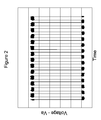
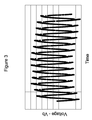
- Figures 2 and 3 are graphs of the clock output signal voltage at the input and termination of a high resistance wire transmission line composed of a pair of conductors each having a resistance of, for example, 130 K ⁇ /m, and a long run of, for example, about 10m.
- the clock output signal is provided on the transmission line 55 at the output of the clock circuit 40, and has a voltage of Va that varies over time.
- the clock output signal Va shown in the graph of Figure 2 , has a fundamental frequency corresponding to the capacitance of the fuel probe 30. Exterior to the fuel tank 15, the transmission line 55 terminates at the avionics interface circuit 60.
- the clock output signal Vb at the termination of transmission line 55 likewise varies over time.
- the clock output signal Vb is a distorted version of the clock output signal Va because of transmission line losses that occur over the length of the transmission line 55. More particularly, the distortion may be caused by attenuation of the higher frequency content of the clock output signal Vb.
- the avionics interface circuit 60 may therefore be configured to recover the fundamental frequency component from Vb for determining the level of the fuel 25 and providing this information to the avionics 65.
- FIG 4 is a schematic diagram of one example of a clock circuit 80 that may be used in the clock circuit 40 of Figure 1 .
- the clock circuit 80 uses an odd number of series NAND gates 85, 90, and 95.
- the signal at output V out of NAND gate 95 is fed back to the input of NAND gate 85 through a pair of resistors 100 and 105.
- the fuel probe 30 is connected as a variable capacitor between the output of NAND gate 90 and the junction between resistors 100 and 105.
- This configuration results in an oscillator having a pulsed output at V out with a frequency that corresponds to the capacitance of the fuel probe 30.
- the values of resistors 100 and 105 are used to tune the relationship between the variable capacitance of the fuel probe 30 and the frequency of the clock output signal at V out .
- the clock output signal V out may be buffered before it is provided as the clock output voltage Va on transmission line 55 of Figure 1 .
- FIG 5 is a schematic diagram of another example of a clock circuit 110 that may be used in the clock circuit 40 of Figure 1 .
- the clock circuit 110 may be implemented on a single printed circuit board 115, which can be mounted directly to the fuel probe 30. Other means of maintaining the clock circuit 110 in close proximity to the fuel probe 30 may be used, as noted above.
- the clock circuit 110 is principally based around a clock generator 120.
- the clock generator 120 may be a 555-style low-power CMOS timer circuit, or another integrated timer or clock circuit.
- Power for the clock generator 120 is provided from power line 75 to terminal 125 of the printed circuit board 115.
- Power line 75 may include high resistance wire to facilitate long runs though electromagnetic environments where metallic wiring is not desired. High resistance wire may be used given the low power consumption of the CMOS clock generator 120 used in this example.
- a voltage regulator diode 130 such as a Zener diode, and a capacitor 135 are connected in parallel with one another to regulate the voltage received at terminal 125.
- the regulated voltage is provided to several inputs of the clock generator 120. In Figure 5 , the regulated voltage is provided to the power input V CC . Further, it is provided to the RESET terminal to keep the reset signal at an inactive state. However, the RESET terminal may alternatively be connected to a reset timer, or the like, to reset the clock generator 120 if an operational anomaly occurs.
- the clock circuit 110 may be designed to operate in an astable mode while the reset signal is in an inactive state. For continuous operation, the DISCHARGE terminal and TRIGGER terminal may be connected to one another through resistor 150.
- the clock output signal is at the OUTPUT terminal of the clock generator 120 which is in electrical communication with terminal 140 of the printed circuit board 115.
- the clock output signal at terminal 140 is provided to the avionics interface circuit 60 along transmission line 55.
- the transmission line 55 may include high resistance wire.
- the signals at the THRESHOLD terminal and the DISCHARGE terminal are the principal signals used to generate the clock output signal at the OUTPUT terminal.
- the THRESHOLD terminal is connected to receive the voltage at the capacitor represented by the fuel probe 30 which is charged using resistors 145 and 150, where resistor 145 is connected to V CC . Further, the THRESHOLD terminal and the DISCHARGE terminal are connected with one another through resistor 150. Resistor 150 is connected to a terminal 155 of the printed circuit board 115, which is connected to a first terminal of the variable capacitor of the fuel probe 30. The second terminal of the variable capacitor of fuel probe 30 is received at terminal 155, which is connected to ground.
- Resistors 145 and 150 operate to tune the clock circuit 110 and variable capacitance of fuel probe 30 so the frequency of the clock output signal remains within a specified range.
- the frequency of the clock output signal is in a range between about 600 Hz and about 2kHz.
- Figure 6 is an example of one relationship between the fuel level and the frequency of the clock output signal using the clock generator design of Figure 5 .
- the frequency of the clock output signal is inversely proportional to the capacitance of the fuel probe 30.
- exemplary values for the components connected to the CMOS 555 timer IC of Figure 5 may be: R 145 ⁇ 340 ⁇ K ⁇ ; R 150 ⁇ 562 ⁇ K ⁇ ; and C PROBE ⁇ 100 ⁇ pF to 1 ⁇ nF .
- this formula may define the range of the frequency of the clock output signal at the OUTPUT of clock generator 120.
- Figure 7 shows another example of a system 10, such as an aircraft system, in which the level of fuel in the fuel tank is measured using an in-tank measuring system.
- the in-tank measuring system communicates with an electrical circuit exterior to the fuel tank 15 over an optical path.
- the clock circuit 40 provides the clock output signal to an optical interface 160.
- the optical interface 160 converts the clock output signal to an optical clock signal having a frequency corresponding to the frequency of the clock output signal of the clock circuit 40.
- the optical clock signal is transmitted along an optical path 165, such as an optical path having an optical fiber or other means of defining an optical path.
- the optical clock signal is transmitted along the optical path 165 to the avionics interface circuit 60, where it is converted back to an electrical clock output signal for use by the avionics 65.
- Energy received along the optical path 165 from the avionics interface circuit 60, or other optical source, may be converted to electrical energy by the optical interface 160 and used to provide power to operate one or both the optical interface 160 and clock circuit 40.
- a separate power supply 170 may be connected to an analog transmission line 173.
- the analog transmission line 173 may include high resistance wire.
- the optical interface 160 may be positioned in close proximity to the clock circuit 40 to reduce the length of the run of electrical wires therebetween.
- the optical interface 160 is mounted directly to the clock circuit 40.
- the optical interface 160 may be mounted to an interior wall of fuel tank 15 in close proximity to the clock circuit 40.
- the optical interface 160 may be mounted to the fuel probe 30 or the support members 35. Any electrical wires extending between the clock circuit 40 and the optical interface 160 may include high resistance wire.
- Figure 8 shows one implementation of the system in Figure 7 , including the optical interface 160.
- the optical clock signal from the optical interface 160 is transmitted to the avionics interface circuit 60 in a first direction over optical path 165.
- Optical energy for powering the optical interface 160 and clock circuit 40 is received in a second direction over optical path 165.
- the optical clock signals and the optical energy are therefore transmitted in opposite directions.
- the optical interface 160 separates the signals from one another for separate processing.
- the signals are separated by an optical splitter/combiner configured to transmit and receive signals over the optical path 165.
- a mirror/prism 175 is used for this purpose.
- power to operate the clock circuit 40 and optical interface 160 is provided over optical path 165. More particularly, the optical energy received over the optical path 165 is directed to the mirror/prism 175. The mirror/prism 175 directs the optical energy to a photodiode 185 along an optical path 180.
- the optical energy provided to the photodiode 185 may have the same wavelength or a different wavelength than the optical clock signal.
- the photodiode 185 converts the optical energy received along optical path 180 into electrical energy. The electrical energy is used to power the clock circuit 40.
- a capacitor 190 may be placed in parallel with the photodiode 185 to reduce power transients.
- other components such as a Zener diode, may regulate the output voltage of the photodiode 185.
- the electrical power at line 187 also provides power to an optical emitter 195, such as an LED/laser.
- the light emitted from the optical emitter 195 is modulated by the clock output signal received from the clock circuit 40.
- the clock output signal at line 200 is an electrical signal, which is converted by optical emitter 195 to an optical clock signal having a frequency corresponding to the frequency of the clock output signal of the clock circuit 40.
- the optical emitter 195 directs the optical clock signal to the mirror/prism 175 along optical path 205. In turn, the mirror/prism 175 directs the optical clock signal to optical path 165 for transmission to the avionics interface circuit 60.
- FIG. 9 shows another example of system 10 in which the level of fuel in a fuel tank is measured.
- the in-tank measuring system uses a wireless transmitter 215 that communicates with a wireless receiver 225 over a wireless path 240.
- the wireless transmitter 215 is disposed in close proximity to the clock circuit 40 and fuel probe 30, while the wireless receiver 225 is disposed at an inner boundary of the fuel tank 15.
- the clock output signal of clock circuit 40 is provided to the input of the wireless transmitter 215, which uses the clock output signal to modulate a wireless signal.
- the modulated wireless signal is transmitted by antenna 217 over wireless path 240 to a corresponding antenna 219 of the wireless receiver 225, which is in communication with a receiver interface 229 of the avionics interface circuit 60.
- the wireless signal includes at least one signal parameter corresponding to the frequency of the clock output signal.
- An energy unit 237 is disposed in interior space 20 and provides power to the clock circuit 40 and wireless transmitter 215.
- the energy unit 237 may generate power in several ways.
- a wireless transmitter 230 may be disposed at an inner boundary of the fuel tank 15. Power may be provided to the wireless transmitter 230 from a transmitter interface 235 of the avionics interface circuit 60. The received power is transmitted from the wireless transmitter 230 to a corresponding wireless receiver 239 over a wireless path 243 between antennas 247 and 253.
- the wireless receiver 239 may be disposed in close proximity to the energy unit 237, the wireless transmitter 215, clock circuit 40, and/or fuel probe 30.
- the wireless receiver 239 is in communication with the energy unit 237, which, in turn, uses that energy to operate the clock circuit 40 and wireless transmitter 215.
- the wireless transmitter 230 may be omitted, and the energy unit 237 may be configured to convert vibrational energy into electrical energy to operate the clock circuit 40 and wireless transmitter 215.
- the energy unit 237 may use both RF energy and vibrational energy to supply power to the clock circuit 40 and wireless transmitter 215.
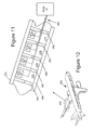
- Figure 10 shows an aircraft 250 having wing fuel tanks in section 255.
- Section 255 may comprise stringers and ribs that support the outer skin of the wing.
- FIG 11 is a cutaway view of section 255.
- section 255 comprises a plurality of ribs 260 disposed between a front spar 265 and rear spar 270.
- the ribs 260, front spar 265, and rear spar 270 define a plurality of fuel tank sections 275.
- Each fuel tank section 275 may have one or more respective in-tank measuring systems 280.
- each in-tank measuring system 280 may include a respective capacitive fuel probe and clock circuit, where the respective clock circuit is configured for mounting at a position in close proximity to the respective fuel probe.
- Figures 1 , 5 , and 7-9 represent systems that may be used for the in-tank measuring systems 280.
- the clock outputs of the in-tank measuring systems 280 may be provided on respective transmission lines 285 to an avionics interface circuit 60 of, for example, the Fuel Quantity Indicating System 57.
- the transmission lines 285 may include high resistance wire, optical fibers, optical waveguides, radio frequency waveguides, or a combination of such elements. When the in-tank measuring systems 280 are constructed for wireless operation, the transmission lines 285 may be omitted.
- an apparatus for measuring a level of fuel in a fuel tank comprising:
- the communication path includes high resistance wire.
- the communication path includes an optical path.
- the communication path includes a wireless path enabled by RF energy.
- the in-tank measuring system comprises:
- the apparatus further comprises a power line extending between a location exterior to the fuel tank and the clock circuit, wherein the power line provides power to the clock circuit.
- the power line includes high resistance wire
- the clock circuit includes a low power CMOS timer circuit.
- the capacitive fuel probe is configured for mounting within a fuel tank of an aircraft.
- the clock circuit is configured for mounting in a position substantially adjacent to the capacitive fuel probe.
- the clock circuit is configured for mounting to a support of the capacitive fuel probe.
- the apparatus further comprises a wireless transmitter disposed in close proximity to the clock circuit, wherein the wireless transmitter is configured to convey a wireless signal to a wireless receiver disposed at an inner boundary of the fuel tank, wherein the conveyed signal has at least one signal parameter corresponding to the frequency of the clock output signal.
- an apparatus for measuring a level of fuel in a fuel tank comprising:
- the optical interface comprises a photodiode configured to receive optical energy over the optical path, wherein the photodiode is further configured to convert the optical energy to electrical energy that is used to power the clock circuit.
- the optical interface comprises an optical emitter configured to provide the optical clock signal for transmission over the optical path.
- the optical interface comprises:
- the apparatus further comprises:
- the clock circuit is configured for mounting at a position adjacent the capacitive fuel probe.
- the optical interface is configured for mounting at a position adjacent the clock circuit.
- a system for measuring a level of fuel in a plurality of fuel tank sections of an aircraft comprising:
- the plurality of in-tank measuring systems comprise:
- the plurality of fuel tank sections are disposed in at least one wing of the aircraft.
- the one or more electrical circuits exterior to the plurality of fuel tank sections comprise avionics for the aircraft.
- the one or more communication paths are formed from high resistance wire.
- the one or more communication paths comprise optical paths.
- the one or more communication paths comprise wireless paths enabled by RF energy.
Landscapes
- Physics & Mathematics (AREA)
- Engineering & Computer Science (AREA)
- Power Engineering (AREA)
- Electromagnetism (AREA)
- Thermal Sciences (AREA)
- Fluid Mechanics (AREA)
- General Physics & Mathematics (AREA)
- Arrangements For Transmission Of Measured Signals (AREA)
- Measurement Of Levels Of Liquids Or Fluent Solid Materials (AREA)
Applications Claiming Priority (1)
| Application Number | Priority Date | Filing Date | Title |
|---|---|---|---|
| US13/892,761 US10429228B2 (en) | 2013-05-13 | 2013-05-13 | Fuel level measurement using in-tank measuring system |
Publications (2)
| Publication Number | Publication Date |
|---|---|
| EP2808659A1 true EP2808659A1 (de) | 2014-12-03 |
| EP2808659B1 EP2808659B1 (de) | 2020-10-28 |
Family
ID=50685841
Family Applications (1)
| Application Number | Title | Priority Date | Filing Date |
|---|---|---|---|
| EP14168193.2A Active EP2808659B1 (de) | 2013-05-13 | 2014-05-13 | Kraftstofffüllstandsmessung mit Messsystem im Tank |
Country Status (2)
| Country | Link |
|---|---|
| US (1) | US10429228B2 (de) |
| EP (1) | EP2808659B1 (de) |
Families Citing this family (13)
| Publication number | Priority date | Publication date | Assignee | Title |
|---|---|---|---|---|
| US9671279B2 (en) * | 2012-12-19 | 2017-06-06 | Zodiac Aerotechnics | Optically-powered sensor systems principally for deployment on-board aircraft and in which optical data is transmitted as available electrical energy permits |
| FR3037649B1 (fr) * | 2015-06-16 | 2017-07-07 | Coutier Moulage Gen Ind | Dispositif et procede de mesure de hauteur de liquide dans un conteneur |
| TWI553300B (zh) * | 2015-12-01 | 2016-10-11 | 財團法人工業技術研究院 | 液面感測裝置 |
| US10101191B2 (en) | 2016-01-12 | 2018-10-16 | Tank Vision, Inc. | Fuel tank level monitoring system |
| US10107774B2 (en) | 2016-03-18 | 2018-10-23 | Simonds Precision Products, Inc. | Optically interfaced fuel characteristic sensor |
| US10048186B2 (en) * | 2016-03-18 | 2018-08-14 | Simmonds Precision Products, Inc. | Optically interfaced fluid density sensor |
| US10451446B2 (en) * | 2018-01-19 | 2019-10-22 | Rosemount Aerospace Inc. | System for interfacing with an optically-powered sensor |
| US11325720B2 (en) * | 2019-03-19 | 2022-05-10 | The Boeing Company | Electric power and data communications within a fuel tank and across a wall of the fuel tank using resistive non-metallic wire |
| US11305884B2 (en) * | 2019-03-19 | 2022-04-19 | The Boeing Company | Electric power and data communications within a fuel tank and across a wall of the fuel tank using resistive non-metallic wire and an optical hybrid fuel height sensor |
| RU2759208C1 (ru) * | 2020-08-03 | 2021-11-10 | Федеральное государственное бюджетное образовательное учреждение высшего образования "Уфимский государственный нефтяной технический университет" | Способ измерения уровня жидкости и массы в топливных баках и танках при качке и наклонах и устройство для его осуществления |
| US12270695B2 (en) | 2020-10-19 | 2025-04-08 | Parker-Hannifin Corporation | Capacitive fuel gaging system with resistive elements |
| US12181324B2 (en) | 2021-05-17 | 2024-12-31 | G & G Group, Llc | Vehicle liquid level tank sensing system and related methods |
| US11852518B2 (en) | 2021-05-19 | 2023-12-26 | The Boeing Company | Resistive wire wiring shield to prevent electromagnetic interference |
Citations (4)
| Publication number | Priority date | Publication date | Assignee | Title |
|---|---|---|---|---|
| US5602333A (en) * | 1994-06-17 | 1997-02-11 | Smiths Industries | Apparatus for measuring the level of a liquid in a tank |
| US6356809B1 (en) * | 1999-06-11 | 2002-03-12 | Cbi Systems Corporation | Electro-statically shielded processing module |
| US20100154534A1 (en) * | 2008-12-23 | 2010-06-24 | Little Giant Pump Company | Method and apparatus for capacitive sensing the top level of a material in a vessel |
| US20100251816A1 (en) * | 2009-04-03 | 2010-10-07 | Eaton Corporation | Fuel gauging system utilizing a digital fuel gauging probe |
Family Cites Families (40)
| Publication number | Priority date | Publication date | Assignee | Title |
|---|---|---|---|---|
| US2354964A (en) | 1939-05-03 | 1944-08-01 | Wheelco Instr Company | Liquid level sensitive apparatus |
| US2621517A (en) | 1948-12-14 | 1952-12-16 | Liquidometer Corp | Resonance type capacitance responsive gauge |
| US3027751A (en) * | 1957-09-20 | 1962-04-03 | Canadian Ind | Apparatus for determining detonation or burning velocities of materials |
| US2997577A (en) * | 1960-01-04 | 1961-08-22 | Bell Telephone Labor Inc | Synchronous carrier production |
| US3140608A (en) | 1960-12-16 | 1964-07-14 | Brooks Equipment Corp | Liquid level gauge |
| DE2645716C2 (de) | 1976-10-09 | 1982-11-04 | Vdo Adolf Schindling Ag, 6000 Frankfurt | Einrichtung zum kontinuierlichen Messen des Flüssigkeitsstandes in einem Behälter |
| US4080563A (en) | 1976-11-08 | 1978-03-21 | Dickey-John Corporation | Haylage/silage moisture tester |
| GB1601338A (en) | 1977-03-14 | 1981-10-28 | Huddart R | Measuring apparatus using parameter dependant capacitance |
| US4258422A (en) | 1979-05-04 | 1981-03-24 | Honeywell Inc. | Liquid gaging system |
| US4377961A (en) * | 1979-09-10 | 1983-03-29 | Bode Harald E W | Fundamental frequency extracting system |
| US4289028A (en) | 1979-12-27 | 1981-09-15 | Simmonds Precision Products, Inc. | Fuel quantity gauge |
| IT1131315B (it) * | 1980-06-13 | 1986-06-18 | Logic Spa | Sistema di rilevamento e segnalazione della quantita' di carburante contenuto in un serbatoio di veicoli,particolarmente di veicoli aerei |
| JPS57168169A (en) * | 1981-04-10 | 1982-10-16 | Nissan Motor Co Ltd | Electrostatic capacitance detector |
| WO1984001428A1 (en) | 1982-09-30 | 1984-04-12 | Boeing Co | Fuel gaging system |
| US4515015A (en) * | 1983-02-16 | 1985-05-07 | Magnetrol International, Incorporated | Capacitance level sensor for use with viscous, electrically conductive materials |
| US4591946A (en) * | 1985-04-30 | 1986-05-27 | Southwest Pump Company | Capacitance probe for use in a measuring system for location of a liquid level interface |
| US4656353A (en) * | 1986-01-21 | 1987-04-07 | The Babcock & Wilcox Company | Variable pulse rate led electronics for a fiber optic vortex shedding flowmeter |
| JPH0724277B2 (ja) * | 1990-02-27 | 1995-03-15 | 三洋電機株式会社 | 半導体装置 |
| US5101190A (en) * | 1990-03-28 | 1992-03-31 | W. L. Gore & Associates, Inc. | Non-metal high resistance electric cable |
| FR2695203B1 (fr) * | 1992-08-28 | 1994-11-04 | Intertechnique Sa | Détecteur de liquide à thermistance. |
| US5723870A (en) * | 1993-05-28 | 1998-03-03 | Simmonds Precision Products Inc. | Fluid gauging apparatus using magnetostrictive sensor and stick gauge |
| GB9411525D0 (en) * | 1994-06-09 | 1994-08-03 | Smiths Industries Plc | Fuel gauging systems |
| KR100429878B1 (ko) * | 2001-09-10 | 2004-05-03 | 삼성전자주식회사 | 메모리 모듈과 그에 사용되는 인쇄회로기판 |
| JP4327504B2 (ja) * | 2003-05-29 | 2009-09-09 | Necエレクトロニクス株式会社 | トランスミッタ回路、伝送回路及び駆動装置 |
| KR100945852B1 (ko) * | 2003-09-30 | 2010-03-08 | 마이크로 모우션, 인코포레이티드 | 2선 버스 장치 |
| US7132667B2 (en) * | 2004-02-11 | 2006-11-07 | General Electric Company | Method and apparatus for improved data acquisition using a solid state digital X-ray detector |
| US7214189B2 (en) * | 2004-09-02 | 2007-05-08 | Proteus Biomedical, Inc. | Methods and apparatus for tissue activation and monitoring |
| JP4391976B2 (ja) * | 2005-09-16 | 2009-12-24 | 富士通株式会社 | クロック分配回路 |
| FR2892509B1 (fr) * | 2005-10-26 | 2007-12-21 | Inergy Automotive Systems Res | Jauge capacitive pour reservoir a carburant |
| EP1811274A1 (de) * | 2006-01-19 | 2007-07-25 | Whirlpool Corporation | Wasserstandmesssystem |
| US8222079B2 (en) * | 2007-09-28 | 2012-07-17 | International Business Machines Corporation | Semiconductor device and method of making semiconductor device |
| CA2629960C (en) * | 2008-04-28 | 2009-12-08 | Westport Power Inc. | Apparatus and method for improving the accuracy of measurements taken with a capacitance-type sensor |
| US20100045473A1 (en) * | 2008-08-20 | 2010-02-25 | The Southern Company | Non-metallic alert systems |
| US20100109859A1 (en) * | 2008-10-31 | 2010-05-06 | Lakosky Allen J | Hazard Flasher System for Personal Motor Vehicles |
| CN102460137A (zh) * | 2009-06-08 | 2012-05-16 | S.E.A.医疗系统公司 | 用于使用导纳谱法鉴定医用流体中的化合物的系统和方法 |
| US8816497B2 (en) * | 2010-01-08 | 2014-08-26 | Transphorm Inc. | Electronic devices and components for high efficiency power circuits |
| KR101678916B1 (ko) * | 2010-07-12 | 2016-12-07 | 삼성전자주식회사 | 고속 데이터 버스 시스템 및 이를 이용한 이미지 센서 |
| US9299471B1 (en) * | 2010-09-23 | 2016-03-29 | The Boeing Company | Highly resistive wiring for inherent safety from electromagnetic threats |
| US8884769B2 (en) * | 2011-04-05 | 2014-11-11 | Guy R. Novak | Dimensionally-sensitive moisture sensor and an alarm system for an absorbent article |
| AU2014232293A1 (en) * | 2013-03-15 | 2015-07-30 | C.R. Bard, Inc. | Urine monitoring systems and methods |
-
2013
- 2013-05-13 US US13/892,761 patent/US10429228B2/en active Active
-
2014
- 2014-05-13 EP EP14168193.2A patent/EP2808659B1/de active Active
Patent Citations (4)
| Publication number | Priority date | Publication date | Assignee | Title |
|---|---|---|---|---|
| US5602333A (en) * | 1994-06-17 | 1997-02-11 | Smiths Industries | Apparatus for measuring the level of a liquid in a tank |
| US6356809B1 (en) * | 1999-06-11 | 2002-03-12 | Cbi Systems Corporation | Electro-statically shielded processing module |
| US20100154534A1 (en) * | 2008-12-23 | 2010-06-24 | Little Giant Pump Company | Method and apparatus for capacitive sensing the top level of a material in a vessel |
| US20100251816A1 (en) * | 2009-04-03 | 2010-10-07 | Eaton Corporation | Fuel gauging system utilizing a digital fuel gauging probe |
Also Published As
| Publication number | Publication date |
|---|---|
| EP2808659B1 (de) | 2020-10-28 |
| US20140331763A1 (en) | 2014-11-13 |
| US10429228B2 (en) | 2019-10-01 |
Similar Documents
| Publication | Publication Date | Title |
|---|---|---|
| US10429228B2 (en) | Fuel level measurement using in-tank measuring system | |
| US9658095B2 (en) | Capacitive fill level sensor | |
| US8497799B2 (en) | FMCW-type radar level gauge | |
| EP3287753B1 (de) | Systeme und verfahren zur bestimmung einer kraftstoffffüllstandsmessung eines kraftstofftanks mit optischen sensoren | |
| US9671488B2 (en) | Radar level gauge with signal division | |
| US20200298991A1 (en) | Electric power and data communications within a fuel tank and across a wall of the fuel tank using resistive non-metallic wire and a sealed active connector | |
| US20120137767A1 (en) | Time domain reflectometry device and method | |
| EP3712573B1 (de) | Elektrische energie und datenkommunikation innerhalb eines kraftstofftanks und über eine wand des kraftstofftanks unter verwendung eines resistiven nichtmetallischen drahtes | |
| GB2077924A (en) | Measuring fuel in tank | |
| US9964426B2 (en) | Process and apparatus for the measurement | |
| US9910025B2 (en) | Integrated active fuel characteristic sensor | |
| US5339022A (en) | Capacitive cable length indicator | |
| US10935634B2 (en) | In situ verification of guided wave radar device | |
| US20150053004A1 (en) | Digital densitometer and fuel gauging system | |
| EP3631383B1 (de) | Feldvorrichtung | |
| US20040140814A1 (en) | Level meter | |
| US7227495B2 (en) | Radar fill-level sensing device | |
| EP3640653A1 (de) | Beobachtungsschaltung zum beobachten einer eingangsimpedanz an einem hochfrequenzverbinder eines mobilvorrichtungsendgeräts und mobilvorrichtungsendgerät mit solch einer beobachtungsschaltung und fahrzeug mit dem mobilvorrichtungsendgerät | |
| US20230089470A1 (en) | Compensating for drift in a switch gear voltage sensor | |
| BR102012027858A2 (pt) | Sonda para usar em um conjunto de sensores e conjunto de sensores | |
| JP4986134B2 (ja) | 赤外線タッチスイッチ | |
| US10018495B2 (en) | Radar-based fill-level measuring device having a synthesizer circuit | |
| EP3080637B1 (de) | Fehlerreduktion bei strahlungsbasierten temperaturmesssystemen | |
| Gao et al. | EMI analysis and improvement of fuel quantity indication system on board | |
| EP1832869A1 (de) | Sensorvorrichtung und Verfahren zu deren Betrieb |
Legal Events
| Date | Code | Title | Description |
|---|---|---|---|
| PUAI | Public reference made under article 153(3) epc to a published international application that has entered the european phase |
Free format text: ORIGINAL CODE: 0009012 |
|
| 17P | Request for examination filed |
Effective date: 20140513 |
|
| AK | Designated contracting states |
Kind code of ref document: A1 Designated state(s): AL AT BE BG CH CY CZ DE DK EE ES FI FR GB GR HR HU IE IS IT LI LT LU LV MC MK MT NL NO PL PT RO RS SE SI SK SM TR |
|
| AX | Request for extension of the european patent |
Extension state: BA ME |
|
| STAA | Information on the status of an ep patent application or granted ep patent |
Free format text: STATUS: EXAMINATION IS IN PROGRESS |
|
| 17Q | First examination report despatched |
Effective date: 20190919 |
|
| GRAP | Despatch of communication of intention to grant a patent |
Free format text: ORIGINAL CODE: EPIDOSNIGR1 |
|
| STAA | Information on the status of an ep patent application or granted ep patent |
Free format text: STATUS: GRANT OF PATENT IS INTENDED |
|
| INTG | Intention to grant announced |
Effective date: 20200422 |
|
| GRAS | Grant fee paid |
Free format text: ORIGINAL CODE: EPIDOSNIGR3 |
|
| GRAJ | Information related to disapproval of communication of intention to grant by the applicant or resumption of examination proceedings by the epo deleted |
Free format text: ORIGINAL CODE: EPIDOSDIGR1 |
|
| GRAL | Information related to payment of fee for publishing/printing deleted |
Free format text: ORIGINAL CODE: EPIDOSDIGR3 |
|
| STAA | Information on the status of an ep patent application or granted ep patent |
Free format text: STATUS: EXAMINATION IS IN PROGRESS |
|
| STAA | Information on the status of an ep patent application or granted ep patent |
Free format text: STATUS: GRANT OF PATENT IS INTENDED |
|
| GRAA | (expected) grant |
Free format text: ORIGINAL CODE: 0009210 |
|
| STAA | Information on the status of an ep patent application or granted ep patent |
Free format text: STATUS: THE PATENT HAS BEEN GRANTED |
|
| INTG | Intention to grant announced |
Effective date: 20200422 |
|
| AK | Designated contracting states |
Kind code of ref document: B1 Designated state(s): AL AT BE BG CH CY CZ DE DK EE ES FI FR GB GR HR HU IE IS IT LI LT LU LV MC MK MT NL NO PL PT RO RS SE SI SK SM TR |
|
| REG | Reference to a national code |
Ref country code: GB Ref legal event code: FG4D |
|
| REG | Reference to a national code |
Ref country code: CH Ref legal event code: EP |
|
| REG | Reference to a national code |
Ref country code: AT Ref legal event code: REF Ref document number: 1328665 Country of ref document: AT Kind code of ref document: T Effective date: 20201115 |
|
| REG | Reference to a national code |
Ref country code: DE Ref legal event code: R096 Ref document number: 602014071629 Country of ref document: DE |
|
| REG | Reference to a national code |
Ref country code: IE Ref legal event code: FG4D |
|
| REG | Reference to a national code |
Ref country code: AT Ref legal event code: MK05 Ref document number: 1328665 Country of ref document: AT Kind code of ref document: T Effective date: 20201028 |
|
| REG | Reference to a national code |
Ref country code: NL Ref legal event code: MP Effective date: 20201028 |
|
| PG25 | Lapsed in a contracting state [announced via postgrant information from national office to epo] |
Ref country code: NL Free format text: LAPSE BECAUSE OF FAILURE TO SUBMIT A TRANSLATION OF THE DESCRIPTION OR TO PAY THE FEE WITHIN THE PRESCRIBED TIME-LIMIT Effective date: 20201028 Ref country code: NO Free format text: LAPSE BECAUSE OF FAILURE TO SUBMIT A TRANSLATION OF THE DESCRIPTION OR TO PAY THE FEE WITHIN THE PRESCRIBED TIME-LIMIT Effective date: 20210128 Ref country code: PT Free format text: LAPSE BECAUSE OF FAILURE TO SUBMIT A TRANSLATION OF THE DESCRIPTION OR TO PAY THE FEE WITHIN THE PRESCRIBED TIME-LIMIT Effective date: 20210301 Ref country code: RS Free format text: LAPSE BECAUSE OF FAILURE TO SUBMIT A TRANSLATION OF THE DESCRIPTION OR TO PAY THE FEE WITHIN THE PRESCRIBED TIME-LIMIT Effective date: 20201028 Ref country code: FI Free format text: LAPSE BECAUSE OF FAILURE TO SUBMIT A TRANSLATION OF THE DESCRIPTION OR TO PAY THE FEE WITHIN THE PRESCRIBED TIME-LIMIT Effective date: 20201028 Ref country code: GR Free format text: LAPSE BECAUSE OF FAILURE TO SUBMIT A TRANSLATION OF THE DESCRIPTION OR TO PAY THE FEE WITHIN THE PRESCRIBED TIME-LIMIT Effective date: 20210129 |
|
| REG | Reference to a national code |
Ref country code: LT Ref legal event code: MG4D |
|
| PG25 | Lapsed in a contracting state [announced via postgrant information from national office to epo] |
Ref country code: BG Free format text: LAPSE BECAUSE OF FAILURE TO SUBMIT A TRANSLATION OF THE DESCRIPTION OR TO PAY THE FEE WITHIN THE PRESCRIBED TIME-LIMIT Effective date: 20210128 Ref country code: ES Free format text: LAPSE BECAUSE OF FAILURE TO SUBMIT A TRANSLATION OF THE DESCRIPTION OR TO PAY THE FEE WITHIN THE PRESCRIBED TIME-LIMIT Effective date: 20201028 Ref country code: AT Free format text: LAPSE BECAUSE OF FAILURE TO SUBMIT A TRANSLATION OF THE DESCRIPTION OR TO PAY THE FEE WITHIN THE PRESCRIBED TIME-LIMIT Effective date: 20201028 Ref country code: IS Free format text: LAPSE BECAUSE OF FAILURE TO SUBMIT A TRANSLATION OF THE DESCRIPTION OR TO PAY THE FEE WITHIN THE PRESCRIBED TIME-LIMIT Effective date: 20210228 Ref country code: SE Free format text: LAPSE BECAUSE OF FAILURE TO SUBMIT A TRANSLATION OF THE DESCRIPTION OR TO PAY THE FEE WITHIN THE PRESCRIBED TIME-LIMIT Effective date: 20201028 Ref country code: LV Free format text: LAPSE BECAUSE OF FAILURE TO SUBMIT A TRANSLATION OF THE DESCRIPTION OR TO PAY THE FEE WITHIN THE PRESCRIBED TIME-LIMIT Effective date: 20201028 Ref country code: PL Free format text: LAPSE BECAUSE OF FAILURE TO SUBMIT A TRANSLATION OF THE DESCRIPTION OR TO PAY THE FEE WITHIN THE PRESCRIBED TIME-LIMIT Effective date: 20201028 |
|
| PG25 | Lapsed in a contracting state [announced via postgrant information from national office to epo] |
Ref country code: HR Free format text: LAPSE BECAUSE OF FAILURE TO SUBMIT A TRANSLATION OF THE DESCRIPTION OR TO PAY THE FEE WITHIN THE PRESCRIBED TIME-LIMIT Effective date: 20201028 |
|
| REG | Reference to a national code |
Ref country code: DE Ref legal event code: R097 Ref document number: 602014071629 Country of ref document: DE |
|
| PG25 | Lapsed in a contracting state [announced via postgrant information from national office to epo] |
Ref country code: RO Free format text: LAPSE BECAUSE OF FAILURE TO SUBMIT A TRANSLATION OF THE DESCRIPTION OR TO PAY THE FEE WITHIN THE PRESCRIBED TIME-LIMIT Effective date: 20201028 Ref country code: SK Free format text: LAPSE BECAUSE OF FAILURE TO SUBMIT A TRANSLATION OF THE DESCRIPTION OR TO PAY THE FEE WITHIN THE PRESCRIBED TIME-LIMIT Effective date: 20201028 Ref country code: LT Free format text: LAPSE BECAUSE OF FAILURE TO SUBMIT A TRANSLATION OF THE DESCRIPTION OR TO PAY THE FEE WITHIN THE PRESCRIBED TIME-LIMIT Effective date: 20201028 Ref country code: CZ Free format text: LAPSE BECAUSE OF FAILURE TO SUBMIT A TRANSLATION OF THE DESCRIPTION OR TO PAY THE FEE WITHIN THE PRESCRIBED TIME-LIMIT Effective date: 20201028 Ref country code: EE Free format text: LAPSE BECAUSE OF FAILURE TO SUBMIT A TRANSLATION OF THE DESCRIPTION OR TO PAY THE FEE WITHIN THE PRESCRIBED TIME-LIMIT Effective date: 20201028 Ref country code: SM Free format text: LAPSE BECAUSE OF FAILURE TO SUBMIT A TRANSLATION OF THE DESCRIPTION OR TO PAY THE FEE WITHIN THE PRESCRIBED TIME-LIMIT Effective date: 20201028 |
|
| PG25 | Lapsed in a contracting state [announced via postgrant information from national office to epo] |
Ref country code: DK Free format text: LAPSE BECAUSE OF FAILURE TO SUBMIT A TRANSLATION OF THE DESCRIPTION OR TO PAY THE FEE WITHIN THE PRESCRIBED TIME-LIMIT Effective date: 20201028 |
|
| PLBE | No opposition filed within time limit |
Free format text: ORIGINAL CODE: 0009261 |
|
| STAA | Information on the status of an ep patent application or granted ep patent |
Free format text: STATUS: NO OPPOSITION FILED WITHIN TIME LIMIT |
|
| 26N | No opposition filed |
Effective date: 20210729 |
|
| PG25 | Lapsed in a contracting state [announced via postgrant information from national office to epo] |
Ref country code: IT Free format text: LAPSE BECAUSE OF FAILURE TO SUBMIT A TRANSLATION OF THE DESCRIPTION OR TO PAY THE FEE WITHIN THE PRESCRIBED TIME-LIMIT Effective date: 20201028 Ref country code: AL Free format text: LAPSE BECAUSE OF FAILURE TO SUBMIT A TRANSLATION OF THE DESCRIPTION OR TO PAY THE FEE WITHIN THE PRESCRIBED TIME-LIMIT Effective date: 20201028 |
|
| PG25 | Lapsed in a contracting state [announced via postgrant information from national office to epo] |
Ref country code: SI Free format text: LAPSE BECAUSE OF FAILURE TO SUBMIT A TRANSLATION OF THE DESCRIPTION OR TO PAY THE FEE WITHIN THE PRESCRIBED TIME-LIMIT Effective date: 20201028 |
|
| REG | Reference to a national code |
Ref country code: CH Ref legal event code: PL |
|
| PG25 | Lapsed in a contracting state [announced via postgrant information from national office to epo] |
Ref country code: CH Free format text: LAPSE BECAUSE OF NON-PAYMENT OF DUE FEES Effective date: 20210531 Ref country code: LI Free format text: LAPSE BECAUSE OF NON-PAYMENT OF DUE FEES Effective date: 20210531 Ref country code: LU Free format text: LAPSE BECAUSE OF NON-PAYMENT OF DUE FEES Effective date: 20210513 Ref country code: MC Free format text: LAPSE BECAUSE OF FAILURE TO SUBMIT A TRANSLATION OF THE DESCRIPTION OR TO PAY THE FEE WITHIN THE PRESCRIBED TIME-LIMIT Effective date: 20201028 |
|
| REG | Reference to a national code |
Ref country code: BE Ref legal event code: MM Effective date: 20210531 |
|
| PG25 | Lapsed in a contracting state [announced via postgrant information from national office to epo] |
Ref country code: IE Free format text: LAPSE BECAUSE OF NON-PAYMENT OF DUE FEES Effective date: 20210513 |
|
| PG25 | Lapsed in a contracting state [announced via postgrant information from national office to epo] |
Ref country code: IS Free format text: LAPSE BECAUSE OF FAILURE TO SUBMIT A TRANSLATION OF THE DESCRIPTION OR TO PAY THE FEE WITHIN THE PRESCRIBED TIME-LIMIT Effective date: 20210228 |
|
| PG25 | Lapsed in a contracting state [announced via postgrant information from national office to epo] |
Ref country code: BE Free format text: LAPSE BECAUSE OF NON-PAYMENT OF DUE FEES Effective date: 20210531 |
|
| PG25 | Lapsed in a contracting state [announced via postgrant information from national office to epo] |
Ref country code: HU Free format text: LAPSE BECAUSE OF FAILURE TO SUBMIT A TRANSLATION OF THE DESCRIPTION OR TO PAY THE FEE WITHIN THE PRESCRIBED TIME-LIMIT; INVALID AB INITIO Effective date: 20140513 |
|
| P01 | Opt-out of the competence of the unified patent court (upc) registered |
Effective date: 20230516 |
|
| PG25 | Lapsed in a contracting state [announced via postgrant information from national office to epo] |
Ref country code: CY Free format text: LAPSE BECAUSE OF FAILURE TO SUBMIT A TRANSLATION OF THE DESCRIPTION OR TO PAY THE FEE WITHIN THE PRESCRIBED TIME-LIMIT Effective date: 20201028 |
|
| PG25 | Lapsed in a contracting state [announced via postgrant information from national office to epo] |
Ref country code: MK Free format text: LAPSE BECAUSE OF FAILURE TO SUBMIT A TRANSLATION OF THE DESCRIPTION OR TO PAY THE FEE WITHIN THE PRESCRIBED TIME-LIMIT Effective date: 20201028 |
|
| PG25 | Lapsed in a contracting state [announced via postgrant information from national office to epo] |
Ref country code: MT Free format text: LAPSE BECAUSE OF FAILURE TO SUBMIT A TRANSLATION OF THE DESCRIPTION OR TO PAY THE FEE WITHIN THE PRESCRIBED TIME-LIMIT Effective date: 20201028 |
|
| PGFP | Annual fee paid to national office [announced via postgrant information from national office to epo] |
Ref country code: DE Payment date: 20250529 Year of fee payment: 12 |
|
| PGFP | Annual fee paid to national office [announced via postgrant information from national office to epo] |
Ref country code: GB Payment date: 20250527 Year of fee payment: 12 |
|
| PGFP | Annual fee paid to national office [announced via postgrant information from national office to epo] |
Ref country code: FR Payment date: 20250526 Year of fee payment: 12 |
|
| PG25 | Lapsed in a contracting state [announced via postgrant information from national office to epo] |
Ref country code: TR Free format text: LAPSE BECAUSE OF FAILURE TO SUBMIT A TRANSLATION OF THE DESCRIPTION OR TO PAY THE FEE WITHIN THE PRESCRIBED TIME-LIMIT Effective date: 20201028 |