EP2811241B1 - Klimaanlageneinheit und klimaanlageneinheit für schienenfahrzeug - Google Patents
Klimaanlageneinheit und klimaanlageneinheit für schienenfahrzeug Download PDFInfo
- Publication number
- EP2811241B1 EP2811241B1 EP12867535.2A EP12867535A EP2811241B1 EP 2811241 B1 EP2811241 B1 EP 2811241B1 EP 12867535 A EP12867535 A EP 12867535A EP 2811241 B1 EP2811241 B1 EP 2811241B1
- Authority
- EP
- European Patent Office
- Prior art keywords
- refrigerant
- compressor
- air
- solenoid valve
- temperature
- Prior art date
- Legal status (The legal status is an assumption and is not a legal conclusion. Google has not performed a legal analysis and makes no representation as to the accuracy of the status listed.)
- Active
Links
Images






Classifications
-
- F—MECHANICAL ENGINEERING; LIGHTING; HEATING; WEAPONS; BLASTING
- F25—REFRIGERATION OR COOLING; COMBINED HEATING AND REFRIGERATION SYSTEMS; HEAT PUMP SYSTEMS; MANUFACTURE OR STORAGE OF ICE; LIQUEFACTION SOLIDIFICATION OF GASES
- F25B—REFRIGERATION MACHINES, PLANTS OR SYSTEMS; COMBINED HEATING AND REFRIGERATION SYSTEMS; HEAT PUMP SYSTEMS
- F25B41/00—Fluid-circulation arrangements
- F25B41/20—Disposition of valves, e.g. of on-off valves or flow control valves
- F25B41/26—Disposition of valves, e.g. of on-off valves or flow control valves of fluid flow reversing valves
-
- B—PERFORMING OPERATIONS; TRANSPORTING
- B61—RAILWAYS
- B61D—BODY DETAILS OR KINDS OF RAILWAY VEHICLES
- B61D27/00—Heating, cooling, ventilating, or air-conditioning
- B61D27/0018—Air-conditioning means, i.e. combining at least two of the following ways of treating or supplying air, namely heating, cooling or ventilating
-
- F—MECHANICAL ENGINEERING; LIGHTING; HEATING; WEAPONS; BLASTING
- F25—REFRIGERATION OR COOLING; COMBINED HEATING AND REFRIGERATION SYSTEMS; HEAT PUMP SYSTEMS; MANUFACTURE OR STORAGE OF ICE; LIQUEFACTION SOLIDIFICATION OF GASES
- F25B—REFRIGERATION MACHINES, PLANTS OR SYSTEMS; COMBINED HEATING AND REFRIGERATION SYSTEMS; HEAT PUMP SYSTEMS
- F25B13/00—Compression machines, plants or systems, with reversible cycle
-
- F—MECHANICAL ENGINEERING; LIGHTING; HEATING; WEAPONS; BLASTING
- F25—REFRIGERATION OR COOLING; COMBINED HEATING AND REFRIGERATION SYSTEMS; HEAT PUMP SYSTEMS; MANUFACTURE OR STORAGE OF ICE; LIQUEFACTION SOLIDIFICATION OF GASES
- F25B—REFRIGERATION MACHINES, PLANTS OR SYSTEMS; COMBINED HEATING AND REFRIGERATION SYSTEMS; HEAT PUMP SYSTEMS
- F25B30/00—Heat pumps
- F25B30/02—Heat pumps of the compression type
-
- F—MECHANICAL ENGINEERING; LIGHTING; HEATING; WEAPONS; BLASTING
- F25—REFRIGERATION OR COOLING; COMBINED HEATING AND REFRIGERATION SYSTEMS; HEAT PUMP SYSTEMS; MANUFACTURE OR STORAGE OF ICE; LIQUEFACTION SOLIDIFICATION OF GASES
- F25B—REFRIGERATION MACHINES, PLANTS OR SYSTEMS; COMBINED HEATING AND REFRIGERATION SYSTEMS; HEAT PUMP SYSTEMS
- F25B49/00—Arrangement or mounting of control or safety devices
- F25B49/02—Arrangement or mounting of control or safety devices for compression type machines, plants or systems
-
- F—MECHANICAL ENGINEERING; LIGHTING; HEATING; WEAPONS; BLASTING
- F25—REFRIGERATION OR COOLING; COMBINED HEATING AND REFRIGERATION SYSTEMS; HEAT PUMP SYSTEMS; MANUFACTURE OR STORAGE OF ICE; LIQUEFACTION SOLIDIFICATION OF GASES
- F25B—REFRIGERATION MACHINES, PLANTS OR SYSTEMS; COMBINED HEATING AND REFRIGERATION SYSTEMS; HEAT PUMP SYSTEMS
- F25B2313/00—Compression machines, plants or systems with reversible cycle not otherwise provided for
- F25B2313/027—Compression machines, plants or systems with reversible cycle not otherwise provided for characterised by the reversing means
- F25B2313/02741—Compression machines, plants or systems with reversible cycle not otherwise provided for characterised by the reversing means using one four-way valve
-
- F—MECHANICAL ENGINEERING; LIGHTING; HEATING; WEAPONS; BLASTING
- F25—REFRIGERATION OR COOLING; COMBINED HEATING AND REFRIGERATION SYSTEMS; HEAT PUMP SYSTEMS; MANUFACTURE OR STORAGE OF ICE; LIQUEFACTION SOLIDIFICATION OF GASES
- F25B—REFRIGERATION MACHINES, PLANTS OR SYSTEMS; COMBINED HEATING AND REFRIGERATION SYSTEMS; HEAT PUMP SYSTEMS
- F25B2313/00—Compression machines, plants or systems with reversible cycle not otherwise provided for
- F25B2313/029—Control issues
- F25B2313/0292—Control issues related to reversing valves
-
- F—MECHANICAL ENGINEERING; LIGHTING; HEATING; WEAPONS; BLASTING
- F25—REFRIGERATION OR COOLING; COMBINED HEATING AND REFRIGERATION SYSTEMS; HEAT PUMP SYSTEMS; MANUFACTURE OR STORAGE OF ICE; LIQUEFACTION SOLIDIFICATION OF GASES
- F25B—REFRIGERATION MACHINES, PLANTS OR SYSTEMS; COMBINED HEATING AND REFRIGERATION SYSTEMS; HEAT PUMP SYSTEMS
- F25B2500/00—Problems to be solved
- F25B2500/27—Problems to be solved characterised by the stop of the refrigeration cycle
-
- F—MECHANICAL ENGINEERING; LIGHTING; HEATING; WEAPONS; BLASTING
- F25—REFRIGERATION OR COOLING; COMBINED HEATING AND REFRIGERATION SYSTEMS; HEAT PUMP SYSTEMS; MANUFACTURE OR STORAGE OF ICE; LIQUEFACTION SOLIDIFICATION OF GASES
- F25B—REFRIGERATION MACHINES, PLANTS OR SYSTEMS; COMBINED HEATING AND REFRIGERATION SYSTEMS; HEAT PUMP SYSTEMS
- F25B2600/00—Control issues
- F25B2600/25—Control of valves
- F25B2600/2519—On-off valves
-
- F—MECHANICAL ENGINEERING; LIGHTING; HEATING; WEAPONS; BLASTING
- F25—REFRIGERATION OR COOLING; COMBINED HEATING AND REFRIGERATION SYSTEMS; HEAT PUMP SYSTEMS; MANUFACTURE OR STORAGE OF ICE; LIQUEFACTION SOLIDIFICATION OF GASES
- F25B—REFRIGERATION MACHINES, PLANTS OR SYSTEMS; COMBINED HEATING AND REFRIGERATION SYSTEMS; HEAT PUMP SYSTEMS
- F25B2700/00—Sensing or detecting of parameters; Sensors therefor
- F25B2700/19—Pressures
- F25B2700/193—Pressures of the compressor
- F25B2700/1933—Suction pressures
Definitions
- the present invention relates to an air-conditioning apparatus and a railway vehicle air-conditioning apparatus, and more particularly, to suppressing the stagnation of a refrigerant.
- an air-conditioning apparatus which includes a compressor, an outdoor heat exchanger, a solenoid valve disposed between the compressor and the outdoor heat exchanger, and a temperature-controllable expansion valve (see Patent Literature 1, for example).
- an operation control device for an air-conditioning apparatus which permits a refrigerant to be stored in a receiver tank, an indoor heat exchanger, and an outdoor heat exchanger before a compressor is stopped (see Patent Literature 2, for example).
- JPS62233655A relates to a heat pump air conditioning apparatus according to the preamble of claim 1. It discloses the following techincal problem: When the indoor and outdoor temperatures are low as in the winter morning, the indoor unit may fail to supply the warm air in the beginning of the heating operation. So the users feel cold for a few minutes.
- Fig.1 shows the refrigerant cycle that includes a compressor, a four-way valve, an outdoor heat exchanger, a capillary tube, and an indoor heat exchanger.
- Fig.1 shows a check valve provided to a first path between the compressor and the four-way valve.
- Fig.1 shows an opening and closing valve provided to a second path between the capillary tube and the indoor heat exchanger.
- Fig.1 shows a controller configured to control the four-way valve and the opening and closing valve.
- opening and closing of the solenoid valve, the opening degree of expansion means, and turn-off of the compressor are set on the basis of turn-on or turn-off of the compressor, operating time of the compressor, outdoor air temperature, and the like to prevent the stagnation of the refrigerant.
- control patterns may become complicated.
- outdoor air temperature detecting means is provided in consideration of an increase in the amount of refrigerant dissolved in the lubricating oil with decreasing outdoor air temperature. This may accordingly increase the number of components.
- Patent Literature 2 can suppress the occurrence of a stagnation state caused by diluting lubricating oil in the compressor with a liquid refrigerant returned suddenly into the compressor.
- dissolution of the liquid refrigerant remaining in the compressor in the lubricating oil may fail to be suppressed. Consequently, the technique disclosed in Patent Literature 2 needs a heater or the like in order to suppress the dissolution of the refrigerant remaining in the compressor in the lubricating oil. This may accordingly increase power consumption during a standby mode of the air-conditioning apparatus.
- the present invention has been made to solve the above-described disadvantages and provides an air-conditioning apparatus capable of suppressing the stagnation of a refrigerant while achieving suppression of complication of control, suppression of an increase in the number of components, and a reduction in power consumption.
- the present invention provides an air-conditioning apparatus that includes a compressor, a four-way valve, an outdoor heat exchanger, expansion means, and an indoor heat exchanger which are connected by refrigerant pipes to provide a refrigeration cycle, the apparatus further including a check valve disposed between a discharge side of the compressor and the four-way valve, a first solenoid valve disposed between the expansion means and the indoor heat exchanger, and a controller. Opening and closing of the first solenoid valve are controllable.
- the controller switches the four-way valve and switches the first solenoid valve between open and closed states. When a heating operation is stopped, the controller switches the four-way valve from connection for the heating operation to connection for a cooling operation, closes the first solenoid valve, and then stops the compressor.
- the four-way valve is switched from the connection for the heating operation to the connection for the cooling operation, the first solenoid valve is closed, and after that, the compressor is stopped.
- the apparatus can suppress the stagnation of a refrigerant while achieving suppression of complication of control, suppression of an increase in the number of components, and a reduction in power consumption.
- Fig. 1 illustrates an exemplary configuration of a refrigerant circuit of an air-conditioning apparatus 200 according to Embodiment 1.
- the air-conditioning apparatus 200 according to Embodiment 1 is configured such that a refrigerant is separated from lubricating oil in a compressor. Description of Embodiments
- the air-conditioning apparatus 200 includes an outdoor unit 100 placed in, for example, an outdoor space, and an indoor unit 101 connected to the outdoor unit 100 by refrigerant pipes.
- the indoor unit 101 supplies conditioned air to an air-conditioning target space (e.g., an indoor space or a storehouse).
- the outdoor unit 100 includes a compressor 1 that compresses the refrigerant and discharges the resultant refrigerant, a check valve 2 disposed on a discharge side of the compressor 1, a four-way valve 3 that switches between flow directions of the refrigerant, an outdoor heat exchanger 4 that functions as a condenser (radiator) during a cooling operation and functions as an evaporator during a heating operation, an air-sending device 8a that supplies air to the outdoor heat exchanger 4, expansion means 5 for reducing the pressure of the refrigerant, and a solenoid valve 6 connected to the expansion means 5.
- a compressor 1 that compresses the refrigerant and discharges the resultant refrigerant
- a check valve 2 disposed on a discharge side of the compressor 1
- a four-way valve 3 that switches between flow directions of the refrigerant
- an outdoor heat exchanger 4 that functions as a condenser (radiator) during a cooling operation and functions as an evaporator during a heating operation
- the indoor unit 101 includes an indoor heat exchanger 7 that functions as an evaporator during the cooling operation and functions as a condenser during the heating operation, and an air-sending device 8b that supplies air to the indoor heat exchanger 7.
- the air-conditioning apparatus 200 further includes, as refrigerant pipes, a compressor outlet pipe 20, a gas pipe 21, an outdoor pipe 22, a liquid pipe 23A, a connecting pipe 23B, a connecting pipe 24A, a connecting pipe 24B, and a compressor inlet pipe 25
- the compressor 1 is configured to suck the refrigerant, compress the refrigerant into a high-temperature high-pressure state, and discharge the resultant refrigerant.
- the compressor 1 is connected at the refrigerant discharge side to the check valve 2 and is connected at a suction side to the four-way valve 3. More specifically, during the cooling operation, the discharge side of the compressor 1 is connected through the check valve 2 and the four-way valve 3 to the outdoor heat exchanger 4 and the suction side of the compressor 1 is connected through the four-way valve 3 to the indoor heat exchanger 7.
- the discharge side of the compressor 1 is connected through the check valve 2 and the four-way valve 3 to the indoor heat exchanger 7 and the suction side of the compressor 1 is connected through the four-way valve 3 to the outdoor heat exchanger 4.
- the compressor 1 may be, for example, a capacity-controllable inverter compressor.
- the four-way valve 3 is configured to switch between the refrigerant flow direction during the heating operation and that during the cooling operation. During the heating operation, the four-way valve 3 connects the discharge side of the compressor 1 and the indoor heat exchanger 7 and connects the suction side of the compressor 1 and the outdoor heat exchanger 4. During the cooling operation, the four-way valve 3 connects the discharge side of the compressor 1 and the outdoor heat exchanger 4 and connects the suction side of the compressor 1 and the indoor heat exchanger 7.
- the four-way valve 3 has a refrigerant passage A that connects the discharge side of the compressor 1 and the indoor heat exchanger 7 and a refrigerant passage B that connects the suction side of the compressor 1 and the outdoor heat exchanger 4 (see Fig. 3 ).
- the four-way valve 3 has a refrigerant passage C that connects the discharge side of the compressor 1 and the outdoor heat exchanger 4 and a refrigerant passage D that connects the suction side of the compressor 1 and the indoor heat exchanger 7 (see Fig. 5 ).
- the four-way valve 3 includes, as a mechanism for switching between the refrigerant flow direction during the heating operation and that during the cooling operation, a solenoid valve coil 3a, a needle valve 3b, a piston 3c, a cylinder 3d, and pipes 3e to 3g (see Figs. 3 and 5 ).
- Energization of the solenoid valve coil 3a is controlled by a controller 9.
- the needle valve 3b is operated by the solenoid valve coil 3a.
- the piston 3c is moved by the pressure of the refrigerant.
- the cylinder 3d accommodates the piston 3c.
- the solenoid valve coil 3a of the four-way valve 3 is energized, the needle valve 3b is shifted to a predetermined position, and the piston 3c is moved depending on the heating operation or the cooling operation. This allows switching between the refrigerant flow direction during the heating operation and that during the cooling operation.
- the outdoor heat exchanger 4 (heat source side heat exchanger) is configured to exchange heat between the refrigerant and air sucked by the air-sending device 8a into the outdoor unit 100 such that the refrigerant condenses and liquefies during the cooling operation or evaporates and gasifies during the heating operation.
- the outdoor heat exchanger 4 is connected at a first end to the four-way valve 3 and is connected at a second end to the expansion means 5.
- the outdoor heat exchanger 4 may be, for example, a plate finned tube heat exchanger capable of exchanging heat between the refrigerant flowing through the refrigerant pipe and air passing between fins.
- the air-sending device 8a is provided for, for example, the outdoor heat exchanger 4 and is configured to supply air for heat exchange with the refrigerant flowing through the outdoor heat exchanger 4.
- the air-sending device 8a includes a fan connected via, for example, a shaft and a motor for driving the fan.
- the expansion means 5 is configured to reduce the pressure of the refrigerant flowing through the refrigerant circuit such that the refrigerant is expanded.
- the expansion means 5 is connected at a first end to the outdoor heat exchanger 4 and is connected at a second end to the solenoid valve 6.
- the expansion means 5 may be a component having a variably controllable opening degree, for example, an electronic expansion valve.
- the solenoid valve 6 is a valve whose opening and closing are controlled by the controller 9 and which is capable of switching between passing and non-passing of the refrigerant through the valve.
- the solenoid valve 6 is connected at a first end to the connecting pipe 23B and is connected at a second end to the connecting pipe 24B.
- the indoor heat exchanger 7 (use side heat exchanger) is configured to exchange heat between the refrigerant and air sucked by the air-sending device 8b into the indoor unit 101 such that the refrigerant condenses and liquefies during the cooling operation or evaporates and gasifies during the heating operation.
- the indoor heat exchanger 7 is connected at a first end to the four-way valve 3 and is connected at a second end to the solenoid valve 6.
- the indoor heat exchanger 7 may be, for example, a plate finned tube heat exchanger capable of exchanging heat between the refrigerant flowing through the refrigerant pipe and air passing between fins.
- the air-sending device 8b is provided for, for example, the indoor heat exchanger 7 and is configured to supply air for heat exchange with the refrigerant flowing through the indoor heat exchanger 7.
- the air-sending device 8b may be, for example, a sirocco fan.
- the controller 9 includes a microcomputer and is configured to control, for example, a driving frequency of the compressor 1, a rotation speed (including ON/OFF) of each of the air-sending devices 8a and 8b, the energization of the solenoid valve coil 3a for switching the four-way valve 3, the opening degree of the expansion means 5, and opening and closing of the solenoid valve 6.
- the fan rotation speed of the air-sending device 8b disposed in the indoor unit 101 may be controlled by an indoor unit control device (not illustrated) that is disposed in the indoor unit 101 and is separate from the controller 9.
- the compressor outlet pipe 20 is a pipe connecting the discharge side of the compressor 1 and the check valve 2.
- the gas pipe 21 is a pipe connecting the check valve 2 and the four-way valve 3.
- the outdoor pipe 22 is a pipe connecting the four-way valve 3 and the first end of the outdoor heat exchanger 4.
- the liquid pipe 23A is a pipe connecting the second end of the outdoor heat exchanger 4 and the expansion means 5.
- the connecting pipe 23B is a pipe connecting the expansion means 5 and the solenoid valve 6.
- the connecting pipe 24A is a pipe connecting the first end of the indoor heat exchanger 7 and the four-way valve 3.
- the connecting pipe 24B is a pipe connecting the second end of the indoor heat exchanger 7 and the solenoid valve 6.
- the compressor inlet pipe 25 is a pipe connecting the suction side of the compressor 1 and the four-way valve 3.
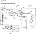
- Fig. 2 is a diagram explaining the flow of the refrigerant during the heating operation of the air-conditioning apparatus 200 illustrated in Fig. 1 .
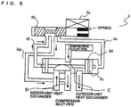
- Fig. 3 is a diagram explaining the flow of the refrigerant in the four-way valve 3 illustrated in Fig. 2 during the heating operation.
- arrows indicate the flow direction of the refrigerant.
- arrows in the refrigerant passages A and B each indicate the flow direction of the refrigerant and arrows in the pipes 3e to 3g each indicate a pressure generated in the direction indicated by the arrow.
- the controller 9 energizes the solenoid valve coil 3a of the four-way valve 3 to shift the needle valve 3b as illustrated in Fig. 3 .
- the shifting of the needle valve 3b causes the pipe 3e to communicate with the pipe 3g, so that the piston 3c in the cylinder 3d is drawn to the right in the drawing sheet of Fig. 3 by the pressure of the refrigerant flowing through the refrigerant passage B.
- the four-way valve 3 is switched such that the refrigerant flows through the refrigerant passage A connecting the discharge side of the compressor 1 and the indoor heat exchanger 7 and the refrigerant flows through the refrigerant passage B connecting the suction side of the compressor 1 and the outdoor heat exchanger 4.
- the controller 9 energizes the solenoid valve 6 to open the valve.
- the compressor 1 compresses a gas refrigerant flowing through the compressor inlet pipe 25 and discharges a high-temperature high-pressure gas refrigerant through the compressor outlet pipe 20.
- the discharged high-temperature high-pressure gas refrigerant passes through the compressor outlet pipe 20 and the check valve 2.
- the check valve 2 prevents the high-temperature high-pressure gas refrigerant from flowing backward to the compressor 1.
- the high-temperature high-pressure gas refrigerant leaving the check valve 2 flows through the gas pipe 21, the refrigerant passage A in the four-way valve 3, and the connecting pipe 24A into the indoor heat exchanger 7.
- the air-sending device 8b acts to promote heat exchange between indoor air and the high-temperature high-pressure gas refrigerant which has flowed into the indoor heat exchanger 7, so that the refrigerant transfers heat to the indoor air and thus condenses.
- the high-temperature high-pressure gas refrigerant condenses into a liquid refrigerant or a two-phase gas-liquid refrigerant in the indoor heat exchanger 7.
- the indoor air which has received heating energy from the high-temperature high-pressure gas refrigerant is supplied as heating air into an indoor space by the air-sending device 8b.
- the liquid refrigerant or two-phase gas-liquid refrigerant after condensation in the indoor heat exchanger 7 flows through the solenoid valve 6 into the expansion means 5 where the pressure of the refrigerant is reduced.
- the pressure-reduced liquid refrigerant or two-phase gas-liquid refrigerant flows through the liquid pipe 23A into the outdoor heat exchanger 4.
- the air-sending device 8a acts to promote heat exchange between outdoor air and the liquid refrigerant or two-phase gas-liquid refrigerant which has flowed into the outdoor heat exchanger 4, so that the refrigerant removes heat from the outdoor air and thus gasifies into a low-temperature low-pressure gas refrigerant.
- the low-temperature low-pressure gas refrigerant flows out of the outdoor heat exchanger 4 and flows through the outdoor pipe 22, the refrigerant passage B in the four-way valve 3, and the compressor inlet pipe 25 to the suction side of the compressor 1. Subsequently, the above-described operation is repeated.
- Fig. 4 is a diagram explaining the flow of the refrigerant during the cooling operation of the air-conditioning apparatus 200 illustrated in Fig. 1 .
- Fig. 5 is a diagram explaining the flow of the refrigerant in the four-way valve 3 illustrated in Fig. 4 during the cooling operation.
- arrows indicate the flow direction of the refrigerant.
- arrows in the refrigerant passages C and D each indicate the flow direction of the refrigerant and arrows in the pipes 3e to 3g each indicate a pressure generated in the direction indicated by the arrow.
- the controller 9 shifts the needle valve 3b as illustrated in Fig. 5 without energizing the solenoid valve coil 3a of the four-way valve 3.
- the shifting of the needle valve 3b causes the pipe 3f to communicate with the pipe 3g, so that the piston 3c in the cylinder 3d is drawn to the left in the drawing sheet of Fig. 5 by the pressure of the refrigerant flowing through the refrigerant passage D.
- the four-way valve 3 is switched such that the refrigerant flows through the refrigerant passage C connecting the discharge side of the compressor 1 and the outdoor heat exchanger 4 and the refrigerant flows through the refrigerant passage D connecting the suction side of the compressor 1 and the indoor heat exchanger 7.
- the controller 9 energizes the solenoid valve 6 to open the valve.
- the compressor 1 compresses a gas refrigerant flowing through the compressor inlet pipe 25 and discharges a high-temperature high-pressure gas refrigerant through the compressor outlet pipe 20.
- the discharged high-temperature high-pressure gas refrigerant passes through the compressor outlet pipe 20 and the check valve 2.
- the check valve 2 prevents the high-temperature high-pressure gas refrigerant from flowing backward to the compressor 1.
- the high-temperature high-pressure gas refrigerant leaving the check valve 2 flows through the gas pipe 21, the refrigerant passage C in the four-way valve 3, and the outdoor pipe 22 into the outdoor heat exchanger 4.
- the air-sending device 8a acts to promote heat exchange between outdoor air and the high-temperature high-pressure gas refrigerant which has flowed into the outdoor heat exchanger 4, so that the refrigerant transfers heat to the outdoor air and thus condenses.
- the high-temperature high-pressure gas refrigerant condenses into a liquid refrigerant or a two-phase gas-liquid refrigerant in the outdoor heat exchanger 4.
- the liquid refrigerant or two-phase gas-liquid refrigerant after condensation in the outdoor heat exchanger 4 flows through the liquid pipe 23A into the expansion means 5 where the pressure of the refrigerant is reduced.
- the pressure-reduced liquid refrigerant or two-phase gas-liquid refrigerant flows through the connecting pipe 23B, the solenoid valve 6, and the connecting pipe 24B into the indoor heat exchanger 7.
- the air-sending device 8b acts to promote heat exchange between indoor air and the liquid refrigerant or two-phase gas-liquid refrigerant which has flowed into the indoor heat exchanger 7, so that the refrigerant removes heat from the indoor air and thus gasifies into a low-temperature low-pressure gas refrigerant.
- the indoor air which has received cooling energy from the liquid refrigerant or two-phase gas-liquid refrigerant is supplied as cooling air into the indoor space by the air-sending device 8b.
- the low-temperature low-pressure gas refrigerant flows out of the indoor heat exchanger 7 and flows through the connecting pipe 24A, the refrigerant passage D in the four-way valve 3, and the compressor inlet pipe 25 to the suction side of the compressor 1. Subsequently, the above-described operation is repeated.
- Fig. 6 is a diagram illustrating a flowchart of control for the air-conditioning apparatus 200 according to Embodiment 1. An operation of the controller 9 will be described with reference to Fig. 6 .
- the controller 9 When receiving a setting instruction to start an operation from, for example, a remote control, the controller 9 starts an operation of the air-conditioning apparatus 200.
- the controller 9 controls the driving frequency of the compressor 1, the rotation speed of each of the air-sending devices 8a and 8b, and the opening degree of the expansion means 5, energizes the solenoid valve coil 3a of the four-way valve 3, and opens the solenoid valve 6.
- the controller 9 When receiving a setting instruction to stop the operation from, for example, the remote control, the controller 9 performs a refrigerant stagnation suppression control in the following steps S4 to S8.
- the controller 9 stops energizing the solenoid valve coil 3a of the four-way valve 3.
- step S4 allows switching from the heating operation to the cooling operation.
- the controller 9 determines whether a predetermined period of time (e.g., five minutes) has elapsed.
- a predetermined period of time e.g., five minutes
- step S6 When determining that the predetermined period of time has elapsed, the controller 9 proceeds to step S6.
- step S5 When determining that the predetermined period of time has not elapsed, the controller 9 repeats step S5.
- the controller 9 fully closes the solenoid valve 6.
- the controller 9 determines whether a predetermined period of time (e.g., five minutes) has elapsed.
- a predetermined period of time e.g., five minutes
- step S8 When determining that the predetermined period of time has elapsed, the controller 9 proceeds to step S8.
- step S7 When determining that the predetermined period of time has not elapsed, the controller 9 repeats step S7.
- the controller 9 stops the compressor 1.
- the processing in steps S4 to S8 allows the refrigerant to be stored in the refrigerant pipes arranged between the solenoid valve 6 and the check valve 2. More specifically, according to the processing in steps S4 to S8, the compressor 1 forces the refrigerant in the connecting pipe 24B, the indoor heat exchanger 7, the connecting pipe 24A, the refrigerant passage B in the four-way valve 3, and the compressor inlet pipe 25 to the discharge side of the compressor 1.
- the forced refrigerant is stored in a range including the check valve 2, the gas pipe 21, the refrigerant passage A in the four-way valve 3, the outdoor pipe 22, the outdoor heat exchanger 4, the liquid pipe 23A, the expansion means 5, the connecting pipe 23B, and the solenoid valve 6.
- the controller 9 controls the driving frequency of the compressor 1, the rotation speed of each of the air-sending devices 8a and 8b, and the opening degree of the expansion means 5 and opens the solenoid valve 6 without energizing the solenoid valve coil 3a of the four-way valve 3.
- step S11 the refrigerant stagnation suppression control is not performed during the cooling operation to prevent an increase in time that elapses before the operation of the air-conditioning apparatus 200 is stopped.
- the controller 9 stops the operation of the air-conditioning apparatus 200.
- the air-conditioning apparatus 200 can perform the refrigerant stagnation suppression control of stopping energizing the solenoid valve coil 3a of the four-way valve 3 to switch from the heating operation to the cooling operation and then stopping the operation of the compressor 1.
- the refrigerant can be stored in the range including the check valve 2 on the discharge side, the gas pipe 21, the refrigerant passage A in the four-way valve 3, the outdoor pipe 22, the outdoor heat exchanger 4, the liquid pipe 23A, the expansion means 5, the connecting pipe 23B, and the solenoid valve 6.
- the refrigerant can be separated from the lubricating oil in the compressor 1 and dissolution of the refrigerant in the lubricating oil can be suppressed.
- the air-conditioning apparatus 200 according to Embodiment 1 can reduce poor lubrication in the compressor 1.
- the air-conditioning apparatus 200 performs the control of stopping energizing the solenoid valve coil 3a of the four-way valve 3 for switching to the cooling operation and then stopping the operation of the compressor 1.
- the apparatus can suppress the stagnation of the refrigerant while suppressing complication of the control.
- the air-conditioning apparatus 200 can perform the refrigerant stagnation suppression control without using outdoor air temperature detecting means or the like.
- the apparatus can suppress the stagnation of the refrigerant while accordingly suppressing an increase in the number of components.
- the air-conditioning apparatus 200 can suppress the stagnation of the refrigerant by stopping energizing the solenoid valve coil 3a of the four-way valve 3 for switching to the cooling operation and then stopping the operation of the compressor 1. Consequently, if the apparatus does not include a heater or the like, the apparatus can suppress the stagnation of the refrigerant and can accordingly reduce power consumption.
- Fig. 7 illustrates an exemplary configuration of a refrigerant circuit of an air-conditioning apparatus 200b according to Embodiment 2.
- the air-conditioning apparatus 200b according to Embodiment 2 includes low pressure detecting means 10 in addition to the components of the air-conditioning apparatus 200 according to Embodiment 1.
- the low pressure detecting means 10 for detecting a pressure is disposed in the compressor inlet pipe 25 connected to the suction side of the compressor 1.
- the low pressure detecting means 10 may be, for example, a pressure sensor.
- the other components in Embodiment 2 are the same as those in Embodiment 1.
- Fig. 8 is a diagram illustrating a flowchart of control for the air-conditioning apparatus 200b according to Embodiment 2. An operation of the controller 9 will be described with reference to Fig. 8 .
- the control flowchart of Fig. 8 includes step S20 that replaces steps S7 and S8 in the flowchart of Fig. 6 . Since the other steps in Fig. 8 are the same as those in Fig. 6 , a description of the same control processing is omitted.
- the controller 9 determines whether a pressure detected by the low pressure detecting means 10 is at or below a given pressure.
- the controller 9 When determining that the detected pressure is at or below the given pressure, the controller 9 stops the compressor 1.
- the controller 9 When determining that the detected pressure is not at or below the given pressure, the controller 9 continues the operation of the compressor 1.
- the air-conditioning apparatus 200b according to Embodiment 2 offers the following advantage in addition to the advantages offered by the air-conditioning apparatus 200 according to Embodiment 1. Since the air-conditioning apparatus 200b according to Embodiment 2 stops the compressor 1 on the basis of a pressure detected by the low pressure detecting means 10, the stagnation of the refrigerant can be more reliably suppressed.
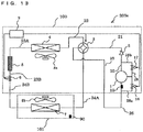
- Fig. 9 illustrates an exemplary configuration of a refrigerant circuit in an air-conditioning apparatus 200c according to Embodiment 3.
- the air-conditioning apparatus 200c according to Embodiment 3 includes the same components as those of the air-conditioning apparatus 200b according to Embodiment 2 and further includes a refrigerant pipe 26 that connects the connecting pipe 23B and the compressor 1, expansion means 11 for reducing the pressure of the refrigerant flowing through the refrigerant pipe 26, a solenoid valve 12 that switches between passing and non-passing of the refrigerant through the refrigerant pipe 26, and temperature detecting means 10A for detecting the temperature of the refrigerant flowing through the compressor outlet pipe 20.
- the refrigerant pipe 26 is a pipe that connects the connecting pipe 23B and the compressor 1. More specifically, the refrigerant pipe 26 is a pipe connecting the connecting pipe 23B and a fixed scroll (not illustrated) in the compressor 1. The expansion means 11 and the solenoid valve 12 are arranged in the refrigerant pipe 26.
- the expansion means 11 is configured to reduce the pressure of the refrigerant flowing through the refrigerant pipe 26 such that the refrigerant is expanded.
- the expansion means 11 is connected at a first end to the connecting pipe 23B and is connected at a second end to the solenoid valve 12.
- the expansion means 11 may be a component having a variably controllable opening degree, for example, an electronic expansion valve.
- the solenoid valve 12 is a valve whose opening and closing are controlled by the controller 9 and which is capable of switching between passing and non-passing of the refrigerant through the valve.
- the solenoid valve 12 is connected at a first end to the expansion means 11 and is connected at a second end to the fixed scroll in the compressor 1.
- the temperature detecting means 10A is configured to detect the temperature of the refrigerant flowing through the compressor outlet pipe 20 connecting the discharge side of the compressor 1 and the check valve 2.
- the temperature detecting means 10A is connected to the controller 9.
- the temperature detecting means 10A may be, for example, a thermistor.
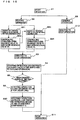
- Fig. 10 is a diagram illustrating a flowchart of control for the air-conditioning apparatus 200c according to Embodiment 3. An operation of the controller 9 will be described with reference to Fig. 10 .
- the control flowchart of Fig. 10 includes steps S31 to S34 which are added between steps S2 and S3 in the flowchart of Fig. 8 . Since the other steps in Fig. 10 are the same as those in Fig. 8 , a description of the same control processing is omitted.
- the controller 9 controls the driving frequency of the compressor 1, the rotation speed of each of the air-sending devices 8a and 8b, and the opening degree of the expansion means 5, energizes the solenoid valve coil 3a of the four-way valve 3, and opens the solenoid valve 6.
- the controller 9 determines whether a temperature detected by the temperature detecting means 10A is at or above a given temperature.
- step S31 When determining that the temperature detected by the temperature detecting means 10A is at or above the given temperature, the controller 9 proceeds to step S31.
- the controller 9 When determining that the temperature detected by the temperature detecting means 10A is below the given temperature, the controller 9 proceeds to step S33.
- step S32 Since the temperature detected by the temperature detecting means 10A is at or above the given temperature, the controller 9 proceeds to step S32.
- the controller 9 opens the solenoid valve 12.
- the controller 9 determines whether a temperature detected by the temperature detecting means 10A is at or above the given temperature.
- step S3 When determining that the temperature detected by the temperature detecting means 10A is at or above the given temperature, the controller 9 proceeds to step S3.
- the controller 9 When determining that the temperature detected by the temperature detecting means 10A is below the given temperature, the controller 9 proceeds to step S33.
- step S34 Since the temperature detected by the temperature detecting means 10A is below the given temperature, the controller 9 proceeds to step S34.
- the controller 9 closes the solenoid valve 12.
- the air-conditioning apparatus 200c according to Embodiment 3 offers the following advantages in addition to the advantages offered by the air-conditioning apparatuses according to Embodiments 1 and 2. Specifically, the air-conditioning apparatus 200c according to Embodiment 3 controls opening and closing of the solenoid valve 12 so that the liquid refrigerant or two-phase gas-liquid refrigerant leaving the solenoid valve 6 flows through the refrigerant pipe 26 into the fixed scroll in the compressor 1 during the heating operation. This allows the circulation amount of refrigerant flowing into the compressor 1 to be increased, thus increasing heating capacity.
- the temperature of the high-temperature high-pressure gas refrigerant obtained by compression through the compressor 1 is reduced by the liquid refrigerant or two-phase gas-liquid refrigerant leaving the indoor heat exchanger 7.
- the temperature of the refrigerant discharged from the compressor 1 during the heating operation can be reduced, so that the compressor 1 can be stably operated.
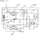
- Fig. 11 illustrates an exemplary configuration of a refrigerant circuit of an air-conditioning apparatus 200d according to Embodiment 4.
- the air-conditioning apparatus 200d according to Embodiment 4 includes the same components as those of the air-conditioning apparatus 200c according to Embodiment 3 and further includes a gas pipe 27 that connects the refrigerant pipe 26 and the compressor inlet pipe 25, a solenoid valve 13 disposed in the gas pipe 27, and temperature detecting means 90 for detecting the temperature of an air-conditioning target space.
- the air-conditioning target space is an indoor space.
- the gas pipe 27 is a pipe that connects the compressor inlet pipe 25 and a point of the refrigerant pipe 26 between the solenoid valve 12 and the compressor 1.
- the solenoid valve 13 is disposed in the gas pipe 27.
- the solenoid valve 13 is a valve whose opening and closing are controlled by the controller 9 and which is capable of switching between passing and non-passing of the refrigerant through the valve.
- the solenoid valve 13 is connected at a first end to the gas pipe 27 adjacent to the refrigerant pipe 26 and is connected at a second end to the gas pipe 27 adjacent to the compressor inlet pipe 25.
- the temperature detecting means 90 is configured to detect the temperature of the air-conditioning target space (e.g., an indoor space).
- the temperature detecting means 90 is connected to the controller 9.
- the temperature detecting means 90 may be, for example, a thermistor.
- Fig. 12 is a diagram illustrating a flowchart of control for the air-conditioning apparatus 200d according to Embodiment 4. An operation of the controller 9 will be described with reference to Fig. 12 .
- the control flowchart of Fig. 12 includes steps S41 to S44 which are added between steps S34 and S3 in the flowchart of Fig. 10 . Since the other steps in Fig. 12 are the same as those in Fig. 10 , a description of the same control processing is omitted.
- the controller 9 closes the solenoid valve 12.
- the controller 9 determines whether a detected indoor air temperature is at or above a given temperature.
- step S41 When determining that the detected indoor air temperature is at or above the given temperature, the controller 9 proceeds to step S41.
- step S43 When determining that the detected indoor air temperature is below the given temperature, the controller 9 proceeds to step S43.
- step S42 Since the detected indoor air temperature is at or above the given temperature, the controller 9 proceeds to step S42.
- the controller 9 opens the solenoid valve 13.
- the controller 9 determines whether a detected indoor air temperature is at or above the given temperature.
- step S3 When determining that the detected indoor air temperature is at or above the given temperature, the controller 9 proceeds to step S3.
- the controller 9 When determining that the detected indoor air temperature is below the given temperature, the controller 9 proceeds to step S43 and then proceeds to S44.
- the controller 9 closes the solenoid valve 13. After that, the controller 9 proceeds to step S3.
- the controller 9 stops energizing the solenoid valve 12 and the solenoid valve 13 to close these valves, so that the high-temperature high-pressure gas refrigerant compressed in the compressor 1 is discharged through the compressor outlet pipe 20.
- the controller 9 continues to stop energizing the solenoid valve 12 such that the solenoid valve 12 is kept closed and energizes the solenoid valve 13 to open the valve. This enables an intermediate-temperature intermediate-pressure gas refrigerant compressed in the compressor 1 to escape from the compressor 1 through the refrigerant pipe 26, the gas pipe 27, and the compressor inlet pipe 25.
- the air-conditioning apparatus 200d according to Embodiment 4 offers the following advantages in addition to the advantages offered by the air-conditioning apparatuses according to Embodiments 1 to 3.
- the air-conditioning apparatus 200d according to Embodiment 4 can control the amount of gas refrigerant to be supplied to the compressor 1 on the basis of an indoor air temperature.
- the apparatus since the air-conditioning apparatus 200d according to Embodiment 4 can control the amount of gas refrigerant to be compressed in the compressor 1 on the basis of the indoor air temperature, the apparatus can control the capacity of the compressor 1 without stopping the operation of the compressor 1, thus reducing power consumption.
- the air-conditioning apparatus 200d according to Embodiment 4 can control the capacity of the compressor 1 without stopping the operation of the compressor 1, the frequency of activating and stopping the compressor 1 can accordingly be reduced. Thus, a load applied to a bearing included in the compressor 1 when the compressor 1 is activated can be reduced.
- the air-conditioning apparatus 200d according to Embodiment 4 includes the compressor 1 that is highly reliable.
- Fig. 13 illustrates an exemplary configuration of a refrigerant circuit of an air-conditioning apparatus 200e according to Embodiment 5.
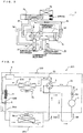
- Fig. 14A and Fig. 14B include diagrams explaining the flow of the refrigerant in the compressor 1 of the air-conditioning apparatus 200e according to Embodiment 5.
- Fig. 14A illustrates the flow of the refrigerant in the compressor 1 at an indoor air temperature lower than a setting temperature and
- Fig. 14B illustrates the flow of the refrigerant in the compressor 1 at an indoor air temperature higher than or equal to the setting temperature.
- the air-conditioning apparatus 200e according to Embodiment 5 includes the same components as those of the air-conditioning apparatus 200b according to Embodiment 2 and further includes a gas pipe 28a connected to the compressor inlet pipe 25, a gas pipe 28b connected to the compressor outlet pipe 20, a solenoid valve 16 connected at a first end to the gas pipe 28a, a solenoid valve 17 connected at a first end to the gas pipe 28b, and a gas pipe 28 connected to a second end of the solenoid valve 16, a second end of the solenoid valve 17, and the compressor 1.
- the air-conditioning apparatus 200e according to Embodiment 5 includes a spring 15 and a valve 14 for providing a gas seal in the compressor 1.
- the compressor 1 includes a sealed container 80 that serves as an outer casing of the compressor 1.
- the sealed container 80 accommodates at least, for example, a fixed scroll 81 having a fixed scroll lap 81A for compressing a fluid and an orbiting scroll 82 having an orbiting scroll lap 82Afor compressing the fluid.
- the fixed scroll 81 is configured to compress the fluid together with the orbiting scroll 82.
- the fixed scroll 81 is disposed so as to face the orbiting scroll 82.
- An upper surface of the fixed scroll 81 is connected to the gas pipe 28.
- the fixed scroll 81 includes a refrigerant discharge passage 83A through which the refrigerant compressed by the fixed scroll 81 and the orbiting scroll 82 is discharged.
- the refrigerant discharge passage 83A extends vertically.
- the fixed scroll 81 further includes a refrigerant discharge passage 83B that communicates between the refrigerant discharge passage 83A and the sealed container 80.
- the refrigerant discharge passage 83B extends horizontally.
- the gas pipe 28a is connected at a first end to the compressor inlet pipe 25 and is connected at a second end to the solenoid valve 16.
- the gas pipe 28b is connected at a first end to the compressor outlet pipe 20 and is connected at a second end to the solenoid valve 17.
- the gas pipe 28 is connected to the second end of the solenoid valve 16, the second end of the solenoid valve 17, and the fixed scroll 81 of the compressor 1.
- Each of the solenoid valves 16 and 17 is a valve whose opening and closing are controlled by the controller 9 and which is capable of switching between passing and non-passing of the refrigerant through the valve.
- the solenoid valve 16 is connected at the first end to the gas pipe 28a and is connected at the second end to the gas pipe 28.
- the solenoid valve 17 is connected at the first end to the gas pipe 28b and is connected at the second end to the gas pipe 28.
- valve 14 When the refrigerant is supplied through the gas pipe 28, the valve 14 is pressed together with the spring 15 against the fixed scroll 81 to block (seal) the communication between the refrigerant discharge passages 83A and 83B. While the refrigerant is not supplied through the gas pipe 28, the refrigerant supplied through the refrigerant discharge passage 83A causes the spring 15 to extend upward and presses the valve 14 upward, thus allowing the refrigerant discharge passage 83A to communicate with the refrigerant discharge passage 83B.
- the spring 15 is disposed in upper part of the fixed scroll 81 so as to coincide with the refrigerant discharge passage 83A.
- the spring 15 is disposed so as to contract when the valve 14 is forced downward by the gas refrigerant supplied through the gas pipe 28. The contracting of the spring 15 blocks the communication between the refrigerant discharge passages 83A and 83B.
- the spring 15 has a function of, upon contracting, preventing the refrigerant compressed by the fixed scroll 81 and the orbiting scroll 82 from flowing from the refrigerant discharge passage 83A to the refrigerant discharge passage 83B and has a function of, upon extending, permitting the refrigerant compressed by the fixed scroll 81 and the orbiting scroll 82 to flow from the refrigerant discharge passage 83A to the refrigerant discharge passage 83B.
- Embodiment 5 has been described with respect to an implementation using the spring 15, Embodiment 5 is not intended to be limited to this implementation.
- a rubber-like member may be substituted for the spring 15.
- Fig. 15 is a diagram illustrating a flowchart of control for the air-conditioning apparatus 200e according to Embodiment 5. An operation of the controller 9 will be described with reference to Fig. 15 .
- the control flowchart of Fig. 15 includes steps S51 to S54 which are added between steps S2 and S3 in the flowchart of Fig. 8 . Since the other steps in Fig. 15 are the same as those in Fig. 8 , a description of the same control processing is omitted.
- the controller 9 controls the driving frequency of the compressor 1, the rotation speed of each of the air-sending devices 8a and 8b, and the opening degree of the expansion means 5, energizes the solenoid valve coil 3a of the four-way valve 3, and opens the solenoid valve 6.
- the controller 9 determines whether a detected indoor air temperature is at or above a given temperature.
- step S51 When determining that the detected indoor air temperature is at or above the given temperature, the controller 9 proceeds to step S51.
- step S53 When determining that the detected indoor air temperature is below the given temperature, the controller 9 proceeds to step S53.
- the controller 9 proceeds to step S52.
- the controller 9 opens the solenoid valve 16 and closes the solenoid valve 17.
- the controller 9 determines whether a detected indoor air temperature is at or above the given temperature.
- step S3 When determining that the detected indoor air temperature is at or above the given temperature, the controller 9 proceeds to step S3.
- step S53 When determining that the detected indoor air temperature is below the given temperature, the controller 9 proceeds to step S53.
- step S54 Since the detected indoor air temperature is below the given temperature, the controller 9 proceeds to step S54.
- the controller 9 closes the solenoid valve 16 and opens the solenoid valve 17.
- the air-conditioning apparatus 200e according to Embodiment 5 can control the amount of gas refrigerant to be compressed in the compressor 1 depending on an indoor air temperature at or above the given temperature and an indoor air temperature below the given temperature.
- the controller 9 opens the solenoid valve 16 and closes the solenoid valve 17. Consequently, an intermediate-temperature intermediate-pressure gas refrigerant compressed by the fixed scroll 81 and the orbiting scroll 82 of the compressor 1 upwardly presses the valve 14 and the spring 15 and flows through the refrigerant discharge passages 83A and 83B into the sealed container 80.
- the controller 9 controls the amount of refrigerant so that an excess of refrigerant is not supplied to the compressor outlet pipe 20 (see Fig. 14B ).
- the controller 9 closes the solenoid valve 16 and opens the solenoid valve 17. Consequently, the intermediate-temperature intermediate-pressure gas refrigerant compressed by the fixed scroll 81 and the orbiting scroll 82 of the compressor 1 flows through the compressor outlet pipe 20, so that part of the refrigerant flowing through the compressor outlet side pipe 20 flows through the gas pipe 28b into the compressor 1.
- the refrigerant which has flowed into the compressor 1 downwardly presses the valve 14 and the spring 15 to block the communication between the refrigerant discharge passages 83A and 83B.
- the controller 9 prevents the refrigerant compressed by the fixed scroll 81 and the orbiting scroll 82 from escaping through the refrigerant discharge passage 83B and controls the refrigerant such that the refrigerant is reliably discharged through the compressor outlet pipe 20 (see Fig. 14A ).
- the air-conditioning apparatus 200e according to Embodiment 5 offers the following advantages in addition to the advantages offered by the air-conditioning apparatuses according to Embodiments 1 and 2. Since the air-conditioning apparatus 200e according to Embodiment 5 can control the amount of gas refrigerant to be supplied from the compressor 1 to the refrigerant circuit on the basis of an indoor air temperature, the apparatus can control the capacity of the compressor 1 without stopping the operation of the compressor 1, thus reducing power consumption.
- the air-conditioning apparatus 200e according to Embodiment 5 can control the capacity of the compressor 1 without stopping the operation of the compressor 1, the frequency of activating and stopping the compressor 1 can accordingly be reduced, thus reducing a load applied to the bearing included in the compressor 1 when the compressor 1 is activated.
- the air-conditioning apparatus 200e according to Embodiment 5 can include the compressor 1 that is highly reliable.
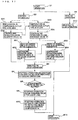
- Fig. 16 illustrates an exemplary configuration of a refrigerant circuit of an air-conditioning apparatus 200f according to Embodiment 6.
- Fig. 17 is a diagram illustrating a flowchart of control for the air-conditioning apparatus 200f according to Embodiment 6.
- Embodiment 6 provides a configuration obtained by combining the configurations in Embodiments 2, 3, and 5.
- the air-conditioning apparatus 200f includes the refrigerant pipe 26, the expansion means 11, the solenoid valve 12, and the temperature detecting means 10A in Embodiment 3, and further includes the gas pipe 28a, the gas pipe 28b, the solenoid valve 16, the solenoid valve 17, the gas pipe 28, and the spring 15 and the valve 14 of the compressor 1 in Embodiment 5.
- step S3 follows step S34 in Embodiment 3
- step S51 or step S53 in Embodiment 5 follows step S34 in Embodiment 6.
- the flowchart of Fig. 17 will be described mainly with respect to parts peculiar to Embodiment 6.
- the controller 9 controls the driving frequency of the compressor 1, the rotation speed of each of the air-sending devices 8a and 8b, and the opening degree of the expansion means 5, energizes the solenoid valve coil 3a of the four-way valve 3, and opens the solenoid valve 6.
- the controller 9 determines whether a temperature detected by the temperature detecting means 10A is at or above a given temperature.
- step S31 When determining that the temperature detected by the temperature detecting means 10A is at or above the given temperature, the controller 9 proceeds to step S31.
- the controller 9 When determining that the temperature detected by the temperature detecting means 10A is below the given temperature, the controller 9 proceeds to step S33.
- step S32 Since the temperature detected by the temperature detecting means 10A is at or above the given temperature, the controller 9 proceeds to step S32.
- the controller 9 opens the solenoid valve 12.
- the controller 9 determines whether a temperature detected by the temperature detecting means 10A is at or above the given temperature.
- step S3 When determining that the temperature detected by the temperature detecting means 10A is at or above the given temperature, the controller 9 proceeds to step S3.
- the controller 9 When determining that the temperature detected by the temperature detecting means 10A is below the given temperature, the controller 9 proceeds to step S33.
- step S34 Since the temperature detected by the temperature detecting means 10A is below the given temperature, the controller 9 proceeds to step S34.
- the controller 9 closes the solenoid valve 12.
- the controller 9 determines whether an indoor air temperature is at or above a given temperature.
- step S51 When determining that a detected indoor air temperature is at or above the given temperature, the controller 9 proceeds to step S51.
- step S53 When determining that the detected indoor air temperature is below the given temperature, the controller 9 proceeds to step S53.
- the controller 9 proceeds to step S52.
- the controller 9 opens the solenoid valve 16 and closes the solenoid valve 17.
- the controller 9 determines whether a detected indoor air temperature is at or above the given temperature.
- step S3 When determining that the detected indoor air temperature is at or above the given temperature, the controller 9 proceeds to step S3.
- step S53 When determining that the detected indoor air temperature is below the given temperature, the controller 9 proceeds to step S53.
- step S54 Since the detected indoor air temperature is below the given temperature, the controller 9 proceeds to step S54.
- the controller 9 closes the solenoid valve 16 and opens the solenoid valve 17.
- the air-conditioning apparatus according to Embodiment 6 offers the same advantages as those offered by the air-conditioning apparatuses according to Embodiments 1 to 5.
- An air-conditioning apparatus has the same configuration as that of any of the air-conditioning apparatuses 200 and 200b to 200f according to Embodiments 1 to 6 and is capable of performing a defrosting operation as control.
- the air-conditioning apparatus can perform the defrosting operation by performing processing in step S4 in Figs. 6 , 8 , 10 , 12 , 15 , and 17 in the following manner.
- the controller 9 stops energizing the solenoid valve coil 3a of the four-way valve 3.
- This processing in step S4 allows switching from the heating operation to the cooling operation.
- the controller 9 Upon stopping energizing the solenoid valve coil 3a of the four-way valve 3, the controller 9 stops the operation of each of the air-sending devices 8a and 8b.
- frost may accumulate on the outdoor heat exchanger 4 functioning as an evaporator during the heating operation
- switching to the cooling operation in step S4 as described above causes a hot gas to be supplied to the outdoor heat exchanger 4, thus removing frost.
- the air-conditioning apparatus according to Embodiment 7 stops the operation of the air-sending device 8a in step S4, the supply of cold outdoor air to the outdoor heat exchanger 4 is suppressed, so that frost accumulated on the outdoor heat exchanger 4 can be reliably removed.
- the air-sending device 8b since the operation of the air-sending device 8b is also stopped, the supply of air which has received cooling energy through the indoor heat exchanger 7, functioning as an evaporator, into an indoor space is suppressed. This prevents a user from feeling uncomfortable.
- the air-conditioning apparatus according to Embodiment 7 offers the following advantages in addition to the advantages offered by the air-conditioning apparatuses according to Embodiments 1 to 6. Specifically, since the air-conditioning apparatus according to Embodiment 7 stops the air-sending device 8a when switching from the heating operation to the cooling operation in order to perform the refrigerant stagnation suppression control, frost accumulated on the outdoor heat exchanger 4 can be reliably removed.
- Embodiment 7 further stops the air-sending device 8b when switching from the heating operation to the cooling operation in order to perform the refrigerant stagnation suppression control, the supply into the indoor spaces of air which has received cooling energy through the indoor heat exchanger 7 functioning as an evaporator is suppressed, thus preventing the user from feeling uncomfortable.
- An air-conditioning apparatus is the air-conditioning apparatus according to any of Embodiments 1 to 7 installed on a railway vehicle such that the compressor of the air-conditioning apparatus according to any of Embodiments 1 to 7 is "horizontally mounted" on the railway vehicle.
- a railway vehicle such as a train other than the Shinkansen bullet train, has a limited mounting space and a compressor is accordingly mounted horizontally thereon.
- an air-conditioning apparatus is installed on the roof of a railway vehicle, such as a train, and a compressor is "horizontally mounted” because a mounting space on the roof is limited.
- horizontal mounting means mounting the compressor 1 such that a direction in which, for example, the orbiting scroll (see Fig. 14A and Fig. 14B ) slides is substantially perpendicular to a horizontal plane.
- the level of a liquid may suddenly rise due to the stagnation of a refrigerant or the return of a liquid refrigerant to the compressor, so that a fixed scroll lap of a fixed scroll (see Fig. 14A and Fig. 14B ) and an orbiting scroll lap of an orbiting scroll may soak in the liquid refrigerant.
- a fixed scroll lap of a fixed scroll see Fig. 14A and Fig. 14B
- an orbiting scroll lap of an orbiting scroll may soak in the liquid refrigerant.
- the supply of the liquid refrigerant to the fixed scroll lap and the orbiting scroll lap, which are used to compress a gas refrigerant may result in breakage of the scroll laps.
- Typical train operating time per day is about eight hours (depending on operating efficiency).
- An air-conditioning apparatus is energized through a pantograph during that time and the apparatus is de-energized while a corresponding railway vehicle is subjected to maintenance or stopped. For example, if a crankcase heater for separating a liquid refrigerant and a lubricating oil is attached to the compressor, the heater cannot be used while the air-conditioning apparatus is de-energized because of the maintenance or the like, so that the stagnation of the refrigerant may fail to be suppressed.
- the air-conditioning apparatus can suppress the stagnation of the refrigerant and accordingly protect the fixed scroll lap and the orbiting scroll lap against soaking in the liquid refrigerant, thus preventing breakage of the fixed scroll lap and the orbiting scroll lap caused by the supply of the liquid refrigerant to these scroll laps.
- the refrigerant can be stored in a range including the check valve 2 on the discharge side, the gas pipe 21, the refrigerant passage A of the four-way valve 3, the outdoor pipe 22, the outdoor heat exchanger 4, the liquid pipe 23A, the expansion means 5, the connecting pipe 23B, and the solenoid valve 6.
- the air-conditioning apparatus according to Embodiment 8 can suppress returning of the liquid refrigerant to the compressor and accordingly protect the fixed scroll lap and the orbiting scroll lap against soaking in the liquid refrigerant, thus preventing the breakage of the fixed scroll lap and the orbiting scroll lap caused by the supply of the liquid refrigerant to these scroll laps.
- Embodiment 8 can suppress the stagnation of the refrigerant if a crankcase heater cannot be used while power supply through the pantograph is stopped, the fixed scroll lap and the orbiting scroll lap can be protected against soaking in the liquid refrigerant, thus preventing the breakage of the fixed scroll lap and the orbiting scroll lap caused by the supply of the liquid refrigerant to these scroll laps.
- crankcase heater may be eliminated from the air-conditioning apparatus according to Embodiment 8 because the apparatus can suppress the stagnation of the refrigerant.
Landscapes
- Engineering & Computer Science (AREA)
- Physics & Mathematics (AREA)
- Mechanical Engineering (AREA)
- Thermal Sciences (AREA)
- General Engineering & Computer Science (AREA)
- Fluid Mechanics (AREA)
- Air Conditioning Control Device (AREA)
- Compression-Type Refrigeration Machines With Reversible Cycles (AREA)
- Magnetically Actuated Valves (AREA)
Claims (9)
- Klimaanlage (200, 200b-200f) umfasst einen Verdichter (1), ein Vierwegeventil (3), einen Außenwärmetauscher (4), eine Expansionsvorrichtung (5) und einen Innenwärmetauscher (7), die durch Kältemittelleitungen verbunden sind, um einen Kältekreislauf darzustellen;
ein Absperrventil (2), das zwischen einer Abgabeseite des Verdichters (1) und dem Vierwegeventil (3) angeordnet ist;
ein erstes Magnetventil (6), das zwischen der Expansionsvorrichtung (5) und dem Innenwärmetauscher (7) angeordnet und zum Öffnen und Schließen steuerbar ist; und
eine Steuereinheit (9), die das Vierwegeventil (3) umschaltet und das erste Magnetventil (6) zwischen geöffneten und geschlossenen Zuständen umschaltet, dadurch gekennzeichnet, dass
wenn Heizbetrieb gestoppt ist, die Steuereinheit (9) das Vierwegeventil (3) von Verbindung für den Heizbetrieb zu Verbindung für den Kühlbetrieb umschaltet, das erste Magnetventil (6) schließt und dann den Verdichter (1) anhält. - Klimaanlage (200, 200b-200f) nach Anspruch 1, ferner umfassend:eine Niederdruck-Erfassungsvorrichtung (10) zum Erfassen des Drucks eines zwischen einer Ansaugseite des Verdichters (1) und dem Vierwegeventil (3) strömenden Kältemittels,wobei die Steuereinheit (9) das Vierwegeventil (3) von der Verbindung für den Heizbetrieb zu der Verbindung für den Kühlbetrieb umschaltet und das erste Magnetventil (6) schließt, undwobei die Steuereinheit (9) den Verdichter (1) anhält, wenn ein durch die Niederdruck-Erfassungsvorrichtung (10) erfasster Druck bei oder unter einem gegebenen Druck liegt.
- Klimaanlage (200, 200b-200f) nach Anspruch 1 oder 2, ferner umfassend:eine erste Temperaturerfassungsvorrichtung (10A) zum Erfassen der Temperatur des zwischen einer Abgabeseite des Verdichters (1) und dem Vierwegeventil (3) strömenden Kältemittels,eine Kältemittelleitung, die den Verdichter (1) und einen Punkt zwischen der Expansionsvorrichtung (5) und dem Magnetventil (6) verbindet; undein zweites Magnetventil (12), das in der Kältemittelleitung angeordnet und zum Öffnen und Schließen steuerbar ist,wobei die Steuereinheit (9) das zweite Magnetventil (12) öffnet, wenn eine durch die erste Temperaturerfassungsvorrichtung (10A) erfasste Temperatur bei oder über einer gegebenen Temperatur liegt, um ein flüssiges Kältemittel oder ein ZweiPhasen-Kältemittel in den Verdichter (1) einzuspritzen, undwobei die Steuereinheit (9) das zweite Magnetventil (12) schließt, wenn die durch die erste Temperaturerfassungsvorrichtung (10A) erfasste Temperatur unter der gegebenen Temperatur liegt.
- Klimaanlage (200, 200b-200f) nach Anspruch 3, ferner umfassend:eine zweite Temperaturerfassungsvorrichtung (90) zum Erfassen der Temperatur eines Klimaanlagenzielbereichs;eine erste Gasleitung (27), die die Ansaugseite des Verdichters (1) und einen Punkt der Kältemittelleitung zwischen dem zweiten Magnetventil (12) und dem Verdichter (1) verbindet; undein drittes Magnetventil (13), das in der ersten Gasleitung (27) angeordnet und zum Öffnen und Schließen steuerbar ist,wobei die Steuereinheit (9) beim Schließen des zweiten Magnetventils (12) das dritte Magnetventil (13) öffnet, wenn eine durch die zweite Temperaturerfassungsvorrichtung (90) erfasste Temperatur bei oder über einer gegebenen Temperatur liegt, um ein Zwischentemperatur-Zwischendruck-Kältemittel durch die Kältemittelleitung und die erste Gasleitung (27) zur Ansaugseite des Verdichters (1) in den Verdichter (1) zurückzuführen.
- Klimaanlage (200, 200b-200f) nach einem der Ansprüche 1 bis 3, ferner umfassend:eine zweite Temperaturerfassungsvorrichtung (90) zum Erfassen der Temperatur eines Klimaanlagenzielbereichs;eine zweite Gasleitung (28, 28a, 28b), die die Abgabeseite des Verdichters (1), die Ansaugseite des Verdichters (1) und das Innere des Verdichters (1) verbindet; und ein viertes Magnetventil (16, 17), das das Umschalten zwischen dem Verbinden der Abgabeseite und dem Inneren des Verdichters (1) und dem Verbinden der Ansaugseite und dem Inneren des Verdichters (1) ermöglicht; undwobei der Verdichter (1) umfasst:einen verschlossenen Behälter (80) in dem das von der Ansaugseite des Verdichters (1) zugeführte Kältemittel gespeichert ist,eine feste Spirale (81), die in dem verschlossenen Behälter (80) angeordnet ist, wobei die feste Spirale (81) eine feste Spiralrunde (81A) aufweist, undeine umlaufende Spirale (82), die in dem verschlossenen Behälter (80) angeordnet ist, wobei die umlaufende Spirale (82) eine umlaufende Spiralrunde (82A) auf einer Oberfläche derselben aufweist, wobei die umlaufende Spiralrunde (82A) der festen Spiralrunde (81A) entspricht, wobei die feste Spirale (81) umfasst:einen Kältemittelabgabedurchgang, durch den das durch die feste Spirale (81) und die umlaufende Spirale (82) verdichtete Kältemittel in den verschlossenen Behälter (80) strömt, undeine Öffnungs- und Schließvorrichtung (14, 15), die an einem Ende der zweiten Gasleitung (28, 28a, 28b) angeordnet ist, um den Kältemittelabgabedurchgang in Abhängigkeit von dem Druck des durch die zweite Gasleitung (28, 28a, 28b) zugeführten Kältemittels zu öffnen oder zu schließen.
- Klimaanlage (200, 200b-200f) nach Anspruch 5,
wobei die Steuereinheit (9) das vierte Magnetventil (16, 17) steuert, wenn eine durch die zweite Temperaturerfassungsvorrichtung (90) erfasste Temperatur unter einer gegebenen Temperatur liegt, um den Kältemittelabgabedurchgang so zu schließen, dass das Kältemittel von der Abgabeseite des Verdichters (1) der Öffnungs- und Schließvorrichtung (14, 15) zugeführt wird, und
wobei die Steuereinheit (9) das vierte Magnetventil (16, 17) steuert, wenn die durch die zweite Temperaturerfassungsvorrichtung (90) erfasste Temperatur bei oder über der gegebenen Temperatur liegt, um Kommunikation zwischen dem Inneren des Verdichters (1) und der Ansaugseite des Verdichters (1) herzustellen und dabei das Kältemittel, das durch den Kältemittelabgabedurchgang in den verschlossenen Behälter (80) zur Ansaugseite des Verdichters (1) geströmt ist, zurückzuführen. - Klimaanlage (200, 200b-200f) nach Anspruch 5 in Abhängigkeit von Anspruch 3 oder Anspruch 6 in Abhängigkeit von Anspruch 5 in Abhängigkeit von Anspruch 3,
wobei die Steuereinheit (9) beim Schließen des zweiten Magnetventils (12) das vierte Magnetventil (16, 17) steuert, wenn eine durch die zweite Temperaturerfassungsvorrichtung (90) erfasste Temperatur unter einer gegebenen Temperatur liegt, um den Kältemittelabgabedurchgang so zu schließen, dass das Kältemittel von der Abgabeseite des Verdichters (1) zur Öffnungs- und Schließvorrichtung (14, 15) zugeführt wird, und
wobei die Steuereinheit (9) beim Schließen des zweiten Magnetventils (12) das vierte Magnetventil (16, 17) steuert, wenn die durch die zweite Temperaturerfassungsvorrichtung (90) erfasste Temperatur bei oder über der gegebenen Temperatur liegt, um Kommunikation zwischen dem Inneren des Verdichters (1) und der Ansaugseite des Verdichters (1) herzustellen und dabei das Kältemittel, das durch den Kältemittelabgabedurchgang in den verschlossenen Behälter (80) zur Ansaugseite des Verdichters (1) geströmt ist, zurückzuführen. - Klimaanlage (200, 200b-200f) nach einem der Ansprüche 1 bis 7, ferner umfassend:eine erste Luftzuführungseinrichtung (8b), die dem Innenwärmetauscher (7) Luft zuführt; undeine zweite Luftzuführungseinrichtung (8a), die dem Außenwärmetauscher (4) Luft zuführt; undwobei die Steuereinheit (9) das Vierwegeventil (3) von der Verbindung für den Heizbetrieb zu der Verbindung für den Kühlbetrieb umschaltet und einen Betrieb der ersten Luftzuführungseinrichtung (8b) und den der zweiten Luftzuführungseinrichtung (8a) anhält.
- Schienenfahrzeug-Klimaanlage (200, 200b-200f), die die Klimaanlage (200, 200b-200f) ist, nach einem der Ansprüche 1 bis 8 eingerichtet auf einem Fahrzeug
wobei der Verdichter (1) horizontal befestigt ist.
Applications Claiming Priority (1)
| Application Number | Priority Date | Filing Date | Title |
|---|---|---|---|
| PCT/JP2012/000700 WO2013114461A1 (ja) | 2012-02-02 | 2012-02-02 | 空気調和装置及び鉄道車両用空気調和装置 |
Publications (3)
| Publication Number | Publication Date |
|---|---|
| EP2811241A1 EP2811241A1 (de) | 2014-12-10 |
| EP2811241A4 EP2811241A4 (de) | 2016-01-13 |
| EP2811241B1 true EP2811241B1 (de) | 2019-07-24 |
Family
ID=48904552
Family Applications (1)
| Application Number | Title | Priority Date | Filing Date |
|---|---|---|---|
| EP12867535.2A Active EP2811241B1 (de) | 2012-02-02 | 2012-02-02 | Klimaanlageneinheit und klimaanlageneinheit für schienenfahrzeug |
Country Status (5)
| Country | Link |
|---|---|
| US (1) | US9796398B2 (de) |
| EP (1) | EP2811241B1 (de) |
| JP (1) | JP5800917B2 (de) |
| CN (1) | CN104094067B (de) |
| WO (1) | WO2013114461A1 (de) |
Families Citing this family (5)
| Publication number | Priority date | Publication date | Assignee | Title |
|---|---|---|---|---|
| JP6402424B2 (ja) * | 2014-09-29 | 2018-10-10 | サンデンホールディングス株式会社 | 車両用空気調和装置 |
| CN105042733A (zh) * | 2015-06-08 | 2015-11-11 | 四川天喜车用空调有限公司 | 冷热一体化客车空调 |
| DE102016215689A1 (de) * | 2016-08-22 | 2018-02-22 | Siemens Aktiengesellschaft | Klimaanlage für ein Schienenfahrzeug |
| EP3543540B1 (de) * | 2016-11-18 | 2020-10-21 | Mitsubishi Electric Corporation | Propellergebläse und kühlkreislaufvorrichtung |
| US12320562B1 (en) | 2022-05-13 | 2025-06-03 | Parker-Hannifin Corporation | Air conditioning and heat pump system with bulbless thermostatic expansion valve |
Family Cites Families (29)
| Publication number | Priority date | Publication date | Assignee | Title |
|---|---|---|---|---|
| JPS626716A (ja) | 1985-07-04 | 1987-01-13 | Kawasaki Steel Corp | 温間圧延における圧延油供給方法 |
| JPS62228846A (ja) * | 1986-03-31 | 1987-10-07 | 三菱電機株式会社 | 空気調和装置 |
| JPS62233655A (ja) * | 1986-04-01 | 1987-10-14 | 松下電器産業株式会社 | ヒ−トポンプ式空調機 |
| US5076067A (en) * | 1990-07-31 | 1991-12-31 | Copeland Corporation | Compressor with liquid injection |
| JP3235262B2 (ja) | 1992-04-21 | 2001-12-04 | ダイキン工業株式会社 | 空気調和装置の運転制御装置 |
| JPH0828969A (ja) * | 1994-07-15 | 1996-02-02 | Sanyo Electric Co Ltd | 冷却装置 |
| JPH08166171A (ja) * | 1994-12-13 | 1996-06-25 | Mitsubishi Heavy Ind Ltd | 分離型空気調和機 |
| ES2137808B1 (es) * | 1996-05-03 | 2000-08-16 | Electrolux Espana S A | Sistema de refrigeracion mejorado. |
| JPH1144296A (ja) * | 1997-07-28 | 1999-02-16 | Matsushita Electric Ind Co Ltd | 横型スクロール圧縮機 |
| JP3462785B2 (ja) * | 1999-03-26 | 2003-11-05 | 三洋電機株式会社 | 冷凍装置 |
| JP2001089737A (ja) | 1999-09-22 | 2001-04-03 | Denki Kagaku Kogyo Kk | 水系接着剤 |
| JP2003336688A (ja) * | 2002-05-23 | 2003-11-28 | Hitachi Ltd | 回転体機器 |
| KR20040045093A (ko) * | 2002-11-22 | 2004-06-01 | 엘지전자 주식회사 | 히트펌프 시스템의 냉/난방 제어방법 |
| KR100457569B1 (ko) * | 2002-11-22 | 2004-11-18 | 엘지전자 주식회사 | 히트펌프 시스템의 전자 팽창밸브 제어방법 |
| CN100412464C (zh) | 2003-03-17 | 2008-08-20 | 松下电器产业株式会社 | 空调机 |
| JP4164566B2 (ja) * | 2003-11-07 | 2008-10-15 | 日立アプライアンス株式会社 | 空気調和装置 |
| JP2005240561A (ja) * | 2004-02-24 | 2005-09-08 | Matsushita Electric Ind Co Ltd | 膨張機 |
| JP2005337654A (ja) * | 2004-05-31 | 2005-12-08 | Denso Corp | 冷凍サイクル装置 |
| EP3096017B1 (de) * | 2004-12-22 | 2020-08-26 | Mitsubishi Denki Kabushiki Kaisha | Spiralverdichter |
| JP4793267B2 (ja) * | 2004-12-22 | 2011-10-12 | 三菱電機株式会社 | スクロール圧縮機 |
| JP4732446B2 (ja) * | 2005-03-28 | 2011-07-27 | 三菱電機株式会社 | スクロール圧縮機 |
| US7234311B2 (en) * | 2005-04-04 | 2007-06-26 | Carrier Corporation | Prevention of compressor unpowered reverse rotation in heat pump units |
| JPWO2007083794A1 (ja) * | 2006-01-20 | 2009-06-18 | 三洋電機株式会社 | 空気調和装置 |
| JP2007261321A (ja) * | 2006-03-27 | 2007-10-11 | Denso Corp | 車両用空調装置 |
| KR100791121B1 (ko) * | 2006-10-10 | 2008-01-02 | 주식회사 대우일렉트로닉스 | 공기 조화기의 정지 운전 제어 방법 |
| JP2008164227A (ja) * | 2006-12-28 | 2008-07-17 | Daikin Ind Ltd | 冷凍装置 |
| JP2008209036A (ja) * | 2007-02-23 | 2008-09-11 | Daikin Ind Ltd | 冷凍装置 |
| JP5111475B2 (ja) * | 2009-10-26 | 2013-01-09 | 三菱電機株式会社 | 冷凍サイクル装置及びそれを搭載した空気調和機 |
| JP2011247489A (ja) * | 2010-05-27 | 2011-12-08 | Mitsubishi Electric Corp | 冷凍装置 |
-
2012
- 2012-02-02 WO PCT/JP2012/000700 patent/WO2013114461A1/ja not_active Ceased
- 2012-02-02 US US14/371,459 patent/US9796398B2/en not_active Expired - Fee Related
- 2012-02-02 EP EP12867535.2A patent/EP2811241B1/de active Active
- 2012-02-02 JP JP2013556032A patent/JP5800917B2/ja not_active Expired - Fee Related
- 2012-02-02 CN CN201280068830.7A patent/CN104094067B/zh not_active Expired - Fee Related
Non-Patent Citations (1)
| Title |
|---|
| None * |
Also Published As
| Publication number | Publication date |
|---|---|
| US20140352338A1 (en) | 2014-12-04 |
| WO2013114461A1 (ja) | 2013-08-08 |
| US9796398B2 (en) | 2017-10-24 |
| EP2811241A4 (de) | 2016-01-13 |
| EP2811241A1 (de) | 2014-12-10 |
| JP5800917B2 (ja) | 2015-10-28 |
| CN104094067A (zh) | 2014-10-08 |
| JPWO2013114461A1 (ja) | 2015-05-11 |
| CN104094067B (zh) | 2016-05-11 |
Similar Documents
| Publication | Publication Date | Title |
|---|---|---|
| JP4931848B2 (ja) | ヒートポンプ式給湯用室外機 | |
| JP5575192B2 (ja) | 二元冷凍装置 | |
| US8925337B2 (en) | Air conditioning systems and methods having free-cooling pump-protection sequences | |
| JP6309169B2 (ja) | 空気調和装置 | |
| US8117859B2 (en) | Methods and systems for controlling air conditioning systems having a cooling mode and a free-cooling mode | |
| EP2068097A1 (de) | Kühlvorrichtung | |
| EP3228954A2 (de) | Kühlvorrichtung | |
| US9796398B2 (en) | Air-conditioning apparatus and railway vehicle air-conditioning apparatus | |
| JPWO2017175299A1 (ja) | 冷凍サイクル装置 | |
| CN101469911B (zh) | 空调装置 | |
| JP2011007379A (ja) | 空気調和装置 | |
| JP2010139122A (ja) | 空気調和装置 | |
| JP5517891B2 (ja) | 空気調和装置 | |
| JP2007051824A (ja) | 空気調和装置 | |
| JP2005140433A (ja) | 空気調和装置 | |
| JP2004347272A (ja) | 冷凍装置 | |
| JP2007322022A (ja) | 圧縮機装置および冷媒循環装置 | |
| JP3780955B2 (ja) | 冷凍装置 | |
| CN117190528A (zh) | 一种防止压缩机启动回液的制冷空调的系统及控制方法 | |
| JP2008037274A (ja) | 車両用空調装置 | |
| EP4733689A1 (de) | System und verfahren zur schmiermittelqualitätssteuerung eines hlkr-systems | |
| KR100635855B1 (ko) | 공기조화기 | |
| JP2006132845A (ja) | ヒートポンプ装置およびその制御方法ならびにその冷媒加熱器 | |
| HK1138358B (en) | Method and system for controlling air conditioning system | |
| JP2008105642A (ja) | 車両用空調装置 |
Legal Events
| Date | Code | Title | Description |
|---|---|---|---|
| PUAI | Public reference made under article 153(3) epc to a published international application that has entered the european phase |
Free format text: ORIGINAL CODE: 0009012 |
|
| 17P | Request for examination filed |
Effective date: 20140729 |
|
| AK | Designated contracting states |
Kind code of ref document: A1 Designated state(s): AL AT BE BG CH CY CZ DE DK EE ES FI FR GB GR HR HU IE IS IT LI LT LU LV MC MK MT NL NO PL PT RO RS SE SI SK SM TR |
|
| AX | Request for extension of the european patent |
Extension state: BA ME |
|
| DAX | Request for extension of the european patent (deleted) | ||
| RA4 | Supplementary search report drawn up and despatched (corrected) |
Effective date: 20151215 |
|
| RIC1 | Information provided on ipc code assigned before grant |
Ipc: F25B 1/00 20060101ALI20151209BHEP Ipc: F25B 13/00 20060101AFI20151209BHEP |
|
| GRAP | Despatch of communication of intention to grant a patent |
Free format text: ORIGINAL CODE: EPIDOSNIGR1 |
|
| STAA | Information on the status of an ep patent application or granted ep patent |
Free format text: STATUS: GRANT OF PATENT IS INTENDED |
|
| INTG | Intention to grant announced |
Effective date: 20190207 |
|
| GRAS | Grant fee paid |
Free format text: ORIGINAL CODE: EPIDOSNIGR3 |
|
| GRAA | (expected) grant |
Free format text: ORIGINAL CODE: 0009210 |
|
| STAA | Information on the status of an ep patent application or granted ep patent |
Free format text: STATUS: THE PATENT HAS BEEN GRANTED |
|
| AK | Designated contracting states |
Kind code of ref document: B1 Designated state(s): AL AT BE BG CH CY CZ DE DK EE ES FI FR GB GR HR HU IE IS IT LI LT LU LV MC MK MT NL NO PL PT RO RS SE SI SK SM TR |
|
| REG | Reference to a national code |
Ref country code: GB Ref legal event code: FG4D |
|
| REG | Reference to a national code |
Ref country code: CH Ref legal event code: EP |
|
| REG | Reference to a national code |
Ref country code: DE Ref legal event code: R096 Ref document number: 602012062352 Country of ref document: DE |
|
| REG | Reference to a national code |
Ref country code: AT Ref legal event code: REF Ref document number: 1158667 Country of ref document: AT Kind code of ref document: T Effective date: 20190815 |
|
| REG | Reference to a national code |
Ref country code: IE Ref legal event code: FG4D |
|
| REG | Reference to a national code |
Ref country code: NL Ref legal event code: MP Effective date: 20190724 |
|
| REG | Reference to a national code |
Ref country code: LT Ref legal event code: MG4D |
|
| REG | Reference to a national code |
Ref country code: AT Ref legal event code: MK05 Ref document number: 1158667 Country of ref document: AT Kind code of ref document: T Effective date: 20190724 |
|
| PG25 | Lapsed in a contracting state [announced via postgrant information from national office to epo] |
Ref country code: FI Free format text: LAPSE BECAUSE OF FAILURE TO SUBMIT A TRANSLATION OF THE DESCRIPTION OR TO PAY THE FEE WITHIN THE PRESCRIBED TIME-LIMIT Effective date: 20190724 Ref country code: NO Free format text: LAPSE BECAUSE OF FAILURE TO SUBMIT A TRANSLATION OF THE DESCRIPTION OR TO PAY THE FEE WITHIN THE PRESCRIBED TIME-LIMIT Effective date: 20191024 Ref country code: AT Free format text: LAPSE BECAUSE OF FAILURE TO SUBMIT A TRANSLATION OF THE DESCRIPTION OR TO PAY THE FEE WITHIN THE PRESCRIBED TIME-LIMIT Effective date: 20190724 Ref country code: PT Free format text: LAPSE BECAUSE OF FAILURE TO SUBMIT A TRANSLATION OF THE DESCRIPTION OR TO PAY THE FEE WITHIN THE PRESCRIBED TIME-LIMIT Effective date: 20191125 Ref country code: HR Free format text: LAPSE BECAUSE OF FAILURE TO SUBMIT A TRANSLATION OF THE DESCRIPTION OR TO PAY THE FEE WITHIN THE PRESCRIBED TIME-LIMIT Effective date: 20190724 Ref country code: NL Free format text: LAPSE BECAUSE OF FAILURE TO SUBMIT A TRANSLATION OF THE DESCRIPTION OR TO PAY THE FEE WITHIN THE PRESCRIBED TIME-LIMIT Effective date: 20190724 Ref country code: SE Free format text: LAPSE BECAUSE OF FAILURE TO SUBMIT A TRANSLATION OF THE DESCRIPTION OR TO PAY THE FEE WITHIN THE PRESCRIBED TIME-LIMIT Effective date: 20190724 Ref country code: BG Free format text: LAPSE BECAUSE OF FAILURE TO SUBMIT A TRANSLATION OF THE DESCRIPTION OR TO PAY THE FEE WITHIN THE PRESCRIBED TIME-LIMIT Effective date: 20191024 Ref country code: LT Free format text: LAPSE BECAUSE OF FAILURE TO SUBMIT A TRANSLATION OF THE DESCRIPTION OR TO PAY THE FEE WITHIN THE PRESCRIBED TIME-LIMIT Effective date: 20190724 |
|
| PG25 | Lapsed in a contracting state [announced via postgrant information from national office to epo] |
Ref country code: AL Free format text: LAPSE BECAUSE OF FAILURE TO SUBMIT A TRANSLATION OF THE DESCRIPTION OR TO PAY THE FEE WITHIN THE PRESCRIBED TIME-LIMIT Effective date: 20190724 Ref country code: GR Free format text: LAPSE BECAUSE OF FAILURE TO SUBMIT A TRANSLATION OF THE DESCRIPTION OR TO PAY THE FEE WITHIN THE PRESCRIBED TIME-LIMIT Effective date: 20191025 Ref country code: RS Free format text: LAPSE BECAUSE OF FAILURE TO SUBMIT A TRANSLATION OF THE DESCRIPTION OR TO PAY THE FEE WITHIN THE PRESCRIBED TIME-LIMIT Effective date: 20190724 Ref country code: IS Free format text: LAPSE BECAUSE OF FAILURE TO SUBMIT A TRANSLATION OF THE DESCRIPTION OR TO PAY THE FEE WITHIN THE PRESCRIBED TIME-LIMIT Effective date: 20191124 Ref country code: LV Free format text: LAPSE BECAUSE OF FAILURE TO SUBMIT A TRANSLATION OF THE DESCRIPTION OR TO PAY THE FEE WITHIN THE PRESCRIBED TIME-LIMIT Effective date: 20190724 Ref country code: ES Free format text: LAPSE BECAUSE OF FAILURE TO SUBMIT A TRANSLATION OF THE DESCRIPTION OR TO PAY THE FEE WITHIN THE PRESCRIBED TIME-LIMIT Effective date: 20190724 |
|
| PG25 | Lapsed in a contracting state [announced via postgrant information from national office to epo] |
Ref country code: TR Free format text: LAPSE BECAUSE OF FAILURE TO SUBMIT A TRANSLATION OF THE DESCRIPTION OR TO PAY THE FEE WITHIN THE PRESCRIBED TIME-LIMIT Effective date: 20190724 |
|
| PG25 | Lapsed in a contracting state [announced via postgrant information from national office to epo] |
Ref country code: RO Free format text: LAPSE BECAUSE OF FAILURE TO SUBMIT A TRANSLATION OF THE DESCRIPTION OR TO PAY THE FEE WITHIN THE PRESCRIBED TIME-LIMIT Effective date: 20190724 Ref country code: IT Free format text: LAPSE BECAUSE OF FAILURE TO SUBMIT A TRANSLATION OF THE DESCRIPTION OR TO PAY THE FEE WITHIN THE PRESCRIBED TIME-LIMIT Effective date: 20190724 Ref country code: DK Free format text: LAPSE BECAUSE OF FAILURE TO SUBMIT A TRANSLATION OF THE DESCRIPTION OR TO PAY THE FEE WITHIN THE PRESCRIBED TIME-LIMIT Effective date: 20190724 Ref country code: PL Free format text: LAPSE BECAUSE OF FAILURE TO SUBMIT A TRANSLATION OF THE DESCRIPTION OR TO PAY THE FEE WITHIN THE PRESCRIBED TIME-LIMIT Effective date: 20190724 Ref country code: EE Free format text: LAPSE BECAUSE OF FAILURE TO SUBMIT A TRANSLATION OF THE DESCRIPTION OR TO PAY THE FEE WITHIN THE PRESCRIBED TIME-LIMIT Effective date: 20190724 |
|
| PG25 | Lapsed in a contracting state [announced via postgrant information from national office to epo] |
Ref country code: CZ Free format text: LAPSE BECAUSE OF FAILURE TO SUBMIT A TRANSLATION OF THE DESCRIPTION OR TO PAY THE FEE WITHIN THE PRESCRIBED TIME-LIMIT Effective date: 20190724 Ref country code: SK Free format text: LAPSE BECAUSE OF FAILURE TO SUBMIT A TRANSLATION OF THE DESCRIPTION OR TO PAY THE FEE WITHIN THE PRESCRIBED TIME-LIMIT Effective date: 20190724 Ref country code: IS Free format text: LAPSE BECAUSE OF FAILURE TO SUBMIT A TRANSLATION OF THE DESCRIPTION OR TO PAY THE FEE WITHIN THE PRESCRIBED TIME-LIMIT Effective date: 20200224 Ref country code: SM Free format text: LAPSE BECAUSE OF FAILURE TO SUBMIT A TRANSLATION OF THE DESCRIPTION OR TO PAY THE FEE WITHIN THE PRESCRIBED TIME-LIMIT Effective date: 20190724 |
|
| REG | Reference to a national code |
Ref country code: DE Ref legal event code: R097 Ref document number: 602012062352 Country of ref document: DE |
|
| PLBE | No opposition filed within time limit |
Free format text: ORIGINAL CODE: 0009261 |
|
| STAA | Information on the status of an ep patent application or granted ep patent |
Free format text: STATUS: NO OPPOSITION FILED WITHIN TIME LIMIT |
|
| PG2D | Information on lapse in contracting state deleted |
Ref country code: IS |
|
| 26N | No opposition filed |
Effective date: 20200603 |
|
| PG25 | Lapsed in a contracting state [announced via postgrant information from national office to epo] |
Ref country code: SI Free format text: LAPSE BECAUSE OF FAILURE TO SUBMIT A TRANSLATION OF THE DESCRIPTION OR TO PAY THE FEE WITHIN THE PRESCRIBED TIME-LIMIT Effective date: 20190724 |
|
| REG | Reference to a national code |
Ref country code: CH Ref legal event code: PL |
|
| REG | Reference to a national code |
Ref country code: BE Ref legal event code: MM Effective date: 20200229 |
|
| PG25 | Lapsed in a contracting state [announced via postgrant information from national office to epo] |
Ref country code: MC Free format text: LAPSE BECAUSE OF FAILURE TO SUBMIT A TRANSLATION OF THE DESCRIPTION OR TO PAY THE FEE WITHIN THE PRESCRIBED TIME-LIMIT Effective date: 20190724 Ref country code: LU Free format text: LAPSE BECAUSE OF NON-PAYMENT OF DUE FEES Effective date: 20200202 |
|
| PG25 | Lapsed in a contracting state [announced via postgrant information from national office to epo] |
Ref country code: LI Free format text: LAPSE BECAUSE OF NON-PAYMENT OF DUE FEES Effective date: 20200229 Ref country code: CH Free format text: LAPSE BECAUSE OF NON-PAYMENT OF DUE FEES Effective date: 20200229 |
|
| PG25 | Lapsed in a contracting state [announced via postgrant information from national office to epo] |
Ref country code: FR Free format text: LAPSE BECAUSE OF NON-PAYMENT OF DUE FEES Effective date: 20200229 Ref country code: IE Free format text: LAPSE BECAUSE OF NON-PAYMENT OF DUE FEES Effective date: 20200202 |
|
| PG25 | Lapsed in a contracting state [announced via postgrant information from national office to epo] |
Ref country code: BE Free format text: LAPSE BECAUSE OF NON-PAYMENT OF DUE FEES Effective date: 20200229 |
|
| PG25 | Lapsed in a contracting state [announced via postgrant information from national office to epo] |
Ref country code: MT Free format text: LAPSE BECAUSE OF FAILURE TO SUBMIT A TRANSLATION OF THE DESCRIPTION OR TO PAY THE FEE WITHIN THE PRESCRIBED TIME-LIMIT Effective date: 20190724 Ref country code: CY Free format text: LAPSE BECAUSE OF FAILURE TO SUBMIT A TRANSLATION OF THE DESCRIPTION OR TO PAY THE FEE WITHIN THE PRESCRIBED TIME-LIMIT Effective date: 20190724 |
|
| PG25 | Lapsed in a contracting state [announced via postgrant information from national office to epo] |
Ref country code: MK Free format text: LAPSE BECAUSE OF FAILURE TO SUBMIT A TRANSLATION OF THE DESCRIPTION OR TO PAY THE FEE WITHIN THE PRESCRIBED TIME-LIMIT Effective date: 20190724 |
|
| REG | Reference to a national code |
Ref country code: DE Ref legal event code: R084 Ref document number: 602012062352 Country of ref document: DE |
|
| PGFP | Annual fee paid to national office [announced via postgrant information from national office to epo] |
Ref country code: GB Payment date: 20221230 Year of fee payment: 12 |
|
| PGFP | Annual fee paid to national office [announced via postgrant information from national office to epo] |
Ref country code: DE Payment date: 20221229 Year of fee payment: 12 |
|
| P01 | Opt-out of the competence of the unified patent court (upc) registered |
Effective date: 20230512 |
|
| REG | Reference to a national code |
Ref country code: DE Ref legal event code: R119 Ref document number: 602012062352 Country of ref document: DE |
|
| REG | Reference to a national code |
Ref country code: GB Ref legal event code: 746 Effective date: 20240828 |
|
| GBPC | Gb: european patent ceased through non-payment of renewal fee |
Effective date: 20240202 |
|
| PG25 | Lapsed in a contracting state [announced via postgrant information from national office to epo] |
Ref country code: DE Free format text: LAPSE BECAUSE OF NON-PAYMENT OF DUE FEES Effective date: 20240903 |
|
| PG25 | Lapsed in a contracting state [announced via postgrant information from national office to epo] |
Ref country code: GB Free format text: LAPSE BECAUSE OF NON-PAYMENT OF DUE FEES Effective date: 20240202 |
|
| PG25 | Lapsed in a contracting state [announced via postgrant information from national office to epo] |
Ref country code: GB Free format text: LAPSE BECAUSE OF NON-PAYMENT OF DUE FEES Effective date: 20240202 Ref country code: DE Free format text: LAPSE BECAUSE OF NON-PAYMENT OF DUE FEES Effective date: 20240903 |