EP2813630A2 - Beleuchteter Akustikabsorber - Google Patents
Beleuchteter Akustikabsorber Download PDFInfo
- Publication number
- EP2813630A2 EP2813630A2 EP14001894.6A EP14001894A EP2813630A2 EP 2813630 A2 EP2813630 A2 EP 2813630A2 EP 14001894 A EP14001894 A EP 14001894A EP 2813630 A2 EP2813630 A2 EP 2813630A2
- Authority
- EP
- European Patent Office
- Prior art keywords
- sound insulation
- insulation panel
- panel according
- lighting means
- molded body
- Prior art date
- Legal status (The legal status is an assumption and is not a legal conclusion. Google has not performed a legal analysis and makes no representation as to the accuracy of the status listed.)
- Withdrawn
Links
Images
Classifications
-
- E—FIXED CONSTRUCTIONS
- E04—BUILDING
- E04B—GENERAL BUILDING CONSTRUCTIONS; WALLS, e.g. PARTITIONS; ROOFS; FLOORS; CEILINGS; INSULATION OR OTHER PROTECTION OF BUILDINGS
- E04B9/00—Ceilings; Construction of ceilings, e.g. false ceilings; Ceiling construction with regard to insulation
- E04B9/32—Translucent ceilings, i.e. permitting both the transmission and diffusion of light
-
- E—FIXED CONSTRUCTIONS
- E04—BUILDING
- E04B—GENERAL BUILDING CONSTRUCTIONS; WALLS, e.g. PARTITIONS; ROOFS; FLOORS; CEILINGS; INSULATION OR OTHER PROTECTION OF BUILDINGS
- E04B9/00—Ceilings; Construction of ceilings, e.g. false ceilings; Ceiling construction with regard to insulation
- E04B9/04—Ceilings; Construction of ceilings, e.g. false ceilings; Ceiling construction with regard to insulation comprising slabs, panels, sheets or the like
- E04B9/0428—Ceilings; Construction of ceilings, e.g. false ceilings; Ceiling construction with regard to insulation comprising slabs, panels, sheets or the like having a closed frame around the periphery
-
- E—FIXED CONSTRUCTIONS
- E04—BUILDING
- E04B—GENERAL BUILDING CONSTRUCTIONS; WALLS, e.g. PARTITIONS; ROOFS; FLOORS; CEILINGS; INSULATION OR OTHER PROTECTION OF BUILDINGS
- E04B9/00—Ceilings; Construction of ceilings, e.g. false ceilings; Ceiling construction with regard to insulation
- E04B9/04—Ceilings; Construction of ceilings, e.g. false ceilings; Ceiling construction with regard to insulation comprising slabs, panels, sheets or the like
- E04B9/045—Ceilings; Construction of ceilings, e.g. false ceilings; Ceiling construction with regard to insulation comprising slabs, panels, sheets or the like being laminated
-
- E—FIXED CONSTRUCTIONS
- E04—BUILDING
- E04B—GENERAL BUILDING CONSTRUCTIONS; WALLS, e.g. PARTITIONS; ROOFS; FLOORS; CEILINGS; INSULATION OR OTHER PROTECTION OF BUILDINGS
- E04B9/00—Ceilings; Construction of ceilings, e.g. false ceilings; Ceiling construction with regard to insulation
- E04B9/04—Ceilings; Construction of ceilings, e.g. false ceilings; Ceiling construction with regard to insulation comprising slabs, panels, sheets or the like
- E04B9/0464—Ceilings; Construction of ceilings, e.g. false ceilings; Ceiling construction with regard to insulation comprising slabs, panels, sheets or the like having irregularities on the faces, e.g. holes, grooves
-
- E—FIXED CONSTRUCTIONS
- E04—BUILDING
- E04B—GENERAL BUILDING CONSTRUCTIONS; WALLS, e.g. PARTITIONS; ROOFS; FLOORS; CEILINGS; INSULATION OR OTHER PROTECTION OF BUILDINGS
- E04B9/00—Ceilings; Construction of ceilings, e.g. false ceilings; Ceiling construction with regard to insulation
- E04B9/34—Grid-like or open-work ceilings, e.g. lattice type box-like modules, acoustic baffles
-
- F—MECHANICAL ENGINEERING; LIGHTING; HEATING; WEAPONS; BLASTING
- F21—LIGHTING
- F21S—NON-PORTABLE LIGHTING DEVICES; SYSTEMS THEREOF; VEHICLE LIGHTING DEVICES SPECIALLY ADAPTED FOR VEHICLE EXTERIORS
- F21S8/00—Lighting devices intended for fixed installation
-
- F—MECHANICAL ENGINEERING; LIGHTING; HEATING; WEAPONS; BLASTING
- F21—LIGHTING
- F21V—FUNCTIONAL FEATURES OR DETAILS OF LIGHTING DEVICES OR SYSTEMS THEREOF; STRUCTURAL COMBINATIONS OF LIGHTING DEVICES WITH OTHER ARTICLES, NOT OTHERWISE PROVIDED FOR
- F21V33/00—Structural combinations of lighting devices with other articles, not otherwise provided for
- F21V33/006—General building constructions or finishing work for buildings, e.g. roofs, gutters, stairs or floors; Garden equipment; Sunshades or parasols
-
- E—FIXED CONSTRUCTIONS
- E04—BUILDING
- E04B—GENERAL BUILDING CONSTRUCTIONS; WALLS, e.g. PARTITIONS; ROOFS; FLOORS; CEILINGS; INSULATION OR OTHER PROTECTION OF BUILDINGS
- E04B1/00—Constructions in general; Structures which are not restricted either to walls, e.g. partitions, or floors or ceilings or roofs
- E04B1/62—Insulation or other protection; Elements or use of specified material therefor
- E04B1/74—Heat, sound or noise insulation, absorption, or reflection; Other building methods affording favourable thermal or acoustical conditions, e.g. accumulating of heat within walls
- E04B1/82—Heat, sound or noise insulation, absorption, or reflection; Other building methods affording favourable thermal or acoustical conditions, e.g. accumulating of heat within walls specifically with respect to sound only
- E04B1/84—Sound-absorbing elements
- E04B1/86—Sound-absorbing elements slab-shaped
-
- E—FIXED CONSTRUCTIONS
- E04—BUILDING
- E04B—GENERAL BUILDING CONSTRUCTIONS; WALLS, e.g. PARTITIONS; ROOFS; FLOORS; CEILINGS; INSULATION OR OTHER PROTECTION OF BUILDINGS
- E04B1/00—Constructions in general; Structures which are not restricted either to walls, e.g. partitions, or floors or ceilings or roofs
- E04B1/62—Insulation or other protection; Elements or use of specified material therefor
- E04B1/74—Heat, sound or noise insulation, absorption, or reflection; Other building methods affording favourable thermal or acoustical conditions, e.g. accumulating of heat within walls
- E04B1/82—Heat, sound or noise insulation, absorption, or reflection; Other building methods affording favourable thermal or acoustical conditions, e.g. accumulating of heat within walls specifically with respect to sound only
- E04B1/84—Sound-absorbing elements
- E04B2001/8457—Solid slabs or blocks
- E04B2001/8461—Solid slabs or blocks layered
-
- F—MECHANICAL ENGINEERING; LIGHTING; HEATING; WEAPONS; BLASTING
- F21—LIGHTING
- F21Y—INDEXING SCHEME ASSOCIATED WITH SUBCLASSES F21K, F21L, F21S and F21V, RELATING TO THE FORM OR THE KIND OF THE LIGHT SOURCES OR OF THE COLOUR OF THE LIGHT EMITTED
- F21Y2103/00—Elongate light sources, e.g. fluorescent tubes
- F21Y2103/30—Elongate light sources, e.g. fluorescent tubes curved
- F21Y2103/33—Elongate light sources, e.g. fluorescent tubes curved annular
-
- F—MECHANICAL ENGINEERING; LIGHTING; HEATING; WEAPONS; BLASTING
- F21—LIGHTING
- F21Y—INDEXING SCHEME ASSOCIATED WITH SUBCLASSES F21K, F21L, F21S and F21V, RELATING TO THE FORM OR THE KIND OF THE LIGHT SOURCES OR OF THE COLOUR OF THE LIGHT EMITTED
- F21Y2107/00—Light sources with three-dimensionally disposed light-generating elements
- F21Y2107/90—Light sources with three-dimensionally disposed light-generating elements on two opposite sides of supports or substrates
-
- F—MECHANICAL ENGINEERING; LIGHTING; HEATING; WEAPONS; BLASTING
- F21—LIGHTING
- F21Y—INDEXING SCHEME ASSOCIATED WITH SUBCLASSES F21K, F21L, F21S and F21V, RELATING TO THE FORM OR THE KIND OF THE LIGHT SOURCES OR OF THE COLOUR OF THE LIGHT EMITTED
- F21Y2113/00—Combination of light sources
- F21Y2113/10—Combination of light sources of different colours
- F21Y2113/13—Combination of light sources of different colours comprising an assembly of point-like light sources
-
- F—MECHANICAL ENGINEERING; LIGHTING; HEATING; WEAPONS; BLASTING
- F21—LIGHTING
- F21Y—INDEXING SCHEME ASSOCIATED WITH SUBCLASSES F21K, F21L, F21S and F21V, RELATING TO THE FORM OR THE KIND OF THE LIGHT SOURCES OR OF THE COLOUR OF THE LIGHT EMITTED
- F21Y2115/00—Light-generating elements of semiconductor light sources
- F21Y2115/10—Light-emitting diodes [LED]
-
- G—PHYSICS
- G02—OPTICS
- G02B—OPTICAL ELEMENTS, SYSTEMS OR APPARATUS
- G02B6/00—Light guides; Structural details of arrangements comprising light guides and other optical elements, e.g. couplings
- G02B6/0001—Light guides; Structural details of arrangements comprising light guides and other optical elements, e.g. couplings specially adapted for lighting devices or systems
- G02B6/0011—Light guides; Structural details of arrangements comprising light guides and other optical elements, e.g. couplings specially adapted for lighting devices or systems the light guides being planar or of plate-like form
- G02B6/0033—Means for improving the coupling-out of light from the light guide
- G02B6/0035—Means for improving the coupling-out of light from the light guide provided on the surface of the light guide or in the bulk of it
- G02B6/0036—2-D arrangement of prisms, protrusions, indentations or roughened surfaces
Definitions
- the invention relates to a sound insulation panel made of foam for damping the sound of hearing in the interior area, in particular for at least partial covering of ceilings, partitions or walls.
- One after CH689525A Previously known sound insulation panel is usually formed as a coherently foamed molding in the form of a flat, between 1 cm and 10 cm thick, prismatic plate with side lengths, usually square base, between 40 cm and 2 m, which are needed for damping low frequencies large foam thicknesses.
- a large number of individual, available as mass-produced, sound insulation panels are usually arranged over a large area, grid-like next to each other and attached to the back - by means of wall adhesive - permanently on an interior surface of the space to be insulated.
- wall adhesive - permanently on an interior surface of the space to be insulated In addition to the square tiling a variety of other mosaics of identical or a number of different surfaces are known, which can also be visually appealing, combined in different colors and combined with font and image motifs.
- the sound insulation panels in addition to the sound attenuation also for interior design, as an eye-catcher, as an advertising medium, as a pin board, etc. usable.
- the soundproofing panels on the, to be damped space area facing, free front are advantageously laminated with thin, lightweight fabric and suitably inserted into a wood, plastic or metal frame.
- the molded body usually consists entirely of a harmless to health, particularly soft, open-cell foam high elasticity, for example.
- Melamine resin, polyurethane and after the DE10084903B4 made of polyether polyurethane which ensures by its open-pore surface that sound waves are not reflected as Hall but can penetrate unhindered into the cell structure and in this, by a high at room temperature loss factor of the dynamic viscoelasticity, at least in partial areas between 16 Hz and 16 kHz of the auditory sound significantly be steamed. Since such a foam has an extremely low thermal conductivity, the sound insulation panels also serve for thermal insulation in the interior area.
- prior art LED lighting panels arranged directly on the front bulbs or luminescent layers are available, which are used for lighting and / or as a motif, but also reflect the sound.
- the object of the invention is to realize a further use of such sound insulation panels.
- the object is achieved with the features of claim 1.
- Advantageous developments emerge from the subclaims.
- At least partially electrically powered light sources are arranged such that their light flows through at least one translucent molded body made of (advantageously open-pored) foam and at least partially exits at the front ,
- the individual sound insulation panel When the foam body is flooded with light, the individual sound insulation panel additionally acts as a surface light which actively contributes to the visible interior design depending on the selected illuminance and light color, changes the emotionally perceivable room atmosphere, and, assuming a maximum permissible electrical power between 20 W and 200 W, can contribute to a shadow-free illumination.
- the light source is advantageously connected to a digital control interface for controlling the illuminance and / or light color, which is optionally arranged on the back and designed as a plug-in system, whereby a plurality of sound insulation panels arranged in the grid or in mosaics and connected via a control bus are used, similarly or in preselectable patterns
- Large area light are controlled, in particular directly via the power supply network of a control computer, which is directly controllable by the user as an input device or indirectly as controlled via an optional wireless network network device.
- the light source is at least partially formed as a surface radiator, optionally as a quasi-continuous LED array or a continuous luminescent film, which further advantageously radiates substantially unilaterally, whereby in particular in a convenient arrangement on or near the back of a uniform flow through the thin front moldings ,
- the light source is at least partially designed as a line emitter, optionally as a quasi-continuous LED strip or continuous light strip, which further advantageously radiates substantially unilaterally, whereby in particular at a convenient arrangement centrally on or near the side surfaces, a peripheral flooding of the shaped body takes place.
- the light source is at least partially designed as a spotlight, optionally as exactly a single LED, multiple LEDs or with a plurality of interconnected individual spotlights in the form of a quasi-fixed LED strip or LED array, which in mass products an economic realization as a center spotlights, side corner spotlights , side and / or back point spotlight is possible.
- the shaped body has recesses which are suitably shaped in the region of the luminous means, advantageously longitudinal bores or V-shaped longitudinal grooves, whereby, despite edge-side or corner-side irradiation, substantially uniform light flooding takes place.
- At least of the front molding is at least the front molding a light-emitting layer of licht compassiondem material arranged, for example. Glass fiber tile, thin Plexiglas plate or luminescent film, which is distributed evenly or edge radiated light evenly, without affecting the sound attenuation significantly.
- the optional printed and milled luminescent layer is interspersed with holes, which are further advantageously advantageously distributed in size and position homogenize the luminous flux, whereby a sound passage is granted to optionally back moldings and low-frequency sound is attenuated by the larger foam thickness.
- Bulbs of low heat can be applied directly or optionally bonded with a thin metal cooling strip on the molding and introduced into slots or recesses of the molding, advantageously glued, whereby the production cost is minimal.
- the bulbs are mounted on a mounting frame made of relatively thermally conductive material such as metal to form, which is dissipated in bulbs of higher heat and this is distributed over a large area over the mounting frame.
- the mounting frame has at least one protruding to the front adhesive element, which is associated with a suitable adhesive-locking adhesive opening in the molding, which after mounting the mounting frame on the interior surface - the lightweight molded body only needs to be plugged and especially without tools can be dismantled or replaced.
- a closed in the surface circumferentially formed mounting frame with an advantageous L-shaped cross section which are mounted both inwardly and / or outwardly oriented bulbs, with its in the depth projecting forward adhesive element in a circumferential adhesive groove of the molding adhesive fitting intervention.
- the molding can be easily renewed or replaced with a variety of differently shaped moldings.
- the molded body is covered with an optionally replaceable, optically translucent cover made of light materials such as artificial silk, comprising at least the front side and the side surfaces, whereby a passive base color and any motifs can be applied without reducing the soundproofing.
- an optionally replaceable, optically translucent cover made of light materials such as artificial silk, comprising at least the front side and the side surfaces, whereby a passive base color and any motifs can be applied without reducing the soundproofing.
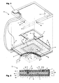
- FIG. 1 shows the Fig. 1 with partial cut in Fig. 2 a soundproof panel in perspective rear view as an exploded view.
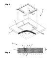
- FIG. 3 and FIG. 4 show this kind of an alternative, exterior frameless soundproofing.
- a prismatic sound insulation panel 1 measuring 60 cm ⁇ 60 cm ⁇ 4 cm has a two-part molded body 2 ⁇ 2a, 2b ⁇ made of translucent, translucent, white, open-cell, sound-absorbing foam of melamine resin (Basotect V3012 or G +) Side surfaces 3 and at the rear side 4 electrically powered lamps 5 ⁇ 5 a, 5 b, 5 c ⁇ are arranged such that the light flows through the front-side molded body 2 a and exits at the front 6.
- the illuminants 5, which are designed both as LED area radiators 5a, LED line radiators 5b and LED spotlights 5c, are electrically connected to a digital control interface 7 arranged on the rear side.
- the illuminating means 5 with the associated groove-shaped recesses 8, an LED surface radiator 5a interspersed with holes 9 and a luminescent layer 10 of thin, transparent Plexiglas are arranged on the rear side, in the depth region of the linear radiator 5b follows.
- the designed as a LED line radiator 5b bulb 5 is mounted on both sides on an inner and on the inside on an outer metal, in cross-section L-shaped mounting frame 11, which forms a forward projecting adhesive element 12, each having a suitable adhesive locking detent opening 13 in the back Shaped body 2b is assigned.
- a light source 5 designed as quasi-tessellated LED line radiator 5b is glued to a thin metal cooling strip 15 and in turn is adhesively frictionally inserted into a slot 16 of the rear-side molded body 2b.
- the molded bodies 2 a, 2 b are covered with a visually translucent covering 14 made of artificial silk comprising the front side 6 and the side surfaces 3.
Landscapes
- Engineering & Computer Science (AREA)
- Architecture (AREA)
- Civil Engineering (AREA)
- Structural Engineering (AREA)
- Physics & Mathematics (AREA)
- Electromagnetism (AREA)
- General Engineering & Computer Science (AREA)
- Arrangement Of Elements, Cooling, Sealing, Or The Like Of Lighting Devices (AREA)
- Building Environments (AREA)
- Soundproofing, Sound Blocking, And Sound Damping (AREA)
Abstract
Description
- Die Erfindung betrifft eine Schalldämmplatte aus Schaumstoff zur Dämpfung des Hörschalls im Innenraumbereich, insbesondere zur zumindest teilweisen Verkleidung von Decken, Raumteilern oder Wänden.
- Eine nach
CH689525A - Der Formkörper besteht üblicherweise vollständig aus einem gesundheitlich unbedenklichen, besonders weichen, offenporigen Schaumstoff hoher Elastizität, bspw. Melaminharz, Polyurethan sowie nach der
DE10084903B4 aus Polyetherpolyurethan, welcher durch seine offenporige Oberfläche gewährleistet, dass Schallwellen nicht als Hall reflektiert werden sondern ungehindert in die Zellstruktur eindringen können und in dieser, durch einen bei Raumtemperatur hohen Verlustfaktor der dynamischen Viskoelastizität, zumindest in Teilbereichen zwischen 16 Hz und 16 kHz des Hörschalls signifikant gedämpft werden. Da ein derartiger Schaumstoff eine extrem geringe Wärmeleitfähigkeit aufweist, dienen die Schalldämmplatten zudem der Wärmedämmung im Innenraumbereich. - Bei zudem vorbekannten LED-Beleuchtungspanelen sind direkt an der Vorderseite angeordnete Leuchtmittel oder Leuchtschichten vorhanden, die zur Beleuchtung und/oder als Motiv dienen, jedoch auch den Hörschall reflektieren.
- Zur Beleuchtung als solches sind geeignete elektrische, mit Niederspannung aus einem geeigneten Netzteil betriebene, stetige Flächenstrahler in Form von organischen Leuchtfolien und Linienstrahler in Form von organischen Leuchtkabeln bekannt, ebenso Leuchtdioden jeder Art (LED) einzeln sowie in Form von quasistetigen LED-Bändern und LED-Arrays. Trotz ihres bekannt hohen Wirkungsgrades wird der Grossteil der zugeführten elektrischen Energie wieder in Form von Wärme abgegeben, wodurch auch diese heiss werden können.
- Die Aufgabe der Erfindung besteht in der Realisierung einer weiteren Nutzung von derartigen Schalldämmplatten. Die Aufgabe wird mit den Merkmalen des Anspruchs 1 gelöst. Vorteilhafte Weiterbildungen ergeben sich aus den Unteransprüchen.
- Im Wesentlichen sind bei einer Schalldämmplatte zur Dämpfung des Hörschalls im Innenraumbereich zumindest teilweise an den Seitenflächen und/oder an der Rückseite elektrisch gespeiste Leuchtmittel derart angeordnet, dass deren Licht zumindest einen lichtdurchlässigen Formkörper aus (vorteilhaft offenporigen) Schaumstoff durchflutet und zumindest teilweise an der Vorderseite austritt.
- Bei der Durchflutung des Schaumstoff-Formkörpers mit Licht wirkt die einzelne Schalldämmplatte zusätzlich als eine Flächenleuchte, welche abhängig von der gewählten Beleuchtungsstärke und Lichtfarbe aktiv zur sichtbaren Raumgestaltung beitragen, die emotional erfahrbare Raumstimmung verändern sowie, bei einer hier angenommenen maximal zulässigen elektrischen Leistung zwischen 20 W und 200 W, zu einer schattenfreien Ausleuchtung beitragen kann.
- Vorteilhaft ist das Leuchtmittel mit einer, optional rückseitig angeordneten sowie als Stecksystem ausgebildeten, digitalen Steuerschnittstelle zur Steuerung der Beleuchtungsstärke und/oder Lichtfarbe verbunden, wodurch mehrere im Raster bzw. in Mosaiken angeordnete sowie über einen Steuerbus verbundene Schalldämmplatten - gleichartig oder in vorwählbaren Mustern - als Grossflächenleuchte ansteuerbar sind, insbesondere direkt über das Stromversorgungsnetz von einem Steuerrechner, welcher direkt als Eingabegerät oder indirekt als über ein optional drahtloses Netzwerk gesteuertes Netzwerkgerät vom Nutzer steuerbar ist.
- Vorteilhaft ist das Leuchtmittel zumindest teilweise als ein Flächenstrahler ausgebildet, optional als ein quasistetiges LED-Array oder eine stetige Leuchtfolie, welche weiter vorteilhaft im Wesentlichen einseitig strahlt, wodurch insbesondere bei einer zweckdienlichen Anordnung auf oder nahe der Rückseite eine gleichmässige Durchflutung des dünnen vorderen Formkörpers erfolgt.
- Vorteilhaft ist das Leuchtmittel zumindest teilweise als Linienstrahler ausgebildet, optional als ein quasistetiges LED-Band oder ein stetiges Leuchtband, welches weiter vorteilhaft im Wesentlichen einseitig strahlt, wodurch insbesondere bei einer zweckdienlichen Anordnung mittig auf oder nahe den Seitenflächen eine randseitige Durchflutung des Formkörpers erfolgt.
- Vorteilhaft ist das Leuchtmittel zumindest teilweise als Punktstrahler ausgebildet, optional als genau eine einzelne LED, mehrere LEDs oder mit einer Vielzahl untereinander verschalteter einzelner Punktstrahler in Form eines quasistetigen LED-Bandes oder LED-Arrays, wodurch bei Massenwaren eine ökonomische Realisierung als Mittelpunktstrahler, seitlicher Eckstrahler, seitlicher und/oder rückseitiger Punktrasterstrahler möglich ist.
- Vorteilhaft weist der Formkörper im Bereich der Leuchtmittel geeignet geformte Aussparungen auf, vorteilhaft Längsbohrungen oder V-förmige Längsnuten, wodurch trotz randseitiger öder eckseitiger Einstrahlung eine weitgehend gleichmässige Lichtdurchflutung erfolgt.
- Vorteilhaft ist rückseitig zumindest des vorderseitigen Formkörpers eine Leuchtschicht aus lichtleitendem Material angeordnet, bspw. aus Glasfaserflies, dünner Plexiglasplatte oder Leuchtfolie, wodurch punktuell oder randseitig eingestrahltes Licht gleichmässig verteilt wird, ohne die Schalldämpfung wesentlich zu beeinträchtigen.
- Vorteilhaft ist die optional bedruckte und eingefräste Leuchtschicht mit Löchern durchsetzt, welche weiter vorteilhaft nach Grösse und Position ideal verteilt sind den Lichtstrom homogenisieren, wodurch ein Schalldurchlass zu optional rückseitigen Formkörpern gewährt ist und tieffrequenter Schall durch die grössere Schaumstoffdicke gedämpft wird.
- Leuchtmittel geringer Abwärme können direkt oder optional mit einer dünnen metallischen Kühlleiste verklebt auf den Formkörper aufgebracht sowie in Schlitze oder Aussparungen des Formkörpers eingebracht werden, vorteilhaft verklebt, wodurch der Herstellungsaufwand minimal ist.
- Vorteilhaft sind die Leuchtmittel auf einem Montagerahmen aus relativ zum Formkörper wärmeleitfähigeren Material wie Metall montiert, wodurch bei Leuchtmitteln höherer Abwärme diese abgeführt und grossflächig über den Montagerahmen verteilt wird. Vorteilhaft weist der Montagerahmen zumindest ein zur Vorderseite hin auskragendes Haftelement auf, dem eine passende haftreibschlüssige Haftöffnung im Formkörper zugeordnet ist, wodurch nach der Montage des Montagerahmens an der Innenraumfläche - der leichte Formkörper nur aufgesteckt werden muss und insbesondere wieder werkzeuglos demontiert bzw. ausgewechselt werden kann. Insbesondere kann ein in der Fläche geschlossen umlaufend ausgebildeter Montagerahmen mit einem vorteilhaft L-förmigen Querschnitt, an welchen sowohl nach innen und/oder nach aussen orientierte Leuchtmittel befestigt sind, mit seinem in der Tiefe nach vorn auskragenden Haftelement in eine umlaufende Haftnut des Formkörpers haftreibschlüssig passend eingreifen. So kann insbesondere der Formkörper einfach erneuert bzw. gegen eine Vielzahl unterschiedlich gestalteter Formkörper ausgewechselt werden.
- Vorteilhaft ist der Formkörper mit einem zumindest die Vorderseite und die Seitenflächen umfassenden, optional wechselbaren, optisch durchscheinenden Bezug aus leichten Materialien wie Kunstseide überzogen, wodurch eine passive Grundfarbe sowie allfällige Motive aufbringbar sind, ohne die Schalldämpfung zu mindern.
- Die Erfindung wird anhand von vorteilhaften Ausführungsbeispielen näher erläutert. Dabei zeigt die
Fig. 1 mit Teilschnitt inFig. 2 eine Schalldämmplatte in perspektivischer Rückansicht als Explosionsdarstellung. DieFig. 3 und Fig. 4 zeigen dieserart eine alternative, aussen rahmenlose Schalldämmplatte. - Nach der
Fig. 1 und Fig. 2 weist eine prismatische Schalldämmplatte 1 der Grösse 60 cm x 60 cm x 4 cm einen zweiteiligen Formkörper 2 {2a, 2b} aus blickdichtem, transluzentem, lichtdurchlässigem, weissem, offenzelligem, schallabsorbierendem Schaumstoff aus Melaminharz (Basotect V3012 bzw. G+) auf, an dessen Seitenflächen 3 und an dessen Rückseite 4 elektrisch gespeiste Leuchtmittel 5 {5a, 5b, 5c} derart angeordnet sind, dass deren Licht den vorderseitigen Formkörper 2a durchflutet und an der Vorderseite 6 austritt. Die sowohl als LED-Flächenstrahler 5a, LED-Linienstrahler 5b und LED-Punktstrahler 5c ausgebildeten Leuchtmittel 5 sind mit einer rückseitig angeordneten digitalen Steuerschnittstelle 7 elektrisch verbunden. An dem vorderseitigen Formkörper 2a ist rückseitig, im Tiefenbereich der als Linienstrahler 5b ausgebildeten Leuchtmittel 5 mit den zugeordneten nutförmigen Aussparungen 8, ein jeweils mit Löchern 9 durchsetzter LED-Flächenstrahler 5a und eine Leuchtschicht 10 aus dünnem, transparentem Plexiglas angeordnet, welcher der rückseitige Formkörper 2b folgt. Das als LED-Linienstrahler 5b ausgebildete Leuchtmittel 5 ist beidseitig auf einem inneren sowie innenseitig auf einem äusseren metallenen, im Querschnitt L-förmigen Montagerahmen 11 montiert, der ein nach vorn auskragendes Haftelement 12 ausbildet, dem jeweils eine passende haftreibschlüssige Haftöffnung 13 im rückseitigen Formkörper 2b zugeordnet ist. Zusätzlich ist ein als quasistetiger LED-Linienstrahler 5b ausgebildetes Leuchtmittel 5 mit einer dünnen metallischen Kühlleiste 15 verklebt und diese wiederum in einen Schlitz 16 des rückseitigen Formkörpers 2b haftreibschlüssig eingebracht. Die Formkörper 2a, 2b sind mit einem, die Vorderseite 6 und die Seitenflächen 3 umfassenden, optisch durchscheinenden Bezug 14 aus Kunstseide überzogen. - Dazu im Unterschied sind entsprechend der
Fig. 3 und Fig. 4 bei einer alternativen Schalldämmplatte 1' nur die als quasistetige LED-Linienstrahler 5b ausgebildeten Leuchtmittel 5 beidseitig an einem inneren Montagerahmen 11 angebracht und an dessen nach vorn auskragendem Haftelement 12 der einteilige Formkörper 2 mittels der Haftöffnung 13 haftreibschlüssig befestigt. Die Haftöffnung 13 weist im Tiefenbereich, den LED-Linienstrahlern 5b zugeordnete, nutförmige Aussparungen 8 auf.
Claims (10)
- Schalldämmplatte zur Dämpfung des Hörschalls im Innenraumbereich mit zumindest einem Formkörper (2, 2a, 2b) aus Schaumstoff, dadurch gekennzeichnet, dass zumindest teilweise an den Seitenflächen (3) und/oder an der Rückseite (4) des Formkörpers (2, 2a, 2b) zumindest ein elektrisch gespeistes Leuchtmittel (5, 5a, 5b, 5c) derart angeordnet ist, dass dessen Licht zumindest einen lichtdurchlässigen Formkörper (2, 2a) durchflutet und zumindest teilweise an der Vorderseite (6) austritt.
- Schalldämmplatte nach Anspruch 1, dadurch gekennzeichnet, dass das Leuchtmittel (5, 5a, 5b, 5c) mit einer digitalen Steuerschnittstelle (7) verbunden ist.
- Schalldämmplatte nach Anspruch 1 oder 2, dadurch gekennzeichnet, dass das Leuchtmittel (5, 5a, 5b, 5c) zumindest teilweise als ein Flächenstrahler (5a), Linienstrahler (5b) und/oder Punktstrahler (5c) ausgebildet ist.
- Schalldämmplatte nach einem der Ansprüche 1 bis 3, dadurch gekennzeichnet, dass der Formkörper (2, 2a, 2b) im Bereich des Leuchtmittels (5, 5a, 5b, 5c) Aussparungen (8) aufweist.
- Schalldämmplatte nach einem der Ansprüche 1 bis 4, dadurch gekennzeichnet, dass rückseitig zumindest des vorderseitigen Formkörpers (2, 2a) eine Leuchtschicht (10) aus lichtleitendem Material angeordnet ist.
- Schalldämmplatte nach Anspruch 5, dadurch gekennzeichnet, dass die Leuchtschicht (10) mit Löchern (9) durchsetzt ist.
- Schalldämmplatte nach einem der Ansprüche 1 bis 6, dadurch gekennzeichnet, dass das Leuchtmittel (5, 5a, 5b, 5c), direkt oder mit einer dünnen metallischen Kühlleiste (15) verklebt, mit dem Formkörper (2, 2a, 2b) verbunden ist.
- Schalldämmplatte nach einem der Ansprüche 1 bis 7, dadurch gekennzeichnet, dass das Leuchtmittel (5, 5a, 5b, 5c) auf einem Montagerahmen (11) montiert ist.
- Schalldämmplatte nach Anspruch 8, dadurch gekennzeichnet, dass der Montagerahmen (11) zumindest ein zur Vorderseite hin auskragendes Haftelement (12) aufweist, dem eine passende haftreibschlüssige Haftöffnung (13) im Formkörper (2, 2a, 2b) zugeordnet ist.
- Schalldämmplatte nach einem der Ansprüche 1 bis 9, dadurch gekennzeichnet, dass der Formkörper (2, 2a, 2b) mit einem, zumindest die Vorderseite (6) und die Seitenflächen (3) umfassenden, optisch durchscheinenden Bezug (14) überzogen ist.
Applications Claiming Priority (1)
| Application Number | Priority Date | Filing Date | Title |
|---|---|---|---|
| CH01024/13A CH708188A2 (de) | 2013-05-29 | 2013-05-29 | Schalldämmplatte mit Leuchtmittel. |
Publications (2)
| Publication Number | Publication Date |
|---|---|
| EP2813630A2 true EP2813630A2 (de) | 2014-12-17 |
| EP2813630A3 EP2813630A3 (de) | 2014-12-24 |
Family
ID=52014633
Family Applications (1)
| Application Number | Title | Priority Date | Filing Date |
|---|---|---|---|
| EP20140001894 Withdrawn EP2813630A3 (de) | 2013-05-29 | 2014-05-29 | Beleuchteter Akustikabsorber |
Country Status (2)
| Country | Link |
|---|---|
| EP (1) | EP2813630A3 (de) |
| CH (1) | CH708188A2 (de) |
Cited By (15)
| Publication number | Priority date | Publication date | Assignee | Title |
|---|---|---|---|---|
| DE102014112556A1 (de) * | 2014-09-01 | 2016-03-03 | Technische Universität Dresden | Akustisch wirksames Raumteilsystem |
| WO2019134829A1 (en) * | 2018-01-02 | 2019-07-11 | Signify Holding B.V. | Lighting module, kit and panel |
| WO2019214854A1 (en) * | 2018-05-07 | 2019-11-14 | Eaton Intelligent Power Limited | Suspended lightguide luminaire with linear sound baffles |
| USD869733S1 (en) | 2018-05-07 | 2019-12-10 | Eaton Intelligent Power Limited | Suspended lightguide luminaire with linear sound baffles |
| US10876290B2 (en) | 2017-05-19 | 2020-12-29 | 3Form, Llc | Felt baffle with snap ends |
| USD915634S1 (en) | 2015-05-28 | 2021-04-06 | 3Form, Llc | Tall baffle |
| USD915633S1 (en) | 2013-11-15 | 2021-04-06 | 3Form, Llc | Baffle |
| USD915631S1 (en) | 2014-11-14 | 2021-04-06 | 3Form, Llc | Baffle with closed ends |
| USD915632S1 (en) | 2013-11-15 | 2021-04-06 | 3Form, Llc | Baffle with reduced height |
| USD917079S1 (en) | 2013-11-15 | 2021-04-20 | 3Form, Llc | Thin baffle |
| USD959030S1 (en) | 2013-11-15 | 2022-07-26 | 3Form, Llc | Baffle with slit end |
| USD1054617S1 (en) | 2022-08-22 | 2024-12-17 | 3Form, Llc | T-shaped light fixture |
| USD1062002S1 (en) | 2022-08-22 | 2025-02-11 | 3Form, Llc | X-shaped light fixture |
| USD1062003S1 (en) | 2022-08-22 | 2025-02-11 | 3Form, Llc | Hexagonal-shaped light fixture |
| USD1062004S1 (en) | 2022-08-22 | 2025-02-11 | 3Form, Llc | Y-shaped light fixture |
Families Citing this family (4)
| Publication number | Priority date | Publication date | Assignee | Title |
|---|---|---|---|---|
| FI11839U1 (fi) | 2017-05-24 | 2017-10-24 | Aurinkopuro Oy | Akustinen valoelementti |
| EP3587691B1 (de) * | 2018-06-25 | 2023-08-02 | LTS Licht & Leuchten GmbH | Schalldaempfende vorrichtung |
| PL3769971T3 (pl) * | 2019-07-23 | 2025-02-17 | Visound Acustica Sa | Warstwa dostrajająca dźwięk i panel do akustycznej adaptacji pomieszczenia |
| EP4341603B1 (de) * | 2021-05-18 | 2025-07-09 | Signify Holding B.V. | Akustische beleuchtungsvorrichtung |
Family Cites Families (4)
| Publication number | Priority date | Publication date | Assignee | Title |
|---|---|---|---|---|
| GB2397160B (en) * | 2003-01-07 | 2006-02-01 | Daer Lighting Ltd | Lighting |
| DE202008008896U1 (de) * | 2008-10-27 | 2010-03-18 | Pinta Acoustic Gmbh | Schaumstoffteil sowie hängend befestigter Schallabsorber |
| DE102011101913A1 (de) * | 2011-05-18 | 2012-11-22 | Bosig Gmbh | Schallabsorbierende Leuchte |
| DE202011050319U1 (de) * | 2011-05-31 | 2011-11-28 | Mediplan Helm Ohg | Lichtführungsplatte und Lampe |
-
2013
- 2013-05-29 CH CH01024/13A patent/CH708188A2/de not_active Application Discontinuation
-
2014
- 2014-05-29 EP EP20140001894 patent/EP2813630A3/de not_active Withdrawn
Cited By (23)
| Publication number | Priority date | Publication date | Assignee | Title |
|---|---|---|---|---|
| USD959030S1 (en) | 2013-11-15 | 2022-07-26 | 3Form, Llc | Baffle with slit end |
| USD917079S1 (en) | 2013-11-15 | 2021-04-20 | 3Form, Llc | Thin baffle |
| USD916348S1 (en) | 2013-11-15 | 2021-04-13 | 3Form, Llc | Light-weight lighting fixture |
| USD915632S1 (en) | 2013-11-15 | 2021-04-06 | 3Form, Llc | Baffle with reduced height |
| USD915633S1 (en) | 2013-11-15 | 2021-04-06 | 3Form, Llc | Baffle |
| DE102014112556A1 (de) * | 2014-09-01 | 2016-03-03 | Technische Universität Dresden | Akustisch wirksames Raumteilsystem |
| EP2990559A3 (de) * | 2014-09-01 | 2016-06-22 | Technische Universität Dresden | Akustisch wirksames raumteilsystem |
| USD915631S1 (en) | 2014-11-14 | 2021-04-06 | 3Form, Llc | Baffle with closed ends |
| USD915634S1 (en) | 2015-05-28 | 2021-04-06 | 3Form, Llc | Tall baffle |
| US10889987B2 (en) | 2017-05-19 | 2021-01-12 | 3Form, Llc | Felt baffle with snap ends |
| US10876290B2 (en) | 2017-05-19 | 2020-12-29 | 3Form, Llc | Felt baffle with snap ends |
| US11320139B2 (en) | 2018-01-02 | 2022-05-03 | Signify Holding B.V. | Lighting module, kit and panel |
| WO2019134829A1 (en) * | 2018-01-02 | 2019-07-11 | Signify Holding B.V. | Lighting module, kit and panel |
| WO2019214854A1 (en) * | 2018-05-07 | 2019-11-14 | Eaton Intelligent Power Limited | Suspended lightguide luminaire with linear sound baffles |
| USD869733S1 (en) | 2018-05-07 | 2019-12-10 | Eaton Intelligent Power Limited | Suspended lightguide luminaire with linear sound baffles |
| US10920970B2 (en) | 2018-05-07 | 2021-02-16 | Signify Holding B.V. | Suspended lightguide luminaire with linear sound baffles |
| US10598355B2 (en) | 2018-05-07 | 2020-03-24 | Eaton Intelligent Power Limited | Suspended lightguide luminaire with linear sound baffles |
| CN112313444A (zh) * | 2018-05-07 | 2021-02-02 | 昕诺飞控股有限公司 | 具有线性声音隔板的悬挂式光导照明装置 |
| CN112313444B (zh) * | 2018-05-07 | 2022-09-13 | 昕诺飞控股有限公司 | 具有线性声音隔板的悬挂式光导照明装置 |
| USD1054617S1 (en) | 2022-08-22 | 2024-12-17 | 3Form, Llc | T-shaped light fixture |
| USD1062002S1 (en) | 2022-08-22 | 2025-02-11 | 3Form, Llc | X-shaped light fixture |
| USD1062003S1 (en) | 2022-08-22 | 2025-02-11 | 3Form, Llc | Hexagonal-shaped light fixture |
| USD1062004S1 (en) | 2022-08-22 | 2025-02-11 | 3Form, Llc | Y-shaped light fixture |
Also Published As
| Publication number | Publication date |
|---|---|
| CH708188A2 (de) | 2014-12-15 |
| EP2813630A3 (de) | 2014-12-24 |
Similar Documents
| Publication | Publication Date | Title |
|---|---|---|
| CH708188A2 (de) | Schalldämmplatte mit Leuchtmittel. | |
| US9194124B2 (en) | Acoustic light panel | |
| CA2805234C (en) | Light panel and method for producing the light panel | |
| EP2935984B1 (de) | Schallabsorbierende leuchttafel und modulares oberflächensystem | |
| US20140226360A1 (en) | Light-emitting panel with transparent cellular support panel | |
| WO2002052192A1 (de) | Sandwichartiges plattenelement | |
| DE202011000426U1 (de) | Lichtkanal mit Wärmeableitung sowie Lichtkanalanordnung | |
| EP1425990A1 (de) | Einrichtungselement mit selbstleuchtenden Sichtflächen und Verfahren zur Herstellung | |
| EP2765354A1 (de) | Leuchte mit Lichtleitscheibe | |
| EP2330344B1 (de) | Veränderbare Leuchtvorrichtung | |
| EP2388510A2 (de) | Beleuchtungselement | |
| CN201772327U (zh) | 一种led面板灯 | |
| AT510641B1 (de) | Schallabsorbierende leuchte | |
| EP1361316B1 (de) | Bauplatte für Decken, Wände oder Böden | |
| WO2012156060A1 (de) | Schallabsorbierende leuchte | |
| EP2529259B1 (de) | Beleuchtungskörper mit einer lichtquelle und einem optischen diffusor | |
| AT517621B1 (de) | Vorrichtung für die kombinierte Abgabe von Wärmestrahlung und Licht | |
| DE202011103747U1 (de) | Beleuchtete Möbelfronten | |
| DE202005013117U1 (de) | Wärmebehandlungskabine | |
| KR101387382B1 (ko) | 필름 및 이를 포함하는 조명식 마감재 | |
| CN202915216U (zh) | 可任意排列组合的车灯结构 | |
| DE202017100618U1 (de) | Schalldämmendes Lichtsystem | |
| DE202017103001U1 (de) | Beleuchtete Magnettafelanordnung | |
| DE202004005078U1 (de) | Einbauleuchten für Glasbausteine | |
| DE202019103165U1 (de) | Tisch mit einer beleuchtbaren Tischplatte |
Legal Events
| Date | Code | Title | Description |
|---|---|---|---|
| PUAL | Search report despatched |
Free format text: ORIGINAL CODE: 0009013 |
|
| 17P | Request for examination filed |
Effective date: 20140529 |
|
| AK | Designated contracting states |
Kind code of ref document: A2 Designated state(s): AL AT BE BG CH CY CZ DE DK EE ES FI FR GB GR HR HU IE IS IT LI LT LU LV MC MK MT NL NO PL PT RO RS SE SI SK SM TR |
|
| AX | Request for extension of the european patent |
Extension state: BA ME |
|
| PUAI | Public reference made under article 153(3) epc to a published international application that has entered the european phase |
Free format text: ORIGINAL CODE: 0009012 |
|
| AK | Designated contracting states |
Kind code of ref document: A3 Designated state(s): AL AT BE BG CH CY CZ DE DK EE ES FI FR GB GR HR HU IE IS IT LI LT LU LV MC MK MT NL NO PL PT RO RS SE SI SK SM TR |
|
| AX | Request for extension of the european patent |
Extension state: BA ME |
|
| RIC1 | Information provided on ipc code assigned before grant |
Ipc: E04B 9/04 20060101ALN20141119BHEP Ipc: E04B 9/34 20060101ALN20141119BHEP Ipc: E04B 1/86 20060101AFI20141119BHEP Ipc: E04B 9/32 20060101ALN20141119BHEP |
|
| STAA | Information on the status of an ep patent application or granted ep patent |
Free format text: STATUS: THE APPLICATION IS DEEMED TO BE WITHDRAWN |
|
| 18D | Application deemed to be withdrawn |
Effective date: 20150625 |