EP2824057B1 - Élévation d'un segment de tour - Google Patents
Élévation d'un segment de tour Download PDFInfo
- Publication number
- EP2824057B1 EP2824057B1 EP13176120.7A EP13176120A EP2824057B1 EP 2824057 B1 EP2824057 B1 EP 2824057B1 EP 13176120 A EP13176120 A EP 13176120A EP 2824057 B1 EP2824057 B1 EP 2824057B1
- Authority
- EP
- European Patent Office
- Prior art keywords
- holding members
- raising device
- holding
- tower segment
- raising
- Prior art date
- Legal status (The legal status is an assumption and is not a legal conclusion. Google has not performed a legal analysis and makes no representation as to the accuracy of the status listed.)
- Active
Links
Images




Classifications
-
- B—PERFORMING OPERATIONS; TRANSPORTING
- B66—HOISTING; LIFTING; HAULING
- B66C—CRANES; LOAD-ENGAGING ELEMENTS OR DEVICES FOR CRANES, CAPSTANS, WINCHES, OR TACKLES
- B66C1/00—Load-engaging elements or devices attached to lifting or lowering gear of cranes or adapted for connection therewith for transmitting lifting forces to articles or groups of articles
- B66C1/10—Load-engaging elements or devices attached to lifting or lowering gear of cranes or adapted for connection therewith for transmitting lifting forces to articles or groups of articles by mechanical means
- B66C1/108—Load-engaging elements or devices attached to lifting or lowering gear of cranes or adapted for connection therewith for transmitting lifting forces to articles or groups of articles by mechanical means for lifting parts of wind turbines
-
- B—PERFORMING OPERATIONS; TRANSPORTING
- B66—HOISTING; LIFTING; HAULING
- B66C—CRANES; LOAD-ENGAGING ELEMENTS OR DEVICES FOR CRANES, CAPSTANS, WINCHES, OR TACKLES
- B66C1/00—Load-engaging elements or devices attached to lifting or lowering gear of cranes or adapted for connection therewith for transmitting lifting forces to articles or groups of articles
- B66C1/10—Load-engaging elements or devices attached to lifting or lowering gear of cranes or adapted for connection therewith for transmitting lifting forces to articles or groups of articles by mechanical means
- B66C1/42—Gripping members engaging only the external or internal surfaces of the articles
- B66C1/44—Gripping members engaging only the external or internal surfaces of the articles and applying frictional forces
- B66C1/442—Gripping members engaging only the external or internal surfaces of the articles and applying frictional forces actuated by lifting force
-
- B—PERFORMING OPERATIONS; TRANSPORTING
- B66—HOISTING; LIFTING; HAULING
- B66C—CRANES; LOAD-ENGAGING ELEMENTS OR DEVICES FOR CRANES, CAPSTANS, WINCHES, OR TACKLES
- B66C1/00—Load-engaging elements or devices attached to lifting or lowering gear of cranes or adapted for connection therewith for transmitting lifting forces to articles or groups of articles
- B66C1/10—Load-engaging elements or devices attached to lifting or lowering gear of cranes or adapted for connection therewith for transmitting lifting forces to articles or groups of articles by mechanical means
- B66C1/62—Load-engaging elements or devices attached to lifting or lowering gear of cranes or adapted for connection therewith for transmitting lifting forces to articles or groups of articles by mechanical means comprising article-engaging members of a shape complementary to that of the articles to be handled
-
- E—FIXED CONSTRUCTIONS
- E04—BUILDING
- E04H—BUILDINGS OR LIKE STRUCTURES FOR PARTICULAR PURPOSES; SWIMMING OR SPLASH BATHS OR POOLS; MASTS; FENCING; TENTS OR CANOPIES, IN GENERAL
- E04H12/00—Towers; Masts or poles; Chimney stacks; Water-towers; Methods of erecting such structures
- E04H12/34—Arrangements for erecting or lowering towers, masts, poles, chimney stacks, or the like
- E04H12/342—Arrangements for stacking tower sections on top of each other
-
- F—MECHANICAL ENGINEERING; LIGHTING; HEATING; WEAPONS; BLASTING
- F03—MACHINES OR ENGINES FOR LIQUIDS; WIND, SPRING, OR WEIGHT MOTORS; PRODUCING MECHANICAL POWER OR A REACTIVE PROPULSIVE THRUST, NOT OTHERWISE PROVIDED FOR
- F03D—WIND MOTORS
- F03D13/00—Assembly, mounting or commissioning of wind motors; Arrangements specially adapted for transporting wind motor components
- F03D13/10—Assembly of wind motors; Arrangements for erecting wind motors
-
- F—MECHANICAL ENGINEERING; LIGHTING; HEATING; WEAPONS; BLASTING
- F05—INDEXING SCHEMES RELATING TO ENGINES OR PUMPS IN VARIOUS SUBCLASSES OF CLASSES F01-F04
- F05B—INDEXING SCHEME RELATING TO WIND, SPRING, WEIGHT, INERTIA OR LIKE MOTORS, TO MACHINES OR ENGINES FOR LIQUIDS COVERED BY SUBCLASSES F03B, F03D AND F03G
- F05B2230/00—Manufacture
- F05B2230/60—Assembly methods
- F05B2230/61—Assembly methods using auxiliary equipment for lifting or holding
-
- F—MECHANICAL ENGINEERING; LIGHTING; HEATING; WEAPONS; BLASTING
- F05—INDEXING SCHEMES RELATING TO ENGINES OR PUMPS IN VARIOUS SUBCLASSES OF CLASSES F01-F04
- F05B—INDEXING SCHEME RELATING TO WIND, SPRING, WEIGHT, INERTIA OR LIKE MOTORS, TO MACHINES OR ENGINES FOR LIQUIDS COVERED BY SUBCLASSES F03B, F03D AND F03G
- F05B2240/00—Components
- F05B2240/90—Mounting on supporting structures or systems
- F05B2240/91—Mounting on supporting structures or systems on a stationary structure
- F05B2240/912—Mounting on supporting structures or systems on a stationary structure on a tower
-
- Y—GENERAL TAGGING OF NEW TECHNOLOGICAL DEVELOPMENTS; GENERAL TAGGING OF CROSS-SECTIONAL TECHNOLOGIES SPANNING OVER SEVERAL SECTIONS OF THE IPC; TECHNICAL SUBJECTS COVERED BY FORMER USPC CROSS-REFERENCE ART COLLECTIONS [XRACs] AND DIGESTS
- Y02—TECHNOLOGIES OR APPLICATIONS FOR MITIGATION OR ADAPTATION AGAINST CLIMATE CHANGE
- Y02E—REDUCTION OF GREENHOUSE GAS [GHG] EMISSIONS, RELATED TO ENERGY GENERATION, TRANSMISSION OR DISTRIBUTION
- Y02E10/00—Energy generation through renewable energy sources
- Y02E10/70—Wind energy
- Y02E10/72—Wind turbines with rotation axis in wind direction
-
- Y—GENERAL TAGGING OF NEW TECHNOLOGICAL DEVELOPMENTS; GENERAL TAGGING OF CROSS-SECTIONAL TECHNOLOGIES SPANNING OVER SEVERAL SECTIONS OF THE IPC; TECHNICAL SUBJECTS COVERED BY FORMER USPC CROSS-REFERENCE ART COLLECTIONS [XRACs] AND DIGESTS
- Y02—TECHNOLOGIES OR APPLICATIONS FOR MITIGATION OR ADAPTATION AGAINST CLIMATE CHANGE
- Y02E—REDUCTION OF GREENHOUSE GAS [GHG] EMISSIONS, RELATED TO ENERGY GENERATION, TRANSMISSION OR DISTRIBUTION
- Y02E10/00—Energy generation through renewable energy sources
- Y02E10/70—Wind energy
- Y02E10/728—Onshore wind turbines
Definitions
- the present invention concerns a raising device realized to be connected to a tower segment of a wind turbine. It also concerns a method of equipping a tower segment of a wind turbine for transport.
- Wind turbines comprise a tower and a nacelle placed on top of that tower, whereby the nacelle is equipped with a rotor which rotates due to the impact of wind. In the nacelle, the rotational movement of the rotor is used to generate electric power.
- Large wind turbine towers often comprise a number of tower segments, e. g. made of steel, which when assembled together form the complete wind turbine tower.
- the standard state of the art is to assemble a wind turbine tower by attaching a number of brackets to an end flange of a tower segment and to connect a number of wires to these brackets.
- These wires are connected to a crane or to a similar raising machine and the tower segment is raised and transported to the site of assembly where it is connected either to a foundation of the wind turbine tower or to a lower tower segment to which the tower segment in question is then attached by e. g. bolting.
- the wires have to be disconnected from the tower segment, as well as the brackets, and the same procedure must be re-done for each tower segment until the complete wind turbine tower is established.
- EP 2 402 278 B1 describes an arrangement for raising a tower segment of a wind turbine. It comprises a beam and a cross beam along both of which holding members are attached which holding members can engage with a flange of a tower segment when moved along the beam and cross-beam. The holding members are moved manually or by a motor into a desired operating position at which they can engage with a counter-shape of the tower segment.
- an improved one in comparison with the above-mentioned state of the art.
- improvement is realized by providing a raising device the use of which is less time-consuming than that of the state of the art.
- a raising device of the kind mentioned in the introductory paragraph comprises a connection member to a raising machine and a plurality of holding members positioned at predefined distances from each other and orientated to be movable in radial locking directions which locking directions are such that the holding members when moved into a locking position at a predefined engagement position of the tower segment engage with a counter-shape of the tower segment, whereby the holding members are automatically tiltable and/or shiftable into the locking position by a movement mechanism, whereby the holding members are mechanically interconnected via the movement mechanism with the connection member via a number of hinges such that upon pulling the connection member upwards, the holding members automatically tilt and/or shift into the locking position unless blocked.
- connection of the raising device to the tower segment is preferably carried out at the top of such tower segment.
- the top of such tower segment is that essentially round opening of the tower segment which is to face upwards when assembled in an upright position on the assembly site.
- the tower segment can be raised by means of the raising device in such upright position, i.e. in the same orientation in which it is to be assembled eventually at the assembly site.
- connection member may for instance comprise a hook or an eye which can engage with a corresponding eye or hook from the raising machine.
- the raising machine may for instance be a crane with a wire to which the connection member can be connected.
- the expression "tower segment” refers both to a segment of a wind turbine tower which - together with other such segments - is part of the complete wind turbine tower but also may refer to a complete wind turbine tower.
- a complete tower be raised in one piece (i.e. in an already assembled state in which segments of the tower have been connected to form the complete tower) in the context of the invention.
- the raising device according to the invention makes such raising possible because it can be built stable enough to carry the complete weight of such complete tower at one time. This would not be the case with a the above-mentioned raising method with brackets and wires: several brackets would be necessary to achieve an overall enough stability of the connection of the tower segment to the raising device during transport.
- the sufficiently stable device according to the invention provides for a solution in which an entire wind turbine tower can be raised as one piece. In fact, even under conditions of transport of the wind turbine tower in one piece, with the raising device according to the invention it is possible to reduce the size and weight of the upper flanges if they are to be used as the couter-shape.
- such transport in one piece has the advantage that assembly times at the assembly site can be reduced to an absolute minimum.
- the entire wind turbine tower can already be transported to the assembly site in one piece and then simply be raised and transported from a means of transport such as a vessel to the assembly site where it is to be installed. Assembly time on that assembly site is thus dedicated wholly to the processes of raising, transport and installation of the wind turbine tower on a foundation.
- the raising device comprises a plurality of holding members positioned at predefined distances from each other. These predefined distances and thus corresponding predefined positions of the holding members correspond with the position of the counter-shape of the tower segment to which the raising device is to be connected. That implies that, unlike in the state of the art mentioned above, the holding members are not positioned anywhere and can then be brought into a desired operating position manually or by means of a motor. Instead, the holding members are generally situated in that desired operating position and need not be moved there.
- an "operating position” means such position in which the holding member can be connected to (or disconnected from) the counter-shape of the tower segment by a pre-defined movement, namely a movement from an open position into a locking position and reverse.
- the open position and the locking position of the holding member are also clearly defined and each holding member is mechanically limited in its movement so that it can only move between those two positions (i.e. between the open position and the locking position).
- each of the holding members Corresponding to the open position and the locking position of each of the holding members is its locking direction and - reverse - its unlocking direction (i.e. the counter direction of the locking direction).
- Both the locking direction and unlocking direction are radial, i.e. along a straight line from the centre point of the (essentially tubular) tower segment to the shell of the tower segment in a section of the tower segment perpendicular to its longitudinal tubular extension. That means that the locking direction is either towards that centre point or away from it and that the unlocking direction is exactly opposite.
- the raising device may comprises three holding members aligned at equal distances along an outer or inner circumference of a tower segment to which they are to be connected.
- each of the holding members can be connected at a predefined position to a holding beam at essentially one end of the holding beam whereas the other end of the holding beam is connected to the corresponding ends of the other holding beams.
- the holding members are automatically tiltable and/or shiftable into their locking position by means of a movement mechanism. That implies that upon activating the movement mechanism the holding members are automatically tilted and/or shifted from the open position into the locking position or vice versa.
- Automatically tilting or shifting preferably implies a purely mechanical movement rather than one induced by manual effort and/or motor power transmission and/or hydraulic / pneumatic power transmission.
- a support by a motor or a hydraulic system is principally feasible.
- the movement mechanism connects the holding members to the connection member of the raising device so that a particular movement of the connection member automatically produces the tilting and/or shifting movement of the holding members unless such movement is intentionally blocked.
- the term "holding member” refers to such a mechanical holding device that is movable in and/or against the locking direction.
- the raising device may also comprise other, non-movable members with a holding function and design which may for instance be used as a counterpart of a holding member.
- one such non-movable member may engage with the counter-shape of the tower segment at a first position, for instance by transferring the non-movable member below the counter-shape by means of form fit, i.e. by positioning the complete raising device with respect to the tower segment such that the non-movable member is engaged with the counter-shape.
- the holding members are moved into their locking positions at a second position (which functions as a counter position to the first position) so that the holding members in their locking positions together with the non-movable members provide a firm hold of the tower segment.
- the invention also concerns a tower segment of a wind turbine equipped with a raising device according to the invention.
- a method of the above-mentioned kind comprises the steps of
- this method further comprises a raising step in which the raising device is raised by means of the raising machine.
- This step takes the equipment method further so that the method then constitutes a raising method or a method of transport rather than just a method of equipping the tower segment.
- At least one holding member comprises a claw (which can also be considered to be a gripper).
- a claw can engage with the counter-shape of the tower segment, for instance by going partially underneath and/or around the counter-shape.
- the counter-shape of the tower segment comprises an inner or outer connection flange to another tower segment and/or towards the nacelle parts of the wind turbine. A claw can thus be tilted or shifted underneath the connection flange and hold it with ease.
- the raising device may comprise three holding members. However, it is principally possible that it only comprises two holding members. It has been found particularly advantageous that the number of holding members is an even number and that the holding members are arranged in pairs of corresponding holding members. In this context, it is preferred that at least two corresponding holding members are aligned along a straight line. This line is preferably a radial line. In particular, these corresponding holding members can be realized and positioned and aligned such that their locking directions are counter directions.
- first holding member is towards the centre point of the tower section and the second, corresponding, holding member is positioned at the opposite side of the centre point of the tower section (with respect to the first holding member) and its locking direction is also towards the centre point of the tower section. Therefore, the second holding member's locking direction is the counter direction of the first holding member's locking direction.
- the tower segment is then held in between the two corresponding holding members which exert a holding force towards the inner side of the tower segment.
- both corresponding holding members can also be orientated in the opposite locking directions, i.e. facing away from the centre point of the tower segment, in which case they exert a holding force towards the outside of the tower segment.
- the first such described embodiment is particularly useful if an outside flange is used as the counter-shape of the tower segment, whereas the second such described embodiment is particularly useful if an inside flange is used as the counter-shape of the tower segment.
- the (preferably straight) beam thus serves as a holding structure for the two corresponding holding members and constitutes the straight line along which the holding members are both aligned.
- the raising device according to the invention comprises (at least) two pairs of corresponding holding members.
- a preferred embodiment of the raising device according to the invention is characterized by a first pair of corresponding holding members being connected to a first common holding beam and a second pair of corresponding holding members being connected to a second common holding beam.
- This second holding beam is preferably realized as a cross-beam of the first holding beam, whereby it is particularly preferred that the cross-beam is orientated essentially perpendicularly to the first holding beam, which makes the construction of the raising device particularly stable.
- the raising device can be positioned such that the point where the first holding beam and the second holding beam are interconnected can essentially be positioned at the above-mentioned centre point of the tower section and that from this centre point the holding members can be arranged essentially equidistantly along the (inner or outer) circumference of the tower section.
- This embodiment can be further enhanced by interconnecting the first holding beam and the second holding beam by a number of diagonal connections such as interconnecting beams, ropes or the like. Such diagonal (inter)connections can further stabilize the raising device so that is can carry even larger loads without the danger of getting twisted or worn.
- the holding members are fixedly installed, i.e. permanently fixed at the predefined distance. This is in particular so if complete towers are to be raised as one by the raising device because then the same width of the tower (segment) always applies for wind turbines of the same make of wind turbine: such tower must always carry a nacelle of a particular size, which depends on the nominal power output of the wind turbine. That width currently varies between about 3000mm and 4500mm.
- a 3,6 MW wind turbine of the applicant has a width of 3128mm and a 6 MW wind turbine a width of 4145mm.
- a change of position of the holding members is not necessary in case one decides to always raise towers of the same make of wind turbines so that instead a more stable, namely fixed, position of the holding members is possible and highly preferred.
- the orientation of the holding members i.e. their designated locking direction could be changed (for instance to be able to engage both with inner and outer flanges of tower segments), but again, in particular in the above-mentioned context of complete towers to be raised, it is preferred that the holding members are fixed also with respect to their orientation.
- the holding members are mechanically interconnected via the movement mechanism with the connection member via a number of hinges such that upon pulling the connection member upwards, the holding members automatically tilt and/or shift into the locking position unless blocked.
- This highly automatized mechanism provides for a safe and very easy locking procedure which thus saves time, effort and expenditure.
- the holding members are realized, i.e. sized, mechanically designed and located, to engage with an upper (inner and/or outer) flange of the tower segment along its (inner and/or outer) circumference.
- This upper flange thus comprises (preferably constitutes) the counter-shape for the holding members.
- Such flanges have proven to be stable enough to withstand all raising forces, which means they can clearly carry the complete weight even of a complete tower. Such also applies for towers of today's sizes and weights, e.g. for 90 metre high steel towers weighing about 300 tons.
- the raising device according to the invention further comprises a blocking mechanism realized to block a movement of the holding members into and/or out of the locking position. That means that once the blocking mechanism is activated, the holding members will essentially remain in their open or locked position. If the holding members are thus in their locking position they cannot be unlocked until the blocking mechanism is deactivated. This prevents the raising device from sudden failure of the locking function of the holding members, for instance due to weather conditions or other negative impacts on the tower segment in a raised position.
- the blocking mechanism is a means of how to effectively prevent the tower segment from uncontrolledly falling down while being raised by means of the raising device.
- such blocking mechanism can comprise a pin which engages with a recess of a movable element of the raising device (i.e. in particular of the movement mechanism) which movable element is connected to at least one of, preferably all of the holding members in order to block a movement of that / the holding member(s).
- the pin can easily be inserted manually into the recess once the holding member(s) has / have reached a desired position. The same way, the pin can be extracted from the recess once a different position (and thus a change of position) of the holding member(s) is desired.
- the invention can further be enhanced by the raising device also comprising a cover realized to cover an open part of the tower segment, i.e. an upper opening of the tower segment facing upwards when the tower segment is positioned in the designated position of assembly in which a nacelle can be placed on the top of the tower.
- a cover realized to cover an open part of the tower segment, i.e. an upper opening of the tower segment facing upwards when the tower segment is positioned in the designated position of assembly in which a nacelle can be placed on the top of the tower.
- Such cover can serve to shield the inside of the tower segment from influences from above, in particular rain or snow.
- the cover can be loosely connected to the raising device, for instance when the cover is installed on the tower segment. In such case, the cover can be installed on the tower segment first and then the raising device can be connected to both the tower segment and the cover. Alternatively, the cover and the raising device can be assembled (i.e. interconnected) and then connected to the tower segment together.
- the cover comprises at least one opening realized as a service opening for staff and/or as a through-hole for at least one of the holding members.
- a service opening for instance a hatch which can be closed by a cover when no staff wants to pass can permit staff from the inner side of the tower segment to the outside on top of the tower segment (or reverse), for instance in order to permit assembly work in these locations.
- a through-hole is preferably sized such that it permits the passage of the corresponding holding member. It may be sized and realized such that it is essentially in contact with the holding member (or a connection of the holding member to other parts of the raising device) so that essentially no rain or snow can pass through the through-hole. I may also be sized slightly larger to permit easier passage of the holding member (or a connection of the holding member to other parts of the raising device).
- Fig. 1 shows a raising device 1 for raising a tower section (not shown) of a wind turbine.
- the raising device 1 comprises a connection member 3 realized as an eye 3 which is attached via a first hinge 5 to four connection shapes 28.
- connection shapes 28 there is each hingedly attached via a second hinge 9 a connection beam 27.
- the connection beams 27 are thus connected essentially at their first end via the second hinges 9 to the connection shapes 28 and at their second ends to third hinges 11 to holding members 19a, 19b, 19c, 19d (the two latter being obscured in the figure due to the perspective view) realized as claws 19a, 19b, 19c, 19d.
- the holding members 19a, 19b, 19c, 19d are realized as two pairs of corresponding holding members 19a, 19b, 19c, 19d, namely a first pair of corresponding holding members 19c, 19d is aligned along a first holding beam 21a and a second pair of corresponding holding members 19a, 19b is aligned along a second holding beam 21b.
- the raising device 1 thus further comprises a first holding beam 21a and a second holding beam 21b which is a perpendicularly positioned cross-beam to the first holding beam 21a.
- These two holding beams 21a, 21b are directly interconnected at the centre C of the raising device 1 and indirectly by diagonal connections 23 at about the middle of the distance of each holding beam 21a, 21b from the centre C of the raising device 1 to the end of the respective holding beam 21a, 21b.
- fourth hinges 13 are positioned which connect each of the holding beams with one of the claws 19a, 19b, 19c, 19d.
- an upward-facing beam 30 is also connected to the two holding beams 21a, 21b (directly or indirectly). That beam 30 is hollow and essentially extends up to the connection shapes 28, but is not directly connected to these. Inside the hollow beam 30 there is positioned another guiding beam 7 which is connected to the connection shapes 28 and thus indirectly to the connection member 3.
- each of the holding beams 21a, 21b there are positioned legs 15 extending downwards (i.e. away from the connection member 3) on which the raising device 1 can rest stably if stored on ground.
- the eyes 17 can be used to move and steer the raising device (and a tower segment connected to it) in a circle, i.e. to orientate the tower segment during a raising and transport processes and in particular during assembly of the tower segment at a designated operating site.
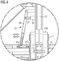
- the raising device 1 comprises a blocking mechanism 25 the function and details of which will be explained with reference to Figs. 4 and 5 .
- the raising device 1 When the raising device 1 is raised by a raising machine such as a crane, it is connected to that raising machine via the connection member 3 which is thus raised in an upward direction U. Reversely, when the raising device 1 is lowered to the ground, it is lowered in a downward direction D until the connection member 3 goes downwards into the position shown in Fig. 1 . At the same time, due to the movement mechanism of the raising device 1, the raising force while raising the raising device 1 in the upward direction is transferred via the four hinges 5, 9, 11, 13 into a moving force which tilts each of the holding members 19a, 19b, 19c, 19d in a locking direction L, i.e. out of the open position depicted in Fig. 1 into a locking position.
- this construction permits an automatic tilting movement of the holding members 19a, 19b, 19c, 19d in both the locking direction L and the counter direction A based on the force exerted on the connection member 3. No manual or motor support of that movement is necessary.
- the term “movement mechanism” refers to all those movable parts of the raising device 1 which interconnect the connection member 3 with the holding members 19a, 19b, 19c, 19d serving to transfer the raising (and lowering) forces inflicted on the connection member 3 into forces for moving the holding members 19a, 19b, 19c, 19d into or out of the locking position, i.e. in the locking direction L or the counter direction A.
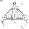
- Fig. 2 is a first side view of the same raising device 1 installed on top of a tower segment 31 of a wind turbine 100.
- the raising device 1 is thereby in a locked position, i.e. the holding members 19a, 19b, 19c, 19d have been moved completely in the locking direction L. Therefore they engage with an inwards protruding part (not shown) of an inner flange 29 of the tower segment 31 which inner flange 29 is comprised of the top element of the tower segment 31 which can be seen in Fig. 2 and of the inwards protruding part which cannot be seen.
- the holding members 19a, 19b, 19c, 19d are all orientated with their locking directions towards the inner surface of the tower segment 31, their lower part has been tilted below the inner flange 29 so that the holding members 19a, 19b, 19c, 19d facing into four directions and all orientated in a 90° angle to the next holding member hold the inwards protruding part of the inner flange 29 firmly from underneath.
- the feet 15 are positioned outside of the tower segment 31.
- Fig. 3 shows the same raising device 1 in a second side view which is perpendicular to the side view of Fig. 2 .
- the holding members 19a, 19b, 19c, 19d are positioned fixedly via their fourth hinges 13 to the first holding beam 21a along a predefined distance d.
- the locking direction L 1 of the holding member 19d at the right hand side is orientated away from the centre C of the raising device 1 further to the right whereas the locking direction L 2 of the holding member 19c at the left hand side faces exactly in the opposite direction.
- connection eye 33 projecting towards the centre C of the raising device 1.
- the blocking mechanism 25 comprises an inlet shell 35 for a pin 37 through which the pin 37 can be led inside the beam 30 (obscured in this figure due to the perspective).
- a handle 39 is connected to the pin 37 in order to facilitate manual (or motor-driven) movement of the pin 37 into the beam 30 and out again.
- two catch bolts 41a, 41b are positioned which are realized to firmly hold the handle 39 in a desired first, open, position (corresponding to the left catch bolt 41a) and in a desired second, blocked, position (corresponding to the right catch bolt 41b).
- the catch bolts 41a, 41b serve to fix the handle 39 in one of these two positions to prevent it from moving undesiredly.
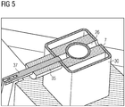
- Fig. 5 shows a section view of the beam 30 with its inner guiding beam 7.
- the guiding beam 7 comprises two recesses 26 along its longitudinal extension (i.e. the upward direction U and the downward direction D) one of which is depicted in Fig. 5 .
- the pin 37 can thus be inserted into the recesses 26 of the guiding beam 7 thus blocking the guiding beam 7 in its position and further blocking any movement of the movement mechanism.
- Figs. 6 and 7 this shows the same raising device 1 which is further equipped with a cover 43.
- the cover 43 is connected to the raising device via 1 the connection eyes 33 (cf. Fig. 3 ) and serves to shield the inner side of the tower segment 31 from the ambient environment, in particular from rain or snow.
- the cover 43 comprises a first opening 47 realized as a service hatch 47 through which staff can climb in order to get from the inside of the tower segment 31 to the upper side of the cover 43 or reverse.
- the cover 43 comprises four through-openings 45 through which the holding members 19a, 19b, 19c, 19d are inserted.
- Fig. 8 shows a schematic block diagram of an embodiment of an equipment method Z according to the invention. Thereby, reference is made to the embodiment of the raising device explained in the previous figures.
- the method comprises the following steps in the given sequence of actions:
Landscapes
- Engineering & Computer Science (AREA)
- Mechanical Engineering (AREA)
- Architecture (AREA)
- Life Sciences & Earth Sciences (AREA)
- Sustainable Development (AREA)
- Sustainable Energy (AREA)
- Chemical & Material Sciences (AREA)
- Combustion & Propulsion (AREA)
- General Engineering & Computer Science (AREA)
- Civil Engineering (AREA)
- Structural Engineering (AREA)
- Wind Motors (AREA)
Claims (14)
- Dispositif de levage (1) conçu pour être raccordé à un segment de tour (31) d'éolienne (100), comprenant un organe de raccordement (3) à un engin de levage et une pluralité d'organes de maintien (19a, 19b, 19c, 19d) positionnés à des distances prédéfinies (d) les uns par rapport aux autres et orientés pour être mobiles dans des directions radiales de verrouillage (L, L1, L2), lesquelles directions de verrouillage (L, L1, L2) sont telles que les organes de maintien (19a, 19b, 19c, 19d), lorsqu'ils sont déplacés vers une position de verrouillage à une position prédéfinie de mise en prise du segment de tour (31), entrent en prise avec une contreforme du segment de tour (31),
caractérisé en ce que les organes de maintien (19a, 19b, 19c, 19d) peuvent être automatiquement inclinés et/ou déplacés vers la position de verrouillage par un mécanisme de mouvement, de sorte que les organes de maintien (19a, 19b, 19c, 19d) sont mécaniquement reliés par l'intermédiaire du mécanisme de mouvement à l'organe de raccordement (3) par l'intermédiaire d'un certain nombre de charnières (5, 9, 11, 13), de manière que lors de la traction de l'organe de raccordement (3) vers le haut, les organes de maintien (19a, 19b, 19c, 19d) s'inclinent et/ou se déplacent automatiquement vers la position de verrouillage, à moins d'être bloqués. - Dispositif de levage selon la revendication 1, dans lequel chaque organe de maintien (19a, 19b, 19c, 19d) comprend une griffe (19a, 19b, 19c, 19d).
- Dispositif de levage selon la revendication 1 ou 2, dans lequel au moins deux organes de maintien correspondants (19a, 19b, 19c, 19d) sont alignés le long d'une ligne droite.
- Dispositif de levage selon la revendication 3, dans lequel les organes de maintien correspondants (19a, 19b, 19c, 19d) sont reliés à une poutre de maintien commune (21a, 21b).
- Dispositif de levage selon la revendication 4, dans lequel une première paire d'organes de maintien correspondants (19a, 19b) est reliée à une première poutre de maintien commune (21a) et une seconde paire d'organes de maintien correspondants (19c, 19d) est reliée à une seconde poutre de maintien commune (21b) qui est conçue comme une traverse (21b) de la première poutre de maintien (21a).
- Dispositif de levage selon la revendication 5, dans lequel la première poutre de maintien (21a) et la seconde poutre de maintien (21b) sont reliées entre elles par un certain nombre de raccords diagonaux (23).
- Dispositif de levage selon l'une quelconque des revendications précédentes, dans lequel les organes de maintien (19a, 19b, 19c, 19d) sont installés à demeure à la distance prédéfinie (d).
- Dispositif de levage selon l'une quelconque des revendications précédentes, dans lequel les organes de maintien (19a, 19b, 19c, 19d) sont conçus pour entrer en prise avec une bride supérieure (29) du segment de tour (31) le long de sa circonférence, laquelle bride supérieure (29) comprend la contreforme.
- Dispositif de levage selon l'une quelconque des revendications précédentes, comprenant un mécanisme de blocage (25) conçu pour bloquer un mouvement des organes de maintien (19a, 19b, 19c, 19d) dans et/ou hors de la position de verrouillage.
- Dispositif de levage selon la revendication 9, dans lequel le mécanisme de blocage (25) comprend une broche (37) qui entre en prise avec un évidement (26) d'élément mobile (7) du dispositif de levage, lequel élément mobile (26) est relié à l'un au moins des organes de maintien (19a, 19b, 19c, 19d) afin de bloquer un mouvement de cet organe de maintien (19a, 19b, 19c, 19d).
- Dispositif de levage selon l'une quelconque des revendications précédentes, comprenant en outre un couvercle (35) conçu pour recouvrir une partie ouverte du segment de tour (31).
- Dispositif de levage selon la revendication 11, dans lequel le couvercle présente au moins une ouverture (37, 39) conçue comme une ouverture d'entretien (39) destinée au personnel et/ou comme un trou traversant (37) destiné à l'un au moins des organes de maintien (19a, 19b, 19c, 19d).
- Segment de tour (31) d'éolienne (100), équipée d'un dispositif de levage (1) selon l'une quelconque des revendications précédentes.
- Procédé (Z) pour équiper un segment de tour (31) d'éolienne (100) à des fins de transport, comprenant les étapes consistant à :- raccorder (Y) un dispositif de levage (1) doté d'un organe de raccordement (3) à un engin de levage, au segment de tour (31), le dispositif de levage (1) comprenant l'organe de raccordement et une pluralité d'organes de maintien (19a, 19b, 19c, 19d) positionnés à des distances prédéfinies (d) les uns par rapport aux autres et orientés pour être mobiles dans des directions radiales de verrouillage (L, L1, L2), lesquelles directions de verrouillage (L, L1, L2) sont telles que les organes de maintien (19a, 19b, 19c, 19d), lorsqu'ils sont déplacés vers une position de verrouillage à une position prédéfinie de mise en prise du segment de tour (31), entrent en prise avec une contreforme du segment de tour (31), de sorte que les organes de maintien (19a, 19b, 19c, 19d) peuvent être automatiquement inclinés et/ou déplacés vers la position de verrouillage par un mécanisme de mouvement, de sorte que les organes de maintien (19a, 19b, 19c, 19d) sont mécaniquement reliés par l'intermédiaire du mécanisme de mouvement à l'organe de raccordement (3) par l'intermédiaire d'un certain nombre de charnières (5, 9, 11, 13), de manière que lors de la traction de l'organe de raccordement (3) vers le haut, les organes de maintien (19a, 19b, 19c, 19d) s'inclinent et/ou se déplacent automatiquement vers la position de verrouillage, à moins d'être bloqués,- incliner et/ou déplacer (X) les organes de maintien (19a, 19b, 19c, 19d) vers la position de verrouillage à la position prédéfinie de mise en prise du segment de tour (31) entrant en prise avec la contreforme,- éventuellement soulever (W) le dispositif de levage (1) au moyen de l'engin de levage.
Priority Applications (4)
| Application Number | Priority Date | Filing Date | Title |
|---|---|---|---|
| EP13176120.7A EP2824057B1 (fr) | 2013-07-11 | 2013-07-11 | Élévation d'un segment de tour |
| DK13176120.7T DK2824057T3 (en) | 2013-07-11 | 2013-07-11 | Lifting of a tower segment |
| US14/264,250 US9663330B2 (en) | 2013-07-11 | 2014-04-29 | Raising device configured to be connected to a tower segment |
| CN201410329774.9A CN104279131B (zh) | 2013-07-11 | 2014-07-11 | 抬升塔架节段 |
Applications Claiming Priority (1)
| Application Number | Priority Date | Filing Date | Title |
|---|---|---|---|
| EP13176120.7A EP2824057B1 (fr) | 2013-07-11 | 2013-07-11 | Élévation d'un segment de tour |
Publications (2)
| Publication Number | Publication Date |
|---|---|
| EP2824057A1 EP2824057A1 (fr) | 2015-01-14 |
| EP2824057B1 true EP2824057B1 (fr) | 2017-06-28 |
Family
ID=48790227
Family Applications (1)
| Application Number | Title | Priority Date | Filing Date |
|---|---|---|---|
| EP13176120.7A Active EP2824057B1 (fr) | 2013-07-11 | 2013-07-11 | Élévation d'un segment de tour |
Country Status (4)
| Country | Link |
|---|---|
| US (1) | US9663330B2 (fr) |
| EP (1) | EP2824057B1 (fr) |
| CN (1) | CN104279131B (fr) |
| DK (1) | DK2824057T3 (fr) |
Cited By (1)
| Publication number | Priority date | Publication date | Assignee | Title |
|---|---|---|---|---|
| DE102017011085A1 (de) | 2017-11-30 | 2019-06-06 | Senvion Gmbh | Hebevorrichtung und Verfahren zum Heben einer schweren Komponente einer Windenergieanlage |
Families Citing this family (17)
| Publication number | Priority date | Publication date | Assignee | Title |
|---|---|---|---|---|
| EP2937561B1 (fr) | 2014-04-25 | 2018-03-07 | Siemens Aktiengesellschaft | Agencement de support d'une tour d'éolienne |
| WO2016153367A1 (fr) * | 2015-03-25 | 2016-09-29 | Tacn Sp. Z O.O. | Dispositif de support de pièces de construction cylindriques |
| NL2014823B1 (en) * | 2015-05-19 | 2017-01-31 | Ihc Holland Ie Bv | Flange lifting tool. |
| ES2911709T3 (es) * | 2016-02-26 | 2022-05-20 | Nordex Energy Spain S A | Procedimiento de fabricación de torres de hormigón para aerogeneradores |
| CN106629386B (zh) * | 2016-12-29 | 2019-11-01 | 江苏金风科技有限公司 | 塔筒吊装吊具及吊装方法 |
| DE102017118658B3 (de) * | 2017-08-16 | 2019-02-21 | WP Systems GmbH | Vorrichtung und Verfahren zum Rückbauen und Zerkleinern vertikal ausgerichteter Objekte |
| NL2020809B1 (en) * | 2018-04-23 | 2019-10-31 | Ihc Holland Ie Bv | A lifting tool |
| ES2737373B2 (es) * | 2018-07-04 | 2020-09-09 | Telesforo Gonzalez Maqu Slu | Aparato para elevar verticalmente un bidon de carton corrugado prismatico octogonal hueco dotado de ocho caras laterales delgadas y lisas |
| BE1026068B9 (nl) * | 2018-07-26 | 2019-10-02 | Deme Offshore Holding N V | Inrichting en werkwijze voor het vanaf een steunvlak aan een uiteinde oprichten van een buisvormig element met een lengterichting |
| BE1026067B1 (nl) * | 2018-07-26 | 2019-09-26 | DEME Offshore Holding N.V. | Koppeltuig voor verbinding met een uiteinde van een buisvormig element ter oprichting van het element |
| WO2020233763A1 (fr) * | 2019-05-21 | 2020-11-26 | Vestas Wind Systems A/S | Ensemble outil pour tendre des boulons de tour d'une tour d'éolienne |
| CN110194411A (zh) * | 2019-05-30 | 2019-09-03 | 福建金风科技有限公司 | 塔筒吊具 |
| TWI730449B (zh) * | 2019-10-15 | 2021-06-11 | 潤弘精密工程事業股份有限公司 | 吊裝裝置及使用該吊裝裝置之吊裝方法 |
| DE102021000427A1 (de) | 2020-08-25 | 2022-03-03 | Wörmann Team GmbH & Co. KG | Vorrichtung und Verfahren zum Demontieren eines Betonturms, insbesondere Betonsegmentturms, einer Windenergieanlage |
| CA3139176C (fr) | 2020-12-04 | 2024-07-02 | Refractory Intellectual Property Gmbh & Co. Kg | Bague refractaire et systeme et methodes de bague refractaire aux fins d'assemblagee |
| DK4043722T3 (da) * | 2021-02-15 | 2023-11-20 | Siemens Gamesa Renewable Energy As | Transportsystem og fremgangsmåde til transport af et tårn til en vindmølle |
| KR102650837B1 (ko) * | 2021-10-06 | 2024-03-22 | 박상화 | 반자동 록킹 및 언록킹 기능을 갖는 중량물 인양장치 |
Family Cites Families (24)
| Publication number | Priority date | Publication date | Assignee | Title |
|---|---|---|---|---|
| US168707A (en) * | 1875-10-11 | Improvement in apparatus for walling wells | ||
| US1311361A (en) * | 1919-07-29 | Gamerel | ||
| US2327005A (en) * | 1942-06-01 | 1943-08-17 | Lloyd L Babcock | Barrel lifting means |
| US2370482A (en) * | 1942-10-07 | 1945-02-27 | Morgan Construction Co | Wire-block stripper |
| US3033605A (en) * | 1960-12-13 | 1962-05-08 | Jr John Morrow | Expansion-type grapple for lifting and carrying loads |
| US3104126A (en) * | 1961-01-09 | 1963-09-17 | Syncro Mach Co | Coil stripper |
| US3211490A (en) * | 1963-04-01 | 1965-10-12 | Gardner Engineering Corp | Hoist attachments |
| DK103738C (da) * | 1963-04-05 | 1966-02-14 | Gunnar Ivar Fredholm | Gribeværktøj til ved hjælp af et hejseapparat at løfte et kar med en centralt anbragt løfteåbning. |
| US3264027A (en) * | 1964-09-02 | 1966-08-02 | Beaunit Corp | Doffing tool |
| US3330591A (en) * | 1965-10-13 | 1967-07-11 | Clement C Pavelka | Oil drum grappling hook |
| US3935954A (en) * | 1974-07-08 | 1976-02-03 | Woods Donald L | Compacted hay transport |
| US5306062A (en) * | 1993-04-21 | 1994-04-26 | Dodge John P | Adjustable lifting device for sewer frame or the like |
| US5476300A (en) * | 1993-04-21 | 1995-12-19 | Dodge; John P. | Adjustable lifting device for sewer frame or the like |
| US6042165A (en) * | 1999-11-09 | 2000-03-28 | Thompson; Irvin | Pick-up box lift |
| US6840730B2 (en) * | 2000-01-21 | 2005-01-11 | Emmanuel P. Noualy | Bale moving apparatus |
| US20010001525A1 (en) * | 2000-04-25 | 2001-05-24 | John Shepard | Apparatus and methods for lifting containers |
| JP3302006B2 (ja) * | 2000-04-28 | 2002-07-15 | 象印チエンブロック株式会社 | スリング |
| US7237815B2 (en) * | 2004-03-15 | 2007-07-03 | Nucor Corporation | Lifting apparatus |
| US20090044482A1 (en) * | 2007-01-30 | 2009-02-19 | Tooman Norman L | Wind turbine installation comprising an apparatus for protection of anchor bolts and method of installation |
| EP2402278B1 (fr) | 2010-06-29 | 2012-11-21 | Siemens Aktiengesellschaft | Agencement pour lever une partie d'un mur de tour d'éolienne et procédé de levage d'une partie de mur de tour d'une éolienne |
| NL2005967C2 (en) * | 2011-01-07 | 2012-07-10 | Ihc Handling Systems Vof | Clamping device. |
| DE102011003164A1 (de) * | 2011-01-26 | 2012-07-26 | Aloys Wobben | Verfahren und Vorrichtung zum Errichten eines Turms einer Windenergieanlage |
| DE102011011603A1 (de) * | 2011-02-17 | 2012-08-23 | Martin Bode | Lastaufnahmemittel zum Anheben von schweren Komponenten oder Anlageteilen, insbesondere von Offshore-Anlagen |
| EP2824325B1 (fr) * | 2013-07-11 | 2017-10-18 | Siemens Aktiengesellschaft | Stockage de section de tour |
-
2013
- 2013-07-11 EP EP13176120.7A patent/EP2824057B1/fr active Active
- 2013-07-11 DK DK13176120.7T patent/DK2824057T3/en active
-
2014
- 2014-04-29 US US14/264,250 patent/US9663330B2/en active Active
- 2014-07-11 CN CN201410329774.9A patent/CN104279131B/zh active Active
Cited By (1)
| Publication number | Priority date | Publication date | Assignee | Title |
|---|---|---|---|---|
| DE102017011085A1 (de) | 2017-11-30 | 2019-06-06 | Senvion Gmbh | Hebevorrichtung und Verfahren zum Heben einer schweren Komponente einer Windenergieanlage |
Also Published As
| Publication number | Publication date |
|---|---|
| CN104279131A (zh) | 2015-01-14 |
| CN104279131B (zh) | 2019-02-12 |
| US9663330B2 (en) | 2017-05-30 |
| US20150016939A1 (en) | 2015-01-15 |
| DK2824057T3 (en) | 2017-09-11 |
| EP2824057A1 (fr) | 2015-01-14 |
Similar Documents
| Publication | Publication Date | Title |
|---|---|---|
| DK2824057T3 (en) | Lifting of a tower segment | |
| EP2851490B1 (fr) | Transport d'une tour d'éolienne | |
| JP6894016B2 (ja) | 洋上風車の浮体構造 | |
| US8572926B2 (en) | Lattice tower and an erection method for a wind turbine with a lattice tower | |
| AU2007321076B2 (en) | Device and process for rapid disassembly of a rotor and a nacelle from the mast of a windmill, as well as a windmill that is equipped with such a device | |
| US8251004B2 (en) | Device for transporting structures on water | |
| EP3191707B1 (fr) | Système et procédé pour retirer et/ou installer une pale de rotor d'une éolienne | |
| US10890157B2 (en) | Method and system for servicing wind turbine rotor | |
| CN114174209A (zh) | 具有吊机连接元件的风力涡轮机塔架和具有塔架凸缘连接元件的吊机 | |
| JP6824914B2 (ja) | 風力タービンコンポーネントを移動させる方法、及び風力タービンコンポーネントを移動させる搬送システム | |
| EP3091222A1 (fr) | Système et procédé de remplacement d'un palier de pale d'éolienne | |
| US11053704B1 (en) | Fixture for tilt-up wind turbine installation | |
| US9500178B2 (en) | Wind turbine rotor and method of mounting | |
| US9085444B2 (en) | Flexible articulated jib arm | |
| EP1978185B1 (fr) | Outil pour l'érection d'un segment de tour et procédé pour l'érection d'un segment de tour | |
| CN106801660A (zh) | 用于安装风力发电机的叶片的方法及设备 | |
| EP2532879B1 (fr) | Montage et/ou maintenance d'une éolienne | |
| WO2022119452A1 (fr) | Systèmes et procédés associés à l'ascension et à l'assemblage de structures de tour | |
| CN102040169A (zh) | 折叠塔 | |
| KR20260069565A (ko) | 블레이드 조립체 설치 장치, 로터 유닛, 풍력 발전설비, 블레이드 조립체 설치 방법, 그리고 상기 장치, 로터 유닛 및 풍력 발전설비의 용도 |
Legal Events
| Date | Code | Title | Description |
|---|---|---|---|
| 17P | Request for examination filed |
Effective date: 20130711 |
|
| AK | Designated contracting states |
Kind code of ref document: A1 Designated state(s): AL AT BE BG CH CY CZ DE DK EE ES FI FR GB GR HR HU IE IS IT LI LT LU LV MC MK MT NL NO PL PT RO RS SE SI SK SM TR |
|
| AX | Request for extension of the european patent |
Extension state: BA ME |
|
| PUAI | Public reference made under article 153(3) epc to a published international application that has entered the european phase |
Free format text: ORIGINAL CODE: 0009012 |
|
| R17P | Request for examination filed (corrected) |
Effective date: 20150714 |
|
| RBV | Designated contracting states (corrected) |
Designated state(s): AL AT BE BG CH CY CZ DE DK EE ES FI FR GB GR HR HU IE IS IT LI LT LU LV MC MK MT NL NO PL PT RO RS SE SI SK SM TR |
|
| GRAP | Despatch of communication of intention to grant a patent |
Free format text: ORIGINAL CODE: EPIDOSNIGR1 |
|
| STAA | Information on the status of an ep patent application or granted ep patent |
Free format text: STATUS: GRANT OF PATENT IS INTENDED |
|
| GRAJ | Information related to disapproval of communication of intention to grant by the applicant or resumption of examination proceedings by the epo deleted |
Free format text: ORIGINAL CODE: EPIDOSDIGR1 |
|
| GRAP | Despatch of communication of intention to grant a patent |
Free format text: ORIGINAL CODE: EPIDOSNIGR1 |
|
| RIC1 | Information provided on ipc code assigned before grant |
Ipc: B66C 1/44 20060101ALI20161020BHEP Ipc: B66C 1/62 20060101ALI20161020BHEP Ipc: B66C 1/10 20060101AFI20161020BHEP |
|
| GRAJ | Information related to disapproval of communication of intention to grant by the applicant or resumption of examination proceedings by the epo deleted |
Free format text: ORIGINAL CODE: EPIDOSDIGR1 |
|
| INTG | Intention to grant announced |
Effective date: 20161104 |
|
| GRAP | Despatch of communication of intention to grant a patent |
Free format text: ORIGINAL CODE: EPIDOSNIGR1 |
|
| GRAJ | Information related to disapproval of communication of intention to grant by the applicant or resumption of examination proceedings by the epo deleted |
Free format text: ORIGINAL CODE: EPIDOSDIGR1 |
|
| INTG | Intention to grant announced |
Effective date: 20161111 |
|
| GRAP | Despatch of communication of intention to grant a patent |
Free format text: ORIGINAL CODE: EPIDOSNIGR1 |
|
| GRAJ | Information related to disapproval of communication of intention to grant by the applicant or resumption of examination proceedings by the epo deleted |
Free format text: ORIGINAL CODE: EPIDOSDIGR1 |
|
| GRAP | Despatch of communication of intention to grant a patent |
Free format text: ORIGINAL CODE: EPIDOSNIGR1 |
|
| STAA | Information on the status of an ep patent application or granted ep patent |
Free format text: STATUS: REQUEST FOR EXAMINATION WAS MADE |
|
| GRAJ | Information related to disapproval of communication of intention to grant by the applicant or resumption of examination proceedings by the epo deleted |
Free format text: ORIGINAL CODE: EPIDOSDIGR1 |
|
| INTG | Intention to grant announced |
Effective date: 20161123 |
|
| INTG | Intention to grant announced |
Effective date: 20161202 |
|
| INTG | Intention to grant announced |
Effective date: 20161213 |
|
| GRAP | Despatch of communication of intention to grant a patent |
Free format text: ORIGINAL CODE: EPIDOSNIGR1 |
|
| STAA | Information on the status of an ep patent application or granted ep patent |
Free format text: STATUS: GRANT OF PATENT IS INTENDED |
|
| GRAJ | Information related to disapproval of communication of intention to grant by the applicant or resumption of examination proceedings by the epo deleted |
Free format text: ORIGINAL CODE: EPIDOSDIGR1 |
|
| INTG | Intention to grant announced |
Effective date: 20161221 |
|
| GRAP | Despatch of communication of intention to grant a patent |
Free format text: ORIGINAL CODE: EPIDOSNIGR1 |
|
| INTC | Intention to grant announced (deleted) | ||
| INTG | Intention to grant announced |
Effective date: 20170117 |
|
| INTG | Intention to grant announced |
Effective date: 20170126 |
|
| GRAS | Grant fee paid |
Free format text: ORIGINAL CODE: EPIDOSNIGR3 |
|
| GRAA | (expected) grant |
Free format text: ORIGINAL CODE: 0009210 |
|
| STAA | Information on the status of an ep patent application or granted ep patent |
Free format text: STATUS: THE PATENT HAS BEEN GRANTED |
|
| AK | Designated contracting states |
Kind code of ref document: B1 Designated state(s): AL AT BE BG CH CY CZ DE DK EE ES FI FR GB GR HR HU IE IS IT LI LT LU LV MC MK MT NL NO PL PT RO RS SE SI SK SM TR |
|
| REG | Reference to a national code |
Ref country code: GB Ref legal event code: FG4D |
|
| REG | Reference to a national code |
Ref country code: CH Ref legal event code: EP |
|
| REG | Reference to a national code |
Ref country code: FR Ref legal event code: PLFP Year of fee payment: 5 |
|
| REG | Reference to a national code |
Ref country code: AT Ref legal event code: REF Ref document number: 904660 Country of ref document: AT Kind code of ref document: T Effective date: 20170715 |
|
| REG | Reference to a national code |
Ref country code: IE Ref legal event code: FG4D |
|
| REG | Reference to a national code |
Ref country code: DE Ref legal event code: R096 Ref document number: 602013022760 Country of ref document: DE |
|
| RAP2 | Party data changed (patent owner data changed or rights of a patent transferred) |
Owner name: SIEMENS AKTIENGESELLSCHAFT |
|
| REG | Reference to a national code |
Ref country code: DK Ref legal event code: T3 Effective date: 20170906 |
|
| REG | Reference to a national code |
Ref country code: CH Ref legal event code: NV Representative=s name: SIEMENS SCHWEIZ AG, CH Ref country code: CH Ref legal event code: PCOW Free format text: NEW ADDRESS: WERNER-VON-SIEMENS-STRASSE 1, 80333 MUENCHEN (DE) |
|
| PG25 | Lapsed in a contracting state [announced via postgrant information from national office to epo] |
Ref country code: NO Free format text: LAPSE BECAUSE OF FAILURE TO SUBMIT A TRANSLATION OF THE DESCRIPTION OR TO PAY THE FEE WITHIN THE PRESCRIBED TIME-LIMIT Effective date: 20170928 Ref country code: GR Free format text: LAPSE BECAUSE OF FAILURE TO SUBMIT A TRANSLATION OF THE DESCRIPTION OR TO PAY THE FEE WITHIN THE PRESCRIBED TIME-LIMIT Effective date: 20170929 Ref country code: FI Free format text: LAPSE BECAUSE OF FAILURE TO SUBMIT A TRANSLATION OF THE DESCRIPTION OR TO PAY THE FEE WITHIN THE PRESCRIBED TIME-LIMIT Effective date: 20170628 Ref country code: HR Free format text: LAPSE BECAUSE OF FAILURE TO SUBMIT A TRANSLATION OF THE DESCRIPTION OR TO PAY THE FEE WITHIN THE PRESCRIBED TIME-LIMIT Effective date: 20170628 Ref country code: LT Free format text: LAPSE BECAUSE OF FAILURE TO SUBMIT A TRANSLATION OF THE DESCRIPTION OR TO PAY THE FEE WITHIN THE PRESCRIBED TIME-LIMIT Effective date: 20170628 |
|
| REG | Reference to a national code |
Ref country code: NL Ref legal event code: MP Effective date: 20170628 |
|
| REG | Reference to a national code |
Ref country code: LT Ref legal event code: MG4D |
|
| REG | Reference to a national code |
Ref country code: AT Ref legal event code: MK05 Ref document number: 904660 Country of ref document: AT Kind code of ref document: T Effective date: 20170628 |
|
| PG25 | Lapsed in a contracting state [announced via postgrant information from national office to epo] |
Ref country code: LV Free format text: LAPSE BECAUSE OF FAILURE TO SUBMIT A TRANSLATION OF THE DESCRIPTION OR TO PAY THE FEE WITHIN THE PRESCRIBED TIME-LIMIT Effective date: 20170628 Ref country code: SE Free format text: LAPSE BECAUSE OF FAILURE TO SUBMIT A TRANSLATION OF THE DESCRIPTION OR TO PAY THE FEE WITHIN THE PRESCRIBED TIME-LIMIT Effective date: 20170628 Ref country code: BG Free format text: LAPSE BECAUSE OF FAILURE TO SUBMIT A TRANSLATION OF THE DESCRIPTION OR TO PAY THE FEE WITHIN THE PRESCRIBED TIME-LIMIT Effective date: 20170928 Ref country code: RS Free format text: LAPSE BECAUSE OF FAILURE TO SUBMIT A TRANSLATION OF THE DESCRIPTION OR TO PAY THE FEE WITHIN THE PRESCRIBED TIME-LIMIT Effective date: 20170628 Ref country code: NL Free format text: LAPSE BECAUSE OF FAILURE TO SUBMIT A TRANSLATION OF THE DESCRIPTION OR TO PAY THE FEE WITHIN THE PRESCRIBED TIME-LIMIT Effective date: 20170628 |
|
| PG25 | Lapsed in a contracting state [announced via postgrant information from national office to epo] |
Ref country code: SK Free format text: LAPSE BECAUSE OF FAILURE TO SUBMIT A TRANSLATION OF THE DESCRIPTION OR TO PAY THE FEE WITHIN THE PRESCRIBED TIME-LIMIT Effective date: 20170628 Ref country code: CZ Free format text: LAPSE BECAUSE OF FAILURE TO SUBMIT A TRANSLATION OF THE DESCRIPTION OR TO PAY THE FEE WITHIN THE PRESCRIBED TIME-LIMIT Effective date: 20170628 Ref country code: AT Free format text: LAPSE BECAUSE OF FAILURE TO SUBMIT A TRANSLATION OF THE DESCRIPTION OR TO PAY THE FEE WITHIN THE PRESCRIBED TIME-LIMIT Effective date: 20170628 Ref country code: EE Free format text: LAPSE BECAUSE OF FAILURE TO SUBMIT A TRANSLATION OF THE DESCRIPTION OR TO PAY THE FEE WITHIN THE PRESCRIBED TIME-LIMIT Effective date: 20170628 Ref country code: RO Free format text: LAPSE BECAUSE OF FAILURE TO SUBMIT A TRANSLATION OF THE DESCRIPTION OR TO PAY THE FEE WITHIN THE PRESCRIBED TIME-LIMIT Effective date: 20170628 |
|
| PG25 | Lapsed in a contracting state [announced via postgrant information from national office to epo] |
Ref country code: ES Free format text: LAPSE BECAUSE OF FAILURE TO SUBMIT A TRANSLATION OF THE DESCRIPTION OR TO PAY THE FEE WITHIN THE PRESCRIBED TIME-LIMIT Effective date: 20170628 Ref country code: PL Free format text: LAPSE BECAUSE OF FAILURE TO SUBMIT A TRANSLATION OF THE DESCRIPTION OR TO PAY THE FEE WITHIN THE PRESCRIBED TIME-LIMIT Effective date: 20170628 Ref country code: IS Free format text: LAPSE BECAUSE OF FAILURE TO SUBMIT A TRANSLATION OF THE DESCRIPTION OR TO PAY THE FEE WITHIN THE PRESCRIBED TIME-LIMIT Effective date: 20171028 Ref country code: IT Free format text: LAPSE BECAUSE OF FAILURE TO SUBMIT A TRANSLATION OF THE DESCRIPTION OR TO PAY THE FEE WITHIN THE PRESCRIBED TIME-LIMIT Effective date: 20170628 Ref country code: SM Free format text: LAPSE BECAUSE OF FAILURE TO SUBMIT A TRANSLATION OF THE DESCRIPTION OR TO PAY THE FEE WITHIN THE PRESCRIBED TIME-LIMIT Effective date: 20170628 |
|
| REG | Reference to a national code |
Ref country code: CH Ref legal event code: PL |
|
| REG | Reference to a national code |
Ref country code: DE Ref legal event code: R097 Ref document number: 602013022760 Country of ref document: DE |
|
| PG25 | Lapsed in a contracting state [announced via postgrant information from national office to epo] |
Ref country code: MC Free format text: LAPSE BECAUSE OF FAILURE TO SUBMIT A TRANSLATION OF THE DESCRIPTION OR TO PAY THE FEE WITHIN THE PRESCRIBED TIME-LIMIT Effective date: 20170628 |
|
| REG | Reference to a national code |
Ref country code: IE Ref legal event code: MM4A |
|
| PG25 | Lapsed in a contracting state [announced via postgrant information from national office to epo] |
Ref country code: LI Free format text: LAPSE BECAUSE OF NON-PAYMENT OF DUE FEES Effective date: 20170731 Ref country code: IE Free format text: LAPSE BECAUSE OF NON-PAYMENT OF DUE FEES Effective date: 20170711 Ref country code: CH Free format text: LAPSE BECAUSE OF NON-PAYMENT OF DUE FEES Effective date: 20170731 |
|
| PLBE | No opposition filed within time limit |
Free format text: ORIGINAL CODE: 0009261 |
|
| 26N | No opposition filed |
Effective date: 20180329 |
|
| REG | Reference to a national code |
Ref country code: BE Ref legal event code: MM Effective date: 20170731 |
|
| PG25 | Lapsed in a contracting state [announced via postgrant information from national office to epo] |
Ref country code: LU Free format text: LAPSE BECAUSE OF NON-PAYMENT OF DUE FEES Effective date: 20170711 |
|
| REG | Reference to a national code |
Ref country code: FR Ref legal event code: PLFP Year of fee payment: 6 |
|
| PG25 | Lapsed in a contracting state [announced via postgrant information from national office to epo] |
Ref country code: BE Free format text: LAPSE BECAUSE OF NON-PAYMENT OF DUE FEES Effective date: 20170731 Ref country code: SI Free format text: LAPSE BECAUSE OF FAILURE TO SUBMIT A TRANSLATION OF THE DESCRIPTION OR TO PAY THE FEE WITHIN THE PRESCRIBED TIME-LIMIT Effective date: 20170628 |
|
| PG25 | Lapsed in a contracting state [announced via postgrant information from national office to epo] |
Ref country code: MT Free format text: LAPSE BECAUSE OF NON-PAYMENT OF DUE FEES Effective date: 20170711 |
|
| PG25 | Lapsed in a contracting state [announced via postgrant information from national office to epo] |
Ref country code: HU Free format text: LAPSE BECAUSE OF FAILURE TO SUBMIT A TRANSLATION OF THE DESCRIPTION OR TO PAY THE FEE WITHIN THE PRESCRIBED TIME-LIMIT; INVALID AB INITIO Effective date: 20130711 |
|
| REG | Reference to a national code |
Ref country code: DE Ref legal event code: R081 Ref document number: 602013022760 Country of ref document: DE Owner name: SIEMENS GAMESA RENEWABLE ENERGY A/S, DK Free format text: FORMER OWNER: SIEMENS AKTIENGESELLSCHAFT, 80333 MUENCHEN, DE |
|
| PG25 | Lapsed in a contracting state [announced via postgrant information from national office to epo] |
Ref country code: CY Free format text: LAPSE BECAUSE OF FAILURE TO SUBMIT A TRANSLATION OF THE DESCRIPTION OR TO PAY THE FEE WITHIN THE PRESCRIBED TIME-LIMIT Effective date: 20170628 |
|
| PG25 | Lapsed in a contracting state [announced via postgrant information from national office to epo] |
Ref country code: MK Free format text: LAPSE BECAUSE OF FAILURE TO SUBMIT A TRANSLATION OF THE DESCRIPTION OR TO PAY THE FEE WITHIN THE PRESCRIBED TIME-LIMIT Effective date: 20170628 |
|
| REG | Reference to a national code |
Ref country code: GB Ref legal event code: 732E Free format text: REGISTERED BETWEEN 20191128 AND 20191204 |
|
| PG25 | Lapsed in a contracting state [announced via postgrant information from national office to epo] |
Ref country code: TR Free format text: LAPSE BECAUSE OF FAILURE TO SUBMIT A TRANSLATION OF THE DESCRIPTION OR TO PAY THE FEE WITHIN THE PRESCRIBED TIME-LIMIT Effective date: 20170628 |
|
| PG25 | Lapsed in a contracting state [announced via postgrant information from national office to epo] |
Ref country code: PT Free format text: LAPSE BECAUSE OF FAILURE TO SUBMIT A TRANSLATION OF THE DESCRIPTION OR TO PAY THE FEE WITHIN THE PRESCRIBED TIME-LIMIT Effective date: 20170628 |
|
| PG25 | Lapsed in a contracting state [announced via postgrant information from national office to epo] |
Ref country code: AL Free format text: LAPSE BECAUSE OF FAILURE TO SUBMIT A TRANSLATION OF THE DESCRIPTION OR TO PAY THE FEE WITHIN THE PRESCRIBED TIME-LIMIT Effective date: 20170628 |
|
| STAA | Information on the status of an ep patent application or granted ep patent |
Free format text: STATUS: NO OPPOSITION FILED WITHIN TIME LIMIT |
|
| PGFP | Annual fee paid to national office [announced via postgrant information from national office to epo] |
Ref country code: DK Payment date: 20250725 Year of fee payment: 13 Ref country code: DE Payment date: 20250728 Year of fee payment: 13 |
|
| PGFP | Annual fee paid to national office [announced via postgrant information from national office to epo] |
Ref country code: GB Payment date: 20250722 Year of fee payment: 13 |
|
| PGFP | Annual fee paid to national office [announced via postgrant information from national office to epo] |
Ref country code: FR Payment date: 20250725 Year of fee payment: 13 |