EP2824257B2 - Procédé de fabrication et de montage d'une construction à mât tubulaire - Google Patents
Procédé de fabrication et de montage d'une construction à mât tubulaire Download PDFInfo
- Publication number
- EP2824257B2 EP2824257B2 EP14165927.6A EP14165927A EP2824257B2 EP 2824257 B2 EP2824257 B2 EP 2824257B2 EP 14165927 A EP14165927 A EP 14165927A EP 2824257 B2 EP2824257 B2 EP 2824257B2
- Authority
- EP
- European Patent Office
- Prior art keywords
- flanges
- flange
- tube
- tower structure
- pair
- Prior art date
- Legal status (The legal status is an assumption and is not a legal conclusion. Google has not performed a legal analysis and makes no representation as to the accuracy of the status listed.)
- Active
Links
Images


Classifications
-
- F—MECHANICAL ENGINEERING; LIGHTING; HEATING; WEAPONS; BLASTING
- F03—MACHINES OR ENGINES FOR LIQUIDS; WIND, SPRING, OR WEIGHT MOTORS; PRODUCING MECHANICAL POWER OR A REACTIVE PROPULSIVE THRUST, NOT OTHERWISE PROVIDED FOR
- F03D—WIND MOTORS
- F03D13/00—Assembly, mounting or commissioning of wind motors; Arrangements specially adapted for transporting wind motor components
- F03D13/20—Arrangements for mounting or supporting wind motors; Masts or towers for wind motors
-
- E—FIXED CONSTRUCTIONS
- E04—BUILDING
- E04H—BUILDINGS OR LIKE STRUCTURES FOR PARTICULAR PURPOSES; SWIMMING OR SPLASH BATHS OR POOLS; MASTS; FENCING; TENTS OR CANOPIES, IN GENERAL
- E04H12/00—Towers; Masts or poles; Chimney stacks; Water-towers; Methods of erecting such structures
- E04H12/02—Structures made of specified materials
- E04H12/08—Structures made of specified materials of metal
- E04H12/085—Details of flanges for tubular masts
-
- F—MECHANICAL ENGINEERING; LIGHTING; HEATING; WEAPONS; BLASTING
- F03—MACHINES OR ENGINES FOR LIQUIDS; WIND, SPRING, OR WEIGHT MOTORS; PRODUCING MECHANICAL POWER OR A REACTIVE PROPULSIVE THRUST, NOT OTHERWISE PROVIDED FOR
- F03D—WIND MOTORS
- F03D13/00—Assembly, mounting or commissioning of wind motors; Arrangements specially adapted for transporting wind motor components
- F03D13/10—Assembly of wind motors; Arrangements for erecting wind motors
-
- F—MECHANICAL ENGINEERING; LIGHTING; HEATING; WEAPONS; BLASTING
- F05—INDEXING SCHEMES RELATING TO ENGINES OR PUMPS IN VARIOUS SUBCLASSES OF CLASSES F01-F04
- F05B—INDEXING SCHEME RELATING TO WIND, SPRING, WEIGHT, INERTIA OR LIKE MOTORS, TO MACHINES OR ENGINES FOR LIQUIDS COVERED BY SUBCLASSES F03B, F03D AND F03G
- F05B2240/00—Components
- F05B2240/40—Use of a multiplicity of similar components
-
- Y—GENERAL TAGGING OF NEW TECHNOLOGICAL DEVELOPMENTS; GENERAL TAGGING OF CROSS-SECTIONAL TECHNOLOGIES SPANNING OVER SEVERAL SECTIONS OF THE IPC; TECHNICAL SUBJECTS COVERED BY FORMER USPC CROSS-REFERENCE ART COLLECTIONS [XRACs] AND DIGESTS
- Y02—TECHNOLOGIES OR APPLICATIONS FOR MITIGATION OR ADAPTATION AGAINST CLIMATE CHANGE
- Y02B—CLIMATE CHANGE MITIGATION TECHNOLOGIES RELATED TO BUILDINGS, e.g. HOUSING, HOUSE APPLIANCES OR RELATED END-USER APPLICATIONS
- Y02B10/00—Integration of renewable energy sources in buildings
- Y02B10/30—Wind power
-
- Y—GENERAL TAGGING OF NEW TECHNOLOGICAL DEVELOPMENTS; GENERAL TAGGING OF CROSS-SECTIONAL TECHNOLOGIES SPANNING OVER SEVERAL SECTIONS OF THE IPC; TECHNICAL SUBJECTS COVERED BY FORMER USPC CROSS-REFERENCE ART COLLECTIONS [XRACs] AND DIGESTS
- Y02—TECHNOLOGIES OR APPLICATIONS FOR MITIGATION OR ADAPTATION AGAINST CLIMATE CHANGE
- Y02E—REDUCTION OF GREENHOUSE GAS [GHG] EMISSIONS, RELATED TO ENERGY GENERATION, TRANSMISSION OR DISTRIBUTION
- Y02E10/00—Energy generation through renewable energy sources
- Y02E10/70—Wind energy
- Y02E10/72—Wind turbines with rotation axis in wind direction
-
- Y—GENERAL TAGGING OF NEW TECHNOLOGICAL DEVELOPMENTS; GENERAL TAGGING OF CROSS-SECTIONAL TECHNOLOGIES SPANNING OVER SEVERAL SECTIONS OF THE IPC; TECHNICAL SUBJECTS COVERED BY FORMER USPC CROSS-REFERENCE ART COLLECTIONS [XRACs] AND DIGESTS
- Y02—TECHNOLOGIES OR APPLICATIONS FOR MITIGATION OR ADAPTATION AGAINST CLIMATE CHANGE
- Y02E—REDUCTION OF GREENHOUSE GAS [GHG] EMISSIONS, RELATED TO ENERGY GENERATION, TRANSMISSION OR DISTRIBUTION
- Y02E10/00—Energy generation through renewable energy sources
- Y02E10/70—Wind energy
- Y02E10/728—Onshore wind turbines
Definitions
- the invention relates to a method for erecting tubular tower structures.
- Tubular tower structures are known, especially as supports for wind turbines. It is particularly known to produce pipe sections from sheet steel and to assemble the pipe sections one above the other with circumferential weld seams to form a pipe tower, which accommodates a wind energy nacelle at its upper end. In order to connect the individual segments to one another, it is known to either weld them or to provide them with circumferential flanges lying one on top of the other in such a way that the flanges lying on top of one another can be screwed together.
- a wind turbine tower segment which is also designed as a jacket segment and consists of a reinforced concrete body, with two joints for attaching to joints of at least one further tower segment and at least one connecting body is embedded in the reinforced concrete body in the area of each joint and is anchored therein for connecting to a connecting body adjacent tower segment and the connecting body has a fastening wall arranged essentially parallel to the respective joint for absorbing a tensile load directed transversely to the joint and transversely to the fastening wall.
- the disadvantage of such a device is that it is relatively complex to cast such concrete shells and also to produce them with precise fit and dimensions. Furthermore, the dismantling of such reinforced concrete towers is quite complex and expensive.
- a tower with an adapter piece and a method for producing a tower with the adapter piece are known, in which case a lower tubular tower section is also made of concrete and an upper tubular tower section is made of steel.
- Such hybrid towers are currently preferred for the construction of particularly tall wind turbine towers, since large diameters are possible with the concrete substructure and conventional wind turbine towers can be placed on top of the substructure towers in this way in order to achieve greater heights and thus a better wind yield.
- the disadvantage here is that the dismantling of a concrete tower is relatively complex and the assembly effort for concrete towers is relatively high, especially due to the delivery of concrete.
- a tower for a wind turbine with a plurality of corner posts to form a custom-made structure is known, the corner posts each being composed of several interconnected partial profiles.
- the corner posts are each composed of several interconnected partial profiles in such a way that connection areas are formed on adjacent partial profiles, which, however, are bent out of the partial profiles.
- the disadvantage of this embodiment is that it makes precise and quick work more difficult.
- From the DE 10 2011 603 A1 is a load-carrying device for lifting heavy components or system parts, especially offshore systems.
- a wind turbine with a stationary vertical mast or tower on which the movable part of the wind turbine is arranged, the mast consisting at least partially of prefabricated wall parts, with several adjacent wall parts forming a substantially annular mast section.
- the wall parts or segments are made of reinforced concrete or another stone-like material and are already prefabricated. The concrete elements are fastened to one another with the start of tension.
- a wind turbine tower is known with a plurality of prefabricated tower segments, each of which has an upper and lower horizontal flange, one of the plurality of tower segments having at least two longitudinal flanges, each longitudinal flange having a first side for abutting against a first side of a further longitudinal flange and a second Side which is welded laterally to the lateral surface, the second side being opposite the first side.
- a wall section for a wind turbine tower comprising a first wall segment and a second wall segment, as well as a connecting element which has a first surface section which is attached to the first wall segment and extends in a first direction, a second surface section which is attached to the second wall segment is attached and extends in a second direction and comprises an intermediate section with an intermediate surface section extending transversely to the first direction and transversely to the second direction, the connecting element thereby being T-shaped and on a corresponding wall or two on one another abutting wall is placed and fastened to it with screw bolts that protrude through the wall.
- a tubular tower structure which consists of tubular tower building shells is formed, the tubular tower building shells being produced individually and after the tubular tower building shells have been produced, flanges are welded onto the longitudinal edges of these shells. The structure is then assembled from the shells and screwed to the flanges.
- the object of the invention is to create a method with which such tower structures can be erected more quickly and with greater precision and accuracy.
- a tower structure constructed according to the invention serves in particular as a substructure tower in order to set up a conventional tower to accommodate wind turbines and thereby achieve a greater height and thus better wind accessibility.
- Such towers are usually created from tower segments with a circular cross-section, placed one above the other and connected to one another. Due to the usual bridge height in Germany, very large tower cross-sections can no longer be realized from one-piece pipe sections or pipe segments.
- the tubular tower structure is first manufactured and erected completely at the place of manufacture, so that the tubular tower structure is constructed in partial lengths that can still be transported or, if the length is still transportable, in its full length.
- corresponding sheets or blanks are made from sheet steel, which are then rolled so that they abut one another with a longitudinal edge and form a ring segment or a pipe segment. This pipe segment is then welded to this abutting edge. Further pipe segments are placed on top and also welded until a complete pipe tower structure is formed.
- flanges are then welded axially from the outside onto the tower structure wall or from the inside onto the tower structure wall, corresponding to a desired number of partial shells, with two flanges lying next to each other always forming a pair of flanges and being welded on.
- a tubular tower structure that consists of four partial shells, a total of eight flanges are welded on the outside or inside in four pairs.
- the pipe is then separated between the respective pairs of flanges into the corresponding partial shells.
- the partial shells are then transported to the construction site where they are reassembled into a tubular tower structure and connected to each other through the flanges.
- the advantage of the invention is that the flanges and the welding of the flanges to the tubular tower structure wall are extremely precise and comprehensibly accurate.
- the flanges on the entire tubular tower structure can be aligned and fastened in a particularly good manner in order to achieve a weld. It is also advantageous that these welds and the subsequent separation of the tubular tower structure into the shell elements are carried out under comprehensible conditions at the place of manufacture, whereby a corresponding check can be carried out on the type of manufacture.
- the entire tower simply needs to be assembled from, for example, four shells and screwed together.
- a pipe section 1 is circular in cross-section and has an axial weld seam 3 connecting them on at least two mutually facing axial edges 2.
- the axial length of the pipe section 1 is essentially limited by the width of the bent steel sheet and the bending devices available.
- the pipe sections 1 are in particular conical, so that the diameter at one axial end is larger than that at the opposite axial end. In this way, a plurality of such conical pipe sections 1 can be used to create conical towers ( Fig. 9 ) achieve.
- the individual pipe sections 1 have, for example, a height of 1.5 to 3 m, with a pipe section 1 at the foot of a pipe tower structure 6 ( Fig. 9 ) has a diameter of, for example, 7 m and in the area of the head a diameter of 4.5 m.
- the conical pipe sections 1 are placed one above the other and welded all around in the area of their peripheral edges 5.
- the method according to the invention provides for one or more axially welded pipe sections 1 to be combined into a transportable length, with suitable transport devices also allowing a complete pipe tower structure 6 to be assembled from pipe sections 1.
- suitable transport devices also allowing a complete pipe tower structure 6 to be assembled from pipe sections 1.
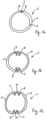
- the pipe tower structure 6 or a plurality of axially successive pipe sections 1 is first provided with a pair of longitudinal flanges 7, 8 in the area of desired dividing lines 20.
- the flanges 7, 8 can be on the outside ( Fig. 3 ) as well as inside ( Fig. 2 ) be arranged along planned dividing lines on the pipe wall 4.
- a pipe tower structure 6 or a pipe section 1 has two dividing lines 20, so that it can be separated into two half-shells 1a, with a flange 7, 8 remaining along an axial edge 11 formed by the separation.
- the flanges 7, 8 can be connected to one another; this connection can be a screw connection through existing screw holes 11 ( Fig. 11 ), be a rivet connection or a stitching with spot welds or short weld seams.
- this connection can be a screw connection through existing screw holes 11 ( Fig. 11 ), be a rivet connection or a stitching with spot welds or short weld seams.
- the flanges with broad sides 12 can be designed to lie against one another, but so-called lining plates or other spacers 13 can also be present between the flanges 7, 8 ( 8a to 8d ). This ensures good axial alignment and alignment of the flanges.
- a first flange 7 is rectangular in cross section and thus has two narrow sides 15, 16 running parallel to one another and two parallel has extending broad sides 12, attached and fixed with a narrow side 15 on the inner surface 14 of the wall 4.
- This flange is then welded to the surface 14, for example with fillet welds 17.
- the fillet welds can change the angle between Fill in areas 12 and 14.
- corresponding bevels can also be present in the area between the walls or surfaces 12 and the end face 15 of the flange, so that the seams 17 do not protrude.
- the second flange 8 is then placed parallel to the first flange 7 on the surface 14 and welded to the surface 14 with at least one fillet weld 18.
- the wide surface 12 of the flange 8 opposite the fillet weld 18 is difficult or impossible to reach for welding.
- a separation 20 is carried out along a desired dividing line that runs between the flanges 7, 8 and then the two shells 1a are separated from one another, so that the previously unwelded area of the flange 8 is accessible and can also be connected to the surface 14 with a seam.
- edges 21 of the partial shells 1a resulting from the separation and the mutually facing surfaces 12 of the flanges 7, 8 can be designed to be radially aligned.
- the flanges 7, 8 can also be arranged on the surface 14 at a small distance from the edges 21, slightly set back from them.
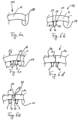
- the flanges 7, 8 are attached to the surface 14 with a so-called full connection ( Fig. 7a to 7f ).
- the flanges can already be connected to one another for fastening, in particular through screw holes 11 and with their surfaces 12 lying against one another ( Fig. 7a ), however, the flanges can also be arranged individually.
- the flanges 7, 8 have sloping end faces 15, so that they only rest on the surface 14 with a very narrow area and a notch results between the flanges 7, 8 and the surface 14, with the flanges arranged next to one another 7, 8 these notches are designed diametrically pointing away from each other.
- a weld seam root 23 can form when welding with full connection, which ultimately also connects the two flanges 7, 8 to one another ( Fig. 7e ).
- This weld seam root 23 must be removed in order to separate the two partial shells 1a from each other. This is conveniently achieved by separating ( Fig. 7f ), whereby the separation is carried out through the wall 4 of the pipe section 1 to such an extent that the weld root 23 is also removed, whereupon the partial shells 1a and thus also the flange 7, 8 can be separated from one another. In order to close the resulting gap, which would also occur again when screwing the flanges together, an appropriate lining plate or a seal can be inserted during assembly (between the front edges 21).
- Such lining plates or seals are arranged between the flanges 7, 8 or the edges 21 of the half-shells 1a in order to compensate for tolerances or to bring about a seal between the edges 21 or the flanges 7, 8.
- the lining plates can ( Fig. 8c ) between the flanges 7, 8 and between the edges 21 and extend outwards from the flanges 7, 8 through the wall 4 of the partial shells 1a. If the edges 21 abut each other firmly when assembled ( Fig. 8d ) lining plates can be present between the flanges 7, 8 set back to the edges 21.
- H or double-T sealing elements 24 can be arranged between the edges 21, although these can also be formed in one piece with the lining plates 13.
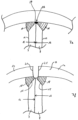
- a corresponding tubular tower structure 6 ( Fig. 9 ) thus has a plurality of dividing lines 20 in the erected state, with which the partial shells 1a consisting of the correspondingly connected segments of the pipe sections 1 are joined together.
- the tubular tower structure has an annular flange 24 on its smaller diameter end face 23.
- the annular flange 24 preferably consists of annular flange segments 24a, which are finally welded into the partial shells 1a at one end.
- annular flange 24 can be provided both at a narrower end of the tubular tower structure 6 and at a wider end of the tubular tower structure 6, in particular if the tubular tower structure 6 is part of a larger tubular tower structure (not shown) and between a wider part underneath and one above it located narrower part is arranged.
- Such an annular flange ( Fig. 13 ) is essentially annular with an inner circumferential surface 27, an outer circumferential surface 28, an end face 26 and an end face 29 running parallel to this.
- a connecting ring 30 is formed on the flange 24, which with respect to The radial extent has a thickness that approximately corresponds to the thickness of a wall of a tubular tower structure and is welded to the wall with this ring.
- tubular tower structure 6 is used as an intermediate part in a larger tubular tower structure, such a flange 24 is also arranged on the wall in the area of the largest diameter of the tubular tower structure.
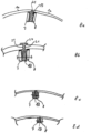
- annular flange 31 is provided on the bottom side on the wall of the tubular tower structure 6.
- the flange ring 31 is designed as a double ring with two concentric rows of holes 32, 33, the rows of holes 32, 33 being arranged axially with respect to the longitudinal extent of a tubular tower structure.
- the flange ring 31 forms a flat contact surface 34, a surface 35 running parallel to this, as well as an inner circumferential end face 36 and an outer circumferential end face 37.
- annular web 38 projects from the surface 35, the annular web 38 having a free, circumferential radial edge 39.
- the ring web 38 has a thickness that corresponds to the thickness of the wall 4 of a tubular tower structure. With the edge 39, the ring web 38 can be welded to a corresponding edge 40 of the tubular tower structure wall 4.
- a partial shell 6a of a corresponding tubular tower structure 6 ( Fig. 14 ) is a circular ring segment in cross section ( Fig. 15 partially cut), which is usually conical, so that the circular ring segment extends from a lower area ( Fig. 15 ) to an upper area ( Fig. 16 ) rejuvenated.
- the tubular tower structure segment 6a has a flange 7, 8 on each axial edge in the manner already described for connecting several segments, the flanges 7, 8 correspondingly having rows of holes through which the flanges 7, 8 can be connected to one another.
- the connection can generally be made using screws, rivets and welds. So-called locking ring bolts, which are ultimately screws placed on a threaded press sleeve and are maintenance-free or low-maintenance, have proven to be cheap.
- a tubular tower structure segment produced in the shape or a tubular tower structure shell 6a produced in this way has the already mentioned flanges 24, 31 at the upper and lower ends.
- the shells 6a are thus formed from a plurality of partial shells 1a or pipe sections 1a, the pipe sections 1a each having abutting edges 5 are placed on top of each other and welded together.
- Ring frames 40 or ring clamping segments 40 can be welded in approximately in the axial center between two abutting edges 5 for stabilization and, if necessary, for arranging components within a tower.
- a longitudinal frame 41 can be welded in the radial center between the two flanges 7, 8, which extends over the entire length or part of the length of the partial shell 6a.
- tubular tower structure 6 is manufactured entirely from tubular sections 1a, 6a, which are in particular conical, in a corresponding manufacturing facility.
- flanges which extend longitudinally or axially, are welded to the outside or inside of the pipe wall 4 and then the pipe tower structure between the flanges is separated into at least two partial shells 6a, preferably more partial shells 6a, in particular four to fourteen partial shells 6a , which are easy to transport, even on roads.
- the partial shells are connected to one another again, and this is done in a particularly simple manner since the partial shells are matched to one another with an absolutely precise fit.
- the assembly of such a tubular tower structure can be done in a fraction of the assembly time, with a pipe tower structure with very large diameters, in particular diameters at the base ⁇ 7 m, also being realized can be.
Landscapes
- Engineering & Computer Science (AREA)
- Chemical & Material Sciences (AREA)
- Life Sciences & Earth Sciences (AREA)
- Mechanical Engineering (AREA)
- Sustainable Energy (AREA)
- Combustion & Propulsion (AREA)
- Sustainable Development (AREA)
- General Engineering & Computer Science (AREA)
- Architecture (AREA)
- Materials Engineering (AREA)
- Wood Science & Technology (AREA)
- Civil Engineering (AREA)
- Structural Engineering (AREA)
- Wind Motors (AREA)
Claims (12)
- Procédé pour l'érection d'une construction de tour tubulaire,
dans lequel- une tôle d'acier est pliée en une section de tube (1a, b) de forme sensiblement annulaire en section transversale et soudée le long d'un bord longitudinal (2) en un tube fermé (1a, 1b),- au tube (6), le long de lignes de séparation axiales prévues, respectivement une paire de brides axiales (7, 8) est soudée à l'intérieur ou à l'extérieur sur la paroi du tube, respectivement une paire de brides (7, 8) étant disposée s'étendant axialement l'une à côté de l'autre dans la direction circonférentielle,- dans lequel, le long de lignes de séparation axiales prévues (20), qui s'étendent entre deux brides (7, 8) d'une paire de brides, le corps tubulaire (6) est séparé, de sorte qu'au moins deux coques partielles (6a) du corps tubulaire sont formées, qui présentent respectivement une bride (7, 8) le long de bords axiaux (11) et- pour la construction de la construction de tour, les coques partielles (6a) sont agencées ensemble au moyen des brides d'une paire de brides et sont reliées à travers les brides (7, 8) d'une paire de brides respective en un corps tubulaire. - Procédé selon la revendication 1,
caractérisé en ce
qu'une pluralité de sections de tube annulaires en section transversale (1a) sont reliées le long de bords radiaux communs s'étendant circonférentiellement et se rencontrant (5) pour former un corps tubulaire (6) s'étendant longitudinalement. - Procédé selon la revendication 1 ou 2,
caractérisé en ce que
les sections de tube (1a) sont agencées de telle manière que leurs paires de brides ou brides respectives et / ou soudures longitudinales sont décalés en direction axiale et ne sont pas disposées dans un alignement les unes aux autres. - Procédé selon l'une quelconque des revendications précédentes,
caractérisé en ce
qu'entre les brides (7, 8) d'une coque partielle (6a) des arceaux annulaires / des segments d'arceaux annulaires (40) et / ou des brides annulaires ou des segments débridés annulaires (24, 31) sont disposés, les brides annulaires (24, 31) étant agencées pour le reliage de sections de tube (6) axialement successives et en alignement avec des bords circonférentiels s'étendant radialement. - Procédé selon l'une quelconque des revendications précédentes, caractérisé en ce qued'abord une bride (7) d'une paire de brides (7, 8) est posée sur une face intérieure ou extérieure (14) de la paroi de tube (4) et reliée au corps tubulaire avec une première soudure d'angle (18) le long d'un bord de butée, etensuite le bord de butée opposé est soudé avec le corps tubulaire avec une soudure d'angle (18), etaprès la deuxième bride (8) de la paire de brides (7, 8) est disposé en butée à la première bride (7) ou légèrement espacé de celle-ci avec une soudure d'angle (18), en particulier espacé avec une distance correspondant à la largeur d'un outil de coupe, la soudure d'angle étant disposée opposé à la première bride de la paire de brides etpuis entre les deux brides (7, 8) de la paire de brides la séparation est réalisée,dans lequel, après la séparation, la deuxième bride (8) est fixée au corps tubulaire avec la deuxième soudure d'angle (18).
- Procédé selon l'une quelconque des revendications 1 à 4, caractérisé en ce
qu'une bride (7, 8) ou les deux brides (7, 8) sont placés sur un côté intérieur ou extérieur de la paroi de tube, les brides (7, 8) avec une face frontale (15) sont respectivement placées de telle manière, et la face frontale (15) s'étend de telle manière, qu'une fente en forme de coin est formée avec la paroi de tube et ensuite les brides sont soudées successivement ou simultanément à la paroi (4) avec une soudure de connexion continue. - Procédé selon l'une quelconque des revendications précédentes, caractérisé en ce que
la séparation est effectuée de telle sorte que le bord axial de la demi-coque est aligné avec le bord de butée de la bride, de sorte que lorsque une construction de tour est à être érigée, les brides de la demi-coque adjacente sont disposées directement adjacentes les unes aux autres. - Procédé selon l'une quelconque des revendications précédentes, caractérisé en ce que
la séparation est effectuée de telle sorte que chez des brides soudées avec une connexion continue et ayant une racine de soudure commune, la racine de soudure est éliminée lors de la séparation, de sorte que les brides (7, 8) ou les coquilles partielles (6a) peuvent être levées les unes des autres. - Procédé selon l'une quelconque des revendications précédentes, caractérisé en ce que
les paires de brides ou les brides de coquilles de construction de tour en butée l'une à l'autre sont reliées avec des boulons, des rivets, des vis avec douilles de serrage ou des boulons à sertir. - Procédé selon l'une quelconque des revendications précédentes, caractérisé en ce que
la construction de tour a un premier diamètre à une extrémité axiale et un second diamètre à une extrémité axialement opposée, le premier diamètre étant supérieur au second diamètre. - Procédé selon l'une quelconque des revendications précédentes, caractérisé en ce que
le plus petit diamètre est choisi de telle sorte qu'il correspond au diamètre standard des éoliennes dans leurs pieds, de sorte qu'une tour standard d'une éolienne peut être placé et fixé sur la section avec le diamètre inférieur de la construction tubulaire. - Procédé selon l'une quelconque des revendications précédentes, caractérisé en ce que
la construction de tour tubulaire (6) est formée à partir de deux à quatorze coquilles partielles préfabriquées et a un diamètre de pieds de 4 à 14 m et un diamètre de tête de 2,5 et 10 m.
Priority Applications (1)
| Application Number | Priority Date | Filing Date | Title |
|---|---|---|---|
| PL14165927.6T PL2824257T5 (pl) | 2013-07-04 | 2014-04-25 | Sposób wytwarzania oraz wznoszenia wieży rurowej |
Applications Claiming Priority (1)
| Application Number | Priority Date | Filing Date | Title |
|---|---|---|---|
| DE102013107059.0A DE102013107059B4 (de) | 2013-07-04 | 2013-07-04 | Verfahren zur Herstellung und zum Errichten eines Rohrturmbauwerks |
Publications (3)
| Publication Number | Publication Date |
|---|---|
| EP2824257A1 EP2824257A1 (fr) | 2015-01-14 |
| EP2824257B1 EP2824257B1 (fr) | 2017-08-16 |
| EP2824257B2 true EP2824257B2 (fr) | 2023-11-15 |
Family
ID=50630583
Family Applications (1)
| Application Number | Title | Priority Date | Filing Date |
|---|---|---|---|
| EP14165927.6A Active EP2824257B2 (fr) | 2013-07-04 | 2014-04-25 | Procédé de fabrication et de montage d'une construction à mât tubulaire |
Country Status (7)
| Country | Link |
|---|---|
| EP (1) | EP2824257B2 (fr) |
| DE (1) | DE102013107059B4 (fr) |
| DK (1) | DK2824257T4 (fr) |
| ES (1) | ES2646046T5 (fr) |
| FI (1) | FI2824257T4 (fr) |
| PL (1) | PL2824257T5 (fr) |
| PT (1) | PT2824257T (fr) |
Families Citing this family (24)
| Publication number | Priority date | Publication date | Assignee | Title |
|---|---|---|---|---|
| DE102013107059B4 (de) | 2013-07-04 | 2018-12-06 | SIAG Industrie GmbH | Verfahren zur Herstellung und zum Errichten eines Rohrturmbauwerks |
| DE102015204695A1 (de) * | 2015-03-16 | 2016-10-13 | Rwe Innogy Gmbh | Gründungspfahl für eine Windenergieanlage |
| DE102015211269A1 (de) | 2015-06-18 | 2016-12-22 | Wobben Properties Gmbh | Windenergieanlagen-Turm und Windenergieanlage |
| DE102015110344A1 (de) * | 2015-06-26 | 2016-12-29 | Eno Energy Systems Gmbh | Teilstück einer Turmsektion, ein Turm und ein Verfahren zum Herstellen eines Teilstücks einer Turmsektion |
| DE102016205447A1 (de) * | 2016-04-01 | 2017-10-05 | Innogy Se | Tragstruktur für eine Windenergieanlage |
| DE102016118549A1 (de) * | 2016-08-02 | 2018-02-08 | Eno Energy Systems Gmbh | Ein Verfahren zum Trennen einer Schale zumindest einer Turmsektion eines Turms und eine transportable Trennvorrichtung |
| EP3278915B1 (fr) * | 2016-08-02 | 2021-07-21 | eno energy systems GmbH | Procédé de séparation d'un plateau d'au moins une section de tour d'une tour et dispositif de séparation transportable |
| EP3339636A1 (fr) | 2016-12-22 | 2018-06-27 | Nordex Energy GmbH | Tour en acier pour éolienne et son procédé de fabrication |
| EP3339635A1 (fr) * | 2016-12-22 | 2018-06-27 | Nordex Energy GmbH | Tour en acier pour éolienne et son procédé de fabrication |
| DE102017120488A1 (de) | 2017-09-06 | 2019-03-07 | Nordex Energy Gmbh | Turm einer Windenergieanlage und Längsversteifung für einen Turm einer Windenergieanlage |
| CN107654338B (zh) * | 2017-09-30 | 2019-09-03 | 新疆金风科技股份有限公司 | 塔段、塔架、风力发电机组及塔段的制造方法 |
| DE102017125717A1 (de) * | 2017-11-03 | 2019-05-09 | Eno Energy Systems Gmbh | Verfahren zum Herstellen einer Teilsektion einer mehrteiligen Turmsektion |
| DE102017125716A1 (de) * | 2017-11-03 | 2019-05-09 | Eno Energy Systems Gmbh | Verfahren zum Errichten eines Turms mit einer mehrteiligen Turmsektion und Teilsektion einer mehrteiligen Turmsektion eines Turms |
| DK3724425T3 (da) * | 2017-12-11 | 2023-11-06 | Enovation Gmbh | Fremgangsmåde til fremstilling af en delsektion af en flerdelt tårnsektion til et tårn og delsektion af en flerdelt tårnsektion til et tårn |
| CN109185590B (zh) * | 2018-10-31 | 2024-07-02 | 江阴市扬子管件有限公司 | 一种节能环保高效集合管及其生产工艺 |
| KR102176840B1 (ko) * | 2018-12-07 | 2020-11-10 | 김성섭 | 발전소 연돌내부 연통구조물의 모듈화 시공방법 |
| EP3835516B1 (fr) * | 2019-12-11 | 2022-08-10 | Siemens Gamesa Renewable Energy Innovation & Technology, S.L. | Procédé de construction d'une tour métallique pour une éolienne |
| CN113404645B (zh) * | 2021-06-15 | 2024-04-02 | 中铁上海设计院集团有限公司 | 一种采用螺栓u环连接的风电混塔预制塔筒及其施工方法 |
| CN113751867A (zh) * | 2021-08-09 | 2021-12-07 | 成都凯天电子股份有限公司 | 一种用于薄壁回转体组件的激光焊加工方法 |
| CN114294173A (zh) * | 2021-12-20 | 2022-04-08 | 山东中车风电有限公司 | 一种大功率发电机组塔架及其施工方法 |
| CN114770030A (zh) * | 2021-12-29 | 2022-07-22 | 东北大学无锡研究院 | 一种风力发电机用变壁厚风塔及制造方法 |
| CN115059582A (zh) * | 2022-06-20 | 2022-09-16 | 福建工程学院 | 多边形风电塔筒分片式组合结构和风电塔筒及其应用 |
| CN115467785A (zh) * | 2022-10-31 | 2022-12-13 | 三一重能股份有限公司 | 一种塔筒段、塔筒及塔筒拼装方法 |
| EP4191056B1 (fr) * | 2023-03-27 | 2026-01-21 | Wobben Properties GmbH | Procédé de fabrication de sous-coques d'un segment de bague de tour en acier d'une tour d'une éolienne |
Citations (18)
| Publication number | Priority date | Publication date | Assignee | Title |
|---|---|---|---|---|
| US1765946A (en) † | 1928-03-29 | 1930-06-24 | Lou F Knowlton | Tank and joint for forming same |
| US1965966A (en) † | 1933-05-08 | 1934-07-10 | Ohno Hisajiro | Process of preserving fish |
| DE1099824B (de) † | 1959-07-03 | 1961-02-16 | Licentia Gmbh | Anwendung des Verfahrens zum Herstellen von geteilten Hohlkoerpern auf gehaeuseartige Schweisskonstruktionen, insbesondere geschweisste Turbinengehaeuse |
| US3738149A (en) † | 1971-10-01 | 1973-06-12 | B Archer | Pipe forming apparatus and method |
| DE2947355A1 (de) † | 1978-11-27 | 1980-06-04 | United Technologies Corp | Verfahren zum herstellen eines geteilten gehaeuses fuer ein gasturbinentriebwerk |
| JPS6471973A (en) † | 1987-09-11 | 1989-03-16 | Nippon Denro Mfg | Method of constructing hollow steel tower by steel plate assembly system |
| JPH07310460A (ja) † | 1994-03-24 | 1995-11-28 | Zeniraito V:Kk | 灯 台 |
| JPH08132232A (ja) † | 1994-11-08 | 1996-05-28 | Nkk Corp | ダイヤフラム付鋼管柱 |
| JPH08132275A (ja) † | 1994-11-08 | 1996-05-28 | Nkk Corp | ダイヤフラム付鋼管柱 |
| US6715243B1 (en) † | 1999-02-16 | 2004-04-06 | Jansens & Dieperink B.V. | Method for production of a silo |
| EP1606514A1 (fr) † | 2003-03-19 | 2005-12-21 | Vestas Wind System A/S | Procede de construction de grandes tours destinees a des turbines eoliennes |
| EP2149703A2 (fr) † | 2008-07-30 | 2010-02-03 | General Electric Company | Eolienne avec structure de montage pour la tour |
| DE202011001695U1 (de) † | 2011-01-19 | 2011-03-24 | K2E+C Gmbh | Stahlturm für Windkraftanlagen |
| DE102009055726A1 (de) † | 2009-11-26 | 2011-06-01 | Aerodyn Engineering Gmbh | Inneneinbauelement für den Rohrturm einer Windenergieanlage |
| EP2354379A2 (fr) † | 2010-02-08 | 2011-08-10 | Zeppelin Silos & Systems GmbH | Récipient doté de brides de liaison et d'une liaison interne soudée, notamment un silo |
| KR20120073785A (ko) † | 2010-12-27 | 2012-07-05 | 주식회사 포스코 | 풍력발전기용의 모듈러형 풍력발전탑 |
| US8322757B2 (en) † | 2007-01-26 | 2012-12-04 | Inner Mongolia Golden Ocean New Energy Technology Corporation Co., Ltd. | Coupling flange assembly for connecting steel pipes |
| DE102011077428A1 (de) † | 2011-06-10 | 2012-12-13 | Aloys Wobben | Windenergieanlagen-Turm |
Family Cites Families (10)
| Publication number | Priority date | Publication date | Assignee | Title |
|---|---|---|---|---|
| NL1019953C2 (nl) | 2002-02-12 | 2002-12-19 | Mecal Applied Mechanics B V | Geprefabriceerde toren of mast, alsmede een methode voor het samenvoegen en/of naspannen van segmenten die één constructie moeten vormen, alsmede een werkwijze voor het opbouwen van een toren of mast bestaande uit segmenten. |
| DE20321855U1 (de) * | 2003-03-19 | 2011-06-09 | Vestas Wind System A/S | Stahlturm für eine Windkraftanlage |
| US8474212B2 (en) | 2009-04-22 | 2013-07-02 | Rautaruukki Oyj | Tower for a wind power plant |
| DE102009058124B4 (de) | 2009-12-12 | 2012-03-08 | Fondasolutions S.A.R.L. | Montagevorrichtung für das Betonfundament einer Windkraftanlage sowie Verfahren zu dessen Herstellung |
| DE102010005991A1 (de) | 2010-01-27 | 2011-07-28 | Wobben, Aloys, Dipl.-Ing., 26607 | Windenergieanlage und Windenergieanlagen-Turmsegment |
| WO2011110235A2 (fr) | 2010-03-12 | 2011-09-15 | Siemens Aktiengesellschaft | Partie de paroi de tour d'éolienne |
| DE102010039796A1 (de) | 2010-06-14 | 2011-12-15 | Max Bögl Bauunternehmung GmbH & Co. KG | Turm mit einem Adapterstück sowie Verfahren zur Herstellung eines Turms mit einem Adapterstück |
| DE102011011603A1 (de) | 2011-02-17 | 2012-08-23 | Martin Bode | Lastaufnahmemittel zum Anheben von schweren Komponenten oder Anlageteilen, insbesondere von Offshore-Anlagen |
| DE102011001250A1 (de) | 2011-03-14 | 2012-09-20 | Strabag Offshore Wind Gmbh | Vorrichtung und Verfahren für den Übergang zwischen einem Stahlturmabschnitt und einem vorgespannten Betonturmabschnitt |
| DE102013107059B4 (de) | 2013-07-04 | 2018-12-06 | SIAG Industrie GmbH | Verfahren zur Herstellung und zum Errichten eines Rohrturmbauwerks |
-
2013
- 2013-07-04 DE DE102013107059.0A patent/DE102013107059B4/de not_active Withdrawn - After Issue
-
2014
- 2014-04-25 DK DK14165927.6T patent/DK2824257T4/da active
- 2014-04-25 EP EP14165927.6A patent/EP2824257B2/fr active Active
- 2014-04-25 PT PT141659276T patent/PT2824257T/pt unknown
- 2014-04-25 FI FIEP14165927.6T patent/FI2824257T4/fi active
- 2014-04-25 ES ES14165927T patent/ES2646046T5/es active Active
- 2014-04-25 PL PL14165927.6T patent/PL2824257T5/pl unknown
Patent Citations (20)
| Publication number | Priority date | Publication date | Assignee | Title |
|---|---|---|---|---|
| US1765946A (en) † | 1928-03-29 | 1930-06-24 | Lou F Knowlton | Tank and joint for forming same |
| US1965966A (en) † | 1933-05-08 | 1934-07-10 | Ohno Hisajiro | Process of preserving fish |
| DE1099824B (de) † | 1959-07-03 | 1961-02-16 | Licentia Gmbh | Anwendung des Verfahrens zum Herstellen von geteilten Hohlkoerpern auf gehaeuseartige Schweisskonstruktionen, insbesondere geschweisste Turbinengehaeuse |
| US3738149A (en) † | 1971-10-01 | 1973-06-12 | B Archer | Pipe forming apparatus and method |
| DE2947355A1 (de) † | 1978-11-27 | 1980-06-04 | United Technologies Corp | Verfahren zum herstellen eines geteilten gehaeuses fuer ein gasturbinentriebwerk |
| JPS6471973A (en) † | 1987-09-11 | 1989-03-16 | Nippon Denro Mfg | Method of constructing hollow steel tower by steel plate assembly system |
| JPH07310460A (ja) † | 1994-03-24 | 1995-11-28 | Zeniraito V:Kk | 灯 台 |
| JPH08132232A (ja) † | 1994-11-08 | 1996-05-28 | Nkk Corp | ダイヤフラム付鋼管柱 |
| JPH08132275A (ja) † | 1994-11-08 | 1996-05-28 | Nkk Corp | ダイヤフラム付鋼管柱 |
| US6715243B1 (en) † | 1999-02-16 | 2004-04-06 | Jansens & Dieperink B.V. | Method for production of a silo |
| EP1606514A1 (fr) † | 2003-03-19 | 2005-12-21 | Vestas Wind System A/S | Procede de construction de grandes tours destinees a des turbines eoliennes |
| US20060272244A1 (en) † | 2003-03-19 | 2006-12-07 | Jensen Soren P | Method of contructing large towers for wind turbines |
| DE60317372T2 (de) † | 2003-03-19 | 2008-08-21 | Vestas Wind Systems A/S | Gross bemessene türme für windkraftanlagen und verfahren zum erbauen solcher türme |
| US8322757B2 (en) † | 2007-01-26 | 2012-12-04 | Inner Mongolia Golden Ocean New Energy Technology Corporation Co., Ltd. | Coupling flange assembly for connecting steel pipes |
| EP2149703A2 (fr) † | 2008-07-30 | 2010-02-03 | General Electric Company | Eolienne avec structure de montage pour la tour |
| DE102009055726A1 (de) † | 2009-11-26 | 2011-06-01 | Aerodyn Engineering Gmbh | Inneneinbauelement für den Rohrturm einer Windenergieanlage |
| EP2354379A2 (fr) † | 2010-02-08 | 2011-08-10 | Zeppelin Silos & Systems GmbH | Récipient doté de brides de liaison et d'une liaison interne soudée, notamment un silo |
| KR20120073785A (ko) † | 2010-12-27 | 2012-07-05 | 주식회사 포스코 | 풍력발전기용의 모듈러형 풍력발전탑 |
| DE202011001695U1 (de) † | 2011-01-19 | 2011-03-24 | K2E+C Gmbh | Stahlturm für Windkraftanlagen |
| DE102011077428A1 (de) † | 2011-06-10 | 2012-12-13 | Aloys Wobben | Windenergieanlagen-Turm |
Non-Patent Citations (1)
| Title |
|---|
| "DANSKE VINDMOLLER (1): PORTRAET AF MICON'S 250 KW MOLLE" † |
Also Published As
| Publication number | Publication date |
|---|---|
| ES2646046T5 (es) | 2024-05-21 |
| EP2824257A1 (fr) | 2015-01-14 |
| PL2824257T3 (pl) | 2018-01-31 |
| DE102013107059A1 (de) | 2015-01-08 |
| ES2646046T3 (es) | 2017-12-11 |
| EP2824257B1 (fr) | 2017-08-16 |
| DK2824257T3 (da) | 2017-11-20 |
| DK2824257T4 (da) | 2024-01-15 |
| PL2824257T5 (pl) | 2024-03-04 |
| DE102013107059B4 (de) | 2018-12-06 |
| PT2824257T (pt) | 2017-11-14 |
| FI2824257T4 (fi) | 2024-02-05 |
Similar Documents
| Publication | Publication Date | Title |
|---|---|---|
| EP2824257B2 (fr) | Procédé de fabrication et de montage d'une construction à mât tubulaire | |
| EP2932095B1 (fr) | Élément de transition destiné à être disposé entre des portions exécutées différemment d'une tour d'éolienne et tour d'éolienne équipée dudit élément de transition | |
| EP3077670B1 (fr) | Élément de transition entre des parties d'une tour d'une éolienne et tour d'une éolienne comportant un élément de transition | |
| EP3760815B1 (fr) | Procédé de fabrication d'une pièce partielle d'une section de tour | |
| EP3230539B1 (fr) | Procédé pour ériger une construction de tour tubulaire et tour tubulaire | |
| EP2718519B1 (fr) | Tour éolienne | |
| EP3491239B1 (fr) | Élément de raccordement permettant de raccorder des sections de tour, section de tour, tour, éolienne ainsi que procédé de fabrication d'une section de tour et de raccordement de sections de tour | |
| WO2018029070A1 (fr) | Segment de mât, partie de mât, mât, éolienne ainsi que procédé permettant de fabriquer un segment de mât et de relier des segments de mât | |
| DE102015115645A1 (de) | Verfahren zur Herstellung und zum Errichten eines Rohrturmbauwerks | |
| EP2333163A1 (fr) | Structure offshore | |
| EP2288771B1 (fr) | Tour d'une éolienne | |
| DE102017120487A1 (de) | Turm einer Windenergieanlage und Verfahren zum Herstellen eines Sektionssegments für einen solchen Turm | |
| EP3183401B1 (fr) | Structure en béton modulaire | |
| EP3392502A1 (fr) | Tour d'une éolienne et procédé de montage d'une tour d'une éolienne | |
| EP3320161B1 (fr) | Tour d'une éolienne | |
| EP3658771B1 (fr) | Partie de tour en acier pour éoliennes, pour une tour d'éolienne et procédé pour la produire | |
| WO2017067692A1 (fr) | Tour d'éolienne | |
| EP2692967A2 (fr) | Procédé pour ériger un mât en acier d'une éolienne et mât en acier pour une éolienne | |
| DE102014118251B4 (de) | Verfahren zur Herstellung und zum Errichten eines Rohrturmbauwerks | |
| DE102017120488A1 (de) | Turm einer Windenergieanlage und Längsversteifung für einen Turm einer Windenergieanlage | |
| EP3467236A1 (fr) | Tour d'éolienne, en particulier pour une éolienne | |
| EP2708659B1 (fr) | Bride réglable pour une tour d'une installation éolienne | |
| EP3956561B1 (fr) | Section de tour et procédé pour la construction d'une tour | |
| EP3467204A1 (fr) | Manchon de raccordement permettant de raccorder une section de tour supérieur à une section de tour inférieur au moyen des profils de connexion | |
| DE102013201072A1 (de) | Flanschteil für einen Turm einer Windkraftanlage |
Legal Events
| Date | Code | Title | Description |
|---|---|---|---|
| 17P | Request for examination filed |
Effective date: 20140425 |
|
| AK | Designated contracting states |
Kind code of ref document: A1 Designated state(s): AL AT BE BG CH CY CZ DE DK EE ES FI FR GB GR HR HU IE IS IT LI LT LU LV MC MK MT NL NO PL PT RO RS SE SI SK SM TR |
|
| AX | Request for extension of the european patent |
Extension state: BA ME |
|
| PUAI | Public reference made under article 153(3) epc to a published international application that has entered the european phase |
Free format text: ORIGINAL CODE: 0009012 |
|
| RIN1 | Information on inventor provided before grant (corrected) |
Inventor name: KAISER, AXEL Inventor name: TATERRA, HERMANN-JOSEF |
|
| REG | Reference to a national code |
Ref country code: DE Ref legal event code: R079 Ref document number: 502014005025 Country of ref document: DE Free format text: PREVIOUS MAIN CLASS: E04H0012180000 Ipc: F03D0001000000 |
|
| GRAP | Despatch of communication of intention to grant a patent |
Free format text: ORIGINAL CODE: EPIDOSNIGR1 |
|
| STAA | Information on the status of an ep patent application or granted ep patent |
Free format text: STATUS: GRANT OF PATENT IS INTENDED |
|
| RIC1 | Information provided on ipc code assigned before grant |
Ipc: F03D 13/20 20160101ALI20161028BHEP Ipc: F03D 1/00 20060101AFI20161028BHEP Ipc: E04H 12/08 20060101ALI20161028BHEP |
|
| INTG | Intention to grant announced |
Effective date: 20161123 |
|
| GRAJ | Information related to disapproval of communication of intention to grant by the applicant or resumption of examination proceedings by the epo deleted |
Free format text: ORIGINAL CODE: EPIDOSDIGR1 |
|
| STAA | Information on the status of an ep patent application or granted ep patent |
Free format text: STATUS: REQUEST FOR EXAMINATION WAS MADE |
|
| INTC | Intention to grant announced (deleted) | ||
| GRAR | Information related to intention to grant a patent recorded |
Free format text: ORIGINAL CODE: EPIDOSNIGR71 |
|
| GRAS | Grant fee paid |
Free format text: ORIGINAL CODE: EPIDOSNIGR3 |
|
| STAA | Information on the status of an ep patent application or granted ep patent |
Free format text: STATUS: GRANT OF PATENT IS INTENDED |
|
| GRAA | (expected) grant |
Free format text: ORIGINAL CODE: 0009210 |
|
| STAA | Information on the status of an ep patent application or granted ep patent |
Free format text: STATUS: THE PATENT HAS BEEN GRANTED |
|
| INTG | Intention to grant announced |
Effective date: 20170706 |
|
| AK | Designated contracting states |
Kind code of ref document: B1 Designated state(s): AL AT BE BG CH CY CZ DE DK EE ES FI FR GB GR HR HU IE IS IT LI LT LU LV MC MK MT NL NO PL PT RO RS SE SI SK SM TR |
|
| REG | Reference to a national code |
Ref country code: GB Ref legal event code: FG4D Free format text: NOT ENGLISH |
|
| REG | Reference to a national code |
Ref country code: CH Ref legal event code: EP |
|
| REG | Reference to a national code |
Ref country code: IE Ref legal event code: FG4D Free format text: LANGUAGE OF EP DOCUMENT: GERMAN |
|
| REG | Reference to a national code |
Ref country code: AT Ref legal event code: REF Ref document number: 919325 Country of ref document: AT Kind code of ref document: T Effective date: 20170915 |
|
| REG | Reference to a national code |
Ref country code: DE Ref legal event code: R096 Ref document number: 502014005025 Country of ref document: DE |
|
| REG | Reference to a national code |
Ref country code: RO Ref legal event code: EPE |
|
| REG | Reference to a national code |
Ref country code: PT Ref legal event code: SC4A Ref document number: 2824257 Country of ref document: PT Date of ref document: 20171114 Kind code of ref document: T Free format text: AVAILABILITY OF NATIONAL TRANSLATION Effective date: 20171102 |
|
| REG | Reference to a national code |
Ref country code: DK Ref legal event code: T3 Effective date: 20171113 |
|
| REG | Reference to a national code |
Ref country code: SE Ref legal event code: TRGR |
|
| REG | Reference to a national code |
Ref country code: ES Ref legal event code: FG2A Ref document number: 2646046 Country of ref document: ES Kind code of ref document: T3 Effective date: 20171211 |
|
| REG | Reference to a national code |
Ref country code: NL Ref legal event code: MP Effective date: 20170816 |
|
| REG | Reference to a national code |
Ref country code: LT Ref legal event code: MG4D |
|
| PG25 | Lapsed in a contracting state [announced via postgrant information from national office to epo] |
Ref country code: LT Free format text: LAPSE BECAUSE OF FAILURE TO SUBMIT A TRANSLATION OF THE DESCRIPTION OR TO PAY THE FEE WITHIN THE PRESCRIBED TIME-LIMIT Effective date: 20170816 Ref country code: NL Free format text: LAPSE BECAUSE OF FAILURE TO SUBMIT A TRANSLATION OF THE DESCRIPTION OR TO PAY THE FEE WITHIN THE PRESCRIBED TIME-LIMIT Effective date: 20170816 Ref country code: NO Free format text: LAPSE BECAUSE OF FAILURE TO SUBMIT A TRANSLATION OF THE DESCRIPTION OR TO PAY THE FEE WITHIN THE PRESCRIBED TIME-LIMIT Effective date: 20171116 |
|
| PG25 | Lapsed in a contracting state [announced via postgrant information from national office to epo] |
Ref country code: IS Free format text: LAPSE BECAUSE OF FAILURE TO SUBMIT A TRANSLATION OF THE DESCRIPTION OR TO PAY THE FEE WITHIN THE PRESCRIBED TIME-LIMIT Effective date: 20171216 Ref country code: RS Free format text: LAPSE BECAUSE OF FAILURE TO SUBMIT A TRANSLATION OF THE DESCRIPTION OR TO PAY THE FEE WITHIN THE PRESCRIBED TIME-LIMIT Effective date: 20170816 Ref country code: LV Free format text: LAPSE BECAUSE OF FAILURE TO SUBMIT A TRANSLATION OF THE DESCRIPTION OR TO PAY THE FEE WITHIN THE PRESCRIBED TIME-LIMIT Effective date: 20170816 Ref country code: BG Free format text: LAPSE BECAUSE OF FAILURE TO SUBMIT A TRANSLATION OF THE DESCRIPTION OR TO PAY THE FEE WITHIN THE PRESCRIBED TIME-LIMIT Effective date: 20171116 |
|
| REG | Reference to a national code |
Ref country code: GR Ref legal event code: EP Ref document number: 20170402931 Country of ref document: GR Effective date: 20180330 |
|
| REG | Reference to a national code |
Ref country code: FR Ref legal event code: PLFP Year of fee payment: 5 |
|
| PG25 | Lapsed in a contracting state [announced via postgrant information from national office to epo] |
Ref country code: CZ Free format text: LAPSE BECAUSE OF FAILURE TO SUBMIT A TRANSLATION OF THE DESCRIPTION OR TO PAY THE FEE WITHIN THE PRESCRIBED TIME-LIMIT Effective date: 20170816 |
|
| REG | Reference to a national code |
Ref country code: DE Ref legal event code: R026 Ref document number: 502014005025 Country of ref document: DE |
|
| PLBI | Opposition filed |
Free format text: ORIGINAL CODE: 0009260 |
|
| PLAX | Notice of opposition and request to file observation + time limit sent |
Free format text: ORIGINAL CODE: EPIDOSNOBS2 |
|
| PG25 | Lapsed in a contracting state [announced via postgrant information from national office to epo] |
Ref country code: EE Free format text: LAPSE BECAUSE OF FAILURE TO SUBMIT A TRANSLATION OF THE DESCRIPTION OR TO PAY THE FEE WITHIN THE PRESCRIBED TIME-LIMIT Effective date: 20170816 Ref country code: SM Free format text: LAPSE BECAUSE OF FAILURE TO SUBMIT A TRANSLATION OF THE DESCRIPTION OR TO PAY THE FEE WITHIN THE PRESCRIBED TIME-LIMIT Effective date: 20170816 Ref country code: SK Free format text: LAPSE BECAUSE OF FAILURE TO SUBMIT A TRANSLATION OF THE DESCRIPTION OR TO PAY THE FEE WITHIN THE PRESCRIBED TIME-LIMIT Effective date: 20170816 Ref country code: IT Free format text: LAPSE BECAUSE OF FAILURE TO SUBMIT A TRANSLATION OF THE DESCRIPTION OR TO PAY THE FEE WITHIN THE PRESCRIBED TIME-LIMIT Effective date: 20170816 |
|
| 26 | Opposition filed |
Opponent name: NORDEX ENERGY GMBH Effective date: 20180516 Opponent name: ENERCON GMBH Effective date: 20180516 |
|
| PG25 | Lapsed in a contracting state [announced via postgrant information from national office to epo] |
Ref country code: SI Free format text: LAPSE BECAUSE OF FAILURE TO SUBMIT A TRANSLATION OF THE DESCRIPTION OR TO PAY THE FEE WITHIN THE PRESCRIBED TIME-LIMIT Effective date: 20170816 |
|
| PG25 | Lapsed in a contracting state [announced via postgrant information from national office to epo] |
Ref country code: MT Free format text: LAPSE BECAUSE OF FAILURE TO SUBMIT A TRANSLATION OF THE DESCRIPTION OR TO PAY THE FEE WITHIN THE PRESCRIBED TIME-LIMIT Effective date: 20170816 |
|
| PLBB | Reply of patent proprietor to notice(s) of opposition received |
Free format text: ORIGINAL CODE: EPIDOSNOBS3 |
|
| PG25 | Lapsed in a contracting state [announced via postgrant information from national office to epo] |
Ref country code: MC Free format text: LAPSE BECAUSE OF FAILURE TO SUBMIT A TRANSLATION OF THE DESCRIPTION OR TO PAY THE FEE WITHIN THE PRESCRIBED TIME-LIMIT Effective date: 20170816 |
|
| REG | Reference to a national code |
Ref country code: CH Ref legal event code: PL |
|
| REG | Reference to a national code |
Ref country code: BE Ref legal event code: MM Effective date: 20180430 |
|
| PG25 | Lapsed in a contracting state [announced via postgrant information from national office to epo] |
Ref country code: LU Free format text: LAPSE BECAUSE OF NON-PAYMENT OF DUE FEES Effective date: 20180425 |
|
| PG25 | Lapsed in a contracting state [announced via postgrant information from national office to epo] |
Ref country code: CH Free format text: LAPSE BECAUSE OF NON-PAYMENT OF DUE FEES Effective date: 20180430 Ref country code: LI Free format text: LAPSE BECAUSE OF NON-PAYMENT OF DUE FEES Effective date: 20180430 Ref country code: BE Free format text: LAPSE BECAUSE OF NON-PAYMENT OF DUE FEES Effective date: 20180430 |
|
| REG | Reference to a national code |
Ref country code: DE Ref legal event code: R082 Ref document number: 502014005025 Country of ref document: DE Representative=s name: HGF EUROPE LLP, DE Ref country code: DE Ref legal event code: R082 Ref document number: 502014005025 Country of ref document: DE Representative=s name: HGF EUROPE LP, DE |
|
| RIC2 | Information provided on ipc code assigned after grant |
Ipc: F03D 13/20 20160101ALI20200123BHEP Ipc: F03D 13/10 20160101AFI20200123BHEP Ipc: E04H 12/08 20060101ALI20200123BHEP |
|
| PG25 | Lapsed in a contracting state [announced via postgrant information from national office to epo] |
Ref country code: HU Free format text: LAPSE BECAUSE OF FAILURE TO SUBMIT A TRANSLATION OF THE DESCRIPTION OR TO PAY THE FEE WITHIN THE PRESCRIBED TIME-LIMIT; INVALID AB INITIO Effective date: 20140425 |
|
| PG25 | Lapsed in a contracting state [announced via postgrant information from national office to epo] |
Ref country code: MK Free format text: LAPSE BECAUSE OF NON-PAYMENT OF DUE FEES Effective date: 20170816 Ref country code: CY Free format text: LAPSE BECAUSE OF FAILURE TO SUBMIT A TRANSLATION OF THE DESCRIPTION OR TO PAY THE FEE WITHIN THE PRESCRIBED TIME-LIMIT Effective date: 20170816 Ref country code: HR Free format text: LAPSE BECAUSE OF FAILURE TO SUBMIT A TRANSLATION OF THE DESCRIPTION OR TO PAY THE FEE WITHIN THE PRESCRIBED TIME-LIMIT Effective date: 20170816 |
|
| APBM | Appeal reference recorded |
Free format text: ORIGINAL CODE: EPIDOSNREFNO |
|
| APBP | Date of receipt of notice of appeal recorded |
Free format text: ORIGINAL CODE: EPIDOSNNOA2O |
|
| APAH | Appeal reference modified |
Free format text: ORIGINAL CODE: EPIDOSCREFNO |
|
| PG25 | Lapsed in a contracting state [announced via postgrant information from national office to epo] |
Ref country code: AL Free format text: LAPSE BECAUSE OF FAILURE TO SUBMIT A TRANSLATION OF THE DESCRIPTION OR TO PAY THE FEE WITHIN THE PRESCRIBED TIME-LIMIT Effective date: 20170816 |
|
| REG | Reference to a national code |
Ref country code: AT Ref legal event code: MM01 Ref document number: 919325 Country of ref document: AT Kind code of ref document: T Effective date: 20190425 |
|
| APBQ | Date of receipt of statement of grounds of appeal recorded |
Free format text: ORIGINAL CODE: EPIDOSNNOA3O |
|
| PG25 | Lapsed in a contracting state [announced via postgrant information from national office to epo] |
Ref country code: AT Free format text: LAPSE BECAUSE OF NON-PAYMENT OF DUE FEES Effective date: 20190425 |
|
| APBU | Appeal procedure closed |
Free format text: ORIGINAL CODE: EPIDOSNNOA9O |
|
| P01 | Opt-out of the competence of the unified patent court (upc) registered |
Effective date: 20230526 |
|
| PUAH | Patent maintained in amended form |
Free format text: ORIGINAL CODE: 0009272 |
|
| STAA | Information on the status of an ep patent application or granted ep patent |
Free format text: STATUS: PATENT MAINTAINED AS AMENDED |
|
| 27A | Patent maintained in amended form |
Effective date: 20231115 |
|
| AK | Designated contracting states |
Kind code of ref document: B2 Designated state(s): AL AT BE BG CH CY CZ DE DK EE ES FI FR GB GR HR HU IE IS IT LI LT LU LV MC MK MT NL NO PL PT RO RS SE SI SK SM TR |
|
| REG | Reference to a national code |
Ref country code: DE Ref legal event code: R102 Ref document number: 502014005025 Country of ref document: DE |
|
| REG | Reference to a national code |
Ref country code: SE Ref legal event code: RPEO |
|
| REG | Reference to a national code |
Ref country code: DK Ref legal event code: T4 Effective date: 20240112 |
|
| REG | Reference to a national code |
Ref country code: GR Ref legal event code: EP Ref document number: 20240400054 Country of ref document: GR Effective date: 20240209 |
|
| REG | Reference to a national code |
Ref country code: ES Ref legal event code: DC2A Ref document number: 2646046 Country of ref document: ES Kind code of ref document: T5 Effective date: 20240521 |
|
| PGFP | Annual fee paid to national office [announced via postgrant information from national office to epo] |
Ref country code: PL Payment date: 20250319 Year of fee payment: 12 |
|
| PGFP | Annual fee paid to national office [announced via postgrant information from national office to epo] |
Ref country code: FI Payment date: 20250424 Year of fee payment: 12 |
|
| PGFP | Annual fee paid to national office [announced via postgrant information from national office to epo] |
Ref country code: DE Payment date: 20250417 Year of fee payment: 12 |
|
| PGFP | Annual fee paid to national office [announced via postgrant information from national office to epo] |
Ref country code: GB Payment date: 20250423 Year of fee payment: 12 Ref country code: ES Payment date: 20250529 Year of fee payment: 12 Ref country code: DK Payment date: 20250429 Year of fee payment: 12 |
|
| PGFP | Annual fee paid to national office [announced via postgrant information from national office to epo] |
Ref country code: PT Payment date: 20250417 Year of fee payment: 12 |
|
| PGFP | Annual fee paid to national office [announced via postgrant information from national office to epo] |
Ref country code: FR Payment date: 20250425 Year of fee payment: 12 |
|
| PGFP | Annual fee paid to national office [announced via postgrant information from national office to epo] |
Ref country code: GR Payment date: 20250423 Year of fee payment: 12 |
|
| PGFP | Annual fee paid to national office [announced via postgrant information from national office to epo] |
Ref country code: RO Payment date: 20250424 Year of fee payment: 12 |
|
| PGFP | Annual fee paid to national office [announced via postgrant information from national office to epo] |
Ref country code: TR Payment date: 20250421 Year of fee payment: 12 |
|
| PGFP | Annual fee paid to national office [announced via postgrant information from national office to epo] |
Ref country code: IE Payment date: 20250422 Year of fee payment: 12 |
|
| PGFP | Annual fee paid to national office [announced via postgrant information from national office to epo] |
Ref country code: SE Payment date: 20250429 Year of fee payment: 12 |