EP2824265A2 - Système de fixation - Google Patents
Système de fixation Download PDFInfo
- Publication number
- EP2824265A2 EP2824265A2 EP14172813.9A EP14172813A EP2824265A2 EP 2824265 A2 EP2824265 A2 EP 2824265A2 EP 14172813 A EP14172813 A EP 14172813A EP 2824265 A2 EP2824265 A2 EP 2824265A2
- Authority
- EP
- European Patent Office
- Prior art keywords
- fitting
- main wing
- skylight
- handle
- transferred
- Prior art date
- Legal status (The legal status is an assumption and is not a legal conclusion. Google has not performed a legal analysis and makes no representation as to the accuracy of the status listed.)
- Granted
Links
Images


Classifications
-
- E—FIXED CONSTRUCTIONS
- E05—LOCKS; KEYS; WINDOW OR DOOR FITTINGS; SAFES
- E05F—DEVICES FOR MOVING WINGS INTO OPEN OR CLOSED POSITION; CHECKS FOR WINGS; WING FITTINGS NOT OTHERWISE PROVIDED FOR, CONCERNED WITH THE FUNCTIONING OF THE WING
- E05F17/00—Special devices for shifting a plurality of wings operated simultaneously
Definitions
- the invention relates to a fitting system for windows, doors or the like, comprising at least one main wing and an overlying skylight, with a main wing associated, a central closure having rotary fitting and the top light associated tilting fitting. Furthermore, the invention is directed to a window or a door with such a fitting system.
- a skylight is a smaller window located above a main wing of a window, door or the like.
- Such skylights were previously either fixed or tilted by a rod or an electric drive.
- fixed skylights have the disadvantage that a ventilation is only possible up to this skylight and above the main wing creates a dead ventilation area. Accordingly, the relatively heavier main wing must be tiltable.
- the operation via a rod is relatively expensive.
- the provided for operating a skylight rods or electric drives are usually clearly visible and visually disturbing accordingly. Without a rod or electric drive, the skylight, however, is difficult to reach for opening.
- the invention has for its object to provide a fitting system of the type mentioned, the overall structure as simple as possible while avoiding a relatively complex and visually disturbing rod or electric drive and tilting of the skylights and thus allows for optimal ventilation.
- This object is achieved in that the main wing associated rotary fitting force and / or positively coupled with the top light associated tilting fitting that the tilting fitting of the skylight on the main wing associated central lock is actuated.
- the coupling fitting can be accommodated easily covered in the area between the main wing and the skylight.
- the previously required for tilting a skylight optically disturbing rod or electric drive can be omitted.
- the coupling fitting according to the invention can be easily retrofitted.
- the intended for the main wing and skylights fittings can be taken virtually unchanged. There is no greater maintenance than it is required anyway for the central closure of the main wing.
- the coupling fitting brings only a few additional parts with it, for virtually no additional space required.
- This coupling fitting can be concealed in the area between the main wing and the skylight, for example, in a arranged between the main wing and skylight cross member.
- the tilting fitting assigned to the overhead light preferably comprises a controlled opening scissors, by means of which the skylight can be adjusted by a corresponding actuation of the central closure associated with the main wing via the coupling fitting between a closed position and a tilted position.
- Such controlled scissors form a forced control over which the skylights can be moved directly from the closed position to the tilted position and back again by actuating the central closure associated with the main wing.
- the central closure associated with the main wing comprises a gripping gear which is provided with a handle which is adjustable between a downward, a horizontal and an upward position to different switching states of the rotation associated with the main wing -Bags as well as the top light associated tilting fitting bring about.
- the handle gear and the fittings are advantageously designed so that in a transfer of the handle from its downward position in its horizontal position and at a transfer of the handle from its upward position in his horizontal position give different switching states of the fittings.
- the handle gear and the fittings are preferably designed so that when transferring the handle from its downward position to its horizontal position of the main wing associated rotary fitting is transferred to an open state in which the main wing is released for its rotary opening, and the top light associated tilting fitting is transferred to a closed state in which the skylight is closed.
- the gripping gear and the fittings are designed so that in a transfer of the handle from its upward position in its horizontal position of the main wing associated rotary fitting is transferred to an open state in which the main wing for a rotary opening is released, and the top light associated tilting fitting is transferred to a tilted state in which the skylight is tilted.
- both the main wing associated rotary fitting and the top light associated tilting fitting is in each case converted into a closed state in which the main wing or the skylights is closed.
- the tilting fitting is designed as a turn-tilt fitting, in particular with an associated rotary opening handle for the skylight.
- the skylights can be easily opened for cleaning in a rotational position.
- Hanging the mechanism is not required for cleaning.
- With the possibility of a rotary opening a more thorough cleaning is possible than in the previously usual hinged skylights, which can be opened for cleaning usually only by 80 °.
- a separately open turnstile for the skylight can be provided. With such a turnstile can be achieved that the skylight remains locked, even if the turn-tilt fitting of the skylight is in its rotational opening position. A rotation opening of the skylight is in this case only possible when both the turn-tilt fitting is in its rotational opening position and when the turnstile is open.
- the gripping gear and the remaining fittings are designed so that when transferring the handle from its downward position or from its upward position in its horizontal position of the main wing associated rotary fitting is transferred to an open state in which the Main wing is released for a rotation opening, and the top light associated tilt-turn fitting is transferred to an open state in which the skylight is basically released for a rotation opening. Due to the turnstile, the skylight can only be opened if the turnstile has been opened separately, eg for cleaning.
- both the main wing associated rotary fitting and the top light associated with turn-tilt fitting each transferred to a closed state in which the main wing and the skylights is closed. More preferably, in its upwardly directed position engaging handle of the main wing associated rotary fitting is transferred to a closed state in which the main wing is closed, and the top light associated turn-tilt fitting transferred to a tilted state in which flipped the skylights is.
- a window or door according to the invention comprises at least one main wing and a skylight arranged above it and a fitting system designed according to the invention.
- the main wing can also be formed by the wing of a double-winged window, door or the like, which also comprises a wing under winging.
- Fig. 1 shows a schematic representation of a main wing 10 and an overlying skylight 12 comprehensive window 14.
- the main wing 10 is formed for example by the auf forden wing of a two-leaf window, which also includes a flap under wing 16.
- the main wing 10 is associated with a central closure 18 having rotary fitting and the skylight 12 a tilting fitting.
- the rotary fitting of the main wing 10 may be formed in particular in a wing groove, which is covered by a faceplate.
- the tilting fitting of the skylight 12 comprises a controlled opening shears 20.
- the main wing 10 associated rotary fitting is a in the Fig. 1
- dashed lines merely indicated coupling fitting 22 positively coupled with the top light 12 associated tilting fitting so that the tilting fitting of the skylight 12 can be actuated via the central flap 18 associated with the main wing 10.
- the coupling fitting 22 is concealed in the area between the main wing 10 and the skylight 12 housed.
- the Ausstellschere 20 of the skylight 12 associated tilting fitting is designed as a controlled Ausstellschere over which the skylights 12 by a corresponding operation of the main wing 10 assigned Central closure 18 is adjustable via the coupling fitting 22 between a closed and a tilted position.
- the main wing 10 associated central closure 18 comprises a gripping gear which is provided with a handle 24 which is adjustable between a downwardly directed, a horizontal and an upward position to different switching states of the main wing 10 associated rotary fitting and of the skylight 12 associated tilting fitting bring about.
- the handle gear and the remaining fittings of the main wing 10 and the skylight 12 are designed so that in a transfer of the handle 24 from its downward position in its horizontal position and at a transfer of the handle 24 from its upward position in his horizontal position different switching states of the fittings result (see FIGS. 3 and 5 ).
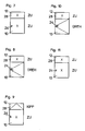
- Fig. 2 shows in a schematic representation of the switching states of the fittings of the main wing 10 and the skylight 12 in its downward position engaging handle 24 of the handle mechanism of the main wing 10. Thereafter, in his downwardly oriented position engaging handle 24 both the main wing 10 associated rotary fitting as well as the top light 12 associated tilting fitting each transferred to a closed state in which the main wing 10 and the skylight 12 is closed ("to").
- Fig. 3 shows a schematic representation of the switching states of the fittings of the main wing 10 and the skylight 12 at its horizontal position engaging handle 24 of the handle gear of the main wing 10, wherein the handle 24 from its downward position in this horizontal Position was transferred. Thereafter, the gripping gear and the remaining fittings of the main wing 10 and the skylight 12 are designed so that is transferred at a transfer of the handle 24 from its downward position to its horizontal position of the main wing 10 associated rotary fitting in an open state, in the main wing 10 is released for a rotation opening ("rotating"), and the tilting fitting associated with the skylight 12 is transferred to a closed state in which the skylight 12 is closed ("closed").
- Fig. 4 shows in a schematic representation of the switching states of the fittings of the main wing 10 and the skylight 12 in its upward position engaging handle 24 of the handle of the main wing 10. Thereafter, in its upward position engaging handle 24 of the main wing 10 associated rotary fitting in its closed position transferred, in which the main wing 10 is closed ("closed"), and the top light 12 associated tilting fitting is transferred to its tilted position in which the skylight 12 is tilted ("tilt").
- Fig. 5 shows a schematic representation of the switching states of the fittings of the main wing 10 and the skylight 12 at its horizontal position engaging handle 24 of the handle of the main wing 10, wherein the handle 24 has been transferred from its upward position in this horizontal position. Thereafter, the gripping gear and the remaining fittings of the main wing 10 and the skylight 12 are designed so that when transferring the handle 24 from its upward position to its horizontal position of the main wing 10 associated rotary fitting is transferred to an open state, in the main wing for a rotation opening ("rotating") is released, and the top light 12 associated tilting fitting is transferred to a tilted state in which the skylight is tilted ("tilt").
- Fig. 6 shows in a schematic representation of the switching states of the fittings of the main wing 10 and the skylight 12 again at his downwardly oriented position engaging handle 24 of the handle mechanism of the main wing 10. Thereafter, in his downwardly facing position engaging handle 24 both the main wing 10 associated rotation -Truck as well as the top light 12 associated tilting fitting in each case in a closed state ("closed” converted), in which the main wing 10 and the skylight 12 is closed.
- the tilting fitting of the skylight 12 can be formed in particular for cleaning as a turn-tilt fitting and be provided with an associated rotary opening handle 26.
- an actuating element may be provided which is actuated only by means of a key, such as a square or square wrench, or the like. This also applies to the embodiment described below.
- FIG. 7 to 9 the different switching states of the fittings of the main wing and the skylight are shown schematically in a further embodiment of the invention.
- the tilting fitting of the skylight 12 is designed as a turn-tilt fitting.
- a turnstile 28 is provided for the skylight 12, which is to be opened or closed separately from the other fittings.
- Fig. 7 shows a schematic representation of the switching states of the fittings of the main wing 10 and the skylight 12 in its downward position engaging handle 24 of the handle mechanism of the main wing 10. Thereafter, at its downwardly oriented position engaging handle 24 both the main wing 10 associated rotary fitting and the top light 12 associated turn-tilt fitting each transferred to a closed state, in which the main wing 10 and the skylights 12th closed ("closed").
- Fig. 8 shows a schematic representation of the switching states of the fittings of the main wing 10 and the skylight 12 in its horizontal position engaging handle 24 of the handle of the main wing 10, wherein the handle 24 has been transferred from its downward position in this horizontal position. Thereafter, the gripping gear and the remaining fittings of the main wing 10 and the skylight 12 are designed so that is transferred at a transfer of the handle 24 from its downward position to its horizontal position of the main wing 10 associated rotary fitting in an open state, in the main wing 10 is released for a rotation opening ("rotating"), and the top light 12 associated with turn-tilt fitting is transferred to a rotational opening state. Whether the skylight 12 can actually be opened in rotation depends on the position of the separate turnstile 28. While the skylights in Fig. 8 is located in its closed (“too") position due to the closed turnstile, in this position of the handle 24 by opening the turnstile 28 and a rotational open the skylight 12 is possible.
- Fig. 9 shows in a schematic representation of the switching states of the fittings of the main wing 10 and the skylight 12 in its upward position engaging handle 24 of the handle of the main wing 10. Thereafter, in its upward position engaging handle 24 of the main wing 10 associated rotary fitting in its closed position, in which the main wing 10 is closed ("closed"), and the top light 12 associated turn-tilt fitting is transferred to its tilted position in which the skylight 12 is tilted ("tilt").
- the tilting position is independent of the respective state of the turnstile 28th
- Fig. 10 shows a schematic representation of the switching states of the fittings of the main wing 10 and the skylight 12 at its horizontal position engaging handle 24 of the handle of the main wing 10, wherein the handle 24 has been transferred from its upward position in this horizontal position.
- This state corresponds to the state after Fig. 8 .
- the gripping gear and the remaining fittings of the main wing 10 and the skylight 12 are designed so that when transferring the handle 24 from its upward position to its horizontal position of the main wing 10 associated rotary fitting is transferred to an open state, in the main wing for a rotary opening ("rotating") is released, and the top light 12 associated turn-tilt fitting is also converted into a rotational state in which the skylight can be basically opened in rotation.
- Whether the skylight 12 can actually be opened in rotation depends on the position of the separate turnstile 28. While the skylights in Fig. 10 is due to the closed turnstile again in its closed (“too") position, in this position of the handle 24 by opening the turnstile 28 turn turn opening the skylight 12 is possible.
- Fig. 11 shows in a schematic representation of the switching states of the fittings of the main wing 10 and the skylight 12 again in his downwardly directed position engaging handle 24 of the handle mechanism of the main wing 10. Thereafter, in its downwardly directed position engaging handle 24 both the main wing 10 associated Rotary fitting and the top light 12 associated tilt-turn fitting in each case in a closed state ("closed" converted) in which the main wing 10 and the skylight 12 is closed.
Landscapes
- Power-Operated Mechanisms For Wings (AREA)
Priority Applications (1)
| Application Number | Priority Date | Filing Date | Title |
|---|---|---|---|
| PL14172813T PL2824265T3 (pl) | 2013-07-11 | 2014-06-17 | System okucia |
Applications Claiming Priority (1)
| Application Number | Priority Date | Filing Date | Title |
|---|---|---|---|
| DE102013213627.7A DE102013213627A1 (de) | 2013-07-11 | 2013-07-11 | Beschlagsystem |
Publications (3)
| Publication Number | Publication Date |
|---|---|
| EP2824265A2 true EP2824265A2 (fr) | 2015-01-14 |
| EP2824265A3 EP2824265A3 (fr) | 2015-03-25 |
| EP2824265B1 EP2824265B1 (fr) | 2019-08-07 |
Family
ID=50943202
Family Applications (1)
| Application Number | Title | Priority Date | Filing Date |
|---|---|---|---|
| EP14172813.9A Active EP2824265B1 (fr) | 2013-07-11 | 2014-06-17 | Système de fixation |
Country Status (3)
| Country | Link |
|---|---|
| EP (1) | EP2824265B1 (fr) |
| DE (1) | DE102013213627A1 (fr) |
| PL (1) | PL2824265T3 (fr) |
Cited By (1)
| Publication number | Priority date | Publication date | Assignee | Title |
|---|---|---|---|---|
| LU101528B1 (en) | 2019-12-12 | 2021-06-15 | Aluk S A | Ventilation device and window or door incorporating same |
Family Cites Families (1)
| Publication number | Priority date | Publication date | Assignee | Title |
|---|---|---|---|---|
| DE9409769U1 (de) * | 1994-06-16 | 1994-09-01 | Fäustle, Andreas, 87746 Erkheim | Oberlicht-Fenster |
-
2013
- 2013-07-11 DE DE102013213627.7A patent/DE102013213627A1/de not_active Withdrawn
-
2014
- 2014-06-17 PL PL14172813T patent/PL2824265T3/pl unknown
- 2014-06-17 EP EP14172813.9A patent/EP2824265B1/fr active Active
Non-Patent Citations (1)
| Title |
|---|
| None |
Cited By (2)
| Publication number | Priority date | Publication date | Assignee | Title |
|---|---|---|---|---|
| LU101528B1 (en) | 2019-12-12 | 2021-06-15 | Aluk S A | Ventilation device and window or door incorporating same |
| EP3835536A1 (fr) | 2019-12-12 | 2021-06-16 | AluK S.A. | Dispositif de ventilation et fenêtre ou porte le comprenant |
Also Published As
| Publication number | Publication date |
|---|---|
| PL2824265T3 (pl) | 2020-02-28 |
| EP2824265A3 (fr) | 2015-03-25 |
| DE102013213627A1 (de) | 2015-01-15 |
| EP2824265B1 (fr) | 2019-08-07 |
Similar Documents
| Publication | Publication Date | Title |
|---|---|---|
| EP2712380B1 (fr) | Dispositif écarteur pour portes et abattants de véhicules automobiles | |
| EP2681389B1 (fr) | Serrure de portière de véhicule automobile | |
| DE202008018015U1 (de) | Beschlag für einen Schiebeflügel | |
| EP2749721B1 (fr) | Crémone espagnolette | |
| EP3622139B1 (fr) | Fenêtre ou porte à limitation d'ouverture en basculement anti-effraction | |
| EP1507059B1 (fr) | Ferrure pour porte ou fenêtre à soulèvement et coulissement | |
| DE69608942T2 (de) | Anlage um einen Flügel angelehnt zu halten | |
| DE202010011699U1 (de) | Sicherungsvorrichtung | |
| DE19725677A1 (de) | Fenster, Tür od. dgl. an Wohnwagen, Wohnmobilen oder sonstigen Fahrzeugen | |
| EP2824265B1 (fr) | Système de fixation | |
| EP0096744A2 (fr) | Ferrure pour battant oscillo-battant | |
| EP3327236A1 (fr) | Dispositif d'ouverture et/ou fermeture d'un battant | |
| DE102006043549A1 (de) | Schließ- und Öffnungsanlage zur Sicherung eines schwenkbaren Türflügels in einer Bauwerksöffnung gegen ein unberechtigtes Öffnen | |
| EP2998476B1 (fr) | Serrure à battant passif dotée de dispositif de tige de verrouillage et d'ouverture de porte | |
| DE202011000675U1 (de) | Schrank, insbesondere Gasflaschenschrank | |
| DE202009007430U1 (de) | Beschlagsystem | |
| DE102018126770B4 (de) | Schiebeelement, insbesondere Hebe-/Schiebeelement | |
| DE19816001A1 (de) | Fensterschließer mit Verriegelungsvorrichtung | |
| EP3960967A1 (fr) | Fenêtre | |
| EP2696016B1 (fr) | Dispositif de verrouillage pour une ouverture de bâtiment | |
| EP3620600B1 (fr) | Dispositif de fixation pour un système à cadre double | |
| EP1700981A2 (fr) | Dispositif d'ouverture de porte commandé à distance | |
| EP1493890B1 (fr) | Dispositif d'entrainement pour un panneau de fenêtres ou un volet | |
| DE102004038869A1 (de) | Kipp- und/oder Drehvorrichtung für ein Fenster, eine Tür, eine Fenstertür oder dergleichen | |
| AT397536B (de) | Anordnung zum antrieb von flügeltüren |
Legal Events
| Date | Code | Title | Description |
|---|---|---|---|
| 17P | Request for examination filed |
Effective date: 20140617 |
|
| AK | Designated contracting states |
Kind code of ref document: A2 Designated state(s): AL AT BE BG CH CY CZ DE DK EE ES FI FR GB GR HR HU IE IS IT LI LT LU LV MC MK MT NL NO PL PT RO RS SE SI SK SM TR |
|
| AX | Request for extension of the european patent |
Extension state: BA ME |
|
| PUAI | Public reference made under article 153(3) epc to a published international application that has entered the european phase |
Free format text: ORIGINAL CODE: 0009012 |
|
| PUAL | Search report despatched |
Free format text: ORIGINAL CODE: 0009013 |
|
| AK | Designated contracting states |
Kind code of ref document: A3 Designated state(s): AL AT BE BG CH CY CZ DE DK EE ES FI FR GB GR HR HU IE IS IT LI LT LU LV MC MK MT NL NO PL PT RO RS SE SI SK SM TR |
|
| AX | Request for extension of the european patent |
Extension state: BA ME |
|
| RIC1 | Information provided on ipc code assigned before grant |
Ipc: E05F 17/00 20060101AFI20150213BHEP |
|
| R17P | Request for examination filed (corrected) |
Effective date: 20150521 |
|
| RBV | Designated contracting states (corrected) |
Designated state(s): AL AT BE BG CH CY CZ DE DK EE ES FI FR GB GR HR HU IE IS IT LI LT LU LV MC MK MT NL NO PL PT RO RS SE SI SK SM TR |
|
| 17Q | First examination report despatched |
Effective date: 20160502 |
|
| STAA | Information on the status of an ep patent application or granted ep patent |
Free format text: STATUS: EXAMINATION IS IN PROGRESS |
|
| GRAP | Despatch of communication of intention to grant a patent |
Free format text: ORIGINAL CODE: EPIDOSNIGR1 |
|
| STAA | Information on the status of an ep patent application or granted ep patent |
Free format text: STATUS: GRANT OF PATENT IS INTENDED |
|
| INTG | Intention to grant announced |
Effective date: 20190102 |
|
| GRAS | Grant fee paid |
Free format text: ORIGINAL CODE: EPIDOSNIGR3 |
|
| GRAA | (expected) grant |
Free format text: ORIGINAL CODE: 0009210 |
|
| STAA | Information on the status of an ep patent application or granted ep patent |
Free format text: STATUS: THE PATENT HAS BEEN GRANTED |
|
| AK | Designated contracting states |
Kind code of ref document: B1 Designated state(s): AL AT BE BG CH CY CZ DE DK EE ES FI FR GB GR HR HU IE IS IT LI LT LU LV MC MK MT NL NO PL PT RO RS SE SI SK SM TR |
|
| REG | Reference to a national code |
Ref country code: GB Ref legal event code: FG4D Free format text: NOT ENGLISH |
|
| REG | Reference to a national code |
Ref country code: CH Ref legal event code: EP Ref country code: AT Ref legal event code: REF Ref document number: 1164139 Country of ref document: AT Kind code of ref document: T Effective date: 20190815 |
|
| REG | Reference to a national code |
Ref country code: DE Ref legal event code: R096 Ref document number: 502014012360 Country of ref document: DE |
|
| REG | Reference to a national code |
Ref country code: IE Ref legal event code: FG4D Free format text: LANGUAGE OF EP DOCUMENT: GERMAN |
|
| REG | Reference to a national code |
Ref country code: NL Ref legal event code: MP Effective date: 20190807 |
|
| REG | Reference to a national code |
Ref country code: LT Ref legal event code: MG4D |
|
| PG25 | Lapsed in a contracting state [announced via postgrant information from national office to epo] |
Ref country code: PT Free format text: LAPSE BECAUSE OF FAILURE TO SUBMIT A TRANSLATION OF THE DESCRIPTION OR TO PAY THE FEE WITHIN THE PRESCRIBED TIME-LIMIT Effective date: 20191209 Ref country code: BG Free format text: LAPSE BECAUSE OF FAILURE TO SUBMIT A TRANSLATION OF THE DESCRIPTION OR TO PAY THE FEE WITHIN THE PRESCRIBED TIME-LIMIT Effective date: 20191107 Ref country code: NL Free format text: LAPSE BECAUSE OF FAILURE TO SUBMIT A TRANSLATION OF THE DESCRIPTION OR TO PAY THE FEE WITHIN THE PRESCRIBED TIME-LIMIT Effective date: 20190807 Ref country code: LT Free format text: LAPSE BECAUSE OF FAILURE TO SUBMIT A TRANSLATION OF THE DESCRIPTION OR TO PAY THE FEE WITHIN THE PRESCRIBED TIME-LIMIT Effective date: 20190807 Ref country code: HR Free format text: LAPSE BECAUSE OF FAILURE TO SUBMIT A TRANSLATION OF THE DESCRIPTION OR TO PAY THE FEE WITHIN THE PRESCRIBED TIME-LIMIT Effective date: 20190807 Ref country code: SE Free format text: LAPSE BECAUSE OF FAILURE TO SUBMIT A TRANSLATION OF THE DESCRIPTION OR TO PAY THE FEE WITHIN THE PRESCRIBED TIME-LIMIT Effective date: 20190807 Ref country code: NO Free format text: LAPSE BECAUSE OF FAILURE TO SUBMIT A TRANSLATION OF THE DESCRIPTION OR TO PAY THE FEE WITHIN THE PRESCRIBED TIME-LIMIT Effective date: 20191107 Ref country code: FI Free format text: LAPSE BECAUSE OF FAILURE TO SUBMIT A TRANSLATION OF THE DESCRIPTION OR TO PAY THE FEE WITHIN THE PRESCRIBED TIME-LIMIT Effective date: 20190807 |
|
| PG25 | Lapsed in a contracting state [announced via postgrant information from national office to epo] |
Ref country code: ES Free format text: LAPSE BECAUSE OF FAILURE TO SUBMIT A TRANSLATION OF THE DESCRIPTION OR TO PAY THE FEE WITHIN THE PRESCRIBED TIME-LIMIT Effective date: 20190807 Ref country code: GR Free format text: LAPSE BECAUSE OF FAILURE TO SUBMIT A TRANSLATION OF THE DESCRIPTION OR TO PAY THE FEE WITHIN THE PRESCRIBED TIME-LIMIT Effective date: 20191108 Ref country code: IS Free format text: LAPSE BECAUSE OF FAILURE TO SUBMIT A TRANSLATION OF THE DESCRIPTION OR TO PAY THE FEE WITHIN THE PRESCRIBED TIME-LIMIT Effective date: 20191207 Ref country code: RS Free format text: LAPSE BECAUSE OF FAILURE TO SUBMIT A TRANSLATION OF THE DESCRIPTION OR TO PAY THE FEE WITHIN THE PRESCRIBED TIME-LIMIT Effective date: 20190807 Ref country code: LV Free format text: LAPSE BECAUSE OF FAILURE TO SUBMIT A TRANSLATION OF THE DESCRIPTION OR TO PAY THE FEE WITHIN THE PRESCRIBED TIME-LIMIT Effective date: 20190807 Ref country code: AL Free format text: LAPSE BECAUSE OF FAILURE TO SUBMIT A TRANSLATION OF THE DESCRIPTION OR TO PAY THE FEE WITHIN THE PRESCRIBED TIME-LIMIT Effective date: 20190807 |
|
| PG25 | Lapsed in a contracting state [announced via postgrant information from national office to epo] |
Ref country code: TR Free format text: LAPSE BECAUSE OF FAILURE TO SUBMIT A TRANSLATION OF THE DESCRIPTION OR TO PAY THE FEE WITHIN THE PRESCRIBED TIME-LIMIT Effective date: 20190807 |
|
| PG25 | Lapsed in a contracting state [announced via postgrant information from national office to epo] |
Ref country code: RO Free format text: LAPSE BECAUSE OF FAILURE TO SUBMIT A TRANSLATION OF THE DESCRIPTION OR TO PAY THE FEE WITHIN THE PRESCRIBED TIME-LIMIT Effective date: 20190807 Ref country code: EE Free format text: LAPSE BECAUSE OF FAILURE TO SUBMIT A TRANSLATION OF THE DESCRIPTION OR TO PAY THE FEE WITHIN THE PRESCRIBED TIME-LIMIT Effective date: 20190807 Ref country code: DK Free format text: LAPSE BECAUSE OF FAILURE TO SUBMIT A TRANSLATION OF THE DESCRIPTION OR TO PAY THE FEE WITHIN THE PRESCRIBED TIME-LIMIT Effective date: 20190807 |
|
| PG25 | Lapsed in a contracting state [announced via postgrant information from national office to epo] |
Ref country code: SK Free format text: LAPSE BECAUSE OF FAILURE TO SUBMIT A TRANSLATION OF THE DESCRIPTION OR TO PAY THE FEE WITHIN THE PRESCRIBED TIME-LIMIT Effective date: 20190807 Ref country code: IS Free format text: LAPSE BECAUSE OF FAILURE TO SUBMIT A TRANSLATION OF THE DESCRIPTION OR TO PAY THE FEE WITHIN THE PRESCRIBED TIME-LIMIT Effective date: 20200224 Ref country code: SM Free format text: LAPSE BECAUSE OF FAILURE TO SUBMIT A TRANSLATION OF THE DESCRIPTION OR TO PAY THE FEE WITHIN THE PRESCRIBED TIME-LIMIT Effective date: 20190807 Ref country code: CZ Free format text: LAPSE BECAUSE OF FAILURE TO SUBMIT A TRANSLATION OF THE DESCRIPTION OR TO PAY THE FEE WITHIN THE PRESCRIBED TIME-LIMIT Effective date: 20190807 |
|
| REG | Reference to a national code |
Ref country code: DE Ref legal event code: R097 Ref document number: 502014012360 Country of ref document: DE |
|
| PLBE | No opposition filed within time limit |
Free format text: ORIGINAL CODE: 0009261 |
|
| STAA | Information on the status of an ep patent application or granted ep patent |
Free format text: STATUS: NO OPPOSITION FILED WITHIN TIME LIMIT |
|
| PG2D | Information on lapse in contracting state deleted |
Ref country code: IS |
|
| 26N | No opposition filed |
Effective date: 20200603 |
|
| PG25 | Lapsed in a contracting state [announced via postgrant information from national office to epo] |
Ref country code: SI Free format text: LAPSE BECAUSE OF FAILURE TO SUBMIT A TRANSLATION OF THE DESCRIPTION OR TO PAY THE FEE WITHIN THE PRESCRIBED TIME-LIMIT Effective date: 20190807 |
|
| PG25 | Lapsed in a contracting state [announced via postgrant information from national office to epo] |
Ref country code: MC Free format text: LAPSE BECAUSE OF FAILURE TO SUBMIT A TRANSLATION OF THE DESCRIPTION OR TO PAY THE FEE WITHIN THE PRESCRIBED TIME-LIMIT Effective date: 20190807 |
|
| REG | Reference to a national code |
Ref country code: CH Ref legal event code: PL |
|
| GBPC | Gb: european patent ceased through non-payment of renewal fee |
Effective date: 20200617 |
|
| PG25 | Lapsed in a contracting state [announced via postgrant information from national office to epo] |
Ref country code: LU Free format text: LAPSE BECAUSE OF NON-PAYMENT OF DUE FEES Effective date: 20200617 |
|
| REG | Reference to a national code |
Ref country code: BE Ref legal event code: MM Effective date: 20200630 |
|
| PG25 | Lapsed in a contracting state [announced via postgrant information from national office to epo] |
Ref country code: CH Free format text: LAPSE BECAUSE OF NON-PAYMENT OF DUE FEES Effective date: 20200630 Ref country code: IE Free format text: LAPSE BECAUSE OF NON-PAYMENT OF DUE FEES Effective date: 20200617 Ref country code: LI Free format text: LAPSE BECAUSE OF NON-PAYMENT OF DUE FEES Effective date: 20200630 Ref country code: GB Free format text: LAPSE BECAUSE OF NON-PAYMENT OF DUE FEES Effective date: 20200617 |
|
| PG25 | Lapsed in a contracting state [announced via postgrant information from national office to epo] |
Ref country code: BE Free format text: LAPSE BECAUSE OF NON-PAYMENT OF DUE FEES Effective date: 20200630 |
|
| PG25 | Lapsed in a contracting state [announced via postgrant information from national office to epo] |
Ref country code: MT Free format text: LAPSE BECAUSE OF FAILURE TO SUBMIT A TRANSLATION OF THE DESCRIPTION OR TO PAY THE FEE WITHIN THE PRESCRIBED TIME-LIMIT Effective date: 20190807 Ref country code: CY Free format text: LAPSE BECAUSE OF FAILURE TO SUBMIT A TRANSLATION OF THE DESCRIPTION OR TO PAY THE FEE WITHIN THE PRESCRIBED TIME-LIMIT Effective date: 20190807 |
|
| PG25 | Lapsed in a contracting state [announced via postgrant information from national office to epo] |
Ref country code: MK Free format text: LAPSE BECAUSE OF FAILURE TO SUBMIT A TRANSLATION OF THE DESCRIPTION OR TO PAY THE FEE WITHIN THE PRESCRIBED TIME-LIMIT Effective date: 20190807 |
|
| PGFP | Annual fee paid to national office [announced via postgrant information from national office to epo] |
Ref country code: PL Payment date: 20250605 Year of fee payment: 12 Ref country code: DE Payment date: 20250618 Year of fee payment: 12 |
|
| PGFP | Annual fee paid to national office [announced via postgrant information from national office to epo] |
Ref country code: FR Payment date: 20250624 Year of fee payment: 12 |
|
| PGFP | Annual fee paid to national office [announced via postgrant information from national office to epo] |
Ref country code: AT Payment date: 20250620 Year of fee payment: 12 |
|
| PGFP | Annual fee paid to national office [announced via postgrant information from national office to epo] |
Ref country code: IT Payment date: 20250624 Year of fee payment: 12 |