EP2824360A1 - Verbesserungen an und in Zusammenhang mit Vibrationssteuerung - Google Patents
Verbesserungen an und in Zusammenhang mit Vibrationssteuerung Download PDFInfo
- Publication number
- EP2824360A1 EP2824360A1 EP20130275162 EP13275162A EP2824360A1 EP 2824360 A1 EP2824360 A1 EP 2824360A1 EP 20130275162 EP20130275162 EP 20130275162 EP 13275162 A EP13275162 A EP 13275162A EP 2824360 A1 EP2824360 A1 EP 2824360A1
- Authority
- EP
- European Patent Office
- Prior art keywords
- plate
- rod
- machine
- vibrations
- actuators
- Prior art date
- Legal status (The legal status is an assumption and is not a legal conclusion. Google has not performed a legal analysis and makes no representation as to the accuracy of the status listed.)
- Ceased
Links
Images


Classifications
-
- F—MECHANICAL ENGINEERING; LIGHTING; HEATING; WEAPONS; BLASTING
- F16—ENGINEERING ELEMENTS AND UNITS; GENERAL MEASURES FOR PRODUCING AND MAINTAINING EFFECTIVE FUNCTIONING OF MACHINES OR INSTALLATIONS; THERMAL INSULATION IN GENERAL
- F16F—SPRINGS; SHOCK-ABSORBERS; MEANS FOR DAMPING VIBRATION
- F16F15/00—Suppression of vibrations in systems; Means or arrangements for avoiding or reducing out-of-balance forces, e.g. due to motion
- F16F15/005—Suppression of vibrations in systems; Means or arrangements for avoiding or reducing out-of-balance forces, e.g. due to motion using electro- or magnetostrictive actuation means
-
- F—MECHANICAL ENGINEERING; LIGHTING; HEATING; WEAPONS; BLASTING
- F16—ENGINEERING ELEMENTS AND UNITS; GENERAL MEASURES FOR PRODUCING AND MAINTAINING EFFECTIVE FUNCTIONING OF MACHINES OR INSTALLATIONS; THERMAL INSULATION IN GENERAL
- F16F—SPRINGS; SHOCK-ABSORBERS; MEANS FOR DAMPING VIBRATION
- F16F15/00—Suppression of vibrations in systems; Means or arrangements for avoiding or reducing out-of-balance forces, e.g. due to motion
- F16F15/02—Suppression of vibrations of non-rotating, e.g. reciprocating systems; Suppression of vibrations of rotating systems by use of members not moving with the rotating systems
- F16F15/03—Suppression of vibrations of non-rotating, e.g. reciprocating systems; Suppression of vibrations of rotating systems by use of members not moving with the rotating systems using magnetic or electromagnetic means
-
- F—MECHANICAL ENGINEERING; LIGHTING; HEATING; WEAPONS; BLASTING
- F16—ENGINEERING ELEMENTS AND UNITS; GENERAL MEASURES FOR PRODUCING AND MAINTAINING EFFECTIVE FUNCTIONING OF MACHINES OR INSTALLATIONS; THERMAL INSULATION IN GENERAL
- F16F—SPRINGS; SHOCK-ABSORBERS; MEANS FOR DAMPING VIBRATION
- F16F7/00—Vibration-dampers; Shock-absorbers
- F16F7/10—Vibration-dampers; Shock-absorbers using inertia effect
- F16F7/1005—Vibration-dampers; Shock-absorbers using inertia effect characterised by active control of the mass
- F16F7/1011—Vibration-dampers; Shock-absorbers using inertia effect characterised by active control of the mass by electromagnetic means
Definitions
- This invention relates to the field of vibration control. More particularly, the invention relates to active suppression of vibrations caused by machinery. Still more particularly, but not exclusively, the invention relates to active suppression of vibrations in vehicles, for example nautical vessels.
- ADD.Pipe active absorber
- Vibrations in such systems are typically caused by water or other liquid hammers, pressure pulses or other excitations.
- the ADD.Pipe system is a collar that is clamped onto the piping system and includes a sensor that measures vibrations in the pipe and linear actuators actively controlled to move reaction masses to damp the vibrations in the pipe.
- the system offers only limited control, and has the potential to suffer from an effect known as pinning, in which vibration at the point of attachment of the collar is reduced but becomes worse at points elsewhere in the pipeline.
- a first aspect of the invention provides an apparatus including a machine, a rod and a plate, wherein the machine is on a first side of the plate and at least part of the rod is on the second, opposite, side of the plate, and wherein the plate is susceptible to vibrations arising from operation of the machine, CHARACTERISED BY an active vibration suppressor mounted on the rod, and a controller configured to control the active vibration suppressor to reduce vibrations of the plate.
- the rod passes through the plate, from the first side of the plate to the second side of the plate.
- the machine is a source of motive force, for example an engine, for example an internal combustion engine, an electric motor or a turbine.
- the rod is connected, for example directly connected, to the machine. It may be that the rod is driven by the machine. It may be that the rod is also susceptible to vibrations arising from operation of the machine.
- the rod is a pipe. It may be that the rod is a cable or a bundle of cables. It may be that the rod is connected to or associated with the machine, for example it may be a pipe carrying a fluid to or from the machine (for example, fuel, coolant or exhaust) or a conduit carrying for example electrical power couplings.
- the rod is flexible. Alternatively, it may be that the rod is rigid.
- the plate is a flat plate. It may be that the plate is a curved plate.
- the plate is a shell or a wall or a bulkhead.
- the plate is or is part of a housing containing the machine.
- the housing may, for example, be a cuboidal housing, or a dome-shaped housing, or have another or a more complex shape. It may be that the plate forms part of a wall of the housing: the first side of the plate will then be inside the housing and the second side of the plate will be outside the housing.
- the plate is part of the machine itself, or is directly connected to the machine.
- rod or at least part of the rod is perpendicular to the plate.
- rod or at least part of the rod is parallel to the plate.
- the rod is rigidly connected to the plate.
- the rod is resiliently connected to the plate
- the rod is formed from a first part on the first side of the plate and a second part on the second side of the plate, such that the first and second parts meet at the plate and are connected to each other and/or to the plate.
- the active vibration suppressor is mounted on the rod on the second side of the plate, i.e. the opposite side from the machine.
- the active vibration suppressor includes a collar that is connected to and at least partially surrounds the circumference of the rod. It may be that the collar completely surrounds the circumference of the rod. It may be that the collar is integrated with the rod (i.e. they are monolithic). It may be that the collar is permanently fixed to the rod. It may be that the collar is releasably fixed to the rod. It may be that the collar is moveable on the rod. It may be that the collar is positioned immediately adjacent to the plate.
- the active vibration suppressor comprises a plurality of (for example 5) actuators arranged to act on the rod. It may be that the actuators act on the rod directly or it may be that the actuators act on the rod indirectly, for example through the collar, if present. It may be that at least one of the actuators is arranged to act in a direction parallel to the length of the rod. It may be that there are three actuators, arranged to act on the rod in three orthogonal directions. It may be that two or more of the plurality of the actuators are arranged to act on the rod the same direction, for example in a direction parallel to the length of the rod.
- the plurality of actuators includes one or more actuators arranged to apply a bending moment to the rod. It may be that the plurality of actuators includes two or more actuators arranged to apply orthogonal bending moments to the rod.
- the plurality of actuators includes one or more actuators arranged to apply radial forces to induce compression in the rod;
- the rod may be a pipe arranged to carry a flow and the controller may be configured to control that one or more actuator to suppress flow noise in the pipe.
- the actuators may be magnetostrictive actuators.
- the actuators may be voice-coil activators.
- the actuators may be piezo-electric devices.
- the apparatus may further comprises a plurality of sensors arranged to sense vibrations of the plate and to generate a signal indicative of those vibrations.
- the sensors may for example measure the velocity of the plate at the location of the sensor.
- the controller may be configured to receive the generated signal and to use it to determine a control signal to be generated and applied to the actuators to suppress vibrations of the plate.
- the controller may be configured to suppress vibrations of the plate by minimising a parameter derived from the signal from the sensors, for example minimising the sum of mean squared velocities measured by the sensors.
- the controller may be configured to control three degrees of freedom of movement of the plate, for example movement in three orthogonal directions, two in the plane of the plate and the third perpendicular to the plate, or one perpendicular to the plate and moments about two perpendicular axes in the plane of the plate.
- the controller may be configured to control five degrees of freedom of movement of the plate, for example movement in three orthogonal directions, two in the plane of the plate and the third perpendicular to the plate, and moments about two perpendicular axes in the plane of the plate. It may be that there is the same number of actuators as there are degrees of freedom of movement controlled by the controller.
- the controller is configured to control the active vibration suppressor also to reduce vibrations of a further part of the apparatus, for example a part of the rod or another rod included in the apparatus.
- the apparatus may then further comprise a plurality of sensors arranged to sense vibrations of the further part of the apparatus and to generate a signal indicative of those vibrations.
- the sensors may for example measure the velocity of the further part at the location of the sensor.
- the controller may be configured to receive the generated signal and to use it to determine a control signal to be generated and applied to the actuators to suppress vibrations of the further part.
- the controller may be configured to suppress vibrations of the further part by minimising a parameter derived from the signal from the sensors, for example minimising the sum of mean squared velocities measured by the sensors.
- the controller may be configured to control three degrees of freedom of movement of the further part, for example movement in three orthogonal directions.
- the controller may be configured to control five degrees of freedom of movement of the further part, for example movement in three orthogonal directions and moments about two perpendicular axes. It may be that there is the same number of actuators as there are degrees of freedom of movement controlled by the controller.
- a second aspect of the invention provides a method of suppressing vibrations arising from operation of a machine, wherein the machine is part of an apparatus also including a rod and a plate, the machine being on a first side of the plate and at least part of the rod being on the second, opposite, side of the plate, the plate being susceptible to vibrations arising from operation of the machine, the method comprising applying an actively controlled force to the rod to reduce vibrations of the plate.
- a third aspect of the invention provides vibration suppression equipment suitable for use in reducing vibrations in an apparatus comprising a machine, a rod and a plate, the equipment comprising:
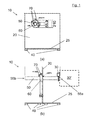
- the test apparatus 10 includes a cantilever plate 20 supported on a base sheet 25.
- the base sheet 25 is mounted on a plurality of isolation mounts 40, which act to isolate the plate 20 from environmental vibrations, to improve the accuracy of the testing.
- the cantilever plate 20 is coupled with a pipe 50 having its axis perpendicular to the plate 20.
- the pipe 50 is free at both of its ends 55a, 55b.
- the pipe 50 passes through a hole in the plate 20, the hole being off-centre, offset towards the top and side of the plate 20.
- An active vibration suppressor including a moveable collar 60 is mounted on the pipe 50, on the side of the plate 20 towards the left-hand end 55b of the pipe 50, as shown in Fig. 1(b) .
- the collar 60 was mounted so that it abutted the plate 20.
- the collar 60 carried a plurality of actuators 70.
- Vibrations were excited in the plate 20 and pipe 50 using a primary actuator (shaker) 30, mounted on the pipe 50, on the opposite side of the plate 20, close to the opposite end 55a of the pipe 50.
- This shaker 30 was used to excite vibrations representing the vibrations that would be excited by a machine 30' connected to the end 55a of the pipe 50.
- the collar 60 and actuators 70 are shown in more detail in Fig. 2 .
- the collar 60 is a steel annulus 80, approximately 20 cm in diameter with a central circular hole 9 cm in diameter.
- the annulus 80 is of rectangular cross-section, having flat front and rear surfaces and flat inner and outer walls.
- Five actuators 70a-e are mounted on the annulus 80: three are mounted on the front surface and two on the outer wall.
- the three actuators 70a-c mounted on the front surface of the annulus 80 are spaced equidistantly around the annulus, i.e. separated by 120 degrees. These three actuators 70a-c act in a direction perpendicular to the plane of the annulus 80, i.e. parallel to the axis of the pipe 50 when the collar is in use.
- the other two actuators 70d,e, mounted on the outer wall of the annulus act in directions perpendicular to the plane of the annulus 80 and perpendicular to each other.
- the three actuators 70a-c on the front surface, on the one hand, and the two actuators 70d,e on the outer wall on the other hand together provide actuation in three orthogonal directions.
- a feed-forward control strategy was selected to minimise the power input into the plate, using multiple actuators located on the plate, adjacent to and surrounding the beam.
- Three control forces were provided in the z direction (parallel to the pipe) and two control forces along the x and y directions.
- Fig. 3 shows the power input into the plate without control (black line), when the controller is optimised to minimise the power input into the plate at each frequency when only three vertical forces are used (dashed line), and when five control forces (three vertical and two horizontal) are used (dotted line).
- the best reduction of the power input into the plate is obtained at low frequency when the wavelength is much bigger than the distance between the secondary sources and the intersection point between the plate and the beam.
- the plot shows that the use of two extra control forces in x and y directions allows the system to achieve some control even at the in-plane resonance frequency of 1800 Hz.
- the actuators were located in the model on the beam at 3 cm from the plate, on the unexcited side of the beam.
- the model included three error sensors placed on the plate 20, around the pipe 50. The distance between the axis of the pipe 20 and the error sensor was 20 cm. There were also five monitoring sensors positioned on the plate 20, which could measure the velocity along the z-axis only (this constraint was used to represent the experimental facility). The purpose of the monitoring sensors was to obtain an indication of the global response of the plate 20 when control is applied.
- Fig. 4 shows the modelled power input into the plate without control (solid line), when the optimal controller that minimises the power input into the plate is implemented (dashed line) and when the sum of the velocities squared measured by three error sensors is minimised (dotted line).
- the three error sensors are able to measure the velocity along the three principal axis x, y, and z.
- Figure 4 shows that minimising the sum of the mean squared velocities measured by the three error sensors closely corresponds to the minimisation of the power input of the plate at low frequency, although at higher frequency less reduction in the power input into the plate is obtained in this example when the sum of the mean squared velocities is minimised.
- the second configuration simulates a vertical force along the z-axis (i.e. along the pipe 50) and two moments around the x- and y-axes acting on the pipe 50.
- Fig. 5 shows the modelled power input into the plate without control (solid line), when the optimal controller that minimises the power input into the plate is implemented (dashed line) and when the sum of the velocities squared measured by three error sensors is minimised (dotted line).
- the plot shows that in this case the two control strategies give very similar reduction in the power input into the plate.
- a vastly superior reduction compared with the previous case of three secondary forces was achieved.
- the two peaks that appear around 1.2 and 1.8 kHz are due to flexural vibration of the beam.
- Fig. 6 shows the sum of the mean squared velocities measured by the five monitoring sensors without control (solid line), when the power input into the plate is minimised (dashed line), and when the mean squared velocity measured by the three errors sensors is minimised (dotted line).
- the plot shows that excellent overall reduction in the vibration of the plate can be achieved using both control strategies up to about 1.8 kHz.
- the five actuators 70a-e on the collar 60 are each inertial electromagnetic actuators. As discussed above, actuators 70a-c generate a force perpendicular to the plate 20 while actuators 70d and 70e produce forces along the other two principal directions.
- the collar 60 can be rotated and moved along the pipe 50; however, in the experimental results presented below the collar 60 is positioned as close as possible to the plate 20.
- three accelerometers (not shown) are used as error sensors for control purposes; they are able to measure the acceleration along the three principal axes.
- Four single axis accelerometers were also placed on the plate 20 in order to monitor the global response.
- the primary disturbance excitation was provided using a Data Physics IV 40 inertial actuator (shaker) 30 located near the tip 55a of the pipe 50. That primary shaker 30 is also mounted on a collar which enables a variety of disturbances to be effected, by mounting the shaker 30 in different orientations.
- a Data Physics IV 40 inertial actuator (shaker) 30 located near the tip 55a of the pipe 50. That primary shaker 30 is also mounted on a collar which enables a variety of disturbances to be effected, by mounting the shaker 30 in different orientations.
- the transfer functions from, on the one hand, the primary source 30 and the actuators 70 to, on the other hand, all the sensors mounted on the plate 20 were measured. Those measured transfer functions were then used in further simulations to predict the behaviour of the system when different harmonic control strategies were implemented. The measured transfer functions were also used for the identification of the system required to implement real time control. All the transfer functions between the primary actuator 30 and secondary actuators 70 and the error and monitor sensors were measured using a twenty channel analyser (Data Physics Mobilyzer II). Although the transfer functions between the primary shaker 30 and the sensors have been measured for 4 different orientations of the primary actuator, only the results when the primary force forms an angle of about 45 degrees with each of the principal axis are presented here.
- Fig. 7 shows the modelled sum of the mean squared monitor velocities (plot (a)) and error velocities (plot (b)) without control (solid line) and when the optimal simulated control is implemented (dashed line).
- actuators 70a-c were driven with the same signal to minimise the sum of the three mean squared velocities measured by the three error sensors along z-axis.
- Actuators 70d,e were driven with two different signals to minimise the sum of the mean squared velocities in x- and y-axes respectively.
- the controller 75 applies three orthogonal forces aligned with the principal axes near the point of intersection of the pipe 50 and plate 20 and so is not able to produce moments to control vibration arising from this mode of excitation. Nevertheless, the plots show that significant reduction in excess of 40dB across a broad range of frequencies can be achieved by implementing this type of control.
- the resonance of the primary shaker is about 30 Hz, therefore at lower frequencies the structure cannot be efficiently excited.
- the resonance of the secondary actuators 70 is about 55 Hz therefore control will not be effective at frequencies significantly below this.
- FIG. 8 shows the modelled sum of the mean squared monitor velocities (plot (a)) and error velocities (plot (b)) without control (solid line) and when the optimal simulated control is implemented (dashed line).
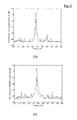
- Fig. 9 (a)-(c) shows the PSD of the sum of the accelerations measured by the three error sensors along x, y and z-axis respectively without control (blue line) and with control (red line).
- An iterative frequency domain algorithm was used for the control strategy; however, in the time available a rigorous search for the optimal parameters was not possible and so these results do not represent the true optimum performance for this configuration. Nevertheless, and despite the limited control authority, the plots show that the error signals at the excitation frequency of 447 Hz are reduced by 17.3, 17.2 and 32.5 dB respectively. That clearly demonstrates the validity of the theoretical results above and underlines the enormous potential of the approach.
Landscapes
- Engineering & Computer Science (AREA)
- General Engineering & Computer Science (AREA)
- Physics & Mathematics (AREA)
- Mechanical Engineering (AREA)
- Acoustics & Sound (AREA)
- Aviation & Aerospace Engineering (AREA)
- Electromagnetism (AREA)
- Vibration Prevention Devices (AREA)
Priority Applications (9)
| Application Number | Priority Date | Filing Date | Title |
|---|---|---|---|
| EP20130275162 EP2824360A1 (de) | 2013-07-12 | 2013-07-12 | Verbesserungen an und in Zusammenhang mit Vibrationssteuerung |
| US14/903,798 US9915312B2 (en) | 2013-07-12 | 2014-07-02 | Vibration control |
| ES14736930.0T ES2628241T3 (es) | 2013-07-12 | 2014-07-02 | Mejoras en el control de vibraciones y relacionadas con este |
| PCT/GB2014/052002 WO2015004425A1 (en) | 2013-07-12 | 2014-07-02 | Improvements in and relating to vibration control |
| EP14736930.0A EP3019768B1 (de) | 2013-07-12 | 2014-07-02 | Verbesserungen an und in zusammenhang mit vibrationssteuerung |
| AU2014288996A AU2014288996B2 (en) | 2013-07-12 | 2014-07-02 | Improvements in and relating to vibration control |
| JP2016524889A JP6219513B2 (ja) | 2013-07-12 | 2014-07-02 | 振動制御における、および、振動制御に関連した改良 |
| CA2917786A CA2917786C (en) | 2013-07-12 | 2014-07-02 | Improvements in and relating to vibration control |
| US15/883,549 US10167917B2 (en) | 2013-07-12 | 2018-01-30 | Vibration control |
Applications Claiming Priority (1)
| Application Number | Priority Date | Filing Date | Title |
|---|---|---|---|
| EP20130275162 EP2824360A1 (de) | 2013-07-12 | 2013-07-12 | Verbesserungen an und in Zusammenhang mit Vibrationssteuerung |
Publications (1)
| Publication Number | Publication Date |
|---|---|
| EP2824360A1 true EP2824360A1 (de) | 2015-01-14 |
Family
ID=48793133
Family Applications (1)
| Application Number | Title | Priority Date | Filing Date |
|---|---|---|---|
| EP20130275162 Ceased EP2824360A1 (de) | 2013-07-12 | 2013-07-12 | Verbesserungen an und in Zusammenhang mit Vibrationssteuerung |
Country Status (1)
| Country | Link |
|---|---|
| EP (1) | EP2824360A1 (de) |
Citations (17)
| Publication number | Priority date | Publication date | Assignee | Title |
|---|---|---|---|---|
| US1819665A (en) * | 1930-01-08 | 1931-08-18 | Vibrachek Company | Vibration reducing device |
| US4282938A (en) * | 1978-03-25 | 1981-08-11 | Yokosuka Boat Kabushiki Kaisha | Vibration insulation device for handle of vibratory machine |
| JPS5950243A (ja) * | 1982-09-16 | 1984-03-23 | Nippon Kokan Kk <Nkk> | 動吸振器 |
| JPH04281870A (ja) * | 1991-03-12 | 1992-10-07 | Toshiba Corp | 遠心分離機 |
| JPH0518437A (ja) * | 1991-07-10 | 1993-01-26 | Hitachi Plant Eng & Constr Co Ltd | 除振装置 |
| JPH0526291A (ja) * | 1991-04-05 | 1993-02-02 | Yoshihiko Sugiyama | 流体を用いた構造物の安定化方法 |
| JPH05172183A (ja) * | 1991-12-24 | 1993-07-09 | Ando Kensetsu Kk | 構造物の除振装置 |
| EP0552695A1 (de) * | 1992-01-21 | 1993-07-28 | ALENIA AERITALIA & SELENIA S.P.A. | Dynamischer zwei frequenzdämpfer |
| US5251863A (en) * | 1992-08-12 | 1993-10-12 | Noise Cancellation Technologies, Inc. | Active force cancellation system |
| JPH07113438A (ja) * | 1993-10-14 | 1995-05-02 | Murata Mach Ltd | 動吸振器 |
| US5845236A (en) * | 1996-10-16 | 1998-12-01 | Lord Corporation | Hybrid active-passive noise and vibration control system for aircraft |
| US5883447A (en) * | 1995-02-03 | 1999-03-16 | Mesure Et Informatique Mei | Vibration damping devices with active control and comprising movable weights excited by electromagnets along 2 or 3 axes |
| JP2003278830A (ja) * | 2002-01-15 | 2003-10-02 | Mitsubishi Heavy Ind Ltd | 回転体安定化装置 |
| DE102007015634A1 (de) * | 2007-03-31 | 2008-10-02 | Schaeffler Kg | Dämpfungseinrichtung zum Dämpfen von Querschwingungen einer Welle oder dergleichen |
| JP2008265379A (ja) * | 2007-04-16 | 2008-11-06 | Yanmar Co Ltd | 作業車両 |
| US20090023571A1 (en) * | 2006-09-01 | 2009-01-22 | Shoji Kusumoto | Centrifugal machine |
| JP2009091859A (ja) * | 2007-10-12 | 2009-04-30 | Bridgestone Corp | 床支持具及び床構造 |
-
2013
- 2013-07-12 EP EP20130275162 patent/EP2824360A1/de not_active Ceased
Patent Citations (17)
| Publication number | Priority date | Publication date | Assignee | Title |
|---|---|---|---|---|
| US1819665A (en) * | 1930-01-08 | 1931-08-18 | Vibrachek Company | Vibration reducing device |
| US4282938A (en) * | 1978-03-25 | 1981-08-11 | Yokosuka Boat Kabushiki Kaisha | Vibration insulation device for handle of vibratory machine |
| JPS5950243A (ja) * | 1982-09-16 | 1984-03-23 | Nippon Kokan Kk <Nkk> | 動吸振器 |
| JPH04281870A (ja) * | 1991-03-12 | 1992-10-07 | Toshiba Corp | 遠心分離機 |
| JPH0526291A (ja) * | 1991-04-05 | 1993-02-02 | Yoshihiko Sugiyama | 流体を用いた構造物の安定化方法 |
| JPH0518437A (ja) * | 1991-07-10 | 1993-01-26 | Hitachi Plant Eng & Constr Co Ltd | 除振装置 |
| JPH05172183A (ja) * | 1991-12-24 | 1993-07-09 | Ando Kensetsu Kk | 構造物の除振装置 |
| EP0552695A1 (de) * | 1992-01-21 | 1993-07-28 | ALENIA AERITALIA & SELENIA S.P.A. | Dynamischer zwei frequenzdämpfer |
| US5251863A (en) * | 1992-08-12 | 1993-10-12 | Noise Cancellation Technologies, Inc. | Active force cancellation system |
| JPH07113438A (ja) * | 1993-10-14 | 1995-05-02 | Murata Mach Ltd | 動吸振器 |
| US5883447A (en) * | 1995-02-03 | 1999-03-16 | Mesure Et Informatique Mei | Vibration damping devices with active control and comprising movable weights excited by electromagnets along 2 or 3 axes |
| US5845236A (en) * | 1996-10-16 | 1998-12-01 | Lord Corporation | Hybrid active-passive noise and vibration control system for aircraft |
| JP2003278830A (ja) * | 2002-01-15 | 2003-10-02 | Mitsubishi Heavy Ind Ltd | 回転体安定化装置 |
| US20090023571A1 (en) * | 2006-09-01 | 2009-01-22 | Shoji Kusumoto | Centrifugal machine |
| DE102007015634A1 (de) * | 2007-03-31 | 2008-10-02 | Schaeffler Kg | Dämpfungseinrichtung zum Dämpfen von Querschwingungen einer Welle oder dergleichen |
| JP2008265379A (ja) * | 2007-04-16 | 2008-11-06 | Yanmar Co Ltd | 作業車両 |
| JP2009091859A (ja) * | 2007-10-12 | 2009-04-30 | Bridgestone Corp | 床支持具及び床構造 |
Similar Documents
| Publication | Publication Date | Title |
|---|---|---|
| Cazzolato | Sensing systems for active control of sound transmission into cavities | |
| US10167917B2 (en) | Vibration control | |
| Lacour et al. | Preliminary experiments on noise reduction in cavities using active impedance changes | |
| Winberg et al. | Active control of engine vibrations in a Collins class submarine | |
| EP2824360A1 (de) | Verbesserungen an und in Zusammenhang mit Vibrationssteuerung | |
| Johnson et al. | The effect of actuator and sensor placement on the active control of rotor unbalance | |
| Moro | Structure borne noise due to marine diesel engines: experimental study and numerical simulation for the prediction of the dynamic behaviour of resilient mounts | |
| GB2516102A (en) | Improvements in and relating to vibration control | |
| Smith et al. | Experiments on the active control of inlet noise from a turbofan jet engine using multiple circumferential control arrays | |
| Wang et al. | Comprehensive investigation on active-passive hybrid isolation and tunable dynamic vibration absorption | |
| Gibbs et al. | The characterization of structure-borne emission of building services machinery using the source descriptor concept | |
| Tewes | Active trim panel attachments for control of sound transmission through aircraft structures | |
| Kokott et al. | Investigation towards an active barrier for structure borne sound using structural intensity | |
| Yun et al. | Power transmission from two coherent machines to a dual-layer coupling floor structure | |
| Xiong et al. | Experiment and analysis of active vibration isolation system based on rigid pedestal using SDOF actuator | |
| Zhang et al. | The fast prediction of sound radiation from typical submarine cabin based on acoustic transfer vector | |
| Liu et al. | The Design and Analysis of Active–Passive Hybrid Vibration Isolation Mounts Applied in Pump | |
| Wang et al. | An error-sensor location Scheme in Active Vibration Isolation Based on Elastic Foundation | |
| He et al. | A Two-Dimensional Hybrid Computational Acoustics Method to Predict the Far-Field Noises | |
| Aucejo et al. | Source Scanning Technique for simulating TBL-induced vibrations measurements | |
| Blanchet et al. | Prediction of Underwater Radiated Noise caused by Airborne Noise: Empirical vs. SEA | |
| Allam et al. | Investigation of Installation Effects for an Axial Fan | |
| Fahy et al. | Proceedings of the Second International Congress on Recent Developments in Air-and Structure-Borne Sound and Vibration (2nd) Held in Auburn University, Alabama on 4-6 March 1992. Volume 2 | |
| Bettarello et al. | The use of sustainable sound absorbing foam recycling microplastics in sound insulation | |
| Allam et al. | Investigation of aerodynamic installation effects for an axial fan |
Legal Events
| Date | Code | Title | Description |
|---|---|---|---|
| 17P | Request for examination filed |
Effective date: 20130712 |
|
| AK | Designated contracting states |
Kind code of ref document: A1 Designated state(s): AL AT BE BG CH CY CZ DE DK EE ES FI FR GB GR HR HU IE IS IT LI LT LU LV MC MK MT NL NO PL PT RO RS SE SI SK SM TR |
|
| AX | Request for extension of the european patent |
Extension state: BA ME |
|
| PUAI | Public reference made under article 153(3) epc to a published international application that has entered the european phase |
Free format text: ORIGINAL CODE: 0009012 |
|
| STAA | Information on the status of an ep patent application or granted ep patent |
Free format text: STATUS: THE APPLICATION HAS BEEN REFUSED |
|
| 18R | Application refused |
Effective date: 20150309 |