EP3019768B1 - Verbesserungen an und in zusammenhang mit vibrationssteuerung - Google Patents
Verbesserungen an und in zusammenhang mit vibrationssteuerung Download PDFInfo
- Publication number
- EP3019768B1 EP3019768B1 EP14736930.0A EP14736930A EP3019768B1 EP 3019768 B1 EP3019768 B1 EP 3019768B1 EP 14736930 A EP14736930 A EP 14736930A EP 3019768 B1 EP3019768 B1 EP 3019768B1
- Authority
- EP
- European Patent Office
- Prior art keywords
- plate
- rod
- machine
- actuators
- vibrations
- Prior art date
- Legal status (The legal status is an assumption and is not a legal conclusion. Google has not performed a legal analysis and makes no representation as to the accuracy of the status listed.)
- Active
Links
Images





Classifications
-
- F—MECHANICAL ENGINEERING; LIGHTING; HEATING; WEAPONS; BLASTING
- F16—ENGINEERING ELEMENTS AND UNITS; GENERAL MEASURES FOR PRODUCING AND MAINTAINING EFFECTIVE FUNCTIONING OF MACHINES OR INSTALLATIONS; THERMAL INSULATION IN GENERAL
- F16F—SPRINGS; SHOCK-ABSORBERS; MEANS FOR DAMPING VIBRATION
- F16F7/00—Vibration-dampers; Shock-absorbers
- F16F7/10—Vibration-dampers; Shock-absorbers using inertia effect
- F16F7/1005—Vibration-dampers; Shock-absorbers using inertia effect characterised by active control of the mass
-
- F—MECHANICAL ENGINEERING; LIGHTING; HEATING; WEAPONS; BLASTING
- F16—ENGINEERING ELEMENTS AND UNITS; GENERAL MEASURES FOR PRODUCING AND MAINTAINING EFFECTIVE FUNCTIONING OF MACHINES OR INSTALLATIONS; THERMAL INSULATION IN GENERAL
- F16F—SPRINGS; SHOCK-ABSORBERS; MEANS FOR DAMPING VIBRATION
- F16F15/00—Suppression of vibrations in systems; Means or arrangements for avoiding or reducing out-of-balance forces, e.g. due to motion
- F16F15/005—Suppression of vibrations in systems; Means or arrangements for avoiding or reducing out-of-balance forces, e.g. due to motion using electro- or magnetostrictive actuation means
-
- F—MECHANICAL ENGINEERING; LIGHTING; HEATING; WEAPONS; BLASTING
- F16—ENGINEERING ELEMENTS AND UNITS; GENERAL MEASURES FOR PRODUCING AND MAINTAINING EFFECTIVE FUNCTIONING OF MACHINES OR INSTALLATIONS; THERMAL INSULATION IN GENERAL
- F16F—SPRINGS; SHOCK-ABSORBERS; MEANS FOR DAMPING VIBRATION
- F16F15/00—Suppression of vibrations in systems; Means or arrangements for avoiding or reducing out-of-balance forces, e.g. due to motion
- F16F15/02—Suppression of vibrations of non-rotating, e.g. reciprocating systems; Suppression of vibrations of rotating systems by use of members not moving with the rotating systems
-
- F—MECHANICAL ENGINEERING; LIGHTING; HEATING; WEAPONS; BLASTING
- F16—ENGINEERING ELEMENTS AND UNITS; GENERAL MEASURES FOR PRODUCING AND MAINTAINING EFFECTIVE FUNCTIONING OF MACHINES OR INSTALLATIONS; THERMAL INSULATION IN GENERAL
- F16F—SPRINGS; SHOCK-ABSORBERS; MEANS FOR DAMPING VIBRATION
- F16F15/00—Suppression of vibrations in systems; Means or arrangements for avoiding or reducing out-of-balance forces, e.g. due to motion
- F16F15/02—Suppression of vibrations of non-rotating, e.g. reciprocating systems; Suppression of vibrations of rotating systems by use of members not moving with the rotating systems
- F16F15/03—Suppression of vibrations of non-rotating, e.g. reciprocating systems; Suppression of vibrations of rotating systems by use of members not moving with the rotating systems using magnetic or electromagnetic means
-
- F—MECHANICAL ENGINEERING; LIGHTING; HEATING; WEAPONS; BLASTING
- F16—ENGINEERING ELEMENTS AND UNITS; GENERAL MEASURES FOR PRODUCING AND MAINTAINING EFFECTIVE FUNCTIONING OF MACHINES OR INSTALLATIONS; THERMAL INSULATION IN GENERAL
- F16F—SPRINGS; SHOCK-ABSORBERS; MEANS FOR DAMPING VIBRATION
- F16F7/00—Vibration-dampers; Shock-absorbers
- F16F7/10—Vibration-dampers; Shock-absorbers using inertia effect
- F16F7/1005—Vibration-dampers; Shock-absorbers using inertia effect characterised by active control of the mass
- F16F7/1011—Vibration-dampers; Shock-absorbers using inertia effect characterised by active control of the mass by electromagnetic means
Definitions
- This invention relates to the field of vibration control. More particularly, the invention relates to active suppression of vibrations caused by machinery. Still more particularly, but not exclusively, the invention relates to active suppression of vibrations in vehicles, for example nautical vessels.
- ADD.Pipe active absorber
- Vibrations in such systems are typically caused by water or other liquid hammers, pressure pulses or other excitations.
- the ADD.Pipe system is a collar that is clamped onto the piping system and includes a sensor that measures vibrations in the pipe and linear actuators actively controlled to move reaction masses to damp the vibrations in the pipe.
- the system offers only limited control, and has the potential to suffer from an effect known as pinning, in which vibration at the point of attachment of the collar is reduced but becomes worse at points elsewhere in the pipeline.
- JPH0526291 describes a rubber tube being a structure that is supported in a cantilever form state.
- a control signal to a control valve is outputted from a valve operation signal generating device.
- a valve is released and a given amount of an air flow from a compressed air tank flows in from the fixed end of the rubber tube.
- a damping action is exerted on the rubber tube by a Colioris force and the amplitude of a free end is gradually decreased.
- the decrease of vibration amplitude is detected by a non-contact displacement gage, a displacement signal therefrom is inputted to a valve operation signal generator, and a control signal is changed.
- the opening of the valve is freely controlled according to an amplitude amount of the free end of the rubber tube and when the amplitude amount is below a specified value, the air flow is stopped.
- This constitution produces a smooth damping effect without damaging the rubber tube.
- JPH04281870 describes a separating container body provided pendently on a stand having an earthquake detector and a bearing housing is provided on a plummer block of the stand.
- a revolving shaft is freely rotatably fitted in cantilever to this bearing housing through the stand into a separating container body.
- a separating container is journaled to this revolving shaft and a vibration damping spring and the magnetic fluid damper are interposed between the plummer block and the bearing housing.
- the electromagnet is connected to this magnetic fluid damper directly or indirectly to the earthquake detector and is so provided as to be energized at the time of the earthquakes. Consequently, the electromagnet is energized and excited in accordance with the signal from the earthquake detector, by which the magnetic fluid of the magnetic fluid damper is energized and the vibration is damped.
- JPS5950243 describes a support lever, in the form of a long rod which is cantilever-mounted to a hull, attached in a flexible manner at its one end in a pre-determined position through a support bracket, and a spring is installed inbetween the hull to allow the support lever to vibrate.
- a weight which is mounted on the support lever and is capable of changing its natural frequency k2 in response to the change in the distance from the point of support, is moved by a motor through a screw thread mechanism.
- JPH07113438 describes a dynamic vibration absorbing device where a weight is mounted on a vibrating body through spring means so as to absorb vibration of a vibrating body, the means is composed of a support shaft projected in a cantilever form from a mounting frame and the weight is fitted to the shaft so as to move in the axial direction.
- a first aspect of the invention provides an apparatus including a machine, a rod and a plate, wherein the machine is on a first side of the plate and at least part of the rod is on the second, opposite, side of the plate, and wherein the plate is susceptible to vibrations arising from operation of the machine, the apparatus including an active vibration suppressor mounted on the rod, and a controller configured to control the active vibration suppressor to reduce vibrations of the plate characterised in that the rod passes through the plate, from the first side of the plate to the second side of the plate.
- the machine is a source of motive force, for example an engine, for example an internal combustion engine, an electric motor or a turbine.
- the rod is connected, for example directly connected, to the machine. It may be that the rod is driven by the machine. It may be that the rod is also susceptible to vibrations arising from operation of the machine.
- the rod is a pipe. It may be that the rod is a cable or a bundle of cables. It may be that the rod is connected to or associated with the machine, for example it may be a pipe carrying a fluid to or from the machine (for example, fuel, coolant or exhaust) or a conduit carrying for example electrical power couplings.
- the rod is flexible. Alternatively, it may be that the rod is rigid.
- the plate is a flat plate. It may be that the plate is a curved plate.
- the plate is a shell or a wall or a bulkhead.
- the plate is or is part of a housing containing the machine.
- the housing may, for example, be a cuboidal housing, or a dome-shaped housing, or have another or a more complex shape. It may be that the plate forms part of a wall of the housing: the first side of the plate will then be inside the housing and the second side of the plate will be outside the housing.
- the plate is part of the machine itself, or is directly connected to the machine.
- rod or at least part of the rod is perpendicular to the plate.
- the rod is rigidly connected to the plate.
- the rod is resiliently connected to the plate
- the rod is formed from a first part on the first side of the plate and a second part on the second side of the plate, such that the first and second parts meet at the plate and are connected to each other and/or to the plate.
- the active vibration suppressor is mounted on the rod on the second side of the plate, i.e. the opposite side from the machine.
- the active vibration suppressor includes a collar that is connected to and at least partially surrounds the circumference of the rod. It may be that the collar completely surrounds the circumference of the rod. It may be that the collar is integrated with the rod (i.e. they are monolithic). It may be that the collar is permanently fixed to the rod. It may be that the collar is releasably fixed to the rod. It may be that the collar is moveable on the rod. It may be that the collar is positioned immediately adjacent to the plate.
- the active vibration suppressor comprises a plurality of (for example 5) actuators arranged to act on the rod. It may be that the actuators act on the rod directly or it may be that the actuators act on the rod indirectly, for example through the collar, if present. It may be that at least one of the actuators is arranged to act in a direction parallel to the length of the rod. It may be that there are three actuators, arranged to act on the rod in three orthogonal directions. It may be that two or more of the plurality of the actuators are arranged to act on the rod the same direction, for example in a direction parallel to the length of the rod.
- the plurality of actuators includes one or more actuators arranged to apply a bending moment to the rod. It may be that the plurality of actuators includes two or more actuators arranged to apply orthogonal bending moments to the rod.
- the plurality of actuators includes one or more actuators arranged to apply radial forces to induce compression in the rod;
- the rod may be a pipe arranged to carry a flow and the controller may be configured to control that one or more actuator to suppress flow noise in the pipe.
- the actuators may be magnetostrictive actuators.
- the actuators may be voice-coil activators.
- the actuators may be piezo-electric devices.
- the apparatus may further comprises a plurality of sensors arranged to sense vibrations of the plate and to generate a signal indicative of those vibrations.
- the sensors may for example measure the velocity of the plate at the location of the sensor.
- the controller may be configured to receive the generated signal and to use it to determine a control signal to be generated and applied to the actuators to suppress vibrations of the plate.
- the controller may be configured to suppress vibrations of the plate by minimising a parameter derived from the signal from the sensors, for example minimising the sum of mean squared velocities measured by the sensors.
- the controller may be configured to control three degrees of freedom of movement of the plate, for example movement in three orthogonal directions, two in the plane of the plate and the third perpendicular to the plate, or one perpendicular to the plate and moments about two perpendicular axes in the plane of the plate.
- the controller may be configured to control five degrees of freedom of movement of the plate, for example movement in three orthogonal directions, two in the plane of the plate and the third perpendicular to the plate, and moments about two perpendicular axes in the plane of the plate. It may be that there is the same number of actuators as there are degrees of freedom of movement controlled by the controller.
- the controller is configured to control the active vibration suppressor also to reduce vibrations of a further part of the apparatus, for example a part of the rod or another rod included in the apparatus.
- the apparatus may then further comprise a plurality of sensors arranged to sense vibrations of the further part of the apparatus and to generate a signal indicative of those vibrations.
- the sensors may for example measure the velocity of the further part at the location of the sensor.
- the controller may be configured to receive the generated signal and to use it to determine a control signal to be generated and applied to the actuators to suppress vibrations of the further part.
- the controller may be configured to suppress vibrations of the further part by minimising a parameter derived from the signal from the sensors, for example minimising the sum of mean squared velocities measured by the sensors.
- the controller may be configured to control three degrees of freedom of movement of the further part, for example movement in three orthogonal directions.
- the controller may be configured to control five degrees of freedom of movement of the further part, for example movement in three orthogonal directions and moments about two perpendicular axes. It may be that there is the same number of actuators as there are degrees of freedom of movement controlled by the controller.
- a second aspect of the invention provides a method of suppressing vibrations arising from operation of a machine, wherein the machine is part of an apparatus also including a rod and a plate, the machine being on a first side of the plate and at least part of the rod being on the second, opposite, side of the plate, the plate being susceptible to vibrations arising from operation of the machine, the method comprising applying an actively controlled force to the rod to reduce vibrations of the plate, characterised in that the rod passes through the plate, from the first side of the plate to the second side of the plate.
- the test apparatus 10 includes a cantilever plate 20 supported on a base sheet 25.
- the base sheet 25 is mounted on a plurality of isolation mounts 40, which act to isolate the plate 20 from environmental vibrations, to improve the accuracy of the testing.
- the cantilever plate 20 is coupled with a pipe 50 having its axis perpendicular to the plate 20.
- the pipe 50 is free at both of its ends 55a, 55b.
- the pipe 50 passes through a hole in the plate 20, the hole being off-centre, offset towards the top and side of the plate 20.
- An active vibration suppressor including a moveable collar 60 is mounted on the pipe 50, on the side of the plate 20 towards the left-hand end 55b of the pipe 50, as shown in Fig. 1(b) .
- the collar 60 was mounted so that it abutted the plate 20.
- the collar 60 carried a plurality of actuators 70.
- Vibrations were excited in the plate 20 and pipe 50 using a primary actuator (shaker) 30, mounted on the pipe 50, on the opposite side of the plate 20, close to the opposite end 55a of the pipe 50.
- This shaker 30 was used to excite vibrations representing the vibrations that would be excited by a machine 30' connected to the end 55a of the pipe 50.
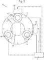
- the collar 60 and actuators 70 are shown in more detail in Fig. 2 .
- the collar 60 is a steel annulus 80, approximately 20 cm in diameter with a central circular hole 9 cm in diameter.
- the annulus 80 is of rectangular cross-section, having flat front and rear surfaces and flat inner and outer walls.
- Five actuators 70a-e are mounted on the annulus 80: three are mounted on the front surface and two on the outer wall.
- the three actuators 70a-c mounted on the front surface of the annulus 80 are spaced equidistantly around the annulus, i.e. separated by 120 degrees. These three actuators 70a-c act in a direction perpendicular to the plane of the annulus 80, i.e. parallel to the axis of the pipe 50 when the collar is in use.
- the other two actuators 70d,e, mounted on the outer wall of the annulus act in directions perpendicular to the plane of the annulus 80 and perpendicular to each other.
- the three actuators 70a-c on the front surface, on the one hand, and the two actuators 70d,e on the outer wall on the other hand together provide actuation in three orthogonal directions.
- a feed-forward control strategy was selected to minimise the power input into the plate, using multiple actuators located on the plate, adjacent to and surrounding the beam.
- Three control forces were provided in the z direction (parallel to the pipe) and two control forces along the x and y directions.
- Fig. 3 shows the power input into the plate without control (black line), when the controller is optimised to minimise the power input into the plate at each frequency when only three vertical forces are used (dashed line), and when five control forces (three vertical and two horizontal) are used (dotted line).
- the best reduction of the power input into the plate is obtained at low frequency when the wavelength is much bigger than the distance between the secondary sources and the intersection point between the plate and the beam.
- the plot shows that the use of two extra control forces in x and y directions allows the system to achieve some control even at the in-plane resonance frequency of 1800 Hz.
- the actuators were located in the model on the beam at 3 cm from the plate, on the unexcited side of the beam.
- the model included three error sensors placed on the plate 20, around the pipe 50. The distance between the axis of the pipe 20 and the error sensor was 20 cm. There were also five monitoring sensors positioned on the plate 20, which could measure the velocity along the z-axis only (this constraint was used to represent the experimental facility). The purpose of the monitoring sensors was to obtain an indication of the global response of the plate 20 when control is applied.
- Fig. 4 shows the modelled power input into the plate without control (solid line), when the optimal controller that minimises the power input into the plate is implemented (dashed line) and when the sum of the velocities squared measured by three error sensors is minimised (dotted line).
- the three error sensors are able to measure the velocity along the three principal axis x, y, and z.
- Figure 4 shows that minimising the sum of the mean squared velocities measured by the three error sensors closely corresponds to the minimisation of the power input of the plate at low frequency, although at higher frequency less reduction in the power input into the plate is obtained in this example when the sum of the mean squared velocities is minimised.
- the second configuration simulates a vertical force along the z-axis (i.e. along the pipe 50) and two moments around the x- and y-axes acting on the pipe 50.
- Fig. 5 shows the modelled power input into the plate without control (solid line), when the optimal controller that minimises the power input into the plate is implemented (dashed line) and when the sum of the velocities squared measured by three error sensors is minimised (dotted line).
- the plot shows that in this case the two control strategies give very similar reduction in the power input into the plate.
- a vastly superior reduction compared with the previous case of three secondary forces was achieved.
- the two peaks that appear around 1.2 and 1.8 kHz are due to flexural vibration of the beam.
- Fig. 6 shows the sum of the mean squared velocities measured by the five monitoring sensors without control (solid line), when the power input into the plate is minimised (dashed line), and when the mean squared velocity measured by the three errors sensors is minimised (dotted line).
- the plot shows that excellent overall reduction in the vibration of the plate can be achieved using both control strategies up to about 1.8 kHz.
- the five actuators 70a-e on the collar 60 are each inertial electromagnetic actuators. As discussed above, actuators 70a-c generate a force perpendicular to the plate 20 while actuators 70d and 70e produce forces along the other two principal directions.
- the collar 60 can be rotated and moved along the pipe 50; however, in the experimental results presented below the collar 60 is positioned as close as possible to the plate 20.
- three accelerometers (not shown) are used as error sensors for control purposes; they are able to measure the acceleration along the three principal axes.
- Four single axis accelerometers were also placed on the plate 20 in order to monitor the global response.
- the primary disturbance excitation was provided using a Data Physics IV 40 inertial actuator (shaker) 30 located near the tip 55a of the pipe 50. That primary shaker 30 is also mounted on a collar which enables a variety of disturbances to be effected, by mounting the shaker 30 in different orientations.
- a Data Physics IV 40 inertial actuator (shaker) 30 located near the tip 55a of the pipe 50. That primary shaker 30 is also mounted on a collar which enables a variety of disturbances to be effected, by mounting the shaker 30 in different orientations.
- the transfer functions from, on the one hand, the primary source (primary shaker) 30 and the actuators 70 to, on the other hand, all the sensors mounted on the plate 20 were measured. Those measured transfer functions were then used in further simulations to predict the behaviour of the system when different harmonic control strategies were implemented. The measured transfer functions were also used for the identification of the system required to implement real time control. All the transfer functions between the primary actuator 30 and secondary actuators 70 and the error and monitor sensors were measured using a twenty channel analyser (Data Physics Mobilyzer II). Although the transfer functions between the primary shaker 30 and the sensors have been measured for 4 different orientations of the primary actuator, only the results when the primary force forms an angle of about 45 degrees with each of the principal axis are presented here.
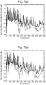
- Fig. 7 shows the modelled sum of the mean squared monitor velocities (plot (a)) and error velocities (plot (b)) without control (solid line) and when the optimal simulated control is implemented (dashed line).
- actuators 70a-c were driven with the same signal to minimise the sum of the three mean squared velocities measured by the three error sensors along z-axis.
- Actuators 70d,e were driven with two different signals to minimise the sum of the mean squared velocities in x- and y-axes respectively.
- the controller 75 applies three orthogonal forces aligned with the principal axes near the point of intersection of the pipe 50 and plate 20 and so is not able to produce moments to control vibration arising from this mode of excitation. Nevertheless, the plots show that significant reduction in excess of 40dB across a broad range of frequencies can be achieved by implementing this type of control.
- the resonance of the primary shaker is about 30 Hz, therefore at lower frequencies the structure cannot be efficiently excited.
- the resonance of the secondary actuators 70 is about 55 Hz therefore control will not be effective at frequencies significantly below this.
- FIG. 8 shows the modelled sum of the mean squared monitor velocities (plot (a)) and error velocities (plot (b)) without control (solid line) and when the optimal simulated control is implemented (dashed line).
- Fig. 9 (a)-(c) shows the PSD of the sum of the accelerations measured by the three error sensors along x, y and z-axis respectively without control (blue line) and with control (red line).
- An iterative frequency domain algorithm was used for the control strategy; however, in the time available a rigorous search for the optimal parameters was not possible and so these results do not represent the true optimum performance for this configuration. Nevertheless, and despite the limited control authority, the plots show that the error signals at the excitation frequency of 447 Hz are reduced by 17.3, 17.2 and 32.5 dB respectively. That clearly demonstrates the validity of the theoretical results above and underlines the enormous potential of the approach.
Landscapes
- Engineering & Computer Science (AREA)
- General Engineering & Computer Science (AREA)
- Physics & Mathematics (AREA)
- Mechanical Engineering (AREA)
- Acoustics & Sound (AREA)
- Aviation & Aerospace Engineering (AREA)
- Electromagnetism (AREA)
- Vibration Prevention Devices (AREA)
Claims (13)
- Gerät, welches eine Maschine (30'), eine Stange (50) und eine Platte (20) umfasst, wobei die Platte (20) mit der Stange (50) verbunden ist, wobei sich die Maschine (30') auf einer ersten Seite der Platte (20) befindet und wobei die Platte (20) und die Stange (50) anfällig für Vibrationen sind, welche beim Betrieb der Maschine (30') entstehen, wobei das Gerät einen aktiven, an der Stange montierten Vibrationsunterdrücker und eine Steuereinrichtung (75) umfasst, welche dafür ausgelegt ist, den aktiven Vibrationsunterdrücker zu steuern, um Vibrationen der Platte (20) zu reduzieren, dadurch gekennzeichnet, dass die Stange (50) durch ein Loch in der Platte (20) von der ersten Seite der Platte zu der zweiten, gegenüber liegenden Seite der Platte verläuft.
- Gerät nach Anspruch 1, wobei die Stange (20) mit der Maschine (30') verbunden ist.
- Gerät nach einem der vorhergehenden Ansprüche, wobei die Stange (50) ein Rohr ist.
- Gerät nach einem der vorhergehenden Ansprüche, wobei die Platte (20) ein Gehäuse oder Teil eines Gehäuses ist, welches die Maschine enthält.
- Gerät nach einem der Ansprüche 1 bis 3, wobei die Platte (20) Teil der Maschine (30') selbst ist oder direkt mit der Maschine (30') verbunden ist.
- Gerät nach einem der vorhergehenden Ansprüche, wobei der aktive Vibrationsunterdrücker an der Stange (50) auf der zweiten Seite der Platte (20) montiert ist.
- Gerät nach einem der vorhergehenden Ansprüche, wobei der aktive Vibrationsunterdrücker eine Vielzahl von Stellgliedern (70) aufweist, welche eingerichtet sind, um auf die Stange (50) einzuwirken.
- Gerät nach einem der vorhergehenden Ansprüche, wobei der aktive Vibrationsunterdrücker einen Kragen (60) umfasst, welcher mit dem Umfang der Stange (50) verbunden ist und diesen zumindest teilweise umgibt.
- Gerät nach Anspruch 8, wobei drei oder mehr Stellglieder (70 a-c) eingerichtet sind, um in einer Richtung parallel zu der Länge der Stange (50) zu wirken, indem sie auf eine erste Fläche des Kragens (60) einwirken, wobei die erste Fläche senkrecht zur Stange (50) verläuft, und zwei oder mehr Stellglieder (70 d, e) eingerichtet, um in zwei Richtungen zu wirken, senkrecht zu der Länge der Stange (50) und zueinander, indem sie auf den Kragen (60) auf eine Fläche senkrecht zu der ersten Fläche einwirken.
- Gerät nach einem der vorhergehenden Ansprüche, weiter aufweisend eine Vielzahl von Sensoren, welche eingerichtet sind, um Vibrationen der Platte zu erfassen und ein Signal zu erzeugen, welches diesen Vibrationen entspricht.
- Gerät nach Anspruch 10, wobei die Steuereinrichtung (75) dafür ausgelegt ist, Vibrationen der Platte (20) zu unterdrücken, indem ein von dem Signal der Sensoren abgeleiteter Parameter minimiert wird.
- Gerät nach Anspruch 11, wobei der Parameter die Summe von mittlerer quadratischer, von den Sensoren gemessenen Geschwindigkeiten ist.
- Verfahren zum Unterdrücken von Vibrationen, welche beim Betrieb der Maschine (30') entstehen, wobei die Maschine (30') Teil eines Geräts ist, welches auch eine Stange (50) und eine Platte (20) umfasst, wobei die Platte (20) mit der Stange (50) verbunden ist, wobei sich die Maschine (30') auf einer ersten Seite der Platte (20) befindet, wobei die Platte (20) und die Stange (50) anfällig für Vibrationen sind, welche beim Betrieb der Maschine (30') entstehen, wobei das Verfahren das Aufbringen einer aktiv gesteuerten Kraft auf die Stange (50) aufweist, um Vibrationen der Platte (20) zu reduzieren, dadurch gekennzeichnet, dass die Stange (50) durch ein Loch in der Platte (20) von der ersten Seite der Platte zu der zweiten, gegenüber liegenden Seite der Platte verläuft.
Priority Applications (1)
| Application Number | Priority Date | Filing Date | Title |
|---|---|---|---|
| EP14736930.0A EP3019768B1 (de) | 2013-07-12 | 2014-07-02 | Verbesserungen an und in zusammenhang mit vibrationssteuerung |
Applications Claiming Priority (4)
| Application Number | Priority Date | Filing Date | Title |
|---|---|---|---|
| EP20130275162 EP2824360A1 (de) | 2013-07-12 | 2013-07-12 | Verbesserungen an und in Zusammenhang mit Vibrationssteuerung |
| GB1312497.9A GB2516102A (en) | 2013-07-12 | 2013-07-12 | Improvements in and relating to vibration control |
| EP14736930.0A EP3019768B1 (de) | 2013-07-12 | 2014-07-02 | Verbesserungen an und in zusammenhang mit vibrationssteuerung |
| PCT/GB2014/052002 WO2015004425A1 (en) | 2013-07-12 | 2014-07-02 | Improvements in and relating to vibration control |
Publications (2)
| Publication Number | Publication Date |
|---|---|
| EP3019768A1 EP3019768A1 (de) | 2016-05-18 |
| EP3019768B1 true EP3019768B1 (de) | 2017-05-03 |
Family
ID=51162845
Family Applications (1)
| Application Number | Title | Priority Date | Filing Date |
|---|---|---|---|
| EP14736930.0A Active EP3019768B1 (de) | 2013-07-12 | 2014-07-02 | Verbesserungen an und in zusammenhang mit vibrationssteuerung |
Country Status (7)
| Country | Link |
|---|---|
| US (2) | US9915312B2 (de) |
| EP (1) | EP3019768B1 (de) |
| JP (1) | JP6219513B2 (de) |
| AU (1) | AU2014288996B2 (de) |
| CA (1) | CA2917786C (de) |
| ES (1) | ES2628241T3 (de) |
| WO (1) | WO2015004425A1 (de) |
Families Citing this family (2)
| Publication number | Priority date | Publication date | Assignee | Title |
|---|---|---|---|---|
| EP3019768B1 (de) | 2013-07-12 | 2017-05-03 | BAE Systems PLC | Verbesserungen an und in zusammenhang mit vibrationssteuerung |
| RU2672529C1 (ru) * | 2017-12-18 | 2018-11-15 | Российская Федерация, от имени которой выступает Государственная корпорация по атомной энергии "Росатом" (Госкорпорация "Росатом") | Способ формирования спектров случайной вибрации |
Family Cites Families (32)
| Publication number | Priority date | Publication date | Assignee | Title |
|---|---|---|---|---|
| US1819665A (en) | 1930-01-08 | 1931-08-18 | Vibrachek Company | Vibration reducing device |
| JPS54127080A (en) | 1978-03-25 | 1979-10-02 | Makoto Nandate | Vibration isolation device in handle of machine in which vibration is formed |
| WO1981000248A1 (fr) * | 1979-07-10 | 1981-02-05 | Rieter Ag Maschf | Dispositif de bobinage pour fils |
| JPS5950243A (ja) * | 1982-09-16 | 1984-03-23 | Nippon Kokan Kk <Nkk> | 動吸振器 |
| US4710656A (en) * | 1986-12-03 | 1987-12-01 | Studer Philip A | Spring neutralized magnetic vibration isolator |
| JPH04101090U (ja) * | 1991-02-01 | 1992-09-01 | 石川島播磨重工業株式会社 | 配管の流体振動防振装置 |
| JPH04281870A (ja) * | 1991-03-12 | 1992-10-07 | Toshiba Corp | 遠心分離機 |
| JP3226222B2 (ja) * | 1991-04-05 | 2001-11-05 | 吉彦 杉山 | 流体を用いた構造物の安定化方法 |
| JPH0518437A (ja) * | 1991-07-10 | 1993-01-26 | Hitachi Plant Eng & Constr Co Ltd | 除振装置 |
| JPH05172183A (ja) * | 1991-12-24 | 1993-07-09 | Ando Kensetsu Kk | 構造物の除振装置 |
| IT1256769B (it) * | 1992-01-21 | 1995-12-15 | Istituto Per Le Ricerche Di Te | Smorzatore dinamico di vibrazioni bifrequenziale. |
| US5251863A (en) | 1992-08-12 | 1993-10-12 | Noise Cancellation Technologies, Inc. | Active force cancellation system |
| JPH07113438A (ja) * | 1993-10-14 | 1995-05-02 | Murata Mach Ltd | 動吸振器 |
| FR2730288B1 (fr) | 1995-02-03 | 1997-04-18 | Mesure Et Inf Mei | Dispositifs de reduction de vibrations a commande active constitues de masses mobiles excitees par des electro aimants selon 2 ou 3 axes |
| US5845236A (en) | 1996-10-16 | 1998-12-01 | Lord Corporation | Hybrid active-passive noise and vibration control system for aircraft |
| US6389941B1 (en) * | 2000-04-14 | 2002-05-21 | Marquip, Llc | Rotary knife with electromagnetic active vibration control |
| JP2003278830A (ja) * | 2002-01-15 | 2003-10-02 | Mitsubishi Heavy Ind Ltd | 回転体安定化装置 |
| GB0506990D0 (en) * | 2005-04-06 | 2005-05-11 | Bae Systems Plc | Vibration isolation |
| KR100583075B1 (ko) | 2005-08-24 | 2006-05-25 | 정종택 | 능동형 제진장치 |
| JP4569778B2 (ja) | 2006-09-01 | 2010-10-27 | 日立工機株式会社 | 遠心機 |
| CN101589245B (zh) * | 2006-12-13 | 2011-11-23 | 奥依列斯工业株式会社 | 振动能量吸收设备 |
| DE102007015634A1 (de) * | 2007-03-31 | 2008-10-02 | Schaeffler Kg | Dämpfungseinrichtung zum Dämpfen von Querschwingungen einer Welle oder dergleichen |
| JP5225605B2 (ja) * | 2007-04-16 | 2013-07-03 | ヤンマー株式会社 | 作業車両 |
| JP5102577B2 (ja) * | 2007-10-12 | 2012-12-19 | 株式会社ブリヂストン | 床支持具及び床構造 |
| DE102008004565A1 (de) * | 2008-01-15 | 2009-07-23 | Ab Skf | Aktiv gedämpfter Lageranordnung |
| US8044629B2 (en) * | 2008-08-29 | 2011-10-25 | Northern Illinois University | Self-tuning vibration absorber |
| GB2478790B (en) * | 2010-03-19 | 2016-06-15 | Univ Southampton | Apparatus and method of vibration control |
| JP5867086B2 (ja) | 2010-09-24 | 2016-02-24 | シンフォニアテクノロジー株式会社 | アクティブ制振装置、車両、アクティブ制振装置の制御方法 |
| KR101231010B1 (ko) | 2011-09-14 | 2013-02-07 | 현대자동차주식회사 | 능동형 마운트의 구조 |
| CN202381623U (zh) | 2011-11-17 | 2012-08-15 | 华中科技大学 | 一种精密主动减振装置 |
| FR2997465B1 (fr) * | 2012-10-31 | 2015-04-17 | Ge Energy Power Conversion Technology Ltd | Palier magnetique actif comprenant des moyens d'amortissement des deplacements radiaux d'un arbre d'une machine tournante |
| EP3019768B1 (de) | 2013-07-12 | 2017-05-03 | BAE Systems PLC | Verbesserungen an und in zusammenhang mit vibrationssteuerung |
-
2014
- 2014-07-02 EP EP14736930.0A patent/EP3019768B1/de active Active
- 2014-07-02 WO PCT/GB2014/052002 patent/WO2015004425A1/en not_active Ceased
- 2014-07-02 ES ES14736930.0T patent/ES2628241T3/es active Active
- 2014-07-02 CA CA2917786A patent/CA2917786C/en active Active
- 2014-07-02 AU AU2014288996A patent/AU2014288996B2/en active Active
- 2014-07-02 JP JP2016524889A patent/JP6219513B2/ja active Active
- 2014-07-02 US US14/903,798 patent/US9915312B2/en active Active
-
2018
- 2018-01-30 US US15/883,549 patent/US10167917B2/en active Active
Also Published As
| Publication number | Publication date |
|---|---|
| EP3019768A1 (de) | 2016-05-18 |
| ES2628241T3 (es) | 2017-08-02 |
| AU2014288996B2 (en) | 2017-06-29 |
| US20180156292A1 (en) | 2018-06-07 |
| JP6219513B2 (ja) | 2017-10-25 |
| US10167917B2 (en) | 2019-01-01 |
| US9915312B2 (en) | 2018-03-13 |
| AU2014288996A1 (en) | 2016-02-04 |
| CA2917786A1 (en) | 2015-01-15 |
| US20160169313A1 (en) | 2016-06-16 |
| JP2016525660A (ja) | 2016-08-25 |
| WO2015004425A1 (en) | 2015-01-15 |
| CA2917786C (en) | 2019-06-04 |
Similar Documents
| Publication | Publication Date | Title |
|---|---|---|
| CN102459946B (zh) | 主动式隔振阻尼系统 | |
| US9546946B2 (en) | Metrology target indentification, design and verification | |
| US10167917B2 (en) | Vibration control | |
| Winberg et al. | Active control of engine vibrations in a Collins class submarine | |
| CN101063710B (zh) | 磁共振设备 | |
| Moro | Structure borne noise due to marine diesel engines: experimental study and numerical simulation for the prediction of the dynamic behaviour of resilient mounts | |
| Johnson et al. | The effect of actuator and sensor placement on the active control of rotor unbalance | |
| EP2824360A1 (de) | Verbesserungen an und in Zusammenhang mit Vibrationssteuerung | |
| Wang et al. | Comprehensive investigation on active-passive hybrid isolation and tunable dynamic vibration absorption | |
| Kartha | Active, passive and active/passive control techniques for reduction of vibrational power flow in fluid filled pipes | |
| GB2516102A (en) | Improvements in and relating to vibration control | |
| JP2002130362A (ja) | 構造物の動電型制振装置 | |
| Chen et al. | Acoustic characteristic analysis of prestressed cylindrical shells in local areas | |
| Liu et al. | Measurement of sound-radiation from a torpedo-shaped structure subjected to an axial excitation | |
| Xiong et al. | Experiment and analysis of active vibration isolation system based on rigid pedestal using SDOF actuator | |
| CN109506904A (zh) | 一种薄板谐波辐射噪声抑制装置设计方法 | |
| Wang et al. | An error-sensor location Scheme in Active Vibration Isolation Based on Elastic Foundation | |
| Blanchet et al. | Prediction of Underwater Radiated Noise caused by Airborne Noise: Empirical vs. SEA | |
| Nagatomo et al. | Characterization of Sound Field Diffuseness Inside Payload Fairing Using Flight-Validated Numerical Model | |
| CN120869510A (zh) | 一种固液结构内置块体非接触式磁驱晃动的装置及使用方法 | |
| Pinot et al. | Numerical simulation for designing tuned liquid dampers to damp out double-pendulum oscillations | |
| Leniowska | Vibration control of a fluid-loaded circular plate via pole placement | |
| Turahim | An Investigation on structure-vibration isolator interactions for particular performance | |
| Benassi et al. | Modular systems for the control of sound and vibration | |
| RU71393U1 (ru) | Звукоизолирующая система энергетического агрегата |
Legal Events
| Date | Code | Title | Description |
|---|---|---|---|
| PUAI | Public reference made under article 153(3) epc to a published international application that has entered the european phase |
Free format text: ORIGINAL CODE: 0009012 |
|
| 17P | Request for examination filed |
Effective date: 20160204 |
|
| AK | Designated contracting states |
Kind code of ref document: A1 Designated state(s): AL AT BE BG CH CY CZ DE DK EE ES FI FR GB GR HR HU IE IS IT LI LT LU LV MC MK MT NL NO PL PT RO RS SE SI SK SM TR |
|
| AX | Request for extension of the european patent |
Extension state: BA ME |
|
| DAX | Request for extension of the european patent (deleted) | ||
| GRAP | Despatch of communication of intention to grant a patent |
Free format text: ORIGINAL CODE: EPIDOSNIGR1 |
|
| INTG | Intention to grant announced |
Effective date: 20161207 |
|
| GRAS | Grant fee paid |
Free format text: ORIGINAL CODE: EPIDOSNIGR3 |
|
| GRAA | (expected) grant |
Free format text: ORIGINAL CODE: 0009210 |
|
| AK | Designated contracting states |
Kind code of ref document: B1 Designated state(s): AL AT BE BG CH CY CZ DE DK EE ES FI FR GB GR HR HU IE IS IT LI LT LU LV MC MK MT NL NO PL PT RO RS SE SI SK SM TR |
|
| REG | Reference to a national code |
Ref country code: GB Ref legal event code: FG4D |
|
| REG | Reference to a national code |
Ref country code: AT Ref legal event code: REF Ref document number: 890345 Country of ref document: AT Kind code of ref document: T Effective date: 20170515 Ref country code: CH Ref legal event code: EP |
|
| REG | Reference to a national code |
Ref country code: IE Ref legal event code: FG4D |
|
| REG | Reference to a national code |
Ref country code: DE Ref legal event code: R096 Ref document number: 602014009434 Country of ref document: DE |
|
| REG | Reference to a national code |
Ref country code: FR Ref legal event code: PLFP Year of fee payment: 4 |
|
| REG | Reference to a national code |
Ref country code: ES Ref legal event code: FG2A Ref document number: 2628241 Country of ref document: ES Kind code of ref document: T3 Effective date: 20170802 |
|
| REG | Reference to a national code |
Ref country code: NL Ref legal event code: MP Effective date: 20170503 |
|
| REG | Reference to a national code |
Ref country code: AT Ref legal event code: MK05 Ref document number: 890345 Country of ref document: AT Kind code of ref document: T Effective date: 20170503 |
|
| REG | Reference to a national code |
Ref country code: LT Ref legal event code: MG4D |
|
| PG25 | Lapsed in a contracting state [announced via postgrant information from national office to epo] |
Ref country code: HR Free format text: LAPSE BECAUSE OF FAILURE TO SUBMIT A TRANSLATION OF THE DESCRIPTION OR TO PAY THE FEE WITHIN THE PRESCRIBED TIME-LIMIT Effective date: 20170503 Ref country code: NO Free format text: LAPSE BECAUSE OF FAILURE TO SUBMIT A TRANSLATION OF THE DESCRIPTION OR TO PAY THE FEE WITHIN THE PRESCRIBED TIME-LIMIT Effective date: 20170803 Ref country code: LT Free format text: LAPSE BECAUSE OF FAILURE TO SUBMIT A TRANSLATION OF THE DESCRIPTION OR TO PAY THE FEE WITHIN THE PRESCRIBED TIME-LIMIT Effective date: 20170503 Ref country code: AT Free format text: LAPSE BECAUSE OF FAILURE TO SUBMIT A TRANSLATION OF THE DESCRIPTION OR TO PAY THE FEE WITHIN THE PRESCRIBED TIME-LIMIT Effective date: 20170503 Ref country code: FI Free format text: LAPSE BECAUSE OF FAILURE TO SUBMIT A TRANSLATION OF THE DESCRIPTION OR TO PAY THE FEE WITHIN THE PRESCRIBED TIME-LIMIT Effective date: 20170503 Ref country code: GR Free format text: LAPSE BECAUSE OF FAILURE TO SUBMIT A TRANSLATION OF THE DESCRIPTION OR TO PAY THE FEE WITHIN THE PRESCRIBED TIME-LIMIT Effective date: 20170804 |
|
| PG25 | Lapsed in a contracting state [announced via postgrant information from national office to epo] |
Ref country code: SE Free format text: LAPSE BECAUSE OF FAILURE TO SUBMIT A TRANSLATION OF THE DESCRIPTION OR TO PAY THE FEE WITHIN THE PRESCRIBED TIME-LIMIT Effective date: 20170503 Ref country code: LV Free format text: LAPSE BECAUSE OF FAILURE TO SUBMIT A TRANSLATION OF THE DESCRIPTION OR TO PAY THE FEE WITHIN THE PRESCRIBED TIME-LIMIT Effective date: 20170503 Ref country code: NL Free format text: LAPSE BECAUSE OF FAILURE TO SUBMIT A TRANSLATION OF THE DESCRIPTION OR TO PAY THE FEE WITHIN THE PRESCRIBED TIME-LIMIT Effective date: 20170503 Ref country code: RS Free format text: LAPSE BECAUSE OF FAILURE TO SUBMIT A TRANSLATION OF THE DESCRIPTION OR TO PAY THE FEE WITHIN THE PRESCRIBED TIME-LIMIT Effective date: 20170503 Ref country code: IS Free format text: LAPSE BECAUSE OF FAILURE TO SUBMIT A TRANSLATION OF THE DESCRIPTION OR TO PAY THE FEE WITHIN THE PRESCRIBED TIME-LIMIT Effective date: 20170903 Ref country code: PL Free format text: LAPSE BECAUSE OF FAILURE TO SUBMIT A TRANSLATION OF THE DESCRIPTION OR TO PAY THE FEE WITHIN THE PRESCRIBED TIME-LIMIT Effective date: 20170503 Ref country code: BG Free format text: LAPSE BECAUSE OF FAILURE TO SUBMIT A TRANSLATION OF THE DESCRIPTION OR TO PAY THE FEE WITHIN THE PRESCRIBED TIME-LIMIT Effective date: 20170803 |
|
| PG25 | Lapsed in a contracting state [announced via postgrant information from national office to epo] |
Ref country code: CZ Free format text: LAPSE BECAUSE OF FAILURE TO SUBMIT A TRANSLATION OF THE DESCRIPTION OR TO PAY THE FEE WITHIN THE PRESCRIBED TIME-LIMIT Effective date: 20170503 Ref country code: EE Free format text: LAPSE BECAUSE OF FAILURE TO SUBMIT A TRANSLATION OF THE DESCRIPTION OR TO PAY THE FEE WITHIN THE PRESCRIBED TIME-LIMIT Effective date: 20170503 Ref country code: SK Free format text: LAPSE BECAUSE OF FAILURE TO SUBMIT A TRANSLATION OF THE DESCRIPTION OR TO PAY THE FEE WITHIN THE PRESCRIBED TIME-LIMIT Effective date: 20170503 Ref country code: DK Free format text: LAPSE BECAUSE OF FAILURE TO SUBMIT A TRANSLATION OF THE DESCRIPTION OR TO PAY THE FEE WITHIN THE PRESCRIBED TIME-LIMIT Effective date: 20170503 Ref country code: RO Free format text: LAPSE BECAUSE OF FAILURE TO SUBMIT A TRANSLATION OF THE DESCRIPTION OR TO PAY THE FEE WITHIN THE PRESCRIBED TIME-LIMIT Effective date: 20170503 |
|
| REG | Reference to a national code |
Ref country code: DE Ref legal event code: R097 Ref document number: 602014009434 Country of ref document: DE |
|
| PG25 | Lapsed in a contracting state [announced via postgrant information from national office to epo] |
Ref country code: IT Free format text: LAPSE BECAUSE OF FAILURE TO SUBMIT A TRANSLATION OF THE DESCRIPTION OR TO PAY THE FEE WITHIN THE PRESCRIBED TIME-LIMIT Effective date: 20170503 Ref country code: SM Free format text: LAPSE BECAUSE OF FAILURE TO SUBMIT A TRANSLATION OF THE DESCRIPTION OR TO PAY THE FEE WITHIN THE PRESCRIBED TIME-LIMIT Effective date: 20170503 |
|
| REG | Reference to a national code |
Ref country code: CH Ref legal event code: PL |
|
| PLBE | No opposition filed within time limit |
Free format text: ORIGINAL CODE: 0009261 |
|
| STAA | Information on the status of an ep patent application or granted ep patent |
Free format text: STATUS: NO OPPOSITION FILED WITHIN TIME LIMIT |
|
| 26N | No opposition filed |
Effective date: 20180206 |
|
| REG | Reference to a national code |
Ref country code: IE Ref legal event code: MM4A |
|
| PG25 | Lapsed in a contracting state [announced via postgrant information from national office to epo] |
Ref country code: LI Free format text: LAPSE BECAUSE OF NON-PAYMENT OF DUE FEES Effective date: 20170731 Ref country code: CH Free format text: LAPSE BECAUSE OF NON-PAYMENT OF DUE FEES Effective date: 20170731 Ref country code: IE Free format text: LAPSE BECAUSE OF NON-PAYMENT OF DUE FEES Effective date: 20170702 |
|
| PG25 | Lapsed in a contracting state [announced via postgrant information from national office to epo] |
Ref country code: SI Free format text: LAPSE BECAUSE OF FAILURE TO SUBMIT A TRANSLATION OF THE DESCRIPTION OR TO PAY THE FEE WITHIN THE PRESCRIBED TIME-LIMIT Effective date: 20170503 |
|
| REG | Reference to a national code |
Ref country code: BE Ref legal event code: MM Effective date: 20170731 |
|
| PG25 | Lapsed in a contracting state [announced via postgrant information from national office to epo] |
Ref country code: LU Free format text: LAPSE BECAUSE OF NON-PAYMENT OF DUE FEES Effective date: 20170702 |
|
| REG | Reference to a national code |
Ref country code: FR Ref legal event code: PLFP Year of fee payment: 5 |
|
| PG25 | Lapsed in a contracting state [announced via postgrant information from national office to epo] |
Ref country code: BE Free format text: LAPSE BECAUSE OF NON-PAYMENT OF DUE FEES Effective date: 20170731 |
|
| PG25 | Lapsed in a contracting state [announced via postgrant information from national office to epo] |
Ref country code: MT Free format text: LAPSE BECAUSE OF NON-PAYMENT OF DUE FEES Effective date: 20170702 |
|
| PG25 | Lapsed in a contracting state [announced via postgrant information from national office to epo] |
Ref country code: MC Free format text: LAPSE BECAUSE OF FAILURE TO SUBMIT A TRANSLATION OF THE DESCRIPTION OR TO PAY THE FEE WITHIN THE PRESCRIBED TIME-LIMIT Effective date: 20170503 Ref country code: HU Free format text: LAPSE BECAUSE OF FAILURE TO SUBMIT A TRANSLATION OF THE DESCRIPTION OR TO PAY THE FEE WITHIN THE PRESCRIBED TIME-LIMIT; INVALID AB INITIO Effective date: 20140702 |
|
| PG25 | Lapsed in a contracting state [announced via postgrant information from national office to epo] |
Ref country code: CY Free format text: LAPSE BECAUSE OF FAILURE TO SUBMIT A TRANSLATION OF THE DESCRIPTION OR TO PAY THE FEE WITHIN THE PRESCRIBED TIME-LIMIT Effective date: 20170503 |
|
| PG25 | Lapsed in a contracting state [announced via postgrant information from national office to epo] |
Ref country code: MK Free format text: LAPSE BECAUSE OF FAILURE TO SUBMIT A TRANSLATION OF THE DESCRIPTION OR TO PAY THE FEE WITHIN THE PRESCRIBED TIME-LIMIT Effective date: 20170503 |
|
| PG25 | Lapsed in a contracting state [announced via postgrant information from national office to epo] |
Ref country code: TR Free format text: LAPSE BECAUSE OF FAILURE TO SUBMIT A TRANSLATION OF THE DESCRIPTION OR TO PAY THE FEE WITHIN THE PRESCRIBED TIME-LIMIT Effective date: 20170503 |
|
| PG25 | Lapsed in a contracting state [announced via postgrant information from national office to epo] |
Ref country code: PT Free format text: LAPSE BECAUSE OF FAILURE TO SUBMIT A TRANSLATION OF THE DESCRIPTION OR TO PAY THE FEE WITHIN THE PRESCRIBED TIME-LIMIT Effective date: 20170503 |
|
| PG25 | Lapsed in a contracting state [announced via postgrant information from national office to epo] |
Ref country code: AL Free format text: LAPSE BECAUSE OF FAILURE TO SUBMIT A TRANSLATION OF THE DESCRIPTION OR TO PAY THE FEE WITHIN THE PRESCRIBED TIME-LIMIT Effective date: 20170503 |
|
| PGFP | Annual fee paid to national office [announced via postgrant information from national office to epo] |
Ref country code: GB Payment date: 20250619 Year of fee payment: 12 |
|
| PGFP | Annual fee paid to national office [announced via postgrant information from national office to epo] |
Ref country code: FR Payment date: 20250620 Year of fee payment: 12 |
|
| PGFP | Annual fee paid to national office [announced via postgrant information from national office to epo] |
Ref country code: ES Payment date: 20250801 Year of fee payment: 12 |
|
| PGFP | Annual fee paid to national office [announced via postgrant information from national office to epo] |
Ref country code: DE Payment date: 20250620 Year of fee payment: 12 |