EP2829373A1 - Elément de positionnement et module de coffrage - Google Patents
Elément de positionnement et module de coffrage Download PDFInfo
- Publication number
- EP2829373A1 EP2829373A1 EP13178155.1A EP13178155A EP2829373A1 EP 2829373 A1 EP2829373 A1 EP 2829373A1 EP 13178155 A EP13178155 A EP 13178155A EP 2829373 A1 EP2829373 A1 EP 2829373A1
- Authority
- EP
- European Patent Office
- Prior art keywords
- positioning element
- casing
- formwork
- component
- flange
- Prior art date
- Legal status (The legal status is an assumption and is not a legal conclusion. Google has not performed a legal analysis and makes no representation as to the accuracy of the status listed.)
- Withdrawn
Links
- 238000009415 formwork Methods 0.000 title claims abstract description 71
- 238000009416 shuttering Methods 0.000 claims description 12
- 239000000463 material Substances 0.000 claims description 5
- 239000000696 magnetic material Substances 0.000 claims description 3
- 239000000853 adhesive Substances 0.000 description 3
- 230000001070 adhesive effect Effects 0.000 description 3
- 239000007788 liquid Substances 0.000 description 3
- 239000002313 adhesive film Substances 0.000 description 2
- 239000002184 metal Substances 0.000 description 2
- 238000005253 cladding Methods 0.000 description 1
- 238000010276 construction Methods 0.000 description 1
- 230000007423 decrease Effects 0.000 description 1
- 238000006073 displacement reaction Methods 0.000 description 1
- 238000009826 distribution Methods 0.000 description 1
- 230000000694 effects Effects 0.000 description 1
- 238000005429 filling process Methods 0.000 description 1
- 239000006260 foam Substances 0.000 description 1
- 238000004519 manufacturing process Methods 0.000 description 1
- 230000000630 rising effect Effects 0.000 description 1
- 239000000779 smoke Substances 0.000 description 1
Images

Classifications
-
- B—PERFORMING OPERATIONS; TRANSPORTING
- B28—WORKING CEMENT, CLAY, OR STONE
- B28B—SHAPING CLAY OR OTHER CERAMIC COMPOSITIONS; SHAPING SLAG; SHAPING MIXTURES CONTAINING CEMENTITIOUS MATERIAL, e.g. PLASTER
- B28B7/00—Moulds; Cores; Mandrels
- B28B7/0002—Auxiliary parts or elements of the mould
- B28B7/0014—Fastening means for mould parts, e.g. for attaching mould walls on mould tables; Mould clamps
- B28B7/002—Fastening means for mould parts, e.g. for attaching mould walls on mould tables; Mould clamps using magnets
-
- B—PERFORMING OPERATIONS; TRANSPORTING
- B28—WORKING CEMENT, CLAY, OR STONE
- B28B—SHAPING CLAY OR OTHER CERAMIC COMPOSITIONS; SHAPING SLAG; SHAPING MIXTURES CONTAINING CEMENTITIOUS MATERIAL, e.g. PLASTER
- B28B23/00—Arrangements specially adapted for the production of shaped articles with elements wholly or partly embedded in the moulding material; Production of reinforced objects
- B28B23/0056—Means for inserting the elements into the mould or supporting them in the mould
-
- E—FIXED CONSTRUCTIONS
- E04—BUILDING
- E04G—SCAFFOLDING; FORMS; SHUTTERING; BUILDING IMPLEMENTS OR AIDS, OR THEIR USE; HANDLING BUILDING MATERIALS ON THE SITE; REPAIRING, BREAKING-UP OR OTHER WORK ON EXISTING BUILDINGS
- E04G15/00—Forms or shutterings for making openings, cavities, slits, or channels
- E04G15/06—Forms or shutterings for making openings, cavities, slits, or channels for cavities or channels in walls of floors, e.g. for making chimneys
- E04G15/061—Non-reusable forms
-
- E—FIXED CONSTRUCTIONS
- E04—BUILDING
- E04G—SCAFFOLDING; FORMS; SHUTTERING; BUILDING IMPLEMENTS OR AIDS, OR THEIR USE; HANDLING BUILDING MATERIALS ON THE SITE; REPAIRING, BREAKING-UP OR OTHER WORK ON EXISTING BUILDINGS
- E04G21/00—Preparing, conveying, or working-up building materials or building elements in situ; Other devices or measures for constructional work
- E04G21/14—Conveying or assembling building elements
- E04G21/16—Tools or apparatus
- E04G21/18—Adjusting tools; Templates
- E04G21/1841—Means for positioning building parts or elements
- E04G21/185—Means for positioning building parts or elements for anchoring elements or elements to be incorporated in the structure
Definitions
- the invention relates to a positioning element for fixing a formwork component, which is poured into a component, in particular made of concrete.
- the invention further relates to a formwork assembly for pouring into a component, in particular of concrete.
- shuttering components are poured into the concrete.
- These components can be, for example, cable bushings through which cables or other lines can be routed in the finished concrete component.
- the formwork components can also define a cavity in the concrete component, by which the weight of the concrete component is reduced.
- Such formwork components are positioned before filling the concrete in the mold or the casing for the concrete component. Then concrete is filled into the mold or the casing and cast the formwork component in the concrete component.
- the formwork component can be removed after curing of the concrete. Frequently, however, this formwork component also remains in the concrete, where it can fulfill additional functions, for example as a fire protection element that can seal a cable feedthrough in case of fire.
- the shuttering component must be reliably fixed at the predetermined position in the mold during the filling process of the concrete to ensure that the Cavity or the line bushing is created at the desired position of the concrete component.
- shuttering components with integrated magnets are known from these documents, wherein the magnets can adhere to a metallic mold for the concrete component.
- magnetic shuttering components are difficult to position on the mold due to the strong adhesion of the magnets. Due to the strong adhesive force of the magnets, which is required to securely fix the formwork component on the casing, a displacement of the formwork component on the casing and thus a correction of the position or an exact alignment is not possible. With weaker magnets, however, there is the danger that the shuttering component can be displaced by the pressure of the liquid concrete.
- the object of the invention is to provide a positioning element for fixing a formwork component, which allows easy fixation of the formwork component and a simple release of the formwork component as needed.
- the object of the invention is also to provide a formwork assembly that can be easily and reversibly fixed on the mold.
- a positioning element for fixing a formwork component, which is poured into a component, in particular concrete, on a wall, a form or a casing, wherein the positioning element is a flange of the component, on the wall, the Form or the casing is applied, clamped against the wall or the casing.
- the positioning element has a first contact surface, which is assigned a magnet and which can rest on the flange of the formwork component, and a gripping portion for releasing the positioning member from the wall or the casing.
- the magnet is not integrated into the formwork component but is part of a positioning element that is separate from the formwork component and clamps the formwork component or a flange of the formwork component bearing against the form, the formwork or the wall against the wall, the form or the formwork.
- the formwork component can be positioned exactly on the wall, the form or the formwork without the effect of adhesive forces. Only when the formwork component is aligned in the desired position, this is fixed by the placement of the positioning elements.
- no exact positioning of the positioning element is required because it only has to be ensured that the formwork component or the flange is clamped against the wall, the mold or the shuttering. To release the formwork component only the positioning elements must be solved. This is possible in a simple manner by the gripping portion, by which the positioning element can be kept simple and removed from the formwork component or from the flange.
- the positioning element has at least two legs, which are arranged at an angle of less than 180 ° to each other, in particular L-shaped to each other.
- the magnet is arranged on a first leg and the gripping portion on a second leg.
- the first leg may rest in a mounting position wholly or partially on the flange or the shuttering component, so that the magnet clamps the flange against the wall, the mold or the shuttering.
- the second leg is designed so that it protrudes at an angle from the formwork component and / or from the flange.
- the positioning element is pivoted about a lying between the two legs pivot point, whereby the first leg of the flange or formwork component lifted or is panned away.
- the force of attraction between the magnet and the casing diminishes due to the greater distance, so that problem-free handling of the positioning element, in particular one Repositioning is possible.
- the positioning element can be removed with little effort from the formwork component or from the flange.
- a projection may be provided which protrudes from the first leg opposite to the second leg, in particular at an angle of 90 °. This projection forms the pivot point of the positioning element, which can be increased by this projection during pivoting of the positioning element, the distance between the shuttering and magnet, so that the attraction between the positioning element and casing continues to wear off.
- the positioning element can for example also be placed on the flange, that the second leg or projection protrudes beyond the edge of the flange and does not rest on the flange or the formwork component during pivoting of the pivot point, but on the casing.
- the cladding in prefabricated construction are made of metal, so that they can not be damaged by correspondingly strong magnets on the positioning element by the pivoting and rising of the positioning element.
- the positioning element may also have a second support surface which may abut the wall, the mold or the casing.
- This second support surface for example, in narrow flanges or narrow support surfaces for the positioning element, in which the magnet can not rest completely on the flange or support surface, ensure that the positioning element does not tilt down from the formwork member or from the flange.
- this support surface ensures that the magnet rests flat on the flange or the formwork component.
- the distance of the second support surface to the first support surface is selected so that it corresponds to the thickness of the flange or the formwork component in the region of the support surface, so that the positioning element with the magnet can rest flat on the formwork component or the flange.
- the second support surface may be provided, for example, on the projection.
- the positioning element may comprise a sheath of a non-magnetic material, in particular of plastic, whereby the handling of the positioning element is simplified.
- the magnet may be partially or completely enclosed by the sheath.
- a shuttering assembly for pouring into a component, in particular made of concrete, further provided with a formwork member having a flange which can rest on a wall, a form or a casing, and with at least one positioning element according to the invention, wherein the wall, the mold or the casing at least partially consists of a magnetizable or magnetic material and the positioning member rests with the first support surface on the flange and clamps the flange of the component against the wall, the mold or the shuttering.
- the formwork component is, for example, a cable feedthrough, through which a breakthrough in the concrete component can be kept, through which cables, for example cables, are guided.
- the cable feedthrough can have a fire protection element, in particular of an intumescent material, which in the event of a fire tightly seals cable bushings and thus can prevent the spread of fire or smoke.
- FIG. 1 is a positioning element 10 for a in the Figures 2 and 3 shown formwork assembly 12 shown.
- the positioning element 10 is substantially L-shaped with a first leg 14 and a second leg 16, which are arranged in the embodiment shown here at an angle ⁇ of more than 90 ° to each other.
- a first contact surface 18 is provided, which, as will be explained below, can be placed on a flange 22 of a formwork component 20 (see also FIG. 2 ). Furthermore, a magnet 24 is provided on the first leg 14 or the first contact surface 18.
- a gripping portion 26 is provided to grip the positioning element 10 and to position.
- a projection 30 is provided, which protrudes opposite to the second leg 16 from the first leg 14.
- a second contact surface 32 is provided, which is arranged substantially parallel to the first contact surface 18 and at a distance A thereof.
- the positioning element 10 consists essentially of plastic, wherein the plastic body 28 forms a sheath for the magnet 24.
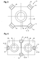
- Formwork assembly 12 shown has a formwork member 20 for a cable feedthrough, with a circumferential flange 22 and four positioning elements, of which only two are shown in the figure.
- the formwork assembly 12 can be positioned on the inner wall 34 of a casing 36 and keeps a conduit passage 38 free when pouring in the liquid concrete.
- the casing 36 is in the embodiment shown here of a magnetizable material, such as a metal, whereby the casing 36 is very resistant, for example, for use in a precast plant.
- the formwork component 20 is placed flat on the casing 36 before the pouring of the liquid concrete with the flange 22 and aligned.
- the positioning elements 10 are placed on the flange 22 so that the magnets 18 and the first contact surfaces 14 with the associated magnet 18 rest on the flange 22.
- the four positioning elements are evenly distributed on the flange 22 in the circumferential direction ( FIG. 3 ). Due to the attractive forces between the magnets 14 and the metallic casing 36, the flange 22 is clamped between the magnets 14 and the positioning elements 10 and the casing 36 and so the formwork member 20 securely fixed on the casing 36.
- the second abutment surface 32 is in the assembled state of the positioning elements 10 on the casing 36 and supports the positioning element 10 so that the first contact surface 18 and the magnet 14 rests flat on the flange 22.
- the length of the projection 30 is selected so that the distance A between the first contact surface 18 and the second contact surface 32 of the thickness D of the flange 22 corresponds.
- the first abutment surface 18 lies flat on the flange 22 and is aligned substantially parallel to the casing, so that a uniform pressure distribution on the flange takes place.
- the second contact surface 32 is thus, for example, with a narrower flange 22 or a non-exact positioning of the positioning element on the flange 22, tilting of the magnet 14 and the first bearing surface 18 from the flange 22 away reliably prevented.
- the positioning elements 10 are gripped on the gripping section 26 and on the second leg 16 and moved in a pivoting direction S such that the positioning element 10 turns away from the formwork component 20 by a pivot point 40 Edge of the second abutment surface 32 is pivoted in the pivoting direction S, wherein the first leg 14 is lifted with the magnet 24 and pivoted away from the flange 22. As soon as the distance between magnet 24 and casing 36 increases, the attraction between magnet 24 and casing 36 decreases, so that after pivoting of the positioning element 10, a problem-free handling of the positioning element 10 is possible.
- the lever arm for the pivoting force which is required to pivot the positioning element, increased and the pivoting force can thus be reduced, so that even with strong magnets 24 a release with low pivoting force is possible. Since the pivot point 40 or the second contact surface 32 rests on the metallic casing 36, a stable counter bearing for pivoting the positioning element 10 is produced, for example, in the case of very strong magnets 24, which require a greater pivoting force.
- the magnet 24 has a sufficiently large distance to the second leg 16, so that when the positioning member 10 rests flat with the second leg 16 on the casing 36, a sufficiently large distance between the magnet 24 and casing 36 is formed, whereby the attraction of the magnet 24 is not sufficient to fix the positioning element 10 on the casing 36. Unintentional adhesion of the positioning element 10 on the casing 36 is thus prevented.
- the positioning element 10 is located with the second contact surface 32 and the tip of the first leg 14, a simple release by tilting in the pivoting direction S about the second contact surface 32 is possible.
- the second contact surface 32 of the positioning element 10 ensures, for example, with narrower flanges 22, that the contact surface 18 or the magnet 14 rests flat on the flange 22.
- the pivot point 40 is in such an embodiment at the contact point of the two legs 14, 16th
- the angle between the legs 14, 16 can also be varied as desired. It is only necessary to ensure that the positioning element 10 can be pivoted sufficiently to establish a sufficient distance between the magnet 14 and the casing 36 and thus to overcome the attraction of the magnets 14.
- the angle ⁇ between the legs 14, 16 is for this reason preferably less than 180 °.
- the position of the second contact surface 32 can also be varied as desired.
- the projection 30 is preferably arranged at an angle to the first leg of approximately 90 °.
- the formwork component 20 is in the embodiment shown here, a line feedthrough, which keeps a line break 34.
- additional elements may be arranged, for example, a fire protection element which closes the line breakthrough 34 smokeless and fire-proof in case of fire.
- the fire protection element can be made of an intumescent material that foams under the action of heat.
- the flange is of rectangular design and has in each case a support 34 for the positioning elements 10 in the corners.
- the number and the position of the positioning elements 10 can also be varied as desired.
- FIG. 4 a second embodiment of a formwork assembly 12 according to the invention is shown.
- two formwork members 20 are provided, wherein for both formwork members 20 a total of four positioning elements 10 are provided. Two of the positioning elements 10 are arranged so that they each fix both formwork members 20.
Landscapes
- Engineering & Computer Science (AREA)
- Architecture (AREA)
- Mechanical Engineering (AREA)
- Civil Engineering (AREA)
- Structural Engineering (AREA)
- Manufacturing & Machinery (AREA)
- Chemical & Material Sciences (AREA)
- Ceramic Engineering (AREA)
- Forms Removed On Construction Sites Or Auxiliary Members Thereof (AREA)
Priority Applications (1)
| Application Number | Priority Date | Filing Date | Title |
|---|---|---|---|
| EP13178155.1A EP2829373A1 (fr) | 2013-07-26 | 2013-07-26 | Elément de positionnement et module de coffrage |
Applications Claiming Priority (1)
| Application Number | Priority Date | Filing Date | Title |
|---|---|---|---|
| EP13178155.1A EP2829373A1 (fr) | 2013-07-26 | 2013-07-26 | Elément de positionnement et module de coffrage |
Publications (1)
| Publication Number | Publication Date |
|---|---|
| EP2829373A1 true EP2829373A1 (fr) | 2015-01-28 |
Family
ID=48877098
Family Applications (1)
| Application Number | Title | Priority Date | Filing Date |
|---|---|---|---|
| EP13178155.1A Withdrawn EP2829373A1 (fr) | 2013-07-26 | 2013-07-26 | Elément de positionnement et module de coffrage |
Country Status (1)
| Country | Link |
|---|---|
| EP (1) | EP2829373A1 (fr) |
Citations (5)
| Publication number | Priority date | Publication date | Assignee | Title |
|---|---|---|---|---|
| DE1988962U (de) * | 1968-03-16 | 1968-07-04 | Deutsche Edelstahlwerke Ag | Magnetisches haftgeraet. |
| DE8333171U1 (de) | 1983-11-18 | 1984-04-19 | Ostermann, Jörn-Hinrich, 2359 Kisdorf | Vorrichtung zur herstellung verschliessbarer installationsdurchbrueche |
| DE4237466A1 (de) | 1992-11-06 | 1994-05-11 | Dyckerhoff & Widmann Ag | Vorrichtung zum Befestigen eines Einbauteils in einer Schalung zum Herstellen von Fertigbauteilen aus Beton |
| WO2001020103A1 (fr) * | 1999-09-15 | 2001-03-22 | Victor Emmanuel Cassar | Dispositif de retenue de bague |
| EP1293714A1 (fr) * | 2001-09-17 | 2003-03-19 | HILTI Aktiengesellschaft | Passage de conduit, encastrable et expansible |
-
2013
- 2013-07-26 EP EP13178155.1A patent/EP2829373A1/fr not_active Withdrawn
Patent Citations (5)
| Publication number | Priority date | Publication date | Assignee | Title |
|---|---|---|---|---|
| DE1988962U (de) * | 1968-03-16 | 1968-07-04 | Deutsche Edelstahlwerke Ag | Magnetisches haftgeraet. |
| DE8333171U1 (de) | 1983-11-18 | 1984-04-19 | Ostermann, Jörn-Hinrich, 2359 Kisdorf | Vorrichtung zur herstellung verschliessbarer installationsdurchbrueche |
| DE4237466A1 (de) | 1992-11-06 | 1994-05-11 | Dyckerhoff & Widmann Ag | Vorrichtung zum Befestigen eines Einbauteils in einer Schalung zum Herstellen von Fertigbauteilen aus Beton |
| WO2001020103A1 (fr) * | 1999-09-15 | 2001-03-22 | Victor Emmanuel Cassar | Dispositif de retenue de bague |
| EP1293714A1 (fr) * | 2001-09-17 | 2003-03-19 | HILTI Aktiengesellschaft | Passage de conduit, encastrable et expansible |
Similar Documents
| Publication | Publication Date | Title |
|---|---|---|
| EP3361215B1 (fr) | Dispositif de retenue pour un appareil laser | |
| EP2330261A1 (fr) | Dispositif d'ajustement de carrelages | |
| DE202016101962U1 (de) | Elektroinstallationsgehäuse zur Aufnahme einer elektrotechnischen Einrichtung in einem Betonteil | |
| EP3534476A1 (fr) | Boîte d'installation | |
| DE102011088456A1 (de) | Positionierungselement und Anordnung zum Positionieren zumindest eines stabförmigen Bewehrungselementes | |
| EP2511580B2 (fr) | Passage destiné à l'intégration dans un élément de paroi ou de sol | |
| DE102018124980B3 (de) | Verfahren und Halbzeug zur Herstellung eines Beton-Doppelwandelements | |
| EP3519641A1 (fr) | Dispositif de liaison servant à relier des éléments préfabriqués à paroi mince et éléments préfabriqués équipés de ce dispositif | |
| EP2829373A1 (fr) | Elément de positionnement et module de coffrage | |
| WO2010089065A1 (fr) | Dispositif de serrage | |
| DE102008010172A1 (de) | Verbindungsmechanismus für einen Fundamenterder | |
| DE2726672C3 (de) | Wanddurchführung für Erdleiter, insbesondere Erdbandeisen | |
| EP2196599A2 (fr) | Corps de butée pour coffrages de béton | |
| EP2947734B1 (fr) | Dispositif d'installation électrique pour la construction en béton | |
| DE3111180A1 (de) | "installations-kleinverteiler fuer unterputzmontage" | |
| EP2363552A1 (fr) | Utilisation d'une rehausse pour le rehaussement sur un bourrage d'étanchéité | |
| DE202011001382U1 (de) | Installationsteil | |
| DE2641682C3 (de) | Mauerdurchführung für Kabel, Rohre o.dgl. | |
| DE102021209089B4 (de) | Verfahren zur Herstellung eines aus Beton gegossenen Wand- oder Decken-Plattenelements | |
| EP4269054B1 (fr) | Elément de double paroi en béton ainsi que produit semi-fini et dispositif de support pour sa fabrication | |
| DE19757450C1 (de) | Steigeisen für Beton-Schachtringe und dgl. Betonfertigteile | |
| DE102014213067A1 (de) | Rohrhalter | |
| WO2018206313A1 (fr) | Élément d'étanchéité et ensemble de protection anti-incendie comprenant un élément d'étanchéité | |
| DE102024106099A1 (de) | Anordnung und Verfahren zum Eingießen in eine Bodenplatte | |
| AT314786B (de) | Abstandshalter für Bewehrung und Schalung bei wandartigen Betonteilen, Betonstützen und Betonbalken sowie bei doppelbewehrten Decken |
Legal Events
| Date | Code | Title | Description |
|---|---|---|---|
| 17P | Request for examination filed |
Effective date: 20130726 |
|
| AK | Designated contracting states |
Kind code of ref document: A1 Designated state(s): AL AT BE BG CH CY CZ DE DK EE ES FI FR GB GR HR HU IE IS IT LI LT LU LV MC MK MT NL NO PL PT RO RS SE SI SK SM TR |
|
| AX | Request for extension of the european patent |
Extension state: BA ME |
|
| PUAI | Public reference made under article 153(3) epc to a published international application that has entered the european phase |
Free format text: ORIGINAL CODE: 0009012 |
|
| STAA | Information on the status of an ep patent application or granted ep patent |
Free format text: STATUS: THE APPLICATION IS DEEMED TO BE WITHDRAWN |
|
| 18D | Application deemed to be withdrawn |
Effective date: 20150729 |