EP2829380B1 - Cintreuse destiner à cintrer des pièces à usiner en thermoplastique - Google Patents
Cintreuse destiner à cintrer des pièces à usiner en thermoplastique Download PDFInfo
- Publication number
- EP2829380B1 EP2829380B1 EP14170189.6A EP14170189A EP2829380B1 EP 2829380 B1 EP2829380 B1 EP 2829380B1 EP 14170189 A EP14170189 A EP 14170189A EP 2829380 B1 EP2829380 B1 EP 2829380B1
- Authority
- EP
- European Patent Office
- Prior art keywords
- bending
- hydraulic
- pressure
- pressure chamber
- drive
- Prior art date
- Legal status (The legal status is an assumption and is not a legal conclusion. Google has not performed a legal analysis and makes no representation as to the accuracy of the status listed.)
- Active
Links
Images

Classifications
-
- B—PERFORMING OPERATIONS; TRANSPORTING
- B29—WORKING OF PLASTICS; WORKING OF SUBSTANCES IN A PLASTIC STATE IN GENERAL
- B29C—SHAPING OR JOINING OF PLASTICS; SHAPING OF MATERIAL IN A PLASTIC STATE, NOT OTHERWISE PROVIDED FOR; AFTER-TREATMENT OF THE SHAPED PRODUCTS, e.g. REPAIRING
- B29C53/00—Shaping by bending, folding, twisting, straightening or flattening; Apparatus therefor
- B29C53/02—Bending or folding
- B29C53/04—Bending or folding of plates or sheets
Definitions
- the invention relates to a bending machine for bending workpieces made of thermoplastic material according to the preamble of claim 1.
- Bending machines for bending plate-shaped workpieces made of thermoplastic material have an elongated machine frame, in which a workpiece to be bent can be inserted horizontally.
- a bending device having a clamping device for clamping the non-bending part of the workpiece and a pivotally mounted, strip-shaped bending cheek, with the bent part of the workpiece are bent by pivoting the bending cheek by means of a pivot drive up can.
- a heating device and a holding device are provided.
- the heater has two superimposed, horizontally extending heating blades, which are each attached to support beams.
- the support beams are each vertically movable by means of actuators, so that the heat exchangers can be brought into contact with the workpiece from both sides.
- the heating blades are heated by means of electrical energy and, when placed against the workpiece, provide a plasticized bending line which allows the bending of a part of the workpiece about the bending line in the bending direction.
- Typical bending machine of the generic type are the DE 195 15 719 U . EP 0 425 724 A1 . DE 92 14 576 U1 . EP 0 426 075 A2 and DE 36 37 436 A1 refer to. For a more detailed explanation of this type of bending machines, reference is made to the content of these documents.
- thermoplastic composite materials For bending in particular of thermoplastic composite materials also generic bending machines are known in which both the bending line adjacent parts of the workpiece are bent at the same time around a bending beam after plasticizing the bending line. In this case act as a pivot drive drive pressure cylinder directly on the outsides of the parts to be bent of the workpiece.
- a bending machine is the EP 0 456 121 A1 refer to.
- part-turn actuators For pivoting the bending cheeks of generic bending machines part-turn actuators are known which have an electric motor with gear (see. EP 0 426 065 A2 . DE 92 14 576 U1 . EP 0 425 724 A1 and DE 36 37 436 A1 ). Such rotary actuators allow for precise adjustment and reproducible compliance with the swivel angle. However, such part-turn actuators are structurally complex and therefore expensive. For this reason, rotary actuators have been provided which have a plurality, over the length of the bending cheek evenly distributed drive pressure cylinder (see. DE 295 15 719 U1 ).
- Such drive pressure cylinders each have a retractable and retractable piston rod and a piston attached thereto, which divides the interior of the drive pressure cylinder into a first and a second pressure chamber.
- the piston rod When pressure is applied to the first pressure chamber, the piston rod is moved in a direction that effects a bending operation. As a rule, it is extended out of the cylinder.
- a return device is provided, which moves the piston rod back to a starting position after the bending operation.
- the drive pressure cylinder - as well as for the pressure cylinder for moving the heating blades - compressed air is used without exception, since in companies where such bending machines are used, usually compressed air is available via a compressed air source.
- the bending machine itself may be provided with a suitable compressor for generating compressed air.
- the invention has for its object to make the pivot drive for a bending machine of the generic type such that with comparable simple means a reproducible bending result can be achieved.
- the basic idea of the invention is to still effect the bending operation by connection to a pneumatic pressure source, but to hydraulically throttle the movement of the piston rod of the drive pressure cylinder or drive pressure cylinder and to lock it hydraulically when the desired bending angle is reached.
- This is achieved by means of a hydraulic part, which develops a throttling action and is provided with at least one check valve.
- the throttling effect of the hydraulic part results in a uniform pivoting movement, which is largely independent of the pressure of the pneumatic pressure source and the weight and bending resistance of the workpiece to be bent.
- the check valve or the check valves With the help of the check valve or the check valves, a certain bending angle can be reproducibly achieved because the hydraulic fluid present in the hydraulic pressure part is incompressible.
- the respective bending angle can be detected by means of electronic sensors and used to control the or the check valves. Even if the hydropneumatics according to the invention is more complex than a purely pneumatic rotary actuator, the cost is significantly lower than in electromotive rotary actuators.
- the return device can consist of a spring, which becomes effective when the pressure in the first pressure chamber is relieved.
- the hydraulic part has as restoring device at least one pressure medium converter with a hydraulic pressure chamber connected to the hydraulic part and separated by a piston a pneumatic pressure chamber which is connectable to the pneumatic pressure source for the purpose of resetting the drive pressure cylinder or the drive pressure cylinder.
- the pneumatic pressure chamber should be connectable to the atmosphere during the bending process, so that during the bending process in him no movement of the piston rods opposing acting pressure builds up.
- the hydraulic part has at least one throttle valve, via which the throttle effect is adjustable.
- the throttle valve may also be designed as a throttle check valve, which is installed such that its check valve locks during the bending process, but vice versa opens during the reset operation.
- the hydraulic part is expedient for the hydraulic part to be composed of a respective hydraulic part section assigned to a drive pressure cylinder, wherein each hydraulic section is connected in common to a single pressure medium converter.
- each hydraulic section is connected in common to a single pressure medium converter.
- bending machine 1 has a cuboid machine frame 2, whose end face in FIG. 1 you can see. It is elongated perpendicular to the plane of the drawing, so that the longitudinal direction of the machine frame 2 extends in this direction.
- a lower cross member 3 and an upper cross member 4 which is supported by a front vertical beam 5 and a rear vertical beam 6.
- the lower cross member 3 is connected via a front lower longitudinal spar 7 with the front vertical spar 5 and a rear lower longitudinal spar 8 with the rear vertical spar 6.
- Both lower longitudinal beams 7, 8 extend perpendicular to the plane of the drawing over the entire length of the bending machine 1.
- In the upper area also longitudinal spars are present, of which only the rear upper longitudinal spar 9 can be seen here. All four longitudinal beams 7, 8 extend horizontally to the other end face of the bending machine 1, where they are connected to the local vertical beams and cross beams, which are present on this end face in the same arrangement as on the end face shown here.
- a carriage 10 is displaceably guided in the directions of the double arrow A.
- the carriage 10 has a U-shaped frame 11 with an upper horizontal leg 12 and thus connected by a vertical spar 13 lower horizontal leg 14.
- a corresponding frame is provided congruent to the other end face.
- Both frames 11 are connected via a horizontally and parallel to the rear upper longitudinal spar 9 extending clamping member 15, so that the two frames 11 form a unit with the clamping member 15.
- clamping member 15 extends in the same length and parallel to him a cross-sectionally triangular terminal block 16. It is not shown here via pneumatic pressure cylinder and vertical guides relative to the clamping member 15 liftable and lowered in the direction of him.
- the terminal block 16 is part of the carriage 10, so it always remains above the clamping member 15 during movement of the carriage 10.
- a vertically upwardly extending guide rod 17 is attached at the lower horizontal leg 14 of the frame 11.
- a corresponding guide rod also has the frame present on the other end face.
- an upper heater blade 18 and a lower heater blade 19 are guided vertically displaceable. They extend parallel to the clamping member 15 and the terminal block 16 over the entire length of the bending machine from the frame 11 to the other frame.
- the heater blades 18, 19 are moved vertically, ie from the drawn starting positions, the upper heat shield 18 can be moved down and the lower heating blade 19 upwards.
- the heating blades 18, 19 are heated with electrical energy to a temperature with which it is possible, workpieces made of thermoplastic material from both sides linear to plasticize. Due to the attachment to the lower horizontal legs 14, the guide rods 17 and thus the two heating blades 18, 19 are movable with the carriage 10 in the directions of the double arrow A.
- the top of the front upper longitudinal beam is at the same height as the top of the clamping beam 15 on the carriage 10.
- the terminal block 20 is vertically movable by means not shown here pneumatic pressure cylinder.
- the clamping strip 20 extends perpendicular to the plane of the drawing and parallel to the opposite longitudinal spar approximately over the entire length of the bending machine 1. In the open position, a plastic plate between the terminal block 20 and the top of the opposite longitudinal spar can be clamped.
- a bending cheek 23 is mounted on a horizontally extending pivot joint 22. It extends essentially across the width of the machine frame 2. In the starting position shown, its surface is horizontal and flush with the top of the front upper longitudinal spar. It can be pivoted from this position to a vertical position.
- a pivot drive 24 is provided for the pivoting of the bending beam 23.
- this pivot drive 24 includes three drive pressure cylinder, which are evenly distributed over the length (perpendicular to the plane of the drawing) of the bending cheek 23 and of which only the first in this view first drive pressure cylinder 25 can be seen.
- Each drive pressure cylinder 25 has a cylinder housing 26 from which a piston rod 27 projects upwards.
- the cylinder housing 26 sit at the bottom each articulated on a support bracket 28 which is fixed to the machine frame 2.
- the piston rods 27 are connected via joints 29 with the underside of the bending cheek 23. By extending the piston rods 27, the bending cheek 23 can be pivoted from the initial position shown by a desired bending angle.
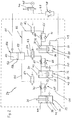
- the hydraulic circuit diagram according to FIG. 2 shows the three drive pressure cylinders 25, 30, 31 in a schematic representation with their cylinder housings 26, 32, 33 and the upwardly projecting respectively piston rods 27, 34, 35.
- the bottom-side support of the cylinder housing 26, 32, 33 on the support brackets 28 is also omitted as the articulated connection of the free ends of the piston rods 27, 34, 35 on the bending cheek 23.
- the projecting into the cylinder housing 26, 32, 33 ends of the piston rods 27, 34, 35 are provided with pistons 36, 37, 38, which are the interiors the cylinder housing 26, 32, 33 each in a first pressure chamber 39, 40, 41 and in a piston rod side second pressure chamber 42, 43, 44 split.
- the pressure medium supply of the drive pressure cylinders 25, 30, 31 takes place primarily by a compressed air source 45 which can be designed externally as a compressed air system of an operation to which the bending machine 1 is connected or as a compressor belonging to the bending machine 1 with compressed air reservoir.
- a control valve 46 In the flow direction behind the compressed air source 45 is a control valve 46 which can be switched electromagnetically by a control panel.
- a central compressed air line 47 connects, in which a throttle-check valve 48 is arranged.
- the central compressed air line 47 is then divided into three compressed air line sections 49, 50, 51 which are each connected to the associated first pressure chamber 39, 40, 41 of the drive pressure cylinders 25, 30, 31.
- the second pressure chambers 42, 43, 44 are connected to a hydraulic part designated as a whole by 52.
- the hydraulic part 52 has for each drive pressure cylinder 25, 30, 31, a hydraulic line section 53, 54, 55, which are each open to the associated second pressure chamber 42, 43, 44 and how they are filled with hydraulic oil.
- the hydraulic line sections 53, 54, 55 open into a pressure medium converter 56, which has a cylinder housing 57, in which a separating piston 58 is arranged to be vertically displaceable.
- the separating piston 58 divides the cylinder housing 57 into a hydraulic pressure chamber 59 filled with hydraulic oil and a pneumatic pressure chamber 60 arranged above it. This is connected via a pneumatic line 61 to the control valve 46.
- a check valve 62, 63, 64 is arranged, with which the flow can be opened or locked.
- a throttle check valve 65, 66, 67 is arranged in each case, which has a throttle 68, 69, 70 in the main path and a check valve 71, 72, 73 in the bypass ,
- a bending operation is initiated by connecting the compressed air source 45 to the central compressed air line 47 via the control valve 46, as shown in FIG FIG. 2 is shown.
- the compressed air then flows via the compressed air line sections 49, 50, 51 into the first pressure chambers 39, 40, 41, with the result that the pistons 36, 37, 38 and thus the piston rods 27, 34, 35 are raised, ie the first pressure chambers 39, 40, 41 enlarge and reduce the second pressure chambers 42, 43, 44.
- the hydraulic oil in the second pressure chambers 42, 43, 44 in the hydraulic line sections 53, 54, 55 displaced and flows through the blockage by the check valves 71, 72, 73, the throttles 68, 69, 70.
- the bending process has just been completed, because the check valves 62, 63, 64 are switched to blocking position.
- the control of the check valves 62, 63, 64 can be done automatically by a certain bending angle of the bending beam 23 is entered.
- the check valves 62, 63, 63 are then closed when the set bending angle is reached. Due to the incompressibility of the hydraulic oil, the desired bending angle is obtained in any desired reproducible manner.
- the continued air pressure of the first pressure chambers 39, 40, 41 provides for a more stable end position of the pistons 36, 37, 38 and thus ultimately the bending cheek 23rd
- the control valve 46 is switched so that on the one hand the pneumatic line 61 is connected to the compressed air source 45 and on the other hand, the central compressed air line 47 vented, that is opened to the atmosphere.
- the check valves 62, 63, 64 are switched back to the open position.
- the compressed air flowing into the pneumatic pressure chamber 60 shifts the separating piston 58 downwards and displaces it in the hydraulic pressure chamber Hydraulic oil flows through the check valves 62, 63, 64 and via the bypasses now open check valves 71, 72, 73 and enters the second pressure chambers 42, 43, 44.
- the hydraulic oil flows through the hydraulic fluid Pistons 36, 37, 38 moves downward, wherein the air in the first pressure chambers 39, 40, 41 is displaced and throttled flows through the throttle check valve 48 to the outside.
- the reset is terminated by switching the check valves 62, 63, 64 in the locked position.
- a bending operation with the bending machine 1 according to FIG. 1 is designed as follows.
- the carriage 10 is brought from a control panel forth in the shown front end position to define a zero position for the control device.
- the terminal strips 16, 20 are in a raised starting position.
- the bending cheek 23 is opposite to in FIG. 1 shown rotated position 90 ° upwards to form a stop. It can then be inserted from the right first between the terminal block 16 and the clamping member 15 and then further forward between the terminal block 20 and the front lower upper longitudinal beam located thereunder, until it comes to rest with its front edge on the bending cheek 23.
- the distance is now entered, in which the bending line to come to rest on the bending cheek 23 free edge of the plastic plate to come to rest.
- the further procedure is then controlled either automatically by hand, ie semi-automatically, or by appropriate programming of the control device.
- the plastic plate is fixed in position by the clamping bar 20 is lowered with bias on the plastic plate and pressed against the underlying longitudinal beam. Subsequently, the carriage 10 is moved with raised terminal block 16 by appropriate control of a not shown here positioning drive to the rear, ie from the terminal block 20 away, by such an amount that the heat saber 18, 19 after stopping the carriage 10 above the provided bend line to come.
- the plastic plate is then clamped by lowering the terminal block 16 in the direction of the clamping member 15.
- the two heat shields 12, 13 are approached to each other until they have come to rest on the top or the bottom of the plastic plate. They then heat the plastic in the area of the intended bending line so strongly that it becomes plastically plasticized and flexible.
- the clamping bar 20 of the clamping device 21 When the bending line is sufficiently heated, the clamping bar 20 of the clamping device 21 is raised. After swinging back the bending beam 23 in the initial position shown, the carriage 10 is moved by appropriate control of the positioning again in the direction of the bending beam 23, wherein the plastic plate is taken because of the fixation between the terminal block 16 and the clamping member 15. At the same time, the heating swords 12, 13 are released from the plastic plate and moved so far up or down that they can not collide with the further ancestor of the carriage 10 with the clamping device 21.
- the horizontal distance between the Edelhetern 12, 13 and the terminal block 16 and the clamping member 15 is dimensioned so that the heated bending line comes to rest on reaching the front end position of the carriage 10 about above the pivot joint 22.
- the clamping device 21 is closed by lowering the terminal block 20 and thus clamped the plastic plate.
- the drive pressure cylinders 25, 30, 31 are driven in order to initiate the bending operation in the manner described above, so that the bending cheek 23 from the in FIG. 1 shown starting position is swung up.
- the deferred on the bending beam 23 part of the plastic plate is bent up accordingly, with any desired bending angle can be adjusted by suitable input to the control device.
- the jamming of the plastic plate between the clamping member 15 and terminal block 16 is released again and the carriage 10 by means of the positioning cylinder moved to the rear until the Schuter 12, 13 again with the next aligned bend line.
- the distance to the first bendline may be determined by appropriate input to the controller, i. this distance can be the same as in the first bending process, but it can also be given a different distance.
- the plastic plate is clamped by lowering the terminal block 16 and the Schuter 12, 13 brought from above or from below to the surfaces of the plastic plate to the plant.
Landscapes
- Engineering & Computer Science (AREA)
- Mechanical Engineering (AREA)
- Shaping Of Tube Ends By Bending Or Straightening (AREA)
- Bending Of Plates, Rods, And Pipes (AREA)
Claims (7)
- Machine de cintrage destinée à cintrer des pièces à usiner en matière thermoplastique, comprenant un dispositif de cintrage qui présente un dispositif de chauffage (18, 19) pour la plastification d'une ligne de cintrage sur la pièce à usiner et un entraînement pivotant (24) pouvant être relié à une source de pression pneumatique (45), destiné à faire pivoter une partie de la pièce à usiner autour de la ligne de cintrage, lequel présente au moins un cylindre de pression d'entraînement (25, 30, 31) muni d'une tige de piston (27, 34, 35) pouvant rentrer et sortir et d'un piston (36, 37, 38) qui y est fixé, lequel divise l'intérieur du cylindre de pression d'entraînement (25, 30, 31) en une première chambre de pression (39, 40, 41), lors de la mise sous pression de laquelle la tige de piston (27, 34, 35) est déplacée dans une direction pouvant causer une opération de cintrage, et en une deuxième chambre de pression (42, 43, 44), la mise sous pression de la première chambre de pression (39, 40, 41) pouvant être réalisée par pression pneumatique, et un dispositif de rappel pour le mouvement de la tige de piston (27, 34, 35) en direction inverse étant associé au cylindre de pression d'entraînement (25, 30, 31), caractérisée en ce que le cylindre de pression d'entraînement, respectivement les cylindres de pression d'entraînement (25, 30, 31), est réalisé, respectivement en tant que cylindre de pression d'entraînement (25, 30, 31) hydropneumatique, avec la première chambre de pression (39, 40, 41) étant prévue comme chambre de pression pneumatique et avec la deuxième chambre de pression (42, 43, 44) étant prévue comme chambre de pression hydraulique, et en ce que respectivement la chambre de pression pneumatique peut être reliée à la source de pression pneumatique (45) et en ce qu'une partie hydraulique (52) se raccorde à la chambre de pression hydraulique, respectivement aux chambres de pression hydraulique, laquelle lors de l'opération de cintrage, en raison de la mise sous pression de la chambre de pression pneumatique, respectivement des chambres de pression pneumatique, agit comme étrangleur hydraulique (65, 66, 67), la partie hydraulique (52) présentant au moins une vanne d'arrêt (62, 63, 64) commutable, à l'aide de laquelle l'écoulement de fluide hydraulique hors de la chambre de pression hydraulique, respectivement des chambres de pression hydraulique, peut être arrêté.
- Machine de cintrage selon la revendication 1, caractérisée en ce que la partie hydraulique (52) présente en tant que dispositif de rappel au moins un convertisseur de moyen de pression (56) muni d'une chambre de pression hydraulique (59) reliée à la partie hydraulique (52) et d'une chambre de pression pneumatique (60) séparée par un piston (58), ou laquelle chambre de pression pneumatique peut être raccordée à la source de pression pneumatique (45) pour le rappel du cylindre de pression d'entraînement, respectivement des cylindres de pression d'entraînement (25, 30, 31).
- Machine de cintrage selon la revendication 1 ou 2, caractérisée en ce que la partie hydraulique (52) présente au moins une soupape d'étranglement (65, 66, 67) par l'intermédiaire de laquelle l'effet d'étranglement est réglable.
- Machine de cintrage selon la revendication 3, caractérisée en ce que la soupape d'étranglement est réalisée comme clapet anti-retour d'étranglement (65, 66, 67) qui est installée de manière à bloquer son clapet anti-retour (71, 72, 73) lors de l'opération de cintrage.
- Machine de cintrage selon la revendication 3 ou 4, caractérisée en ce que la soupape d'étranglement (65, 66, 67) est disposée entre la chambre de pression hydraulique et la vanne d'arrêt (62, 63, 64).
- Machine de cintrage selon l'une quelconque des revendications 1 à 5, caractérisée en ce que plusieurs cylindres de pression d'entraînement (25, 30, 31) sont présents et en ce que la partie hydraulique (52) est assemblée à partir d'une section de partie hydraulique (53, 54, 55) associée à respectivement un cylindre de pression d'entraînement (25, 30, 31), lesquelles sont raccordées en commun à un convertisseur de pression (52).
- Machine de cintrage selon la revendication 6, caractérisée en ce que chaque section de partie hydraulique (53, 54, 55) présente une vanne d'arrêt, le cas échéant également une soupape d'étranglement (65, 66, 67).
Applications Claiming Priority (1)
| Application Number | Priority Date | Filing Date | Title |
|---|---|---|---|
| DE202013103273.5U DE202013103273U1 (de) | 2013-07-22 | 2013-07-22 | Biegemaschine zum Biegen von Werkstücken aus thermoplastischem Kunststoff |
Publications (2)
| Publication Number | Publication Date |
|---|---|
| EP2829380A1 EP2829380A1 (fr) | 2015-01-28 |
| EP2829380B1 true EP2829380B1 (fr) | 2017-12-20 |
Family
ID=50846817
Family Applications (1)
| Application Number | Title | Priority Date | Filing Date |
|---|---|---|---|
| EP14170189.6A Active EP2829380B1 (fr) | 2013-07-22 | 2014-05-28 | Cintreuse destiner à cintrer des pièces à usiner en thermoplastique |
Country Status (2)
| Country | Link |
|---|---|
| EP (1) | EP2829380B1 (fr) |
| DE (1) | DE202013103273U1 (fr) |
Families Citing this family (1)
| Publication number | Priority date | Publication date | Assignee | Title |
|---|---|---|---|---|
| CA2924687C (fr) | 2015-04-23 | 2019-06-18 | CMP Automation Inc. | Methode de pliage de tube de plastique et appareil |
Family Cites Families (11)
| Publication number | Priority date | Publication date | Assignee | Title |
|---|---|---|---|---|
| US4439986A (en) * | 1981-01-23 | 1984-04-03 | Snitgen Joseph D | Hydraulic power unit |
| JPS58214682A (ja) * | 1982-06-09 | 1983-12-13 | Sumitomo Heavy Ind Ltd | プレス用空気駆動式液圧ポンプ |
| DD227349A1 (de) * | 1984-10-08 | 1985-09-18 | Warnke Umformtech Veb K | Regelanordnung fuer steuerbare pneumatikkissen |
| DE3637436A1 (de) | 1986-11-04 | 1988-05-11 | Wegener Gmbh & Co Kg | Biegemaschine zur verarbeitung von werkstuecken aus thermoplastischem kunststoff |
| JPH0616957B2 (ja) * | 1989-10-05 | 1994-03-09 | フガク工機株式会社 | 圧縮成形機におけるラムの昇降機構 |
| AU636921B2 (en) | 1989-10-30 | 1993-05-13 | Syntex (U.S.A.) Inc. | Benzylpyrrolidine derivatives as dopamine agonists |
| ES2045342T3 (es) | 1989-11-01 | 1994-01-16 | Wegener Gmbh | Maquina dobladora para piezas de plastico. |
| ES2062257T3 (es) | 1989-11-01 | 1994-12-16 | Wegener Gmbh | Maquina para curvar para el doblado multiple y sucesivo de piezas de trabajo. |
| ATE120125T1 (de) | 1990-05-10 | 1995-04-15 | Wegener Gmbh | Verfahren zum biegen von plattenförmigen werkstücken sowie biegemaschine zur durchführung des verfahrens. |
| DE9214576U1 (de) | 1992-10-28 | 1992-12-17 | Wegener GmbH, 5100 Aachen | Maschine zum thermischen Verarbeiten von Werkstücken aus thermoplastischem Kunststoff |
| DE29515719U1 (de) | 1995-10-04 | 1995-12-14 | Wegener Gmbh, 52074 Aachen | Biegemaschine |
-
2013
- 2013-07-22 DE DE202013103273.5U patent/DE202013103273U1/de not_active Expired - Lifetime
-
2014
- 2014-05-28 EP EP14170189.6A patent/EP2829380B1/fr active Active
Non-Patent Citations (1)
| Title |
|---|
| None * |
Also Published As
| Publication number | Publication date |
|---|---|
| DE202013103273U1 (de) | 2014-10-23 |
| EP2829380A1 (fr) | 2015-01-28 |
Similar Documents
| Publication | Publication Date | Title |
|---|---|---|
| DE3243214A1 (de) | Einrichtung zum automatischen einziehen eines dichtungsstreifens in eine nut eines rahmens | |
| EP1813150A2 (fr) | Rampe de pulvérisation pour pulvérisateur agricole | |
| EP1900476B1 (fr) | Machine-outil dotée d'un espace de travail | |
| DE10306524B4 (de) | Vorrichtung und Verfahren zum Schweißen von Kunststoffprofilen | |
| DE2128717C3 (de) | Verfahren zum Aufbringen eines metallischen Abstandhalters auf die Scheibenränder einer der rechteckigen Glasplatten einer Isolierverglasung und Vorrichtung zur Durchführung des Verfahrens | |
| EP1990130A1 (fr) | Machine de traitement de bords | |
| DE202004012593U1 (de) | Vorrichtung zur Festlegung und/oder Positionierung von Gegenständen in einem Transportbehälter | |
| EP2829380B1 (fr) | Cintreuse destiner à cintrer des pièces à usiner en thermoplastique | |
| EP1123831B1 (fr) | Appui-tête pour sièges de véhicule | |
| DE3637436C2 (fr) | ||
| DE3246893A1 (de) | Pneumatisch oder hydraulisch betaetigbare rahmenpresse | |
| DE2110540A1 (de) | Rahmen-Schweissmaschine | |
| DE3817005C2 (de) | Schweißmaschine zur Herstellung von Rahmen | |
| DE102013200851A1 (de) | Biegevorrichtung für strangförmige Werkstücke | |
| DE202008016254U1 (de) | Variable Absaugung | |
| DE202016007378U1 (de) | Verstellvorrichtung für eine Bedieneinheit einer Werkzeugmaschine sowie Werkzeugmaschine mit Verstellvorrichtung | |
| EP0426065A2 (fr) | Machine à plier | |
| EP3302842B1 (fr) | Procédé de réglage d'une section de formage d'un outil de cintrage | |
| DE4024634C2 (fr) | ||
| DE2300626A1 (de) | Schweissvorrichtung fuer profile | |
| DE10023073B4 (de) | Schutzelement-Antrieb-System | |
| DE2457630C3 (de) | Bewegliche Sicherheitsabschirmung für kraftbetriebene Pressen | |
| DE9214576U1 (de) | Maschine zum thermischen Verarbeiten von Werkstücken aus thermoplastischem Kunststoff | |
| DE29515719U1 (de) | Biegemaschine | |
| DE7108276U (de) | Rahmen Schweißmaschine |
Legal Events
| Date | Code | Title | Description |
|---|---|---|---|
| 17P | Request for examination filed |
Effective date: 20140528 |
|
| AK | Designated contracting states |
Kind code of ref document: A1 Designated state(s): AL AT BE BG CH CY CZ DE DK EE ES FI FR GB GR HR HU IE IS IT LI LT LU LV MC MK MT NL NO PL PT RO RS SE SI SK SM TR |
|
| AX | Request for extension of the european patent |
Extension state: BA ME |
|
| PUAI | Public reference made under article 153(3) epc to a published international application that has entered the european phase |
Free format text: ORIGINAL CODE: 0009012 |
|
| R17P | Request for examination filed (corrected) |
Effective date: 20150305 |
|
| RBV | Designated contracting states (corrected) |
Designated state(s): AL AT BE BG CH CY CZ DE DK EE ES FI FR GB GR HR HU IE IS IT LI LT LU LV MC MK MT NL NO PL PT RO RS SE SI SK SM TR |
|
| GRAP | Despatch of communication of intention to grant a patent |
Free format text: ORIGINAL CODE: EPIDOSNIGR1 |
|
| INTG | Intention to grant announced |
Effective date: 20170824 |
|
| GRAS | Grant fee paid |
Free format text: ORIGINAL CODE: EPIDOSNIGR3 |
|
| GRAA | (expected) grant |
Free format text: ORIGINAL CODE: 0009210 |
|
| AK | Designated contracting states |
Kind code of ref document: B1 Designated state(s): AL AT BE BG CH CY CZ DE DK EE ES FI FR GB GR HR HU IE IS IT LI LT LU LV MC MK MT NL NO PL PT RO RS SE SI SK SM TR |
|
| REG | Reference to a national code |
Ref country code: GB Ref legal event code: FG4D Free format text: NOT ENGLISH |
|
| REG | Reference to a national code |
Ref country code: CH Ref legal event code: EP |
|
| REG | Reference to a national code |
Ref country code: IE Ref legal event code: FG4D Free format text: LANGUAGE OF EP DOCUMENT: GERMAN |
|
| REG | Reference to a national code |
Ref country code: AT Ref legal event code: REF Ref document number: 955970 Country of ref document: AT Kind code of ref document: T Effective date: 20180115 |
|
| REG | Reference to a national code |
Ref country code: DE Ref legal event code: R096 Ref document number: 502014006631 Country of ref document: DE |
|
| REG | Reference to a national code |
Ref country code: NL Ref legal event code: MP Effective date: 20171220 |
|
| PG25 | Lapsed in a contracting state [announced via postgrant information from national office to epo] |
Ref country code: FI Free format text: LAPSE BECAUSE OF FAILURE TO SUBMIT A TRANSLATION OF THE DESCRIPTION OR TO PAY THE FEE WITHIN THE PRESCRIBED TIME-LIMIT Effective date: 20171220 Ref country code: LT Free format text: LAPSE BECAUSE OF FAILURE TO SUBMIT A TRANSLATION OF THE DESCRIPTION OR TO PAY THE FEE WITHIN THE PRESCRIBED TIME-LIMIT Effective date: 20171220 Ref country code: NO Free format text: LAPSE BECAUSE OF FAILURE TO SUBMIT A TRANSLATION OF THE DESCRIPTION OR TO PAY THE FEE WITHIN THE PRESCRIBED TIME-LIMIT Effective date: 20180320 Ref country code: SE Free format text: LAPSE BECAUSE OF FAILURE TO SUBMIT A TRANSLATION OF THE DESCRIPTION OR TO PAY THE FEE WITHIN THE PRESCRIBED TIME-LIMIT Effective date: 20171220 |
|
| REG | Reference to a national code |
Ref country code: LT Ref legal event code: MG4D |
|
| PG25 | Lapsed in a contracting state [announced via postgrant information from national office to epo] |
Ref country code: GR Free format text: LAPSE BECAUSE OF FAILURE TO SUBMIT A TRANSLATION OF THE DESCRIPTION OR TO PAY THE FEE WITHIN THE PRESCRIBED TIME-LIMIT Effective date: 20180321 Ref country code: BG Free format text: LAPSE BECAUSE OF FAILURE TO SUBMIT A TRANSLATION OF THE DESCRIPTION OR TO PAY THE FEE WITHIN THE PRESCRIBED TIME-LIMIT Effective date: 20180320 Ref country code: LV Free format text: LAPSE BECAUSE OF FAILURE TO SUBMIT A TRANSLATION OF THE DESCRIPTION OR TO PAY THE FEE WITHIN THE PRESCRIBED TIME-LIMIT Effective date: 20171220 Ref country code: RS Free format text: LAPSE BECAUSE OF FAILURE TO SUBMIT A TRANSLATION OF THE DESCRIPTION OR TO PAY THE FEE WITHIN THE PRESCRIBED TIME-LIMIT Effective date: 20171220 Ref country code: HR Free format text: LAPSE BECAUSE OF FAILURE TO SUBMIT A TRANSLATION OF THE DESCRIPTION OR TO PAY THE FEE WITHIN THE PRESCRIBED TIME-LIMIT Effective date: 20171220 |
|
| PG25 | Lapsed in a contracting state [announced via postgrant information from national office to epo] |
Ref country code: NL Free format text: LAPSE BECAUSE OF FAILURE TO SUBMIT A TRANSLATION OF THE DESCRIPTION OR TO PAY THE FEE WITHIN THE PRESCRIBED TIME-LIMIT Effective date: 20171220 |
|
| PG25 | Lapsed in a contracting state [announced via postgrant information from national office to epo] |
Ref country code: ES Free format text: LAPSE BECAUSE OF FAILURE TO SUBMIT A TRANSLATION OF THE DESCRIPTION OR TO PAY THE FEE WITHIN THE PRESCRIBED TIME-LIMIT Effective date: 20171220 Ref country code: SK Free format text: LAPSE BECAUSE OF FAILURE TO SUBMIT A TRANSLATION OF THE DESCRIPTION OR TO PAY THE FEE WITHIN THE PRESCRIBED TIME-LIMIT Effective date: 20171220 Ref country code: CY Free format text: LAPSE BECAUSE OF FAILURE TO SUBMIT A TRANSLATION OF THE DESCRIPTION OR TO PAY THE FEE WITHIN THE PRESCRIBED TIME-LIMIT Effective date: 20171220 Ref country code: EE Free format text: LAPSE BECAUSE OF FAILURE TO SUBMIT A TRANSLATION OF THE DESCRIPTION OR TO PAY THE FEE WITHIN THE PRESCRIBED TIME-LIMIT Effective date: 20171220 |
|
| PG25 | Lapsed in a contracting state [announced via postgrant information from national office to epo] |
Ref country code: RO Free format text: LAPSE BECAUSE OF FAILURE TO SUBMIT A TRANSLATION OF THE DESCRIPTION OR TO PAY THE FEE WITHIN THE PRESCRIBED TIME-LIMIT Effective date: 20171220 Ref country code: PL Free format text: LAPSE BECAUSE OF FAILURE TO SUBMIT A TRANSLATION OF THE DESCRIPTION OR TO PAY THE FEE WITHIN THE PRESCRIBED TIME-LIMIT Effective date: 20171220 Ref country code: IS Free format text: LAPSE BECAUSE OF FAILURE TO SUBMIT A TRANSLATION OF THE DESCRIPTION OR TO PAY THE FEE WITHIN THE PRESCRIBED TIME-LIMIT Effective date: 20180420 Ref country code: SM Free format text: LAPSE BECAUSE OF FAILURE TO SUBMIT A TRANSLATION OF THE DESCRIPTION OR TO PAY THE FEE WITHIN THE PRESCRIBED TIME-LIMIT Effective date: 20171220 |
|
| REG | Reference to a national code |
Ref country code: DE Ref legal event code: R097 Ref document number: 502014006631 Country of ref document: DE |
|
| PG25 | Lapsed in a contracting state [announced via postgrant information from national office to epo] |
Ref country code: MT Free format text: LAPSE BECAUSE OF FAILURE TO SUBMIT A TRANSLATION OF THE DESCRIPTION OR TO PAY THE FEE WITHIN THE PRESCRIBED TIME-LIMIT Effective date: 20171220 |
|
| PLBE | No opposition filed within time limit |
Free format text: ORIGINAL CODE: 0009261 |
|
| STAA | Information on the status of an ep patent application or granted ep patent |
Free format text: STATUS: NO OPPOSITION FILED WITHIN TIME LIMIT |
|
| 26N | No opposition filed |
Effective date: 20180921 |
|
| PG25 | Lapsed in a contracting state [announced via postgrant information from national office to epo] |
Ref country code: DK Free format text: LAPSE BECAUSE OF FAILURE TO SUBMIT A TRANSLATION OF THE DESCRIPTION OR TO PAY THE FEE WITHIN THE PRESCRIBED TIME-LIMIT Effective date: 20171220 |
|
| REG | Reference to a national code |
Ref country code: DE Ref legal event code: R119 Ref document number: 502014006631 Country of ref document: DE |
|
| REG | Reference to a national code |
Ref country code: CH Ref legal event code: PL |
|
| GBPC | Gb: european patent ceased through non-payment of renewal fee |
Effective date: 20180528 |
|
| REG | Reference to a national code |
Ref country code: BE Ref legal event code: MM Effective date: 20180531 |
|
| PG25 | Lapsed in a contracting state [announced via postgrant information from national office to epo] |
Ref country code: MC Free format text: LAPSE BECAUSE OF FAILURE TO SUBMIT A TRANSLATION OF THE DESCRIPTION OR TO PAY THE FEE WITHIN THE PRESCRIBED TIME-LIMIT Effective date: 20171220 |
|
| REG | Reference to a national code |
Ref country code: IE Ref legal event code: MM4A |
|
| PG25 | Lapsed in a contracting state [announced via postgrant information from national office to epo] |
Ref country code: LI Free format text: LAPSE BECAUSE OF NON-PAYMENT OF DUE FEES Effective date: 20180531 Ref country code: CH Free format text: LAPSE BECAUSE OF NON-PAYMENT OF DUE FEES Effective date: 20180531 Ref country code: SI Free format text: LAPSE BECAUSE OF FAILURE TO SUBMIT A TRANSLATION OF THE DESCRIPTION OR TO PAY THE FEE WITHIN THE PRESCRIBED TIME-LIMIT Effective date: 20171220 |
|
| PG25 | Lapsed in a contracting state [announced via postgrant information from national office to epo] |
Ref country code: LU Free format text: LAPSE BECAUSE OF NON-PAYMENT OF DUE FEES Effective date: 20180528 |
|
| PG25 | Lapsed in a contracting state [announced via postgrant information from national office to epo] |
Ref country code: IE Free format text: LAPSE BECAUSE OF NON-PAYMENT OF DUE FEES Effective date: 20180528 Ref country code: DE Free format text: LAPSE BECAUSE OF NON-PAYMENT OF DUE FEES Effective date: 20181201 Ref country code: FR Free format text: LAPSE BECAUSE OF NON-PAYMENT OF DUE FEES Effective date: 20180531 Ref country code: GB Free format text: LAPSE BECAUSE OF NON-PAYMENT OF DUE FEES Effective date: 20180528 |
|
| PG25 | Lapsed in a contracting state [announced via postgrant information from national office to epo] |
Ref country code: BE Free format text: LAPSE BECAUSE OF NON-PAYMENT OF DUE FEES Effective date: 20180531 |
|
| PG25 | Lapsed in a contracting state [announced via postgrant information from national office to epo] |
Ref country code: TR Free format text: LAPSE BECAUSE OF FAILURE TO SUBMIT A TRANSLATION OF THE DESCRIPTION OR TO PAY THE FEE WITHIN THE PRESCRIBED TIME-LIMIT Effective date: 20171220 |
|
| PG25 | Lapsed in a contracting state [announced via postgrant information from national office to epo] |
Ref country code: PT Free format text: LAPSE BECAUSE OF FAILURE TO SUBMIT A TRANSLATION OF THE DESCRIPTION OR TO PAY THE FEE WITHIN THE PRESCRIBED TIME-LIMIT Effective date: 20171220 Ref country code: HU Free format text: LAPSE BECAUSE OF FAILURE TO SUBMIT A TRANSLATION OF THE DESCRIPTION OR TO PAY THE FEE WITHIN THE PRESCRIBED TIME-LIMIT; INVALID AB INITIO Effective date: 20140528 |
|
| PG25 | Lapsed in a contracting state [announced via postgrant information from national office to epo] |
Ref country code: MK Free format text: LAPSE BECAUSE OF NON-PAYMENT OF DUE FEES Effective date: 20171220 |
|
| PG25 | Lapsed in a contracting state [announced via postgrant information from national office to epo] |
Ref country code: AL Free format text: LAPSE BECAUSE OF FAILURE TO SUBMIT A TRANSLATION OF THE DESCRIPTION OR TO PAY THE FEE WITHIN THE PRESCRIBED TIME-LIMIT Effective date: 20171220 |
|
| REG | Reference to a national code |
Ref country code: AT Ref legal event code: MM01 Ref document number: 955970 Country of ref document: AT Kind code of ref document: T Effective date: 20190528 |
|
| PG25 | Lapsed in a contracting state [announced via postgrant information from national office to epo] |
Ref country code: AT Free format text: LAPSE BECAUSE OF NON-PAYMENT OF DUE FEES Effective date: 20190528 |
|
| P01 | Opt-out of the competence of the unified patent court (upc) registered |
Effective date: 20230404 |
|
| P02 | Opt-out of the competence of the unified patent court (upc) changed |
Effective date: 20230509 |
|
| PGFP | Annual fee paid to national office [announced via postgrant information from national office to epo] |
Ref country code: CZ Payment date: 20230512 Year of fee payment: 10 |
|
| PG25 | Lapsed in a contracting state [announced via postgrant information from national office to epo] |
Ref country code: CZ Free format text: LAPSE BECAUSE OF NON-PAYMENT OF DUE FEES Effective date: 20240528 |
|
| PG25 | Lapsed in a contracting state [announced via postgrant information from national office to epo] |
Ref country code: CZ Free format text: LAPSE BECAUSE OF NON-PAYMENT OF DUE FEES Effective date: 20240528 |
|
| PGFP | Annual fee paid to national office [announced via postgrant information from national office to epo] |
Ref country code: IT Payment date: 20250530 Year of fee payment: 12 |