EP2829678A1 - Dispositif porte-roue réglable et dispositif coulissant - Google Patents
Dispositif porte-roue réglable et dispositif coulissant Download PDFInfo
- Publication number
- EP2829678A1 EP2829678A1 EP13178194.0A EP13178194A EP2829678A1 EP 2829678 A1 EP2829678 A1 EP 2829678A1 EP 13178194 A EP13178194 A EP 13178194A EP 2829678 A1 EP2829678 A1 EP 2829678A1
- Authority
- EP
- European Patent Office
- Prior art keywords
- drive
- mounting
- coupling
- running
- mounting body
- Prior art date
- Legal status (The legal status is an assumption and is not a legal conclusion. Google has not performed a legal analysis and makes no representation as to the accuracy of the status listed.)
- Granted
Links
Images


Classifications
-
- E—FIXED CONSTRUCTIONS
- E05—LOCKS; KEYS; WINDOW OR DOOR FITTINGS; SAFES
- E05D—HINGES OR SUSPENSION DEVICES FOR DOORS, WINDOWS OR WINGS
- E05D15/00—Suspension arrangements for wings
- E05D15/06—Suspension arrangements for wings for wings sliding horizontally more or less in their own plane
- E05D15/0621—Details, e.g. suspension or supporting guides
- E05D15/0626—Details, e.g. suspension or supporting guides for wings suspended at the top
- E05D15/063—Details, e.g. suspension or supporting guides for wings suspended at the top on wheels with fixed axis
- E05D15/0634—Details, e.g. suspension or supporting guides for wings suspended at the top on wheels with fixed axis with height adjustment
-
- E—FIXED CONSTRUCTIONS
- E05—LOCKS; KEYS; WINDOW OR DOOR FITTINGS; SAFES
- E05D—HINGES OR SUSPENSION DEVICES FOR DOORS, WINDOWS OR WINGS
- E05D15/00—Suspension arrangements for wings
- E05D15/06—Suspension arrangements for wings for wings sliding horizontally more or less in their own plane
- E05D15/0621—Details, e.g. suspension or supporting guides
- E05D15/0626—Details, e.g. suspension or supporting guides for wings suspended at the top
- E05D15/0652—Tracks
-
- E—FIXED CONSTRUCTIONS
- E05—LOCKS; KEYS; WINDOW OR DOOR FITTINGS; SAFES
- E05F—DEVICES FOR MOVING WINGS INTO OPEN OR CLOSED POSITION; CHECKS FOR WINGS; WING FITTINGS NOT OTHERWISE PROVIDED FOR, CONCERNED WITH THE FUNCTIONING OF THE WING
- E05F1/00—Closers or openers for wings, not otherwise provided for in this subclass
- E05F1/08—Closers or openers for wings, not otherwise provided for in this subclass spring-actuated, e.g. for horizontally sliding wings
- E05F1/16—Closers or openers for wings, not otherwise provided for in this subclass spring-actuated, e.g. for horizontally sliding wings for sliding wings
-
- E—FIXED CONSTRUCTIONS
- E05—LOCKS; KEYS; WINDOW OR DOOR FITTINGS; SAFES
- E05F—DEVICES FOR MOVING WINGS INTO OPEN OR CLOSED POSITION; CHECKS FOR WINGS; WING FITTINGS NOT OTHERWISE PROVIDED FOR, CONCERNED WITH THE FUNCTIONING OF THE WING
- E05F5/00—Braking devices, e.g. checks; Stops; Buffers
- E05F5/003—Braking devices, e.g. checks; Stops; Buffers for sliding wings
-
- E—FIXED CONSTRUCTIONS
- E05—LOCKS; KEYS; WINDOW OR DOOR FITTINGS; SAFES
- E05Y—INDEXING SCHEME ASSOCIATED WITH SUBCLASSES E05D AND E05F, RELATING TO CONSTRUCTION ELEMENTS, ELECTRIC CONTROL, POWER SUPPLY, POWER SIGNAL OR TRANSMISSION, USER INTERFACES, MOUNTING OR COUPLING, DETAILS, ACCESSORIES, AUXILIARY OPERATIONS NOT OTHERWISE PROVIDED FOR, APPLICATION THEREOF
- E05Y2201/00—Constructional elements; Accessories therefor
- E05Y2201/40—Motors; Magnets; Springs; Weights; Accessories therefor
- E05Y2201/404—Function thereof
- E05Y2201/41—Function thereof for closing
- E05Y2201/412—Function thereof for closing for the final closing movement
-
- E—FIXED CONSTRUCTIONS
- E05—LOCKS; KEYS; WINDOW OR DOOR FITTINGS; SAFES
- E05Y—INDEXING SCHEME ASSOCIATED WITH SUBCLASSES E05D AND E05F, RELATING TO CONSTRUCTION ELEMENTS, ELECTRIC CONTROL, POWER SUPPLY, POWER SIGNAL OR TRANSMISSION, USER INTERFACES, MOUNTING OR COUPLING, DETAILS, ACCESSORIES, AUXILIARY OPERATIONS NOT OTHERWISE PROVIDED FOR, APPLICATION THEREOF
- E05Y2600/00—Mounting or coupling arrangements for elements provided for in this subclass
- E05Y2600/40—Mounting location; Visibility of the elements
- E05Y2600/456—Mounting location; Visibility of the elements in or on a suspension member
-
- E—FIXED CONSTRUCTIONS
- E05—LOCKS; KEYS; WINDOW OR DOOR FITTINGS; SAFES
- E05Y—INDEXING SCHEME ASSOCIATED WITH SUBCLASSES E05D AND E05F, RELATING TO CONSTRUCTION ELEMENTS, ELECTRIC CONTROL, POWER SUPPLY, POWER SIGNAL OR TRANSMISSION, USER INTERFACES, MOUNTING OR COUPLING, DETAILS, ACCESSORIES, AUXILIARY OPERATIONS NOT OTHERWISE PROVIDED FOR, APPLICATION THEREOF
- E05Y2600/00—Mounting or coupling arrangements for elements provided for in this subclass
- E05Y2600/40—Mounting location; Visibility of the elements
- E05Y2600/46—Mounting location; Visibility of the elements in or on the wing
-
- E—FIXED CONSTRUCTIONS
- E05—LOCKS; KEYS; WINDOW OR DOOR FITTINGS; SAFES
- E05Y—INDEXING SCHEME ASSOCIATED WITH SUBCLASSES E05D AND E05F, RELATING TO CONSTRUCTION ELEMENTS, ELECTRIC CONTROL, POWER SUPPLY, POWER SIGNAL OR TRANSMISSION, USER INTERFACES, MOUNTING OR COUPLING, DETAILS, ACCESSORIES, AUXILIARY OPERATIONS NOT OTHERWISE PROVIDED FOR, APPLICATION THEREOF
- E05Y2800/00—Details, accessories and auxiliary operations not otherwise provided for
- E05Y2800/20—Combinations of elements
- E05Y2800/23—Combinations of elements of elements of different categories
- E05Y2800/24—Combinations of elements of elements of different categories of springs and brakes
-
- E—FIXED CONSTRUCTIONS
- E05—LOCKS; KEYS; WINDOW OR DOOR FITTINGS; SAFES
- E05Y—INDEXING SCHEME ASSOCIATED WITH SUBCLASSES E05D AND E05F, RELATING TO CONSTRUCTION ELEMENTS, ELECTRIC CONTROL, POWER SUPPLY, POWER SIGNAL OR TRANSMISSION, USER INTERFACES, MOUNTING OR COUPLING, DETAILS, ACCESSORIES, AUXILIARY OPERATIONS NOT OTHERWISE PROVIDED FOR, APPLICATION THEREOF
- E05Y2800/00—Details, accessories and auxiliary operations not otherwise provided for
- E05Y2800/67—Materials; Strength alteration thereof
- E05Y2800/672—Glass
-
- E—FIXED CONSTRUCTIONS
- E05—LOCKS; KEYS; WINDOW OR DOOR FITTINGS; SAFES
- E05Y—INDEXING SCHEME ASSOCIATED WITH SUBCLASSES E05D AND E05F, RELATING TO CONSTRUCTION ELEMENTS, ELECTRIC CONTROL, POWER SUPPLY, POWER SIGNAL OR TRANSMISSION, USER INTERFACES, MOUNTING OR COUPLING, DETAILS, ACCESSORIES, AUXILIARY OPERATIONS NOT OTHERWISE PROVIDED FOR, APPLICATION THEREOF
- E05Y2900/00—Application of doors, windows, wings or fittings thereof
- E05Y2900/10—Application of doors, windows, wings or fittings thereof for buildings or parts thereof
- E05Y2900/13—Type of wing
- E05Y2900/142—Partition walls
Definitions
- the invention relates to an adjustable drive which comprises holding a plate-shaped separating element, e.g. A glass plate, serves, as well as a sliding device with preferably two such drives, which are mounted displaceably in a running rail and hold the separating element.
- a plate-shaped separating element e.g. A glass plate
- An adjustable drive which serves to hold a separator at a selectable height, as well as a sliding device with such drives, are from [1], US7891052B2 , known.
- This drive has a mounting body which is laterally mountable on an upper edge of the separating element and which has a guide profile provided with an inclined guide surface. In the guide profile provided with wheels drive body is inserted such that it is displaceable along the inclined guide surface. By moving the drive body, the held separator can therefore be adjusted in height.
- the disadvantage is that the drive body in the adjustment of the drive not only vertically, but also horizontally, ie moved in the direction.
- the displacement of the drive body causes unwanted side effects. If a buffer device is provided which forms an end stop for the separating element and is connected in this end stop with the drive body, this results in an undesirable displacement of the separating element relative to the end stop. In order for the separator to be held in the same position in the end stop after adjusting the drive, the buffer must be moved along the track in accordance with the displacement of the drive body. Furthermore, after a shift of the Drive body an undesirable torque in the coupling region acting on the separator. In the region of a mounting hole, which is provided in the separating element for receiving a connecting device, therefore, critical stresses in the material can occur.
- a disadvantage of known drives is further that they can be solved by the rail elements of the track, if forces act jerkily on the separator.
- the present invention has for its object to further improve this known adjustable drive and the corresponding pusher.
- a simple ausgestaltetes drive with a drive body and running elements provided thereon is to be created, by means of which an associated separating element, such as a glass plate, is adjustable in height without a displacement of the drive body is in the direction of travel.
- the separating element should be adjustable in height and horizontally aligned, without the need for further device parts must be readjusted and without disturbing torques occur, which burden the separating element or the connecting device.
- the drive should be compact and allow the inclusion of the top of the partition in the cross section of the track.
- the drive should also be designed such that it is securely guided in the track rail.
- an advantageous sliding device which is equipped with at least one such drive.
- the pusher to be provided with a retraction device, which allows to retract the separator not only in one direction in a first end position, but in one or the other direction in the first and second end position.
- the collection device should be particularly advantageous combined with the drive and the separating element and take as little space as possible, so that an enlargement of the cross section of the running rail can be avoided. The same pusher should therefore be able to operate as desired by the user with or without catcher.
- the pusher should be designed such that the collection device is independent of the adjustment of the drives operable.
- the drive which serves to hold and displace a separating element in a running direction along a running rail, comprises a drive body, which holds at least one running element, and a mounting body, which is slidably connected to the drive body and which is connectable to the separating element.
- a coupling part which has a first and a second coupling element which are interconnected by a web, wherein the first coupling element in the drive body and the second coupling element is held displaceably in the mounting body, and that the web has a direction of rotation inclined first coupling surface has, on which rests the drive body or the mounting body, so that upon displacement of the coupling part of the drive body and the mounting body are mutually displaceable.
- the sliding device comprises two drives according to the invention, which are guided in a running rail and connected to a separating element, preferably a glass plate, one of which is preferably detachably connected to a drawing-in device.
- the drives are at the top of the side of the separator and overlap the separator or little.
- the separating element therefore protrudes into the cross section of the running rail. If the track is recessed in preferred embodiments in the ceiling, therefore, also protrudes the upper end of the partition into the ceiling. On a cover of the transition region between the running rail and the separating element can therefore be advantageously dispensed with. Only in preferred embodiments additional elements, such as cover profiles or panels are provided.
- the coupling part for adjusting the height of the separating element only the coupling part must be moved while the drive body is kept stationary and the mounting body is optionally moved vertically.
- the position of the drives within the track is unchanged. Unchanged is therefore also the distance of the drives to buffer devices, which are preferably provided within the running rail at both ends.
- the vertical front edge and the vertical trailing edge of the separating element therefore remain the same distance to the edge of the space opening or to a facing lateral end profile.
- the installer can therefore adjust the height of the separator, without subsequently the buffer device must be moved. So that no readjustment of the buffer devices is required, the drive body and the mounting body are mounted vertically displaceable against each other.
- the coupling part is preferably displaceable parallel to the running direction of the drives.
- the inventive drive can therefore be connected to the separating element and optionally adjusted without torques acting on the separating element or the connecting device.
- plate-shaped first and second coupling elements are provided. Particularly simple, these plate-shaped coupling elements can be held by the drive body and the mounting body have one or more C-shaped sections which engage comb-shaped into each other, held laterally and are vertically displaced from each other.
- two C-profile-shaped portions of the drive body define a first bearing channel, in which the first coupling element of the coupling part is slidably mounted.
- a C-section-shaped portion of the mounting body defines a second bearing channel, in which the second coupling element of the coupling part is slidably mounted.
- the holding elements or end pieces of the C-shaped sections of the drive body and the mounting body on both sides each form a common first and second plane, which partially bounds the first and second bearing channel.
- the oppositely directed end pieces of the C-profile-shaped sections of the drive body and the mounting body define below and above a third bearing channel, within which the web of the coupling part is displaceable. Laterally, the web is not displaced, because the coupling elements of the coupling part in the first and second bearing channel are preferably performed with little lateral play.
- the oppositely directed end pieces of the C-shaped sections of the drive body and the mounting body are side by side with little play, so that they and thus the drive body and the mounting body against each other are displaced only in one direction, preferably perpendicular to the running direction of the drives or Longitudinal axis of the running rail runs.
- the web and the cooperating holding element or tail of the C-shaped section preferably have flat contact surfaces, for example, at an angle are inclined in the range of 15 ° to 45 ° relative to the longitudinal axis of the running rail.
- the length and inclination of the contact surfaces are chosen taking into account the adjustment range, typically within the range +/- 10 mm. For example, an adjustment range of +/- 3mm is selected. With an inclination of 15 °, adjustments can be performed precisely with little effort.
- the drive body or the mounting body which is displaced vertically by the web during a displacement of the coupling part, has a bearing channel, within which the associated coupling element of the coupling part is guided laterally in a plane. Below and above the coupling element, however, the corresponding bearing channel has clearance, so that the coupling part in the drive body or in the mounting body or the drive body or the mounting body can be moved vertically relative to the coupling element.
- the drive body or the mounting body is not displaced by a displacement of the coupling part by the web, preferably has a bearing channel in which the associated coupling element of the coupling part is held only axially displaceable.
- the coupling part is held axially displaceable by the drive body, while the mounting body is displaceable perpendicular to the running direction relative to the drive body and the coupling part.
- the drive body is additionally provided with an upper running element, which is guided along an upper rail element.
- the upper and the lower Rail elements are preferably arranged vertically one above the other in one of the side pieces of the running rail and define a running and guiding channel in which lower and upper running elements of a drive can be guided.
- the drive is therefore guided down and up through the lower and upper rail elements and is securely held in the running and guide channel. If a blow acts on the separating element and the drive body, this prevents the running elements, for example rollers, from being released from the lower rail element.
- the lower rail element preferably forms on the upper side of a roller conveyor on which rollers of the drive can be guided.
- the upper rail element preferably forms on its underside a guideway, along which a sliding element is guided, which is provided on the upper side of a guide element of the drive body.
- the drive is therefore preferably two-sided, bottom and top provided with running elements, rollers and / or sliding elements, which are guided along a lower and an upper rail element and safely guide the drive even with vertical forces acting in the track rail.
- Drives according to the invention can be used in any device by means of which a separating element, in particular a glass plate, can be displaced. So that the travel of the separating element can be limited as desired and the separating element can be fixed in the end position, preferably buffer devices are provided, to which the facing drive can couple.
- the buffer device preferably has a retaining spring which can be coupled to a buffer element.
- a buffer element for example, serve a bolt perpendicular to the Direction aligned in the drive body is inserted.
- the pusher preferably includes a retractor releasably connected to one of the drives and disposed within a recess in the separator.
- the collection device has at least one intake unit, by means of which the separating element can be automatically moved to an end position.
- Each feeder unit comprises a pull-in spring and a pull-in damper, preferably a two-sided guide slot and a locking unit.
- the locking unit detected by the stop part is guided along the slide track in the locking area and kept locked there.
- the pull-in spring is tensioned and held in a tensioned position after the stop member has released the locking unit.
- retracting the locking unit is detected by the stop member again and turned back from the locking area, so that the Spring is released and can spend the stored energy to drive the separator into the end position. This process counteracts the pull-in damper, which has a plunger connected to the locking unit.
- a retractable device which is detachably connected to a drive is known from [2], published patent application EP2217782B1 , known.
- This collection device which comprises only a single intake unit, is arranged within the running rail and takes up the cross section of the running rail completely. The separating element is therefore arranged below the running rail.
- this solution is advantageously developed.
- the integration of a collection device succeeds with a first and a second intake unit, which are each arranged in a chamber of the collection device.
- the device chambers are separated by a functional housing having on one side a first housing part which serves to receive the first feed unit and which can be covered by a first housing cover, and which has on the opposite side a second housing part, the receiving the second Einzugsaku serves and which can be covered by a second housing cover.
- the first housing part and the first housing cover and the second housing part and the second housing cover have mutually corresponding tracks with a locking portion.
- the locking unit is slidably on both sides with preferably axially aligned guide cam along the tracks in the locking portion.
- the first and the second intake unit are arranged one above the other and associated with a first and a second stop member, which are connected along the running rail at correspondingly selected positions with the running rail.
- the first and the second stop member are formed identically and provided in one half with a stop member.
- Identical stop members can be mounted in the track in such a way that the stop elements protrude in separate regions in the cross section of the track, wherein the stop element of the first stop member and the stop member of the second stop member are arranged one above the other.
- the stop elements are designed such that they can detect the associated locking unit regardless of the present adjustment of the drives.
- the lever elements of the locking unit are moved vertically along the stop elements within the adjustment range of the drives and always remain in their engagement area.
- the feed device according to the invention can be integrated into the sliding device without requiring an enlargement of the cross section of the running rail.
- the drives can be adjusted without the feed device according to the invention having to be readjusted.
- the collection device allows the collection of the separating element in the first and in the second end position.
- a second retractor attached to the second drive too connect would be avoided.
- the sliding device with the inventive integration of the feeder can be realized in principle with other drives, which are mounted laterally at the upper edge of a separating element and having a mounting body, which is connectable to the collection device.
- a limitation of the designated drive on the inventive measures for height adjustment is not required.
- Drives of the invention are ideally used in conjunction with the feeder.
- Drives according to the invention are of simple design, require little space and allow the advantageous height adjustment and horizontal alignment of the separating element.
- the drive body of the drives according to the invention can have different shapes, which are adapted to the running elements or combinations of running elements to be used.
- the drive body is provided with a mounting shaft which rotatably supports a beam, at the ends of each roller axis is arranged with a roller. In this way results in a uniform distribution of the load of the separating element on the two rollers.
- the drives according to the invention can also be provided with a drive device and a control device.
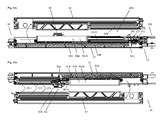
- FIG. 1 shows a sliding device with a drive according to the invention 1, which is guided along a running rail 2 and connected to a separating element 3, for example a glass plate.
- the drive 1, which is shown from the side, has a drive body 12, on the one hand two rollers 11 which rest on a lower rail member 211 of the track rail 2, and on the other hand via a coupling part 13 is connected to a mounting body 14.
- the mounting body 14 is laterally mounted by means of a connecting device 15 near the upper edge of the separating element 3.
- the coupling member 13 is slidably mounted in the drive body 12 parallel to the running direction of the drive 1 or parallel to the longitudinal axis of the track rail 2 and that upon displacement of the coupling member 13 is a displacement of the mounting body 14 slidably held by the drive body 12 perpendicular to Longitudinal axis of the running rail 2 takes place.
- the mounting body 14 is lifted by the coupling part 13, after which the coupling part 13 and the mounting body 14 by means of preferably two fixing elements 19, for example threaded bolts, are mutually fixed.
- the running rail 2 is shown in a preferred embodiment and has a downwardly open U-profile with a central piece 22 and a first and second side piece 21, 23.
- the first side piece 21 comprises the lower one Rail element 211 and a profile element 212, which serves to hold buffer devices 4A, 4B, which, as in FIG. 2a shown, are inserted into the slide rail 2.
- the second side piece 23 comprises two further profile elements 231, 232, which the in FIG. 11c and FIG. 13 shown stopper parts 6A, 6B, the operation of the in FIG. 1b and FIG. 11a shown feed device 5, which in the embodiment of the sliding device of FIG. 1a is not provided.
- the stop members 6A, 6B are configured plate-shaped and are inserted parallel to the second side piece 23 behind the profile parts 231, 232, and fixed for example by means of screws, which are held in a threaded bore 611 and front preferably have a ring cutting, which is rotated against the second side piece 23 becomes.
- a first stop part 6a is shown, which has a stop element 61 in the lower half, which projects into the cross section of the running rail 2.
- FIG. 11c and FIG. 13 shown stopper parts 6A, 6B, the operation of the in FIG. 1b and FIG. 11a shown feed device 5, which in the embodiment of the sliding device of FIG. 1a is not provided.
- the stop members 6A, 6B are configured plate
- FIG. 11c and FIG. 13 It is shown that the second stopper member 6B is inserted at the other end of the track rail 2 such that the stopper member 61 is provided at the top.
- a first intake unit 5A can be actuated at one end of the running rail 2
- a second intake unit 5B can be actuated by the second stopper part 6B at the other end of the running rail 2.
- the separating element 3 can therefore be automatically guided into the end stop in both end regions of the running rail 2 by means of the corresponding intake units 5A, 5B.
- the preferably identical intake units 5A, 5B will be described below with reference to FIGS FIGS. 12 a . 12b and 13 explained in more detail.
- the running rail 2 can in principle be reduced to this side piece 21, for example if the middle piece 22 for ceiling mounting of the running rail 2 and the second side piece 23 for mounting the stopper parts 6A, 6B are not needed.
- the reduced to the first side piece 21 running rail 2 can be bolted to a building wall, for example.
- FIG. 1a also shows two cutting lines A - A and B - B.
- the first section line A - A relates to a section through the running rail 2, the in FIG. 2a is shown.
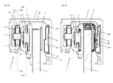
- the second section line B - B relates to a section through the drive body 12, the coupling part 13 and the mounting body 14, which in the Figures 10a and 10b is shown.
- FIG. 1a further shows that the track rail 2 above the lower rail member 211 has an upper rail member 221. Between the lower rail member 211 and the upper rail member 221 thus a running and guiding channel LFK is formed, as in FIG. 5a is illustrated. In the running and guide channel LFK the running elements of the drives 1A, 1B are performed. At the top of the lower rail member 211, a roller conveyor 2110 is provided, along which the guide rollers 11 of the drives are guided. On the underside of the upper sliding element 221, a guideway 2210 is provided, along which a sliding element 1281 is guided, which sits in the manner of a cap on a guide member 128 which is connected to the drive body 12 or molded around it.
- FIG. 1a It can be seen that the drive 1 can not be detached from the lower rail element 211 by a vertical force, a jolt or a shock.
- the drive body 12 For mounting and dismounting the drive 1, the drive body 12 is inclined laterally, so that the guide element 128 moves away from the upper rail element 221 of the running rail 2.
- the mounting body 14 is first connected to the separating element 3 and the drive body 12, as in FIG. 1a can be inserted into the running rail, after which the drive body 12 and the mounting body 14 can be connected to each other by means of the coupling part 13 in a simple manner.
- the assembly and disassembly of the drive 1 and the sliding door device therefore succeeds easily with simple measures.
- FIG. 1b shows the pusher of FIG. 1 , which is additionally connected to a collection device 5, which with the in FIGS. 1a and 11c shown stop parts 6A, 6B cooperates, which are held within the running rail 2.
- a collection device 5 which with the in FIGS. 1a and 11c shown stop parts 6A, 6B cooperates, which are held within the running rail 2.
- the dimensions of the device parts, in particular the running rail 2 do not change with the installation of the retraction device 5.
- the running rail 2 not only the upper end of the separating element 3 but in addition the retraction device 5 can be added without a larger cross-section of the running rail 2 is required.
- the collection device 5 can advantageously cooperate with the stop elements 6A, 6B used in the second side piece 23 of the running rail 2, which also take up only little space.
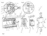
- FIG. 2a shows the pusher of FIG. 1b with two drives 1A, 1B, the collection device 5 and two buffer devices 4A, 4B, which are held in the track rail 2.
- the running rail 2 is along the in FIG. 1a shown line A - A cut. The cut passes through the middle piece 22 and through the lower rail element 211, on which the drives 1A, 1B rest, as well as through the overlying upper rail element 221 of the running rail 2.
- FIG. 2a shows that the drive 1A is supported at the bottom with the guide rollers 11 on the rail member 211 and above with the sliding member 1281, which is placed on the guide member 128, guided along the upper slide member 221.
- the running elements 11 and the sliding member 1281 are in the plane of the cut surface.
- any running elements such as rollers and sliding elements or combinations thereof and to move them laterally against each other.
- the arrangement in a plane is particularly advantageous because little space is required and the assembly and disassembly of the drives 1A and 1B is not hindered.
- the first drive 1A is coupled to the first buffering device 4a, which comprises a retaining spring 42, which has a buffering element 126, for example, a mounting hole 126 (see FIG FIG. 6a ) inserted in the drive body 12 bolts overlaps.
- the separating element 3 is therefore aligned in the end stop and with the front edge flush with the end of the running rail 2.
- the drives 1A, 1B according to the invention thus make it possible to adjust the separating element 3 without the separating element 3 shifting in the running direction.
- the separating element 3 can therefore be shifted in height and aligned horizontally and remains stationary in the running direction at the desired position within the running rail 2 at the same time.
- the collection device 5 is held by the first drive 1A, which in this preferred embodiment has an elongated mounting body 14 with a connecting element 149 which is detachably connected to a connecting part 59 of the collection device 5.
- the Feeding device 5 can therefore be optionally coupled to the first drive 1A and decoupled from it again.
- uniform drives 1 are used with identical mounting bodies 14, to which the collection device 5 can be coupled.
- FIG. 2b shows the pusher of FIG. 2a without track 2.
- Figure 2c shows the pusher of FIG. 2b with the separating element 3 detached from the drives 1A, 1B, which has two cylindrical mounting openings 31A, 31B for receiving the connecting device 15 and an elongated recess 32 for receiving the intake device 5.
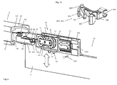
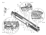
- FIG. 3 shows the first drive 1A coupled to the first buffer device 4A FIG. 2a in spatial representation. It is shown that the buffer device 4A has a buffer body 40 having a lower and an upper body part 401, 402, which can be held by the lower rail member 211 and the first profile element 212 of the first side piece 21 of the track rail 2.
- the retaining spring 42 which engages over the buffer element 126 inserted in the drive body 12, is fixed by means of a mounting screw 41, which is screwed into the buffer body 40.
- a mounting shaft 17 is also used, which rotatably supports a beam 18 in the middle.
- the beam 18 holds on both sides a roller axle 110 with a roller 11.
- the load acting on the drive 1A load is therefore divided evenly on both rollers 11.
- FIG. 3 further shows that the mounting member 14 can be moved vertically with the separating element 3 by a horizontal displacement of the coupling part 13. Furthermore, it is shown that the drive 1A has an extended mounting body 14 with a connecting element 149, which is provided with a mounting hole 1490. The collection device 5 can therefore be inserted into the recess 32 in the separating element 3 and connected by means of the connecting screw 1491 shown with the mounting body 14.
- FIG. 4 shows the drive 1A of FIG. 1a with dissolved mounting body 14 and elements of the connecting device 15, which are shown grouped in Figure 5c.
- the connecting device 15 includes the mounting bolt 151, a mounting bracket 152, a mounting cylinder 153, and a mounting nut 154.
- the mounting bracket 152 abuts an upper edge of the partition member 3 and covers a part of the back and top of the partition member 3.
- the mounting cylinder 153 has a cylinder member 1531, which is insertable into the mounting hole 31 A in the separating element 3 and to which a cylinder flange 1532 adjoins.
- the mounting nut 154 has a cylindrical threaded portion 1541, which is insertable into the mounting cylinder 151 and to which a flange 1542 adjoins the mounting cylinder 153 outside.
- FIG. 4a shows a detailed view of the mounting body 14 of FIG. 4 , the mounting body 14 is shown from the front with the mounting hole 145 into which the mounting screw 151 is inserted.
- FIG. 4b shows a detailed view of the second mounting hole 31 B in the separator 3.
- FIG. 5 shows the drive 1A of FIG. 1a in exploded view with those on the lower rail element 211 of the running rail 2 guided rollers 11, the drive body 12, the coupling part 13 and the mounting body 14, in which the mounting screw 151 is inserted, by means of which the drive 1A with the separating element 3 is connectable.
- the drive body 12 has a mounting hole 125 into which the mounting shaft 17 is inserted, which rotatably supports the beam 18 with the rollers 11.
- a mounting hole 29 in the first side piece 21 of the track rail 2 is shown, by means of which the track rail 2 can be mounted.
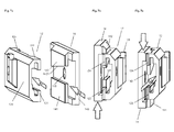
- the drive body 12 in the Figures 7a, 7b and 7c shown from different sides, comprises a drive plate 120 with first holding elements 121, 122 provided thereon in a first section and second holding elements 123, 124 in a second section separated therefrom.
- the two sections which have at least approximately the shape of a C-profile, delimit a first bearing channel K1.
- the mounting body 14, in the FIGS. 4a . 7a, 7b, 7c . 8b and 9b is shown from different sides, comprises a mounting plate 140, which has a lower and an upper retaining element 141, 142 and thereby also forms an at least approximately C-shaped section defining a second bearing channel K2.
- the upper retaining element 142 has on the underside a contact surface 1421 inclined to the running direction.
- the coupling part 13 which in the FIGS. 6a, 6b . 8a, 8b . 9a and 9b is shown from different sides, comprises a first coupling element 131 and a second coupling element 132, which are interconnected by a web 133 inclined to the running direction.
- the first coupling element 131 is held displaceably in the C-profile-shaped sections of the drive body 12 or in the first bearing channel K1.
- the second Coupling element 132 is slidably held in the C-profile-shaped portion of the mounting body 14 and in the second bearing channel K2.
- FIG. 9a It is shown that the upper side of the web 133 has a contact surface 1331, along which the upper retaining element 142 or the contact surface 1421 of the mounting plate 14 is displaceable.
- FIG. 5a shows a detailed view of the track 2 with the lower rail member 211, the top of which forms a roller conveyor 2110, and the upper rail member 221, the underside of which forms a guideway 2210.
- the rollers 11 of the drive 1A are guided.
- the sliding member 1281 held by the drive body 12 is guided in contact or with little play.
- a running and guiding channel LFK is formed, which receives the preferably arranged in a plane running elements 11, 1281 of the drive 1A and leads.
- a drive is thus provided which is guided on two sides in a running rail 2 by means of a lower rail element 211 and an upper rail element 221.
- this solution can also be applied to rails and drives that are designed symmetrically and Both sides are provided with running elements and rail elements.
- FIG. 5b shows the separate from the guide member 128 sliding member 1281 of FIG. 5a
- the sliding member 1281 is preferably made of a plastic having high lubricity.
- an upper guide roller could be provided, which can roll on the guide track 2210.
- FIGS. 6a and 6b show the drive body 12 and the mounting body 14, which are interconnected by the coupling part 13, whose first coupling element 131 is slidably held in the drive body 12 and the second coupling element 132 in the mounting body 14.
- the contact surface 1331 of the web 133 slides past the contact surface 1421 of the upper retaining element 142 of the mounting body 14 and displaces it vertically.
- FIG. 6a is further shown that the upper support member 142 of the mounting body 14 is held between the two upper support members 123, 124 of the drive body 12, so that the mounting body 14 can perform only a vertical movement with a displacement of the coupling part 13.
- first coupling element 131 of the coupling part 13 in the drive body 12 and in the first bearing channel K1 is only horizontally displaceable.
- the second coupling element 132 of the coupling part 13 is horizontally and vertically displaceable in the mounting body 14 or in the second bearing channel K2, as with reference to FIG. 9b will be described.
- the drive body 12 and the mounting body 14 and their mutual displacement are further in the Figures 7a, 7b and 7c illustrated.
- Figure 7a shows the drive body 12 and the mounting body 14 with the bearing channels K1 and K2, in which the coupling elements 131, 132 of the coupling part 13 can be inserted.
- FIGS. 7b and 7c show that the mutually facing holding elements 121, 122, 123, 124; 141, 142 of the drive body 12 and the mounting body 14 do not protrude into the first two bearing channels K1 and K2 in, but with little play next to each other and are therefore only vertically against each other.
- FIG. 7b is the mounting body 14 upwards and in FIG. 7c shifted down, while the drive body 12, which is held during operation of the running rail 2, has remained at the same level.
- the third bearing channel K3 Between the holding elements 121, 122, 123, 124 and 141, 142 of the drive body 12 and the mounting body 14 is the third bearing channel K3, in which the web 133 of the coupling part 13 is displaceable.
- FIG. 8a shows the inserted into the mounting body 14 coupling part 13 of FIG. 9a with cutting lines C - C and D - D.
- FIG. 8b shows the coupling part 13 and the mounting body 14 of FIG. 8a with a cut along the in FIG. 8a shown line CC.
- the holding elements 141 and 142 of the mounting body 14 and guided in the third bearing channel K3 web 133 are shown cut with hatching. It can be seen that the upper holding element 142 of the mounting element 14 is guided with the inclined contact surface 1421 on the parallel thereto contact surface 1331 of the web 133.
- the coupling part 13 is moved horizontally, the by the holding members 122 and 124 the drive body 12 vertically guided mounting body 14 up or under the load of the separating element 3 is moved downward.
- FIG. 9a shows the coupling part 13 of FIG. 8a in spatial representation.
- FIG. 9b shows the coupling part 13 and the mounting body 14 of FIG. 8a with a section along the line D - D.
- the second coupling element 132 of the coupling part 13 in the mounting body 14 and in the second bearing channel K2 is horizontally and vertically displaceable.
- the mounting body 14 can therefore be moved or adjusted by the appropriate amount down or up.
- the second coupling element 132 of the coupling part 13 can be fixed in a selected position.
- FIG. 10a and 10b show the drive 1B of FIG. 1a with a section along the line BB.
- the interaction of all three parts of the drive 1B can be seen, namely the drive body 12, the horizontally guided coupling part 13 and the vertically guided mounting body 14th
- FIG. 10a shows the coupling part 13 in a position in which the mounting body 14, as in FIG. 7b , was shifted vertically downwards.
- FIG. 10b shows the coupling part 13 in a position in which the mounting body 14, as in FIG. 7c , was shifted vertically upwards.
- FIG. 11a shows the separator 3 with the two drives 1A, 1B of FIG. 2a of which the first drive 1A or its mounting body 14 are connected to the collection device 5 is, which preferably has two superimposed feed units 5A, 5B.
- FIG. 11b shows the collection device 5 of FIG. 11a screwed to the mounting plate 14 of the drive 1A.
- FIG. 11c shows the stopper parts 6A and 6B of FIG. 1a in the mutual orientation in which they are mounted in the track 2. It can be seen that the stopper member 61 of the first stopper member 6A is positioned below and the stopper member 61 of the second stopper member 6B is positioned upward, so that the stopper members 6A and 6B can interact individually with the first and second retracting assemblies 5A, 5B.
- the Figures 12a and 12b show the advantageous construction of the feeder 5 with the two intake units 5A, 5B, which are separated by the housing 53 of the feeder 5 from each other.
- the housing 53 has on the underside a first device chamber 50A and on the upper side a second device chamber 50B, in each of which one of the intake units 5A, 5B are arranged.
- Each of the device chambers 50A and 50B can also be covered by an associated housing cover 51 or 53.
- FIG. 12a shows the bottom of the housing 53 and the top of the first housing cover 51, each having corresponding parts or tracks of a first guide slot 57A.
- a first locking unit 56A is guided on both sides with guide cams 567 and can be displaced from the position shown into a locking area 5701.
- the locking unit 56A which is in FIG. 14 is shown isolated, has a clamping lever 561, a trigger lever 562, a first holding part 564 for the pull-in spring 54A, a second holding part 565 for the intake damper 55A and, at the bottom and top in coaxial alignment, said guide cam 567 on.
- identical locking units 56A and 56B can be used (see FIGS Figures 13a and 13c ).
- the levers 561, 562, 563 of the locking units 56A, 56B protrude from the feeder 5 in the respective operating phases on the same side and can cooperate with the stopper parts 6A, 6B mounted on the same side piece 23 of the track rail 2.
- the locking unit 56A is connected by means of the first holding part 564 to a pull-in spring 54A and by means of the second holding part 565 to the plunger 551A of a pull-in damper 55A, which has a hydraulic cylinder 552A.
- the locking unit 56A is coupled in the position shown by means of the clamping lever 561 with a stationary mounted in the running rail stop member 6A.
- the pull-in spring 54A is relaxed.
- the separating element 3 is thus located in the in FIG. 2a shown end position in which the first drive 1A is coupled to the buffer device 4A.
- the locking unit 56A initially remains coupled to the abutment part 6A, for which reason the track 570 of the guide slot 57A slides past the guide cam 567 until the guide cams 567 are guided transversely to the running direction into the locking area 5701 and there being held. In this process, the locking unit 56A is rotated and decoupled from the stopper 6A. The cocking lever 561 is rotated against the device chamber 50A, and the trigger lever 562 is turned outward. During the shift of Locking unit 56 A in the locking portion 5701, the pull-in spring 5A was stretched and thus is in a state as for the pull-in spring 54 B of the second feed unit 5 B in FIG. 12b is shown.
- This second pull-in spring 54B was tensioned in the same manner until the associated lock unit 56B was decoupled from the associated stopper part 6B. While driving in the in FIG. 2a shown end position of the separating element 3, the locking unit 56 B was held in the locking portion 5701 and the pull-in spring 54 B stretched. The second intake unit 5B is ready for the intake operation in the region of the opposite second end stop.
- FIG. 12b shows the top of the housing 53 and the bottom of the second housing cover 52, each having corresponding parts or webs 570, 5701 a second guide slot 57B.
- the second lock unit 56B is guided, which is connected to a pull-in damper 55B and a pull-in spring 54B.
- the lock unit 57B is held in the lock portion 5701 and the pull-in spring 56B is cocked.
- the release lever 562 is rotated outwardly and can be detected by the associated stop member 6B, as soon as the separator 3 is moved into the corresponding catchment area.
- the lock unit 56B is rotated so that the cocking lever 561 also grasps the stopper member 6B, and the force of the disengaged take-in spring 54B can act on the stopper member 6B and move the separator member 3 to the end position.
- FIG. 13 shows the collection device 5 of FIG. 11a after disassembly of the housing 53 and the upper housing cover 52. It can be seen that the second intake unit 5B with the currently tensioned pull-in spring 54B above the first Feeding unit 5A is arranged and the first and second locking unit 56A; 56B at different heights with the associated abutment part 6A; 6B can interact.
- FIG. 13a shows the second locking unit 56B of FIG. 13 holding the tensioned second pull-in spring 54B in a first detail view from above.
- the locking unit 56B is retracted with the guide cam 567 along the slide track 570 in the locking portion 5701.
- the slide track 570 and the lock area 5701 are in FIG. 13b for the first intake unit 5A.
- the tensioning lever 561 is thus guided inwards and is no longer in the engagement area of the abutment part 6B.
- the release lever 562 is in the engagement region of the abutment part 6B and is detected by this, as soon as the separating element 3 is moved into its engagement region.
- first and the second holding part 564, 565 which hold the tensioned pull-in spring 54B and the plunger 551 of the retraction damper 55B. Furthermore, a holding member 58A is shown, which is integrally formed on the lower housing cover 51 and the relaxed first pull-in spring 54A holds.
- FIG. 13b shows the tail of the lower housing cover 51 of FIG. 13 in a second detail view with the lower slide track 570 of the first slotted guide 57A, which opens into the locking region 5701 and the end region undergoes a bend of approximately 90 °.
- FIG. 13c shows the coupled to the first stop member 6A first locking unit 6A in a third detail view. It is shown that the stopper member 61 of the first stopper member 6A is held between the trigger lever 562 and the cocking lever 561, which has been rotated outwardly upon impact of the trigger lever 562 on the stop member 6A.
- the safety lever 563 was also turned outwards. which fulfills an important security function. If the tensioning lever 561 does not gain or lose the coupling to the stop element 61, then the stop element 61 slides over a short distance to the securing lever 563 and is now held securely by the latter.
- the locking unit 56A can slide past the stop part 6A, for example, in the case of a disturbing external influence, and has to be manually re-hooked.
- the pull-in spring 54A is now discharged in the same way until the separating element 3 reaches the end stop. So that this also succeeds in the coupling to the safety lever 563, it is preferably provided that the pull-in spring 54A also has a residual stress in the end stop. The next trouble-free closing and opening of the separating element 3, the clamping lever 561 is automatically coupled to the stop member 6A again.
- FIG. 14 shows an example of one of the preferably identical locking units 56A, 56B in a spatial representation.
Landscapes
- Engineering & Computer Science (AREA)
- Mechanical Engineering (AREA)
- Platform Screen Doors And Railroad Systems (AREA)
- Bearings For Parts Moving Linearly (AREA)
- Automatic Assembly (AREA)
- Support Devices For Sliding Doors (AREA)
- Refuge Islands, Traffic Blockers, Or Guard Fence (AREA)
- Power-Operated Mechanisms For Wings (AREA)
Priority Applications (9)
| Application Number | Priority Date | Filing Date | Title |
|---|---|---|---|
| EP13178194.0A EP2829678B8 (fr) | 2013-07-26 | 2013-07-26 | Dispositif porte-roue réglable et dispositif coulissant |
| ES13178194.0T ES2627883T3 (es) | 2013-07-26 | 2013-07-26 | Mecanismo de rodadura ajustable y dispositivo deslizante |
| US14/297,003 US9009918B2 (en) | 2013-07-26 | 2014-06-05 | Adjustable carriage and shifting device |
| CA2853604A CA2853604C (fr) | 2013-07-26 | 2014-06-06 | Chariot reglable et dispositif de commutation |
| CL2014001831A CL2014001831A1 (es) | 2013-07-26 | 2014-07-10 | Carro para la sujecion y el desplazamiento de un elemento separador en una direccion de traslacion a lo largo de un riel de corredera, donde esta previsto una pieza de acoplamiento la que presenta un primer y un segundo elemento de acoplamiento, los que estan conectados entre si por una barra de union; dispositivo de deslizamiento. |
| KR1020140087373A KR102178224B1 (ko) | 2013-07-26 | 2014-07-11 | 조절 가능한 캐리지 및 시프팅 디바이스 |
| JP2014147098A JP6421917B2 (ja) | 2013-07-26 | 2014-07-17 | 調整可能なキャリッジ及びシフト装置 |
| AU2014206185A AU2014206185B2 (en) | 2013-07-26 | 2014-07-25 | Adjustable carriage and shifting device |
| CN201410359882.0A CN104340512B (zh) | 2013-07-26 | 2014-07-25 | 可调节的托架以及移动装置 |
Applications Claiming Priority (1)
| Application Number | Priority Date | Filing Date | Title |
|---|---|---|---|
| EP13178194.0A EP2829678B8 (fr) | 2013-07-26 | 2013-07-26 | Dispositif porte-roue réglable et dispositif coulissant |
Publications (3)
| Publication Number | Publication Date |
|---|---|
| EP2829678A1 true EP2829678A1 (fr) | 2015-01-28 |
| EP2829678B1 EP2829678B1 (fr) | 2017-03-08 |
| EP2829678B8 EP2829678B8 (fr) | 2017-06-28 |
Family
ID=48877100
Family Applications (1)
| Application Number | Title | Priority Date | Filing Date |
|---|---|---|---|
| EP13178194.0A Active EP2829678B8 (fr) | 2013-07-26 | 2013-07-26 | Dispositif porte-roue réglable et dispositif coulissant |
Country Status (9)
| Country | Link |
|---|---|
| US (1) | US9009918B2 (fr) |
| EP (1) | EP2829678B8 (fr) |
| JP (1) | JP6421917B2 (fr) |
| KR (1) | KR102178224B1 (fr) |
| CN (1) | CN104340512B (fr) |
| AU (1) | AU2014206185B2 (fr) |
| CA (1) | CA2853604C (fr) |
| CL (1) | CL2014001831A1 (fr) |
| ES (1) | ES2627883T3 (fr) |
Cited By (2)
| Publication number | Priority date | Publication date | Assignee | Title |
|---|---|---|---|---|
| EP3199078A1 (fr) * | 2016-02-01 | 2017-08-02 | Altura Leiden Holding B.V. | Séparation de douche comprenant une porte coulissante pouvant se déplacer dans des positions finales au moyen d'une unité d'amortisseurs à ressort |
| IT201900020904A1 (it) * | 2019-11-12 | 2021-05-12 | Metalglas Bonomi S R L | Sistema a pannelli mobili con dispositivo carrello |
Families Citing this family (27)
| Publication number | Priority date | Publication date | Assignee | Title |
|---|---|---|---|---|
| WO2014169771A1 (fr) * | 2013-04-15 | 2014-10-23 | Xu Jiangde | Dispositif de roue supérieure anti-rebondissement à amortissement à double tuyau |
| EP3020900B1 (fr) * | 2014-11-14 | 2018-09-05 | dormakaba Deutschland GmbH | Chariot à roulaux pour la réception d'une porte coulissante doté d'un dispositif de réglage en hauteur |
| DK3020901T3 (en) * | 2014-11-14 | 2022-02-07 | Dormakaba Deutschland Gmbh | Roller carriage for mounting a sliding door with at least two mounting devices |
| WO2016145370A1 (fr) * | 2015-03-11 | 2016-09-15 | Dirtt Environmental Solutions, Inc. | Porte à galandage |
| KR20170008417A (ko) * | 2015-07-14 | 2017-01-24 | 에스프린팅솔루션 주식회사 | 자동장착장치 및 이를 포함하는 화상형성장치 |
| CN105507720B (zh) * | 2016-01-18 | 2018-04-06 | 王胜利 | 一种双向阻尼器及其应用的移动门 |
| CN106255354A (zh) * | 2016-08-31 | 2016-12-21 | 江苏艾倍科科技股份有限公司 | 一种北斗三防终端 |
| CN106150248B (zh) * | 2016-08-31 | 2018-01-19 | 福建西河卫浴科技有限公司 | 一种插入式连接滑轮 |
| TWI616165B (zh) * | 2017-03-07 | 2018-03-01 | 川湖科技股份有限公司 | 用於可活動傢俱組件的回歸機構 |
| US9976329B1 (en) * | 2017-05-05 | 2018-05-22 | Caldwell Manufacturing Company North America, LLC | Adjustable carriage assembly for suspending a panel |
| US10450796B2 (en) * | 2017-06-08 | 2019-10-22 | Home Improvement Systems, Inc. | Sliding screen door |
| WO2019195150A1 (fr) * | 2018-04-02 | 2019-10-10 | Safran Cabin Inc. | Amortisseur de porte à fermeture automatique souple |
| WO2019232541A1 (fr) * | 2018-06-01 | 2019-12-05 | Splitt Enterprises Llc | Support de montage |
| AU2019229400B2 (en) * | 2018-10-15 | 2025-07-17 | Anthony Innovations Pty Ltd | Sliding Door Soft-Closer Device |
| US11421461B2 (en) * | 2018-10-15 | 2022-08-23 | Anthony Innovations Pty Ltd | Sliding door soft-closer device |
| AT521373B1 (de) * | 2018-11-13 | 2020-01-15 | Blum Gmbh Julius | Anordnung zur Führung einer Schiebetür |
| CN109681065B (zh) * | 2019-01-10 | 2024-06-04 | 广东东泰五金精密制造有限公司 | 一种家具滑动门的防跳式阻尼开闭结构 |
| DE102019216524B4 (de) * | 2019-07-31 | 2021-05-27 | Roto Frank Fenster- und Türtechnologie GmbH | Beschlaganordnung für einen parallelabstellbaren Flügel und Verschlussanordnung für eine Gebäudeöffnung |
| CN110482017B (zh) * | 2019-08-27 | 2024-04-09 | 广东拓斯达科技股份有限公司 | 一种板材移载装置 |
| AU2020389479B2 (en) * | 2020-04-17 | 2022-10-20 | Foshan Ideal Co., Ltd. | Shower door sliding mechanism for soft positioning |
| US11891847B2 (en) * | 2020-04-30 | 2024-02-06 | Dirtt Environmental Solutions Ltd. | Compact sliding door system with soft-close and locking functionality |
| SE544135C2 (en) * | 2020-05-04 | 2022-01-11 | Ikea Supply Ag | Sliding closet door assembly, bypass door assembly, and method for connecting a sliding door |
| CN112209303B (zh) * | 2020-11-05 | 2025-11-25 | 杭叉集团股份有限公司 | 搬运车货叉高度控制方法、装置及搬运车 |
| CA3140676C (fr) * | 2020-11-26 | 2023-12-05 | Ideal Sanitary Ware Co., Ltd. | Assemblage profil bas et porte coulissante |
| CN113167092A (zh) * | 2021-03-12 | 2021-07-23 | 佛山市爱迪尔卫浴有限公司 | 用于淋浴门的双向阻尼器 |
| ES1276864Y (es) * | 2021-07-20 | 2021-11-19 | Klein Iberica S A U | Dispositivo amortiguador de cierre y/o apertura para puertas correderas |
| EP4726158A1 (fr) | 2024-10-08 | 2026-04-15 | Hawa Sliding Solutions AG | Dispositif de rétraction, procédé de fabrication et dispositif de porte coulissante |
Citations (5)
| Publication number | Priority date | Publication date | Assignee | Title |
|---|---|---|---|---|
| FR2903446A1 (fr) * | 2006-07-07 | 2008-01-11 | S E E D Sarl | Dispositif porte-roue pour panneau coulissant,en particulier de porte |
| EP2151538A1 (fr) * | 2008-08-06 | 2010-02-10 | Hawa Ag | Dispositif avec un guide coulissant pour le support des panneaux, guide coulissant, rail de guidage et élément de séparation |
| EP2248976A1 (fr) * | 2009-04-28 | 2010-11-10 | Hawa Ag | Train de roulement pour le support d'un élément de séparation et élément de séparation |
| US7891052B2 (en) | 2006-10-19 | 2011-02-22 | Hawa Ag | Device with a carriage for holding panels and a separation element |
| EP2217782B1 (fr) | 2007-12-14 | 2012-02-29 | Eku Ag | Dispositif de traction et d'amortissement d'une porte coulissante logée dans un rail profilé pour le guidage de mécanismes de roulement, vers la position terminale |
Family Cites Families (26)
| Publication number | Priority date | Publication date | Assignee | Title |
|---|---|---|---|---|
| US2277316A (en) * | 1941-01-02 | 1942-03-24 | Oscar C Rixson Company | Door holder |
| US3630560A (en) * | 1970-11-12 | 1971-12-28 | Glynn Johnson Corp | Surface-mounted nonhanded door holder |
| JPH0347976U (fr) * | 1989-09-12 | 1991-05-07 | ||
| ES2084543B1 (es) * | 1993-03-26 | 1998-07-01 | Klein Iberica | Mecanismo para puertas corredizas de cristal. |
| AUPO689097A0 (en) * | 1997-05-20 | 1997-06-12 | Anthony Bearings Pty Ltd | Improved door adjustment mechanism |
| KR100573463B1 (ko) * | 1997-06-24 | 2006-04-24 | 하바 아게 | 미닫이문과 안내장치의 연결장치 |
| IL137707A0 (en) * | 1999-04-27 | 2001-10-31 | Hawa Ag | Suspension device |
| US7028370B2 (en) * | 2003-03-31 | 2006-04-18 | Thk Co., Ltd. | Retracting apparatus, drawer apparatus and sliding door apparatus |
| US20090100760A1 (en) * | 2004-04-22 | 2009-04-23 | Ewing K Bradley | Snap fit hanging panel and locking apparatus therefore |
| US7712258B2 (en) * | 2004-04-22 | 2010-05-11 | K. Bradley Ewing | Suspension and sill system for sliding members |
| JP2006045803A (ja) * | 2004-07-30 | 2006-02-16 | Shimodaira:Kk | 引戸の戸閉装置。 |
| DE102007038842A1 (de) * | 2007-08-16 | 2009-02-19 | Dorma Gmbh + Co. Kg | Schiebetüraufhängung |
| DE102008009046B4 (de) * | 2008-02-13 | 2014-10-02 | Günther Zimmer | Beschleunigungs- und Verzögerungsvorrichtung mit zwei Mitnahmeelementen |
| TWI392465B (zh) * | 2008-11-20 | 2013-04-11 | King Slide Works Co Ltd | 用於滑軌組件之自動回歸裝置 |
| EP2218858B1 (fr) * | 2009-02-15 | 2013-10-16 | Hawa Ag | Train de roulement pour un élément de séparation, élément de séparation et dispositif |
| DE102009042486A1 (de) * | 2009-09-24 | 2011-03-31 | Dorma Gmbh + Co. Kg | Schiebetür |
| ES2390717B1 (es) * | 2009-11-24 | 2013-10-03 | Masats, S.A. | Mecanismo para realizar el cierre y la apertura de una hoja de puerta oscilocorredera (swinging-sliding) |
| US8307497B2 (en) * | 2010-01-14 | 2012-11-13 | Door & Window Hardware Co. | Soft-closing device for a sliding door |
| JP4895318B2 (ja) * | 2010-02-24 | 2012-03-14 | 株式会社中尾製作所 | 引込装置 |
| JP5433466B2 (ja) * | 2010-03-17 | 2014-03-05 | 株式会社ニフコ | 摺動補助装置 |
| JP5285679B2 (ja) * | 2010-11-16 | 2013-09-11 | 株式会社中尾製作所 | 引込装置 |
| DE102011010778B4 (de) * | 2011-02-09 | 2017-03-23 | Günther Zimmer | Beschleunigungs- und Verzögerungsvorrichtung mit Mitnahmeelement-Schwenkgelenk sowie ein System mit zwei ein Zug- und Abbremsvorrichtungspaar bildende Beschleunigungs- und Verzögerungsvorrichtungen |
| JP5593287B2 (ja) | 2011-08-30 | 2014-09-17 | 株式会社ベスト | 引戸制動装置 |
| US8402606B1 (en) * | 2011-10-18 | 2013-03-26 | Patrick Tsai | Door closer with buffer mechanism for a sliding door |
| US20130160240A1 (en) * | 2011-12-23 | 2013-06-27 | Cavity Sliders Limited | Damping Assembly and Damping Mechanism Therefor |
| US8955195B2 (en) * | 2012-11-25 | 2015-02-17 | Door & Window Hardware Co. | Clamping-sliding assembly for a single-track-suspension sliding door |
-
2013
- 2013-07-26 ES ES13178194.0T patent/ES2627883T3/es active Active
- 2013-07-26 EP EP13178194.0A patent/EP2829678B8/fr active Active
-
2014
- 2014-06-05 US US14/297,003 patent/US9009918B2/en active Active
- 2014-06-06 CA CA2853604A patent/CA2853604C/fr active Active
- 2014-07-10 CL CL2014001831A patent/CL2014001831A1/es unknown
- 2014-07-11 KR KR1020140087373A patent/KR102178224B1/ko not_active Expired - Fee Related
- 2014-07-17 JP JP2014147098A patent/JP6421917B2/ja not_active Expired - Fee Related
- 2014-07-25 AU AU2014206185A patent/AU2014206185B2/en not_active Ceased
- 2014-07-25 CN CN201410359882.0A patent/CN104340512B/zh not_active Expired - Fee Related
Patent Citations (5)
| Publication number | Priority date | Publication date | Assignee | Title |
|---|---|---|---|---|
| FR2903446A1 (fr) * | 2006-07-07 | 2008-01-11 | S E E D Sarl | Dispositif porte-roue pour panneau coulissant,en particulier de porte |
| US7891052B2 (en) | 2006-10-19 | 2011-02-22 | Hawa Ag | Device with a carriage for holding panels and a separation element |
| EP2217782B1 (fr) | 2007-12-14 | 2012-02-29 | Eku Ag | Dispositif de traction et d'amortissement d'une porte coulissante logée dans un rail profilé pour le guidage de mécanismes de roulement, vers la position terminale |
| EP2151538A1 (fr) * | 2008-08-06 | 2010-02-10 | Hawa Ag | Dispositif avec un guide coulissant pour le support des panneaux, guide coulissant, rail de guidage et élément de séparation |
| EP2248976A1 (fr) * | 2009-04-28 | 2010-11-10 | Hawa Ag | Train de roulement pour le support d'un élément de séparation et élément de séparation |
Cited By (4)
| Publication number | Priority date | Publication date | Assignee | Title |
|---|---|---|---|---|
| EP3199078A1 (fr) * | 2016-02-01 | 2017-08-02 | Altura Leiden Holding B.V. | Séparation de douche comprenant une porte coulissante pouvant se déplacer dans des positions finales au moyen d'une unité d'amortisseurs à ressort |
| IT201900020904A1 (it) * | 2019-11-12 | 2021-05-12 | Metalglas Bonomi S R L | Sistema a pannelli mobili con dispositivo carrello |
| WO2021094855A1 (fr) * | 2019-11-12 | 2021-05-20 | Metalglas Bonomi S.R.L. | Système de panneaux mobiles à dispositif de chariot |
| US11788334B2 (en) | 2019-11-12 | 2023-10-17 | Metalglas Bonomi S.R.L. | Movable panels system with carriage device |
Also Published As
| Publication number | Publication date |
|---|---|
| KR20150013016A (ko) | 2015-02-04 |
| JP2015025356A (ja) | 2015-02-05 |
| KR102178224B1 (ko) | 2020-11-13 |
| US9009918B2 (en) | 2015-04-21 |
| ES2627883T3 (es) | 2017-07-31 |
| US20150026928A1 (en) | 2015-01-29 |
| CN104340512B (zh) | 2017-07-07 |
| EP2829678B8 (fr) | 2017-06-28 |
| CA2853604C (fr) | 2017-07-11 |
| AU2014206185A1 (en) | 2015-02-12 |
| AU2014206185B2 (en) | 2017-06-08 |
| JP6421917B2 (ja) | 2018-11-14 |
| CL2014001831A1 (es) | 2014-10-03 |
| EP2829678B1 (fr) | 2017-03-08 |
| CN104340512A (zh) | 2015-02-11 |
| CA2853604A1 (fr) | 2015-01-26 |
Similar Documents
| Publication | Publication Date | Title |
|---|---|---|
| EP2829678B1 (fr) | Dispositif porte-roue réglable et dispositif coulissant | |
| EP1959792B1 (fr) | Meuble presentant au moins des premiere et deuxieme parties de meuble | |
| EP3864245B1 (fr) | Dispositif d'entraînement pour deux positions d'extrémité | |
| EP2851496A1 (fr) | Dispositif de montage réglable pour un élément coulissant et dispositif coulissant | |
| EP3622149B1 (fr) | Rail de guidage d'un chariot d'une porte de meuble | |
| AT515690A4 (de) | Ausziehführung | |
| EP3029248B1 (fr) | Dispositif de coulissement pour un élément de séparation et pièce de meuble | |
| AT16936U1 (de) | Vorrichtung zum Bewegen einer Schiebetür oder Falt-Schiebetür | |
| EP4048122B1 (fr) | Combinaison d'un element de mouvement et d'un element de synchronisation pour des rails de tiroir | |
| EP3859110B1 (fr) | Ferrure de porte coulissante et procédé de déplacement d'un dispositif de commande | |
| EP2165868B1 (fr) | Système de porte coulissante pivotante | |
| EP3050773A1 (fr) | Dispositif d'aiguillage doté d'un verrou disposé entre les deux contre-aiguilles | |
| EP3201413B1 (fr) | Ensemble de ferrures | |
| EP2495382B1 (fr) | Dispositif de déplacement d'un battant d'une fenêtre, d'une porte ou analogue | |
| EP3088647B1 (fr) | Système à rails pour un dispositif de guidage | |
| EP1002916A1 (fr) | Serrure supplémentaire pour panneaux de portes, fenêtres ou similaires | |
| EP4083363A1 (fr) | Dispositif coulissant pour porte coulissante, agencement et dispositif d'entraînement | |
| EP2837763B1 (fr) | Butée de porte coulissante et mobilier | |
| EP4424960A1 (fr) | Dispositif de charnière, charnière de butée et unité fonctionnelle | |
| EP2527575B1 (fr) | Ferrure de porte coulissante | |
| EP3816383A1 (fr) | Agencement de porte coulissante | |
| EP1247931B1 (fr) | Commande de séquence de fermeture | |
| EP4532877B1 (fr) | Unité fonctionnelle dotée d'un compartiment de porte pour une porte maintenue coulissante | |
| DE19825071C2 (de) | Parallelausstellfenster mit Drehfunktion | |
| EP2690241B1 (fr) | Armature pour une porte coulissante à fermeture parallèle ou une fenêtre coulissante à fermeture parallèle |
Legal Events
| Date | Code | Title | Description |
|---|---|---|---|
| 17P | Request for examination filed |
Effective date: 20130726 |
|
| AK | Designated contracting states |
Kind code of ref document: A1 Designated state(s): AL AT BE BG CH CY CZ DE DK EE ES FI FR GB GR HR HU IE IS IT LI LT LU LV MC MK MT NL NO PL PT RO RS SE SI SK SM TR |
|
| AX | Request for extension of the european patent |
Extension state: BA ME |
|
| PUAI | Public reference made under article 153(3) epc to a published international application that has entered the european phase |
Free format text: ORIGINAL CODE: 0009012 |
|
| R17P | Request for examination filed (corrected) |
Effective date: 20150728 |
|
| RBV | Designated contracting states (corrected) |
Designated state(s): AL AT BE BG CH CY CZ DE DK EE ES FI FR GB GR HR HU IE IS IT LI LT LU LV MC MK MT NL NO PL PT RO RS SE SI SK SM TR |
|
| GRAP | Despatch of communication of intention to grant a patent |
Free format text: ORIGINAL CODE: EPIDOSNIGR1 |
|
| STAA | Information on the status of an ep patent application or granted ep patent |
Free format text: STATUS: GRANT OF PATENT IS INTENDED |
|
| INTG | Intention to grant announced |
Effective date: 20161207 |
|
| GRAS | Grant fee paid |
Free format text: ORIGINAL CODE: EPIDOSNIGR3 |
|
| GRAA | (expected) grant |
Free format text: ORIGINAL CODE: 0009210 |
|
| STAA | Information on the status of an ep patent application or granted ep patent |
Free format text: STATUS: THE PATENT HAS BEEN GRANTED |
|
| AK | Designated contracting states |
Kind code of ref document: B1 Designated state(s): AL AT BE BG CH CY CZ DE DK EE ES FI FR GB GR HR HU IE IS IT LI LT LU LV MC MK MT NL NO PL PT RO RS SE SI SK SM TR |
|
| REG | Reference to a national code |
Ref country code: GB Ref legal event code: FG4D Free format text: NOT ENGLISH |
|
| REG | Reference to a national code |
Ref country code: CH Ref legal event code: EP Ref country code: CH Ref legal event code: NV Representative=s name: PETER RUTZ, CH Ref country code: AT Ref legal event code: REF Ref document number: 873691 Country of ref document: AT Kind code of ref document: T Effective date: 20170315 |
|
| RAP2 | Party data changed (patent owner data changed or rights of a patent transferred) |
Owner name: HAWA SLIDING SOLUTIONS AG |
|
| REG | Reference to a national code |
Ref country code: IE Ref legal event code: FG4D Free format text: LANGUAGE OF EP DOCUMENT: GERMAN |
|
| REG | Reference to a national code |
Ref country code: DE Ref legal event code: R096 Ref document number: 502013006580 Country of ref document: DE |
|
| REG | Reference to a national code |
Ref country code: AT Ref legal event code: HC Ref document number: 873691 Country of ref document: AT Kind code of ref document: T Owner name: HAWA SLIDING SOLUTIONS AG, CH Effective date: 20170329 |
|
| REG | Reference to a national code |
Ref country code: LT Ref legal event code: MG4D |
|
| REG | Reference to a national code |
Ref country code: NL Ref legal event code: MP Effective date: 20170308 |
|
| REG | Reference to a national code |
Ref country code: FR Ref legal event code: PLFP Year of fee payment: 5 |
|
| PG25 | Lapsed in a contracting state [announced via postgrant information from national office to epo] |
Ref country code: HR Free format text: LAPSE BECAUSE OF FAILURE TO SUBMIT A TRANSLATION OF THE DESCRIPTION OR TO PAY THE FEE WITHIN THE PRESCRIBED TIME-LIMIT Effective date: 20170308 Ref country code: GR Free format text: LAPSE BECAUSE OF FAILURE TO SUBMIT A TRANSLATION OF THE DESCRIPTION OR TO PAY THE FEE WITHIN THE PRESCRIBED TIME-LIMIT Effective date: 20170609 Ref country code: NO Free format text: LAPSE BECAUSE OF FAILURE TO SUBMIT A TRANSLATION OF THE DESCRIPTION OR TO PAY THE FEE WITHIN THE PRESCRIBED TIME-LIMIT Effective date: 20170608 Ref country code: FI Free format text: LAPSE BECAUSE OF FAILURE TO SUBMIT A TRANSLATION OF THE DESCRIPTION OR TO PAY THE FEE WITHIN THE PRESCRIBED TIME-LIMIT Effective date: 20170308 Ref country code: LT Free format text: LAPSE BECAUSE OF FAILURE TO SUBMIT A TRANSLATION OF THE DESCRIPTION OR TO PAY THE FEE WITHIN THE PRESCRIBED TIME-LIMIT Effective date: 20170308 |
|
| REG | Reference to a national code |
Ref country code: ES Ref legal event code: FG2A Ref document number: 2627883 Country of ref document: ES Kind code of ref document: T3 Effective date: 20170731 |
|
| PG25 | Lapsed in a contracting state [announced via postgrant information from national office to epo] |
Ref country code: BG Free format text: LAPSE BECAUSE OF FAILURE TO SUBMIT A TRANSLATION OF THE DESCRIPTION OR TO PAY THE FEE WITHIN THE PRESCRIBED TIME-LIMIT Effective date: 20170608 Ref country code: SE Free format text: LAPSE BECAUSE OF FAILURE TO SUBMIT A TRANSLATION OF THE DESCRIPTION OR TO PAY THE FEE WITHIN THE PRESCRIBED TIME-LIMIT Effective date: 20170308 Ref country code: RS Free format text: LAPSE BECAUSE OF FAILURE TO SUBMIT A TRANSLATION OF THE DESCRIPTION OR TO PAY THE FEE WITHIN THE PRESCRIBED TIME-LIMIT Effective date: 20170308 Ref country code: LV Free format text: LAPSE BECAUSE OF FAILURE TO SUBMIT A TRANSLATION OF THE DESCRIPTION OR TO PAY THE FEE WITHIN THE PRESCRIBED TIME-LIMIT Effective date: 20170308 |
|
| PG25 | Lapsed in a contracting state [announced via postgrant information from national office to epo] |
Ref country code: NL Free format text: LAPSE BECAUSE OF FAILURE TO SUBMIT A TRANSLATION OF THE DESCRIPTION OR TO PAY THE FEE WITHIN THE PRESCRIBED TIME-LIMIT Effective date: 20170308 |
|
| PG25 | Lapsed in a contracting state [announced via postgrant information from national office to epo] |
Ref country code: SK Free format text: LAPSE BECAUSE OF FAILURE TO SUBMIT A TRANSLATION OF THE DESCRIPTION OR TO PAY THE FEE WITHIN THE PRESCRIBED TIME-LIMIT Effective date: 20170308 Ref country code: CZ Free format text: LAPSE BECAUSE OF FAILURE TO SUBMIT A TRANSLATION OF THE DESCRIPTION OR TO PAY THE FEE WITHIN THE PRESCRIBED TIME-LIMIT Effective date: 20170308 Ref country code: EE Free format text: LAPSE BECAUSE OF FAILURE TO SUBMIT A TRANSLATION OF THE DESCRIPTION OR TO PAY THE FEE WITHIN THE PRESCRIBED TIME-LIMIT Effective date: 20170308 Ref country code: RO Free format text: LAPSE BECAUSE OF FAILURE TO SUBMIT A TRANSLATION OF THE DESCRIPTION OR TO PAY THE FEE WITHIN THE PRESCRIBED TIME-LIMIT Effective date: 20170308 |
|
| PG25 | Lapsed in a contracting state [announced via postgrant information from national office to epo] |
Ref country code: PT Free format text: LAPSE BECAUSE OF FAILURE TO SUBMIT A TRANSLATION OF THE DESCRIPTION OR TO PAY THE FEE WITHIN THE PRESCRIBED TIME-LIMIT Effective date: 20170710 Ref country code: SM Free format text: LAPSE BECAUSE OF FAILURE TO SUBMIT A TRANSLATION OF THE DESCRIPTION OR TO PAY THE FEE WITHIN THE PRESCRIBED TIME-LIMIT Effective date: 20170308 Ref country code: IS Free format text: LAPSE BECAUSE OF FAILURE TO SUBMIT A TRANSLATION OF THE DESCRIPTION OR TO PAY THE FEE WITHIN THE PRESCRIBED TIME-LIMIT Effective date: 20170708 Ref country code: PL Free format text: LAPSE BECAUSE OF FAILURE TO SUBMIT A TRANSLATION OF THE DESCRIPTION OR TO PAY THE FEE WITHIN THE PRESCRIBED TIME-LIMIT Effective date: 20170308 |
|
| REG | Reference to a national code |
Ref country code: DE Ref legal event code: R097 Ref document number: 502013006580 Country of ref document: DE |
|
| PLBE | No opposition filed within time limit |
Free format text: ORIGINAL CODE: 0009261 |
|
| STAA | Information on the status of an ep patent application or granted ep patent |
Free format text: STATUS: NO OPPOSITION FILED WITHIN TIME LIMIT |
|
| PG25 | Lapsed in a contracting state [announced via postgrant information from national office to epo] |
Ref country code: DK Free format text: LAPSE BECAUSE OF FAILURE TO SUBMIT A TRANSLATION OF THE DESCRIPTION OR TO PAY THE FEE WITHIN THE PRESCRIBED TIME-LIMIT Effective date: 20170308 |
|
| 26N | No opposition filed |
Effective date: 20171211 |
|
| PG25 | Lapsed in a contracting state [announced via postgrant information from national office to epo] |
Ref country code: SI Free format text: LAPSE BECAUSE OF FAILURE TO SUBMIT A TRANSLATION OF THE DESCRIPTION OR TO PAY THE FEE WITHIN THE PRESCRIBED TIME-LIMIT Effective date: 20170308 |
|
| REG | Reference to a national code |
Ref country code: IE Ref legal event code: MM4A |
|
| PG25 | Lapsed in a contracting state [announced via postgrant information from national office to epo] |
Ref country code: IE Free format text: LAPSE BECAUSE OF NON-PAYMENT OF DUE FEES Effective date: 20170726 |
|
| PG25 | Lapsed in a contracting state [announced via postgrant information from national office to epo] |
Ref country code: LU Free format text: LAPSE BECAUSE OF NON-PAYMENT OF DUE FEES Effective date: 20170726 |
|
| REG | Reference to a national code |
Ref country code: FR Ref legal event code: PLFP Year of fee payment: 6 |
|
| REG | Reference to a national code |
Ref country code: CH Ref legal event code: PCAR Free format text: NEW ADDRESS: ALPENSTRASSE 14 POSTFACH 7627, 6302 ZUG (CH) |
|
| PG25 | Lapsed in a contracting state [announced via postgrant information from national office to epo] |
Ref country code: MT Free format text: LAPSE BECAUSE OF FAILURE TO SUBMIT A TRANSLATION OF THE DESCRIPTION OR TO PAY THE FEE WITHIN THE PRESCRIBED TIME-LIMIT Effective date: 20170308 |
|
| PG25 | Lapsed in a contracting state [announced via postgrant information from national office to epo] |
Ref country code: MC Free format text: LAPSE BECAUSE OF FAILURE TO SUBMIT A TRANSLATION OF THE DESCRIPTION OR TO PAY THE FEE WITHIN THE PRESCRIBED TIME-LIMIT Effective date: 20170308 Ref country code: HU Free format text: LAPSE BECAUSE OF FAILURE TO SUBMIT A TRANSLATION OF THE DESCRIPTION OR TO PAY THE FEE WITHIN THE PRESCRIBED TIME-LIMIT; INVALID AB INITIO Effective date: 20130726 |
|
| PG25 | Lapsed in a contracting state [announced via postgrant information from national office to epo] |
Ref country code: CY Free format text: LAPSE BECAUSE OF FAILURE TO SUBMIT A TRANSLATION OF THE DESCRIPTION OR TO PAY THE FEE WITHIN THE PRESCRIBED TIME-LIMIT Effective date: 20170308 |
|
| PG25 | Lapsed in a contracting state [announced via postgrant information from national office to epo] |
Ref country code: MK Free format text: LAPSE BECAUSE OF FAILURE TO SUBMIT A TRANSLATION OF THE DESCRIPTION OR TO PAY THE FEE WITHIN THE PRESCRIBED TIME-LIMIT Effective date: 20170308 |
|
| PG25 | Lapsed in a contracting state [announced via postgrant information from national office to epo] |
Ref country code: TR Free format text: LAPSE BECAUSE OF FAILURE TO SUBMIT A TRANSLATION OF THE DESCRIPTION OR TO PAY THE FEE WITHIN THE PRESCRIBED TIME-LIMIT Effective date: 20170308 |
|
| PG25 | Lapsed in a contracting state [announced via postgrant information from national office to epo] |
Ref country code: AL Free format text: LAPSE BECAUSE OF FAILURE TO SUBMIT A TRANSLATION OF THE DESCRIPTION OR TO PAY THE FEE WITHIN THE PRESCRIBED TIME-LIMIT Effective date: 20170308 |
|
| P01 | Opt-out of the competence of the unified patent court (upc) registered |
Effective date: 20230529 |
|
| PGFP | Annual fee paid to national office [announced via postgrant information from national office to epo] |
Ref country code: IT Payment date: 20230724 Year of fee payment: 11 Ref country code: GB Payment date: 20230720 Year of fee payment: 11 Ref country code: ES Payment date: 20230926 Year of fee payment: 11 |
|
| PGFP | Annual fee paid to national office [announced via postgrant information from national office to epo] |
Ref country code: FR Payment date: 20230725 Year of fee payment: 11 Ref country code: BE Payment date: 20230719 Year of fee payment: 11 |
|
| GBPC | Gb: european patent ceased through non-payment of renewal fee |
Effective date: 20240726 |
|
| PG25 | Lapsed in a contracting state [announced via postgrant information from national office to epo] |
Ref country code: BE Free format text: LAPSE BECAUSE OF NON-PAYMENT OF DUE FEES Effective date: 20240731 |
|
| PG25 | Lapsed in a contracting state [announced via postgrant information from national office to epo] |
Ref country code: FR Free format text: LAPSE BECAUSE OF NON-PAYMENT OF DUE FEES Effective date: 20240731 |
|
| PG25 | Lapsed in a contracting state [announced via postgrant information from national office to epo] |
Ref country code: GB Free format text: LAPSE BECAUSE OF NON-PAYMENT OF DUE FEES Effective date: 20240726 |
|
| REG | Reference to a national code |
Ref country code: BE Ref legal event code: MM Effective date: 20240731 |
|
| PG25 | Lapsed in a contracting state [announced via postgrant information from national office to epo] |
Ref country code: IT Free format text: LAPSE BECAUSE OF NON-PAYMENT OF DUE FEES Effective date: 20240726 |
|
| REG | Reference to a national code |
Ref country code: ES Ref legal event code: FD2A Effective date: 20250904 |
|
| PG25 | Lapsed in a contracting state [announced via postgrant information from national office to epo] |
Ref country code: ES Free format text: LAPSE BECAUSE OF NON-PAYMENT OF DUE FEES Effective date: 20240727 |
|
| PGFP | Annual fee paid to national office [announced via postgrant information from national office to epo] |
Ref country code: DE Payment date: 20250722 Year of fee payment: 13 |
|
| PGFP | Annual fee paid to national office [announced via postgrant information from national office to epo] |
Ref country code: AT Payment date: 20250722 Year of fee payment: 13 |
|
| PGFP | Annual fee paid to national office [announced via postgrant information from national office to epo] |
Ref country code: CH Payment date: 20250801 Year of fee payment: 13 |