EP2829791A1 - KFZ-Beleuchtungs- und/oder Signalmodul - Google Patents
KFZ-Beleuchtungs- und/oder Signalmodul Download PDFInfo
- Publication number
- EP2829791A1 EP2829791A1 EP14178161.7A EP14178161A EP2829791A1 EP 2829791 A1 EP2829791 A1 EP 2829791A1 EP 14178161 A EP14178161 A EP 14178161A EP 2829791 A1 EP2829791 A1 EP 2829791A1
- Authority
- EP
- European Patent Office
- Prior art keywords
- module
- primary
- light source
- light
- optical system
- Prior art date
- Legal status (The legal status is an assumption and is not a legal conclusion. Google has not performed a legal analysis and makes no representation as to the accuracy of the status listed.)
- Withdrawn
Links
- 230000011664 signaling Effects 0.000 title claims abstract description 15
- 230000003287 optical effect Effects 0.000 claims abstract description 31
- 238000005286 illumination Methods 0.000 claims description 8
- 238000005401 electroluminescence Methods 0.000 claims description 6
- 230000015572 biosynthetic process Effects 0.000 description 4
- 239000007787 solid Substances 0.000 description 3
- 239000000470 constituent Substances 0.000 description 2
- 238000003306 harvesting Methods 0.000 description 2
Images




Classifications
-
- F—MECHANICAL ENGINEERING; LIGHTING; HEATING; WEAPONS; BLASTING
- F21—LIGHTING
- F21S—NON-PORTABLE LIGHTING DEVICES; SYSTEMS THEREOF; VEHICLE LIGHTING DEVICES SPECIALLY ADAPTED FOR VEHICLE EXTERIORS
- F21S43/00—Signalling devices specially adapted for vehicle exteriors, e.g. brake lamps, direction indicator lights or reversing lights
- F21S43/40—Signalling devices specially adapted for vehicle exteriors, e.g. brake lamps, direction indicator lights or reversing lights characterised by the combination of reflectors and refractors
-
- F—MECHANICAL ENGINEERING; LIGHTING; HEATING; WEAPONS; BLASTING
- F21—LIGHTING
- F21S—NON-PORTABLE LIGHTING DEVICES; SYSTEMS THEREOF; VEHICLE LIGHTING DEVICES SPECIALLY ADAPTED FOR VEHICLE EXTERIORS
- F21S43/00—Signalling devices specially adapted for vehicle exteriors, e.g. brake lamps, direction indicator lights or reversing lights
- F21S43/10—Signalling devices specially adapted for vehicle exteriors, e.g. brake lamps, direction indicator lights or reversing lights characterised by the light source
- F21S43/13—Signalling devices specially adapted for vehicle exteriors, e.g. brake lamps, direction indicator lights or reversing lights characterised by the light source characterised by the type of light source
- F21S43/14—Light emitting diodes [LED]
-
- F—MECHANICAL ENGINEERING; LIGHTING; HEATING; WEAPONS; BLASTING
- F21—LIGHTING
- F21S—NON-PORTABLE LIGHTING DEVICES; SYSTEMS THEREOF; VEHICLE LIGHTING DEVICES SPECIALLY ADAPTED FOR VEHICLE EXTERIORS
- F21S43/00—Signalling devices specially adapted for vehicle exteriors, e.g. brake lamps, direction indicator lights or reversing lights
- F21S43/30—Signalling devices specially adapted for vehicle exteriors, e.g. brake lamps, direction indicator lights or reversing lights characterised by reflectors
- F21S43/31—Optical layout thereof
Definitions
- the invention relates to a lighting and / or signaling module, in particular for a motor vehicle.
- the invention also relates to a lighting and / or signaling device comprising such a module.
- Patent documents US 2005/0259431 A1 and JP 2003-229006 A disclose a lighting module illustrated in the figure 1 of this document.
- the module 2 comprises a light source S of the electroluminescence diode type illuminating in a half-space delimited by the support of the diode, a first elliptical reflecting surface of revolution 4 and a second parabolic reflecting surface of revolution 6.
- the first elliptical reflecting surface of revolution 4 comprises a first focus F1 coincides with the light source S, and a second focus F2 coincides with the focus of the second parabolic reflective surface of revolution 6.
- the light rays emitted by the light source S are reflected by the elliptical reflective surface to the second focus F2 of said surface, it being understood that the hearth forms a ring in view of the fact that said surface is of revolution.
- the rays reflected by the elliptical surface 4 and passing through the second focus F2 of the elliptical surface 4 are then reflected by the parabolic surface along the optical axis of the parabolic surface.
- the lighting module produces an annular light beam.
- the at least approximate concordance of the second focus of the first elliptical reflective surface with the focus of the second parabolic reflective surface in the area delimited by the two reflective surfaces is not without some difficulties.
- the object of the invention is to propose a lighting and / or signaling module that overcomes at least one of the abovementioned disadvantages. More particularly, the invention aims to provide a lighting and / or signaling module capable of emitting a light beam shaped curve and inexpensive to achieve. The invention also aims to provide a lighting and / or signaling module with greater lighting power without increasing the cost of production and / or size.
- the subject of the invention is a vehicle light module capable of forming a light beam of road lighting and / or signaling and / or lighting of the interior of the passenger compartment of the vehicle, said module comprising: at least one light source; at least one primary reflective surface; an optical system; the primary reflective surface (s) being configured to reflect rays directly from the light source (s) to the optical system forming the light beam; remarkable in that the or each of the primary reflective surfaces is generally flat or convex so as to form a virtual image of the light source or sources.
- the optical system comprises at least one focus and the virtual image (s) of the light source (s) is (are) positioned at said focus or at said focus respectively.
- the light source (s), preferably of the electroluminescence diode type, illuminate in a main direction and the primary reflective surface (s) and the optical system are configured so that the main direction of the light beam of the module is generally parallel to the main illumination direction of the light source or sources and said light beam is shifted transversely relative to said main direction.
- the primary reflective surface or surfaces are convex opposite the light source or sources.
- the primary reflective surface or surfaces have a hyperbolic profile, one of which is located on the one or more of the light sources.
- the or each of the primary reflecting surfaces is a surface of revolution over at least a fraction of a turn, said surface preferably being a surface of revolution over a complete revolution.
- the module comprises at least two adjacent primary reflective surfaces.
- the module comprises at least three adjacent primary reflecting surfaces (104; 304) sequentially distributed and joining so as to form a funnel with walls whose outer surface is formed by the first surfaces.
- the virtual image is positioned between the walls of the funnel formed by the primary reflecting surfaces.
- the module comprises several light sources including at least one primary reflective surface.
- the primary reflective surfaces can be arranged to form a plurality of virtual images offset from one another.
- Each of the virtual images may be formed bijectively by the one or more primary reflective surfaces and the one or more light sources.
- bijective it is meant that a single virtual image is associated with a single light source / primary reflective surface pair, this pair being itself associated only with this single virtual image.
- the light sources may be arranged in the same plane, in particular carried by the same electronic card and / or carried by a tertiary reflecting surface.
- the module comprises a main axis, the light sources being disposed at a distance from said axis along a circle or a circular arc centered on said axis.
- the optical system comprises at least one secondary reflecting surface arranged to deflect the rays reflected by the primary reflective surface (s).
- the reflective surface or surfaces have a parabolic profile.
- the module comprises at least two adjacent secondary reflective surfaces with a parabolic profile, the module preferably comprising at least three adjacent secondary reflective surfaces with a parabolic profile distributed along a curve forming a circle or an arc of circle.
- each of the secondary reflecting surfaces is optically disposed opposite a corresponding primary reflecting surface.
- the or each of the secondary reflecting surfaces is a surface of revolution over at least a fraction of a turn, said surface preferably being a surface of revolution over a complete revolution.
- the module comprises a tertiary reflecting surface extending between the primary reflective surface (s) and the optical system, at the level of the light source (s), said tertiary surface being arranged in such a way as to reflect the rays coming directly from the light source (s) and / or the at least one of the primary reflecting surfaces and which are not received by the optical system, said tertiary surface being preferably generally flat.
- the primary reflective surface (s) are in contact with the tertiary reflecting surface, the primary reflective surface (s) more preferably comprising an adjacent reflective surface portion and generally perpendicular to the third surface. This portion of surface generally perpendicular to the third surface makes it possible to recover rays coming directly laterally from the light source or sources which otherwise would never reach the optical system.
- the primary reflective surface (s) and the optical system extend generally circularly, preferably over a complete turn, around a main axis of the module, the module comprising several light sources arranged at distance from said axis along an arc of a circle centered on said axis.
- the module comprises a central cavity extending along the main axis of the module from the first surface to the opposite end of the optical system, said cavity emitting no light .
- the invention also relates to a vehicle light device comprising a light module, characterized in that the module is in accordance with the invention.
- the measures of the invention make it possible to produce a module producing a beam offset laterally while limiting the space required.
- the embodiment of the module by means of a plane primary reflective surface is particularly economical, in particular in comparison with the elliptical surface of the state of the art.
- the configuration with a series of planar or hyperbolic primary reflective surfaces makes it possible to house several light sources and thus produce a more powerful beam for a given module size.
- the arrangement of the light sources along a circle at a distance from the main axis of the module makes it possible to reserve a passage through the module. Such a passage may be particularly useful for housing another module and / or for passing the power cables of such another module.
- the constituent optical elements of the lighting modules and / or signaling are shown schematically and simplified for the sake of clarity of presentation.
- the light sources which are preferably of the electroluminescence diode type, are represented by dots.
- Reflective surfaces having one or more foci and cooperating with each other with certain focal points are represented in certain illustrations of principle by simple lines, omitting to represent their necessary thickness.
- the concordant foci are represented in complete correspondence whereas in reality a certain tolerance of concordance is necessary, taking into account, in particular, the mounting tolerances of the various elements as well as inaccuracies in the production of these surfaces and, consequently, of their fireplace (s). The description that follows must therefore be interpreted in the light of these comments.
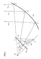
- the figure 2 illustrates a first principle of forming a virtual image of a light source by means of a planar reflector, this first principle forming the basis of a first embodiment of the invention.
- the light source S illuminates essentially in a half-space directed towards the upper part of the figure, more particularly in a solid angle oriented upwards.
- a first generally planar reflecting surface 104 is inclined with respect to the main direction of the solid illumination angle of the light source S. The rays of the light source S are thus reflected by the first reflective surface 104 to a second reflective surface 106 disposed laterally or outwardly of the first reflective surface.
- the second reflective surface is of parabolic profile with a focus F positioned at the rear of the first reflecting surface 104, more particularly where the first reflecting surface 104 forms a virtual image S 'of the light source S.
- the rays emitted by the light source and meeting the first plane luminous surface 104 are reflected according to the general principle of Snell-Descartes reflection with a reflection angle equal to the angle of incidence, the angles of reflection and incidence being measured in relation to the normal to the reflection surface passing through the point of incidence.
- FIG. 2 Three rays are illustrated at figure 2 to illustrate the formation of a virtual image S 'of the light source S.
- every ray of light passing through the focus of a parabola and meeting it is reflected in a direction parallel to the axis of the parabola.
- the extension of the ray reflected towards the rear of the reflector 104 shown in dashed lines converges towards the point S 'of the virtual image of the light source.
- the angle 90 ° - ⁇ that forms the extension of the ray reflected with the reflective surface is identical to the angle 90 ° - ⁇ that forms the incident ray with the same surface.
- the same is true for the second ray 110 which encounters the first reflecting surface 104 at a point of incidence B and then the second reflecting surface 106 at a first point of incidence B ', as well as for the third ray 112 which encounters the first reflecting surface at a first point of incidence C and the second reflecting surface at a second point of incidence C '.
- the virtual image S 'thus corresponds to the symmetry of the light source with respect to the plane of the reflecting surface, in the manner of a plane of symmetry. This arrangement makes it possible to offset a light beam laterally in a compact and optimized manner. Indeed, the virtual image is formed at the rear of the first reflective surface, which allows to size the second reflective surface larger than if the focus of this surface was to be disposed between the first and second reflective surfaces.
- the Figures 3 and 4 illustrate a first embodiment of a lighting and / or signaling module according to the invention and applying the principle illustrated in FIG. figure 2 .
- the figure 3 is seen in elevation of the module and the figure 4 is a sectional view along the axis 4-4 of the figure 3 .
- the module 102 essentially comprises a first reflector 116 with five planar primary reflective surfaces distributed around the main axis 114 of the module. It also comprises five electroluminescence diode-type light sources S, the diodes being arranged facing the flat primary reflective surfaces 104 of the first reflector 116.
- the light sources S illuminate in a half-space oriented along the main illumination direction 126.
- the module also comprises a second reflector 118 disposed laterally or externally to the first reflector, comprising five parabolic secondary reflecting surfaces 106 respectively facing the flat primary reflective surfaces 104 of the first reflector 116.
- the secondary parabolic reflective surfaces 106 of the second reflector are preferably surfaces of revolution about an axis passing through the pair S-S ', namely the light source and its virtual image. Indeed, with reference to explanations of the phenomenon explained above in relation to the figure 2 , the rays emitted by the light source S and meeting the reflecting surface 104 will be reflected to the secondary reflecting surface 106 while forming a virtual image S 'of the light source S. In other words, the secondary reflecting surface 106 sees the incident rays reflected by the primary reflecting surface as if they originated directly from the virtual image S 'located behind the reflecting surface.
- the module 102 may also comprise a Fresnel lens 120 as well as a transparent cover 122.
- the second reflector 118 and the Fresnel lens constitute an optical system capable of harvesting the light rays reflected by the first reflector 116 and forming a light beam in a direction 128 generally parallel to the main axis 114 of the module 102.
- the module 102 may also comprise a third reflector 124 disposed generally transversely, preferably perpendicular to the main axis 114 of the module 102.
- This third reflector 124 extends from the first reflector 116 to the second reflector so as to reflect the rays. which would otherwise be lost, that is to say the rays coming directly from the light source S or coming directly from the first reflector and not reaching the second reflector 118.
- the first reflector 116 comprises, in addition to the flat primary reflective surfaces 104 inclined relative to the third reflector 124, flat surface portions 104a generally perpendicular to said third reflector 124. These surface portions are substantially smaller in size than the surfaces. 104.
- the surface portions 104a are intended to reflect the rays coming directly from the light source and which otherwise would not reach the second reflector 118. Indeed, the rays emitted laterally by the light source S, such as a ray generally horizontal and oriented towards the main axis 114 would, in the absence of this surface portion 104a, reflected by the first reflector towards the third reflector. Depending on the dimensioning of the module, the reflected ray could again meet the first reflector at a point of incidence located higher. These multiple reflections are the seat of losses and confer, moreover, a great uncertainty as to the trajectory of the ray.
- the module may comprise a single light source centered on the main axis of the module. If the planar primary reflecting surfaces 104 are arranged so that the virtual image of the light source is also located on the main axis, the reflecting surface 106 of the second reflector 118 can be of revolution without inflection with respect to several portions. In fact, if the light source S and its virtual image S 'are aligned with the main axis 114, the reflecting surface 106 of the second reflector 118 can then be formed by the rotation of a parabolic profile around said axis.
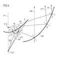
- the figure 5 illustrates a second principle of forming a virtual image of a light source by means of a hyperbolic reflector, this second principle forming the basis of a second and third embodiment of the invention.
- the light source S illuminates essentially in a half-space directed towards the upper part of the figure, more particularly in a solid angle oriented upwards.
- a first reflective surface 204 of the hyperbolic type is disposed in the illumination field of the light source.
- Hyperbole 204 is by definition the locus of points whose difference in distances to the two foci F 1 and F 2 is constant.
- the focal axis 114 is the name of the straight line carrying the two foci F 1 and F 2 : it is an axis of symmetry of the hyperbola, this axis intersecting the hyperbola. For this reason, it is also called transverse axis and its common points with the curve are the vertices.
- the bisector of the angular sector F 1 MF 2 happens to be the tangent in M to the curve.
- a second reflective surface 206 of the parabolic type is disposed opposite the first reflecting surface 204.
- the parabolic reflecting surface 206 comprises a focus which coincides with the focus F 1 of the first reflecting surface, namely the focus of this surface which is located in its concavity.
- the light source is disposed at the focus F 2 of the hyperbola with respect to which the curve is convex.
- the hyperbolic reflecting surface by reflecting the rays emitted by the light source, forms a virtual image S 'of the light source S at the location of the focus F 1 .
- a first ray 208 emitted by the light source S is illustrated in FIG. figure 5 . It meets the reflective surface 204 at a first point of incidence A at an angle of incidence 5 with respect to the normal N to the tangent T at the hyperbolic profile at point A. It follows from the general principle of reflection of Snell-Descartes that the incident ray at point A will be reflected at an angle of reflection s with respect to the normal N, which is equal to the angle of incidence ⁇ . The reflected ray then meets the second reflective surface 206 at a second point of incidence A 'to be reflected along the optical axis of the dish.
- the extension of the ray 208 reflected by the first reflective surface towards the rear of the reflecting surface is illustrated in dotted lines. It meets the focus F 1 of hyperbole. Indeed, if we consider the triangle formed by the foci F 1 and F 2 and the point of incidence A, the tangent T to the hyperbola is the bisector of the angle F 1 AF 2 . This characteristic is intrinsic to the definition of a hyperbola, as has been explained previously. It follows from this characteristic that the angles ⁇ and ⁇ are equal.
- a second and a third radius 210 and 212 are illustrated: the ray 210 meets the hyperbola at a first point of incidence B, is reflected towards the parabola that it encounters at a second point of incidence B 'and is reflected according to a direction generally parallel to the corresponding radius 208 along the optical axis of the parable. The same is true for the third ray 212 which encounters the reflective surfaces at respective incidence points C and C '.
- the optical principle that has just been described in relation to the figure 5 makes it possible to return a large part of the rays emitted by the light source to an optical system such as a parabolic reflector.
- the latter reflects the rays along its optical axis.
- the light beam produced is consequently offset laterally with respect to the main illumination direction of the light source.
- the hyperbolic surface makes it possible to form a virtual image of the light source and hence a larger dimensioning of the parabola.
- the hyperbolic surface may be symmetrical in revolution, which produces an annular light beam.
- FIGS. 6 and 7 illustrate a lighting and / or signaling module 202 according to a second embodiment of the invention, applying the principle which has just been detailed in relation to the figure 5 .
- the figure 6 is an elevational view of module 202 and the figure 7 is a sectional view of the module along the axis 7-7 of the figure 6 .
- the module 202 essentially comprises a first reflector 216 with a primary hyperbolic reflective surface 204.
- This hyperbolic surface is characterized by two foci, namely a first focus F 1 located in the concave portion of the curve and a second focus F 2 located in the convex part. These two foci form the axis of symmetry of the curve and are aligned with the main axis 214 of the module 202.
- the first reflective surface 204 is preferably a surface of revolution.
- a light source S is disposed at the location of the second focus F 2 . It is arranged to illuminate essentially in a half-space directed towards the upper part of the figure.
- the main illumination direction 226 of the source S coincides with the main axis 214 of the module.
- the rays emitted by the light source are reflected by the primary reflecting surface towards a second reflector 218.
- the latter essentially comprises a secondary reflective surface of parabolic profile whose focus coincides with the first focus F 1 of the hyperbolic surface and the image virtual S 'of the light source.
- the module 202 may also include a Fresnel lens 220 and a transparent cover 222.
- the second reflector 218 and the Fresnel lens 220 constitute an optical system capable of harvesting the light rays reflected by the first reflector 216 and to form a light beam in a direction 228 generally parallel to the main axis 214 of the module 202.
- the module 202 may also comprise a third reflector 224 disposed generally transversely, preferably perpendicularly to the main axis 214 of the module 202.
- This third reflector 224 extends from the first reflector 216 to the second reflector so as to reflect the rays that would otherwise be lost, that is to say the rays coming directly from the light source S or directly from the first reflector and not reaching the second reflector 218.
- the module 202 is preferably symmetrical in revolution with respect to the main axis 214. Indeed, the fact that the first and second foci of the hyperbola are aligned with the main axis of the module makes it possible to provide the primary and secondary reflective surfaces. symmetrical in revolution over 360 ° with respect to said axis.
- the figure 8 illustrates a third embodiment of the invention which corresponds to a variation of the second embodiment of the invention, incorporating certain features of the first embodiment.
- the figure 8 is a sectional view of a module 302 along the axis 7-7 of the figure 6 this latter also corresponds to an elevational view of said module 302 according to the third embodiment of the invention.
- the module 302 comprises a first reflector 316 with five primary hyperbolic reflective surfaces 304 distributed around the main axis 314 of the module. Each of these five surfaces comprises a first focus F 1 and a second focus F 2 defining an axis of symmetry in revolution. This axis is generally inclined relative to the main axis 314 of the module 302.
- the first reflector therefore has in a cross section a daisy-shaped contour with five curved profiles distributed around the main axis 314.
- the first foci F 1 of each of the hyperbolic surface portions are merged and located on the main axis 314 of the module 302.
- the module also comprises five light sources S of the electroluminescence diode type, the diodes being arranged facing the hyperbolic reflective surface portions 304 of the first reflector 316.
- the sources S illuminate in a half-space along a main direction 326.
- the module also comprises a second reflector 318 with a parabolic secondary surface 306 of revolution around the main axis 314 of the module and passing through the virtual image S 'of the light source.
- This parabolic surface comprises a focus which coincides with the first foci F 1 of the primary hyperbolic surfaces 304.
- the rays emitted by the light source S and meeting the reflective surface portions 304 will be reflected towards the secondary reflecting surface 306 while forming a virtual image S 'of the light source S.
- the secondary reflecting surface 306 sees the incident rays reflected by the first reflecting surface as if they came directly from the virtual image S' located behind the reflecting surface.
- the hyperbolic reflective surface portions 304 may be configured so that their first foci are not merged.
- the virtual images of the light sources are at a distance from the main axis 314, as is the case in the first embodiment of the invention according to the invention. Figures 3 and 4 .
- the second reflector 318 may then comprise five parabolic secondary reflecting surfaces 306 respectively disposed opposite the primary hyperbolic reflecting surfaces 304 of the first reflector 316.
- the secondary parabolic reflecting surfaces 306 of the second reflector are preferably surfaces of revolution around axes parallel to the main axis 314 and passing respectively by the virtual images S '.
- the module 302 may also include a Fresnel lens 320 and a transparent cover 322.
- the module 302 may also comprise a third reflector 324 disposed generally transversely, preferably perpendicularly to the main axis 314 of the module 302.
- This third reflector 324 s extends from the first reflector 316 to the second reflector so as to reflect the rays that would otherwise be lost, that is to say the rays coming directly from the light source S or coming directly from the first reflector and not reaching not the second reflector 318.
- the number of reflective surfaces for the first reflector and possibly for the second reflector may vary from the number five. This number is an example and a larger number and a smaller number are possible.
- the module need not necessarily be circular, that is to say extend over a lap full. Indeed, it is possible to provide a module extending over a fraction of a turn, such as for example a third of a turn or a half-turn.
- the central portion of the module can accommodate another module. It can also form a vacuum passing through the module from side to side when the light sources are disposed at a distance from the main axis.
- optical system embodied in the embodiments illustrated in the figures by a parabolic reflector may take other forms. Indeed, he could understand an elliptical reflective surface accompanied by a lens or any other optical configuration well known to those skilled in the art.
Landscapes
- Engineering & Computer Science (AREA)
- General Engineering & Computer Science (AREA)
- Physics & Mathematics (AREA)
- Microelectronics & Electronic Packaging (AREA)
- Optics & Photonics (AREA)
- Non-Portable Lighting Devices Or Systems Thereof (AREA)
Applications Claiming Priority (1)
| Application Number | Priority Date | Filing Date | Title |
|---|---|---|---|
| FR1357302A FR3010770B1 (fr) | 2013-07-24 | 2013-07-24 | Module d'eclairage et/ou de signalisation notamment pour vehicule, avec une partie centrale n'emettant pas de lumiere |
Publications (1)
| Publication Number | Publication Date |
|---|---|
| EP2829791A1 true EP2829791A1 (de) | 2015-01-28 |
Family
ID=49212946
Family Applications (1)
| Application Number | Title | Priority Date | Filing Date |
|---|---|---|---|
| EP14178161.7A Withdrawn EP2829791A1 (de) | 2013-07-24 | 2014-07-23 | KFZ-Beleuchtungs- und/oder Signalmodul |
Country Status (2)
| Country | Link |
|---|---|
| EP (1) | EP2829791A1 (de) |
| FR (1) | FR3010770B1 (de) |
Citations (14)
| Publication number | Priority date | Publication date | Assignee | Title |
|---|---|---|---|---|
| FR1321999A (fr) * | 1962-05-15 | 1963-03-22 | Projecteur pour l'éclairage de véhicules ou autres applications et lampes disposées dans un projecteur | |
| DE1167773B (de) * | 1962-11-03 | 1964-04-16 | Dr Med Dent Walter Ott | Scheinwerfer, insbesondere fuer Kraftfahrzeuge |
| FR2774151A1 (fr) * | 1998-01-28 | 1999-07-30 | Valeo Vision | Projecteur de vehicule automobile a source lumineuse virtuelle |
| EP1182395A2 (de) * | 2000-08-25 | 2002-02-27 | Stanley Electric Co., Ltd. | LED-Beleuchtungseinrichtung für Fahrzeug |
| JP2003229006A (ja) | 2002-02-01 | 2003-08-15 | Stanley Electric Co Ltd | 灯 具 |
| DE20311169U1 (de) * | 2003-07-21 | 2003-10-09 | Hella KG Hueck & Co., 59557 Lippstadt | Signalleuchte |
| US20050259431A1 (en) | 2004-05-18 | 2005-11-24 | Kazunori Iwasaki | Headlamp unit for vehicle and headlamp unit assembly |
| EP1870633A1 (de) * | 2006-06-23 | 2007-12-26 | Valeo Vision | Scheinwerfermodul mit Elektrolumineszenzdiode |
| DE102007061304A1 (de) * | 2006-12-19 | 2008-06-26 | Koito Manufacturing Co., Ltd. | Fahrzeugleuchte |
| DE102007056874A1 (de) * | 2007-11-26 | 2009-05-28 | Osram Gesellschaft mit beschränkter Haftung | LED-Beleuchtungsvorrichtung mit Konversionsreflektor |
| GB2468118A (en) * | 2009-02-23 | 2010-09-01 | Christopher Peter Devereux | Light emitting diode lighting device employing multiple reflectors |
| WO2012004724A1 (en) * | 2010-07-08 | 2012-01-12 | Koninklijke Philips Electronics N.V. | Leadframe led lighting assembly |
| US20120175655A1 (en) * | 2011-01-06 | 2012-07-12 | Lextar Electronics Corporation | Light emitting diode cup lamp |
| DE102011013211A1 (de) * | 2011-03-05 | 2012-09-06 | Automotive Lighting Reutlingen Gmbh | Kraftfahrzeugscheinwerfer mit einem Mehrfunktions-Projektionsmodul |
-
2013
- 2013-07-24 FR FR1357302A patent/FR3010770B1/fr active Active
-
2014
- 2014-07-23 EP EP14178161.7A patent/EP2829791A1/de not_active Withdrawn
Patent Citations (14)
| Publication number | Priority date | Publication date | Assignee | Title |
|---|---|---|---|---|
| FR1321999A (fr) * | 1962-05-15 | 1963-03-22 | Projecteur pour l'éclairage de véhicules ou autres applications et lampes disposées dans un projecteur | |
| DE1167773B (de) * | 1962-11-03 | 1964-04-16 | Dr Med Dent Walter Ott | Scheinwerfer, insbesondere fuer Kraftfahrzeuge |
| FR2774151A1 (fr) * | 1998-01-28 | 1999-07-30 | Valeo Vision | Projecteur de vehicule automobile a source lumineuse virtuelle |
| EP1182395A2 (de) * | 2000-08-25 | 2002-02-27 | Stanley Electric Co., Ltd. | LED-Beleuchtungseinrichtung für Fahrzeug |
| JP2003229006A (ja) | 2002-02-01 | 2003-08-15 | Stanley Electric Co Ltd | 灯 具 |
| DE20311169U1 (de) * | 2003-07-21 | 2003-10-09 | Hella KG Hueck & Co., 59557 Lippstadt | Signalleuchte |
| US20050259431A1 (en) | 2004-05-18 | 2005-11-24 | Kazunori Iwasaki | Headlamp unit for vehicle and headlamp unit assembly |
| EP1870633A1 (de) * | 2006-06-23 | 2007-12-26 | Valeo Vision | Scheinwerfermodul mit Elektrolumineszenzdiode |
| DE102007061304A1 (de) * | 2006-12-19 | 2008-06-26 | Koito Manufacturing Co., Ltd. | Fahrzeugleuchte |
| DE102007056874A1 (de) * | 2007-11-26 | 2009-05-28 | Osram Gesellschaft mit beschränkter Haftung | LED-Beleuchtungsvorrichtung mit Konversionsreflektor |
| GB2468118A (en) * | 2009-02-23 | 2010-09-01 | Christopher Peter Devereux | Light emitting diode lighting device employing multiple reflectors |
| WO2012004724A1 (en) * | 2010-07-08 | 2012-01-12 | Koninklijke Philips Electronics N.V. | Leadframe led lighting assembly |
| US20120175655A1 (en) * | 2011-01-06 | 2012-07-12 | Lextar Electronics Corporation | Light emitting diode cup lamp |
| DE102011013211A1 (de) * | 2011-03-05 | 2012-09-06 | Automotive Lighting Reutlingen Gmbh | Kraftfahrzeugscheinwerfer mit einem Mehrfunktions-Projektionsmodul |
Also Published As
| Publication number | Publication date |
|---|---|
| FR3010770B1 (fr) | 2018-02-02 |
| FR3010770A1 (fr) | 2015-03-20 |
Similar Documents
| Publication | Publication Date | Title |
|---|---|---|
| EP3708904B1 (de) | Leuchtvorrichtung, die die beleuchteten flächen von mindestens zwei kollektoren abbildet | |
| EP1715245B1 (de) | Beleuchtungseinheit für Kraftfahrzeuge mit einer Lichtverteilung mit einer Hell-Dunkel Grenze | |
| WO2020025171A1 (fr) | Module lumineux imageant la surface eclairee d'un collecteur | |
| EP1288562B1 (de) | Beleuchtungs- oder Signalvorrichtung für Fahrzeug | |
| EP3124855B1 (de) | Beleuchtungsvorrichtung für kraftfahrzeugscheinwerfer | |
| EP3167226B1 (de) | Beleuchtungsmodul für ein kraftfahrzeug | |
| FR3050011A1 (fr) | Module d'emission d'un faisceau lumineux pour projecteur de vehicule automobile | |
| FR3010772A1 (fr) | Dispositif d'emission de lumiere pour projecteur de vehicule automobile | |
| EP4264120A1 (de) | Kraftfahrzeugscheinwerfer mit mehreren beleuchtungsmodulen auf einer geneigten gemeinsamen platte | |
| EP2230446A1 (de) | Beleuchtungs- oder Signalisierungsvorrichtung für ein Kraftfahrzeug | |
| EP4134586B1 (de) | Beleuchtungsvorrichtung zur abbildung einer virtuellen beleuchteten oberfläche eines kollektors | |
| EP3521692A1 (de) | Bifunktions-leuchtmodul mit gemeinsamer beleuchteter fläche | |
| EP3211294B1 (de) | Beleuchtungsmodul und -vorrichtung mit geringem platzbedarf für ein kraftfahrzeug | |
| EP2976569B1 (de) | Beleuchtungs- und/oder meldemodul für ein kraftfahrzeug | |
| EP4264123B1 (de) | Beleuchtungsvorrichtung mit doppelfunktion und rotierender linse | |
| FR3050010A1 (fr) | Module d'emission de lumiere compact, dispositif et projecteur associes pour vehicule automobile | |
| FR3010770A1 (fr) | Module d'eclairage et/ou de signalisation notamment pour vehicule, avec une partie centrale n'emettant pas de lumiere | |
| EP4569262A1 (de) | Scheinwerfer mit vertikaler hell-dunkel-grenze und verlängerung für ein kraftfahrzeug | |
| FR2950672A1 (fr) | Module optique avec plieuse formee par un dioptre materiau transparent / air | |
| EP2853804B1 (de) | Beleuchtungs- und/oder signalisierungsmodul mit mehreren drehbaren optischen systemen | |
| EP3575675B1 (de) | Beleuchtungsmodul zur erzeugung einer hell-dunkel-grenze mit einem "zwei zonen" reflektor | |
| FR3006744A1 (fr) | Dispositif optique, notamment pour dispositif d'eclairage et/ou de signalisation de vehicule automobile, et dispositif d'eclairage et/ou de signalisation comportant un tel dispositif | |
| WO2023006947A1 (fr) | Module d'eclairage de vehicule automobile | |
| WO2025168791A1 (fr) | Module lumineux | |
| FR3045130A1 (fr) | L'invention a trait au domaine de l'eclairage et/ou de la signalisation lumineuse, notamment pour les vehicules automobiles. |
Legal Events
| Date | Code | Title | Description |
|---|---|---|---|
| 17P | Request for examination filed |
Effective date: 20140723 |
|
| AK | Designated contracting states |
Kind code of ref document: A1 Designated state(s): AL AT BE BG CH CY CZ DE DK EE ES FI FR GB GR HR HU IE IS IT LI LT LU LV MC MK MT NL NO PL PT RO RS SE SI SK SM TR |
|
| AX | Request for extension of the european patent |
Extension state: BA ME |
|
| PUAI | Public reference made under article 153(3) epc to a published international application that has entered the european phase |
Free format text: ORIGINAL CODE: 0009012 |
|
| R17P | Request for examination filed (corrected) |
Effective date: 20150706 |
|
| RBV | Designated contracting states (corrected) |
Designated state(s): AL AT BE BG CH CY CZ DE DK EE ES FI FR GB GR HR HU IE IS IT LI LT LU LV MC MK MT NL NO PL PT RO RS SE SI SK SM TR |
|
| 17Q | First examination report despatched |
Effective date: 20170914 |
|
| STAA | Information on the status of an ep patent application or granted ep patent |
Free format text: STATUS: THE APPLICATION IS DEEMED TO BE WITHDRAWN |
|
| 18D | Application deemed to be withdrawn |
Effective date: 20180327 |
|
| RIC1 | Information provided on ipc code assigned before grant |
Ipc: F21V 7/04 20060101ALI20141212BHEP Ipc: F21Y 101/02 20000101ALI20141212BHEP Ipc: F21V 7/00 20060101ALI20141212BHEP Ipc: F21S 8/10 20060101AFI20141212BHEP |