EP3708904B1 - Leuchtvorrichtung, die die beleuchteten flächen von mindestens zwei kollektoren abbildet - Google Patents
Leuchtvorrichtung, die die beleuchteten flächen von mindestens zwei kollektoren abbildet Download PDFInfo
- Publication number
- EP3708904B1 EP3708904B1 EP20158870.4A EP20158870A EP3708904B1 EP 3708904 B1 EP3708904 B1 EP 3708904B1 EP 20158870 A EP20158870 A EP 20158870A EP 3708904 B1 EP3708904 B1 EP 3708904B1
- Authority
- EP
- European Patent Office
- Prior art keywords
- collector
- light
- light source
- reflective surface
- optical axis
- Prior art date
- Legal status (The legal status is an assumption and is not a legal conclusion. Google has not performed a legal analysis and makes no representation as to the accuracy of the status listed.)
- Active
Links
Images


Classifications
-
- F—MECHANICAL ENGINEERING; LIGHTING; HEATING; WEAPONS; BLASTING
- F21—LIGHTING
- F21S—NON-PORTABLE LIGHTING DEVICES; SYSTEMS THEREOF; VEHICLE LIGHTING DEVICES SPECIALLY ADAPTED FOR VEHICLE EXTERIORS
- F21S41/00—Illuminating devices specially adapted for vehicle exteriors, e.g. headlamps
- F21S41/30—Illuminating devices specially adapted for vehicle exteriors, e.g. headlamps characterised by reflectors
- F21S41/32—Optical layout thereof
- F21S41/33—Multi-surface reflectors, e.g. reflectors with facets or reflectors with portions of different curvature
- F21S41/331—Multi-surface reflectors, e.g. reflectors with facets or reflectors with portions of different curvature the reflector consisting of complete annular areas
-
- F—MECHANICAL ENGINEERING; LIGHTING; HEATING; WEAPONS; BLASTING
- F21—LIGHTING
- F21S—NON-PORTABLE LIGHTING DEVICES; SYSTEMS THEREOF; VEHICLE LIGHTING DEVICES SPECIALLY ADAPTED FOR VEHICLE EXTERIORS
- F21S41/00—Illuminating devices specially adapted for vehicle exteriors, e.g. headlamps
- F21S41/10—Illuminating devices specially adapted for vehicle exteriors, e.g. headlamps characterised by the light source
- F21S41/14—Illuminating devices specially adapted for vehicle exteriors, e.g. headlamps characterised by the light source characterised by the type of light source
- F21S41/141—Light emitting diodes [LED]
- F21S41/147—Light emitting diodes [LED] the main emission direction of the LED being angled to the optical axis of the illuminating device
-
- B—PERFORMING OPERATIONS; TRANSPORTING
- B60—VEHICLES IN GENERAL
- B60Q—ARRANGEMENT OF SIGNALLING OR LIGHTING DEVICES, THE MOUNTING OR SUPPORTING THEREOF OR CIRCUITS THEREFOR, FOR VEHICLES IN GENERAL
- B60Q1/00—Arrangement of optical signalling or lighting devices, the mounting or supporting thereof or circuits therefor
- B60Q1/02—Arrangement of optical signalling or lighting devices, the mounting or supporting thereof or circuits therefor the devices being primarily intended to illuminate the way ahead or to illuminate other areas of way or environments
- B60Q1/04—Arrangement of optical signalling or lighting devices, the mounting or supporting thereof or circuits therefor the devices being primarily intended to illuminate the way ahead or to illuminate other areas of way or environments the devices being headlights
-
- F—MECHANICAL ENGINEERING; LIGHTING; HEATING; WEAPONS; BLASTING
- F21—LIGHTING
- F21S—NON-PORTABLE LIGHTING DEVICES; SYSTEMS THEREOF; VEHICLE LIGHTING DEVICES SPECIALLY ADAPTED FOR VEHICLE EXTERIORS
- F21S41/00—Illuminating devices specially adapted for vehicle exteriors, e.g. headlamps
- F21S41/10—Illuminating devices specially adapted for vehicle exteriors, e.g. headlamps characterised by the light source
- F21S41/14—Illuminating devices specially adapted for vehicle exteriors, e.g. headlamps characterised by the light source characterised by the type of light source
- F21S41/141—Light emitting diodes [LED]
- F21S41/147—Light emitting diodes [LED] the main emission direction of the LED being angled to the optical axis of the illuminating device
- F21S41/148—Light emitting diodes [LED] the main emission direction of the LED being angled to the optical axis of the illuminating device the main emission direction of the LED being perpendicular to the optical axis
-
- F—MECHANICAL ENGINEERING; LIGHTING; HEATING; WEAPONS; BLASTING
- F21—LIGHTING
- F21S—NON-PORTABLE LIGHTING DEVICES; SYSTEMS THEREOF; VEHICLE LIGHTING DEVICES SPECIALLY ADAPTED FOR VEHICLE EXTERIORS
- F21S41/00—Illuminating devices specially adapted for vehicle exteriors, e.g. headlamps
- F21S41/20—Illuminating devices specially adapted for vehicle exteriors, e.g. headlamps characterised by refractors, transparent cover plates, light guides or filters
- F21S41/25—Projection lenses
- F21S41/265—Composite lenses; Lenses with a patch-like shape
-
- F—MECHANICAL ENGINEERING; LIGHTING; HEATING; WEAPONS; BLASTING
- F21—LIGHTING
- F21S—NON-PORTABLE LIGHTING DEVICES; SYSTEMS THEREOF; VEHICLE LIGHTING DEVICES SPECIALLY ADAPTED FOR VEHICLE EXTERIORS
- F21S41/00—Illuminating devices specially adapted for vehicle exteriors, e.g. headlamps
- F21S41/20—Illuminating devices specially adapted for vehicle exteriors, e.g. headlamps characterised by refractors, transparent cover plates, light guides or filters
- F21S41/25—Projection lenses
- F21S41/275—Lens surfaces, e.g. coatings or surface structures
-
- F—MECHANICAL ENGINEERING; LIGHTING; HEATING; WEAPONS; BLASTING
- F21—LIGHTING
- F21S—NON-PORTABLE LIGHTING DEVICES; SYSTEMS THEREOF; VEHICLE LIGHTING DEVICES SPECIALLY ADAPTED FOR VEHICLE EXTERIORS
- F21S41/00—Illuminating devices specially adapted for vehicle exteriors, e.g. headlamps
- F21S41/20—Illuminating devices specially adapted for vehicle exteriors, e.g. headlamps characterised by refractors, transparent cover plates, light guides or filters
- F21S41/285—Refractors, transparent cover plates, light guides or filters not provided in groups F21S41/24 - F21S41/2805
-
- F—MECHANICAL ENGINEERING; LIGHTING; HEATING; WEAPONS; BLASTING
- F21—LIGHTING
- F21S—NON-PORTABLE LIGHTING DEVICES; SYSTEMS THEREOF; VEHICLE LIGHTING DEVICES SPECIALLY ADAPTED FOR VEHICLE EXTERIORS
- F21S41/00—Illuminating devices specially adapted for vehicle exteriors, e.g. headlamps
- F21S41/30—Illuminating devices specially adapted for vehicle exteriors, e.g. headlamps characterised by reflectors
- F21S41/32—Optical layout thereof
- F21S41/321—Optical layout thereof the reflector being a surface of revolution or a planar surface, e.g. truncated
-
- F—MECHANICAL ENGINEERING; LIGHTING; HEATING; WEAPONS; BLASTING
- F21—LIGHTING
- F21S—NON-PORTABLE LIGHTING DEVICES; SYSTEMS THEREOF; VEHICLE LIGHTING DEVICES SPECIALLY ADAPTED FOR VEHICLE EXTERIORS
- F21S41/00—Illuminating devices specially adapted for vehicle exteriors, e.g. headlamps
- F21S41/30—Illuminating devices specially adapted for vehicle exteriors, e.g. headlamps characterised by reflectors
- F21S41/32—Optical layout thereof
- F21S41/36—Combinations of two or more separate reflectors
- F21S41/365—Combinations of two or more separate reflectors successively reflecting the light
-
- F—MECHANICAL ENGINEERING; LIGHTING; HEATING; WEAPONS; BLASTING
- F21—LIGHTING
- F21S—NON-PORTABLE LIGHTING DEVICES; SYSTEMS THEREOF; VEHICLE LIGHTING DEVICES SPECIALLY ADAPTED FOR VEHICLE EXTERIORS
- F21S43/00—Signalling devices specially adapted for vehicle exteriors, e.g. brake lamps, direction indicator lights or reversing lights
- F21S43/10—Signalling devices specially adapted for vehicle exteriors, e.g. brake lamps, direction indicator lights or reversing lights characterised by the light source
- F21S43/13—Signalling devices specially adapted for vehicle exteriors, e.g. brake lamps, direction indicator lights or reversing lights characterised by the light source characterised by the type of light source
- F21S43/14—Light emitting diodes [LED]
-
- F—MECHANICAL ENGINEERING; LIGHTING; HEATING; WEAPONS; BLASTING
- F21—LIGHTING
- F21S—NON-PORTABLE LIGHTING DEVICES; SYSTEMS THEREOF; VEHICLE LIGHTING DEVICES SPECIALLY ADAPTED FOR VEHICLE EXTERIORS
- F21S43/00—Signalling devices specially adapted for vehicle exteriors, e.g. brake lamps, direction indicator lights or reversing lights
- F21S43/40—Signalling devices specially adapted for vehicle exteriors, e.g. brake lamps, direction indicator lights or reversing lights characterised by the combination of reflectors and refractors
-
- F—MECHANICAL ENGINEERING; LIGHTING; HEATING; WEAPONS; BLASTING
- F21—LIGHTING
- F21V—FUNCTIONAL FEATURES OR DETAILS OF LIGHTING DEVICES OR SYSTEMS THEREOF; STRUCTURAL COMBINATIONS OF LIGHTING DEVICES WITH OTHER ARTICLES, NOT OTHERWISE PROVIDED FOR
- F21V13/00—Producing particular characteristics or distribution of the light emitted by means of a combination of elements specified in two or more of main groups F21V1/00 - F21V11/00
- F21V13/02—Combinations of only two kinds of elements
- F21V13/04—Combinations of only two kinds of elements the elements being reflectors and refractors
-
- F—MECHANICAL ENGINEERING; LIGHTING; HEATING; WEAPONS; BLASTING
- F21—LIGHTING
- F21V—FUNCTIONAL FEATURES OR DETAILS OF LIGHTING DEVICES OR SYSTEMS THEREOF; STRUCTURAL COMBINATIONS OF LIGHTING DEVICES WITH OTHER ARTICLES, NOT OTHERWISE PROVIDED FOR
- F21V5/00—Refractors for light sources
- F21V5/04—Refractors for light sources of lens shape
-
- F—MECHANICAL ENGINEERING; LIGHTING; HEATING; WEAPONS; BLASTING
- F21—LIGHTING
- F21V—FUNCTIONAL FEATURES OR DETAILS OF LIGHTING DEVICES OR SYSTEMS THEREOF; STRUCTURAL COMBINATIONS OF LIGHTING DEVICES WITH OTHER ARTICLES, NOT OTHERWISE PROVIDED FOR
- F21V7/00—Reflectors for light sources
- F21V7/04—Optical design
-
- F—MECHANICAL ENGINEERING; LIGHTING; HEATING; WEAPONS; BLASTING
- F21—LIGHTING
- F21W—INDEXING SCHEME ASSOCIATED WITH SUBCLASSES F21K, F21L, F21S and F21V, RELATING TO USES OR APPLICATIONS OF LIGHTING DEVICES OR SYSTEMS
- F21W2102/00—Exterior vehicle lighting devices for illuminating purposes
-
- F—MECHANICAL ENGINEERING; LIGHTING; HEATING; WEAPONS; BLASTING
- F21—LIGHTING
- F21W—INDEXING SCHEME ASSOCIATED WITH SUBCLASSES F21K, F21L, F21S and F21V, RELATING TO USES OR APPLICATIONS OF LIGHTING DEVICES OR SYSTEMS
- F21W2102/00—Exterior vehicle lighting devices for illuminating purposes
- F21W2102/10—Arrangement or contour of the emitted light
- F21W2102/13—Arrangement or contour of the emitted light for high-beam region or low-beam region
- F21W2102/135—Arrangement or contour of the emitted light for high-beam region or low-beam region the light having cut-off lines, i.e. clear borderlines between emitted regions and dark regions
- F21W2102/155—Arrangement or contour of the emitted light for high-beam region or low-beam region the light having cut-off lines, i.e. clear borderlines between emitted regions and dark regions having inclined and horizontal cutoff lines
-
- F—MECHANICAL ENGINEERING; LIGHTING; HEATING; WEAPONS; BLASTING
- F21—LIGHTING
- F21W—INDEXING SCHEME ASSOCIATED WITH SUBCLASSES F21K, F21L, F21S and F21V, RELATING TO USES OR APPLICATIONS OF LIGHTING DEVICES OR SYSTEMS
- F21W2103/00—Exterior vehicle lighting devices for signalling purposes
- F21W2103/10—Position lights
-
- F—MECHANICAL ENGINEERING; LIGHTING; HEATING; WEAPONS; BLASTING
- F21—LIGHTING
- F21W—INDEXING SCHEME ASSOCIATED WITH SUBCLASSES F21K, F21L, F21S and F21V, RELATING TO USES OR APPLICATIONS OF LIGHTING DEVICES OR SYSTEMS
- F21W2103/00—Exterior vehicle lighting devices for signalling purposes
- F21W2103/20—Direction indicator lights
-
- F—MECHANICAL ENGINEERING; LIGHTING; HEATING; WEAPONS; BLASTING
- F21—LIGHTING
- F21W—INDEXING SCHEME ASSOCIATED WITH SUBCLASSES F21K, F21L, F21S and F21V, RELATING TO USES OR APPLICATIONS OF LIGHTING DEVICES OR SYSTEMS
- F21W2103/00—Exterior vehicle lighting devices for signalling purposes
- F21W2103/55—Daytime running lights [DRL]
-
- F—MECHANICAL ENGINEERING; LIGHTING; HEATING; WEAPONS; BLASTING
- F21—LIGHTING
- F21W—INDEXING SCHEME ASSOCIATED WITH SUBCLASSES F21K, F21L, F21S and F21V, RELATING TO USES OR APPLICATIONS OF LIGHTING DEVICES OR SYSTEMS
- F21W2107/00—Use or application of lighting devices on or in particular types of vehicles
- F21W2107/10—Use or application of lighting devices on or in particular types of vehicles for land vehicles
Definitions
- the invention relates to the field of lighting and light signaling, more particularly in the automotive field.
- the published patent document FR 3 047 541 A1 discloses a lighting device comprising two optical modules arranged oppositely. Each of these two optical modules essentially comprises a light source and a collector with a reflective surface. These two light sources are arranged on two opposite faces of a common support. Each of the reflecting surfaces is a surface of revolution in a half-space delimited by the common support of the light sources. The two reflective surfaces thus form two opposite half-shells.
- One of the two optical modules is configured to form an illumination beam with horizontal cut-off, corresponding to a so-called "code” beam (in English "low-beam”). To do this, the device comprises a reflective surface with a so-called “cutoff” edge located at a focal point of the reflective surface.
- Such a light device has the disadvantage of requiring high precision in the positioning of the folder and the cutting edge.
- the projection lens must be a thick lens due to its short focal length, which increases its weight and complicates its production, such as shrinkage defects in particular.
- the collector has a certain height and, therefore, a certain overall height.
- the object of the invention is to overcome at least one of the drawbacks of the aforementioned state of the art. More particularly, the object of the invention is to propose a luminous device with several lighting and/or signaling functions which is compact and more economical to produce.
- the subject of the invention is a luminous device according to the characteristics of claim 1.
- the luminous device according to the invention is a luminous device, in particular for a motor vehicle, comprising: a first and a second light source each capable of emitting light rays; a first and a second collector, each with a reflecting surface configured to collect and reflect the light rays emitted, respectively, by the first and the second light source; an optical system configured to project the rays reflected by the reflective surfaces of the first and second collectors, respectively, into a first and a second light beam along an optical axis of the device; remarkable in that the optical system is configured to form a light image of the reflective surface of each of the first and second collectors, each of the first and second beams forms, in part or in whole, a lighting or signaling function which is separate from the lighting or signaling function of the other of said first and second beams.
- the light device forms an autonomous assembly in that each of its components, such as for example the light sources, the collectors and the optical system, is rigidly linked to the other components, in particular via a specific support (not detailed), and is thus optically positioned with respect to other components.
- One or more lighting devices can thus be arranged in a headlamp housing in order to perform, where appropriate in combination, all the regulatory lighting and signaling functions.
- the first collector and the first light source are arranged with respect to the second collector and to the second light source so that the light image of the reflecting surface of the first collector is inverted, with respect to the optical axis, to the luminous image of the reflective surface of the second collector.
- At least one of the first and second collectors is configured so that the light rays reflected by a rear part of the reflecting surface of said collector are parallel to the optical axis or present, in a vertical plane and relative to said axis, an angle of inclination less than or equal to 25°, preferably less than or equal to 10°.
- the first and second light sources are configured to emit in a main direction perpendicular to the optical axis or inclined with respect to a direction perpendicular to said optical axis less than or equal to 25°.
- the reflective surfaces of the first and second collectors have an elliptical or parabolic profile. Preferably, it is a surface of revolution of said profile. The revolution is around an axis advantageously parallel to the optical axis.
- the reflecting surface is a free-form surface or a swept surface or an asymmetrical surface. It can also include several sectors.
- the optical system has a first focus located axially behind a front limit of the reflecting surface of the first collector, and/or a second focus located axially behind a front limit of the reflecting surface of the second collector.
- the optical system is a lens with a first entry face for the first light beam and a second entry face for the second light beam.
- the first and second input faces are aligned perpendicular to the optical axis.
- the lens has an exit face common to the first and second entry faces.
- the first collector and the first light source are opposed, with respect to the optical axis, to the second collector and to the second light source, respectively, or the first collector and the first light source, on the one hand, and the second collector and the second light source, on the other hand, are arranged side by side.
- the reflective surface of at least one of the first and second collectors is concave and has, with respect to a general direction of propagation of the corresponding light beam, a front edge and a rear edge, said edges delimiting in opposite directions the corresponding light image.
- the first collector and the first light source are located above the optical axis when the device is oriented in the functional position, the first beam being an illumination beam with an upper horizontal cutoff made by the rear edge of the reflective surface of the first collector.
- said light device further comprises a mirror configured to form a virtual image of at least one of the first and second light sources and of the reflective surface of the corresponding first and/or second collectors.
- the mirror extends in the extension of the reflective surface of the corresponding collector, or the mirror extends along the optical axis.
- the first collector and the first light source are located below the optical axis when the device is oriented in the functional position, the first beam being an illumination beam with an upper horizontal cutoff made by the rear edge of the reflective surface of the first collector.
- the second collector and the second light source are located above the optical axis when the device is oriented in the functional position, the second beam being an illumination beam with an upper part without a horizontal cut, formed by a front part of the reflecting surface of the second collector.
- the first light beam is an illumination beam with or without upper horizontal cut-off and the second beam is a signaling beam
- the optical system comprising a grained diopter configured to diffuse the second light beam
- the grained interface is formed on the second entry face.
- the lens is a main lens, the optical system comprising an intermediate lens with the grained diopter, optically arranged between the reflecting surface of the second collector and the main lens.
- the first and the second light source are arranged on a common plate.
- the measures of the invention are advantageous in that they make it possible to carry out all or part of several distinct lighting or signaling functions with the same device, presenting advantages of compactness and ease of assembly in that the precision required for referencing the various components is lower than in the state of the art. More particularly, the fact of producing an image of each of the illuminated reflective surfaces is advantageous given that these images present a concentration of light near the rear edge of these reflective surfaces, thus making it possible to concentrate the light at the level of the horizontal axis .
- the notions of "above” and “below” the optical axis are to be understood when the light device is in the functional position, that is to say with an orientation that corresponds to that for which it was designed.
- the notions “front” and “rear” are to be understood along the general direction of the light, along the optical axis of the light device, when the light device is in the functional position.
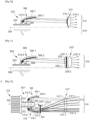
- THE figures 1 to 4 illustrate a first embodiment of a light device according to the invention.
- the light device 2 essentially comprises a first light source 4, a first collector 6 capable of reflecting the light rays emitted by the first light source to form a first light beam 12 along an optical axis 8 of the device, and a projection lens 10 of said beam. Projection optical systems other than the projection lens can be envisaged, such as in particular one or more mirrors.
- the light device 2 further comprises a second light source 14 opposite, with respect to the optical axis 8, to the first light source 4 and a second collector 16 also opposite to the first collector 6 and able to reflect the light rays emitted by the second light source 14 to form a second light beam 18 along the optical axis 8 of the device.
- the light sources 4 and 14 are advantageously of the semiconductor type, such as in particular an electroluminescence diode.
- Each of the light sources 4 and 14 emits light rays in a half-space delimited by the main plane of said source, according to the example shown, in a main direction perpendicular to said plane and to the optical axis 8.
- the main direction of emission may be inclined relative to a direction perpendicular to the optical axis by an angle less than or equal to 25°.
- Each of the collectors 6 and 16 comprises a support 6.1 and 16.1, in the form of a shell or cap, and a reflecting surface 6.2 and 16.2 on the inner face of the support 6.1 and 16.1.
- the reflective surfaces 6.2 and 16.2 advantageously have a profile of the elliptical or parabolic type. At least one of them is advantageously a surface of revolution around an axis parallel to the optical axis. Alternatively, it may be a free-form surface or a swept surface or an asymmetrical surface. It can also include several sectors.
- the collectors 6 and 16 in the form of a shell or cap are advantageously made of materials having good resistance to heat, for example glass or synthetic polymers such as polycarbonate PC or polyetherimide PEI.
- parabolic type generally applies to reflectors whose surface has a single focal point, that is to say a zone of convergence of the light rays such that the light rays emitted by a light source placed at the level of this convergence zone are projected at a great distance after reflection on the surface. Projected at a great distance means that these light rays do not converge on an area located at least 10 times the dimensions of the reflector. In other words, the reflected rays do not converge towards a convergence zone or, if they do converge, this convergence zone is located at a distance greater than or equal to 10 times the dimensions of the reflector.
- a parabolic-type surface may therefore have parabolic portions or not.
- a reflector having such a surface is generally used alone to create a light beam. Alternatively it can be used as a projection surface associated with an elliptical-type reflector. In this case, the light source of the parabolic-type reflector is the zone of convergence of the rays reflected by the elliptical-type reflector.
- Each of the light sources 4 and 14 is placed at a focal point of the corresponding reflecting surface 6.2 and 16.2 so that its rays are collected and reflected along the optical axis 8. At least some of these reflected rays have angles d inclination ⁇ , in a vertical plane, relative to said axis which are less than or equal to 25°, preferably less than or equal to 10°, so as to be under the so-called Gaussian conditions, making it possible to obtain a stigma, c ie sharpness of the projected image. These are advantageously the rays reflected by the rear part of the reflecting surface 6.2 and 16.2.
- the projection lens 10 has a first entry face 10.1 for the light rays corresponding to the first light beam 12, a second entry face 10.2 for the light rays corresponding to the second light beam 18, a first exit face 10.3 for the first light beam 12 and a second output face 10.4 of the second light beam 18.
- the first and second output faces 10.3 and 10.4 advantageously form an output face common to the two input faces 10.1 and 10.2.
- the lens 10 is said to be thin, for example with a thickness, along the optical axis of the device, which is less than 7 mm, in particular because of the low height of the lens and its long focal length.
- Lens 10 has a first focus 10.5 and a second focus 10.6, the first focus 10.5 corresponding to the upper part of the lens 10 and the second focus 10.6 corresponds to the lower part of the lens 10.
- Each of the first and second focuses 10.5 and 10.6 in question is located on a 6.3/16.3 zone located between the reflective surface 6.2/16.2 of the corresponding first or second collector 6/16 and the corresponding first or second light source 4/14 (these zones are delimited by the broken lines).
- at least one of the homes is located on the reflective surface 6.2/16.2 of the corresponding first or second collector 6/16.
- this focus it is also possible for this focus to be located at the rear or at the front of the reflection surface 6.2/16.2 provided that it is close, preferably less than 10 mm, preferably less 5mm.
- the reflective surface if it is of the elliptical type, has a second focus located in front of the lens 10 and at a distance from the optical axis 8. It should be noted that it is also possible for this focus to be located at behind the lens and/or on the optical axis, provided it is close to the lens, so as to reduce the width of the beam at the entrance face of the lens.
- first light source 4 and the first collector 6, on the one hand, and the second light source 14 and the second collector 16, on the other hand, are opposite with respect to the optical axis 8.
- first light source 4 is placed on a first plate 20 and the second light source 14 is placed on a second plate 22 distinct and distant from the first plate 20.
- a heat sink 24 is thermally coupled to the first and second light sources 4 and 16 via a portion 24.1 serving as a support for the first and second plates 20 and 22.
- the heat sink 24 also comprises a dissipating part 24.2 with cooling fins. This arrangement is particularly interesting from a thermal point of view. It is however understood that it is also possible for the first and second light sources to be arranged on opposite faces of a common plate.
- the luminous device advantageously comprises an absorbing screen 26 extending along the optical axis 8 which is located between the first and second collectors 6 and 16 and the lens 10, so as to absorb any light rays that encounter it and thus avoid parasitic reflections.
- the first light beam 12 is advantageously an illumination beam with upper horizontal cut-off (that is to say of the "dip” or “low-beam” type) and the second light beam 18 is advantageously an illumination beam without cutting (that is to say, in combination with the first light beam 12, of the “road” or “high-beam” type).
- FIG 2 is a rear view, in perspective, of one of the first and second collectors 6 and 16 of the light device 2 of the figure 1 , however oriented as the first manifold.
- the shell shape or cap of the support 6.1/16.1 as well as the fact that the reflecting surface (not visible) has a front edge 6.2.1/16.2.1 and a rear edge 6.2.2/16.2.2.
- the plane in question includes the rear edge 6.2.2/16.2 .2. This extends laterally in the plane on either side of the axis of revolution.
- FIG. 3 is a representation of the light intensity at the reflective surface 6.2 of the first collector seen from the outside, along the optical axis. More specifically, surface illuminance, ie the power of striking electromagnetic radiation per unit area perpendicular to its direction, expressed in W/m 2 .
- the dark zone covering the majority of the surface corresponds to weaker illuminations while the central, lighter zone corresponds to greater illuminations. It can be observed that the dark zone is clearly delimited by the edges 6.2.1 and 6.2.2.
- the illuminated surface 6.2 naturally has sharp edges capable of forming cuts in the projected lighting beam imaging this surface.
- the same reasoning applies to the second collector except that the light intensity distribution is rotated 180° around the optical axis.
- FIG 4 is a graphic representation of the images projected by the light device of the figure 1 .
- the horizontal axis H and the vertical axis V intersect at the level of the optical axis of the light device.
- the curves in solid line correspond to the first light beam 12 and the curves in broken line correspond to the second light beam 18.
- These curves are isolux, that is to say correspond to the zones of the light beam which have the same illumination expressed in lux.
- the curves in the center correspond to a higher level of illumination than at the periphery.
- the first light beam 12 has an upper horizontal cutoff, essentially at the level of the horizontal axis H.
- the cutoff is not perfectly straight; it has a curvature which corresponds to aberrations of the image thus produced.
- the horizontal cut is made by the edge 6.2.2 ( picture 3 ) which is the trailing edge ( picture 2 ) of the reflecting surface 6.2 of the first collector 6.
- the first focal point 10.5 of the lens 10 ( figure 1 ) is located close to this edge 6.2.2 ( picture 3 ), that is to say at the rear of the first light source 4.
- the light beam produced has, under the horizontal axis, a sharp contour corresponding to the front edge 6.2.1.
- the second light beam 18 essentially corresponds to a reversal of the first light beam 12 and concentrates light at the level of the horizontal axis H and above said axis so as to fully complete the first light beam 12.
- This concentration of light in the upper part of the second beam is produced by the part of the reflecting surface 16.2 which is close to the rear edge 16.2.2.
- the second focal point 10.6 of the lens 10 ( figure 1 ) is located close to the trailing edge 16.2.2 ( picture 2 ).
- FIG. 5 is a schematic representation of a variant of the light device outside the scope of the invention.
- This variant differs from the figure 1 in that the lens 10' no longer has a common exit face but rather separate exit faces.
- the second input face 10'.2 and the second output face 10'.4 are offset axially with respect to the first input faces 10'.1 and the output face 10'.3 . More particularly this offset is such that the second input 10'.2 and output 10'.4 faces are farther from the first and second collectors 6 and 16 than the first input 10'.1 and output 10' faces .3. This makes it possible in particular to respond to bulk constraints.
- FIG. 6 is a schematic view of a light device according to a second embodiment of the invention.
- the reference numbers of the first embodiment are used to designate identical or corresponding elements, these numbers however being increased by 100. Reference is also made to the description of these elements within the framework of the first embodiment. Specific numbers between 100 and 200 are used to designate elements specific to this embodiment.
- the second light source 114 and the second collector 116 are no longer opposed, with respect to the optical axis of the device, to the first light source 104 and to the first collector 106 but are located beside them. This.
- the first light source 104 and the first collector 106 are not visible because they are located behind the second light source 114 and the second collector 116.
- the light device 102 also comprises a mirror 126 arranged in the extension of the reflecting surface 116.2 of the collector 116.
- Mirror 126 includes a support 126.1 and a planar reflective surface 126.2 formed on support 126.1. The latter can be coincident with or adjacent to the support 116.1 of the collector 116.
- the light source 114 is arranged at a focal point of the reflecting surface 116.2 of the collector 116 so that its rays are collected and reflected towards the mirror 126.
- the latter reflects towards the projection lens 110 a virtual image 116.2 of the reflective surface 116.2, a virtual image 116 of the second collector 116 and a virtual image 114 of the light source 114, shown in broken lines at figure 6 .
- At least some of these rays reflected by mirror 126 have angles of inclination ⁇ , in a vertical plane and relative to said axis, which are less than or equal to 25°, preferably less than or equal to 10°, so as to be in the so-called Gaussian conditions, making it possible to obtain stigmatism, that is to say sharpness of the projected image.
- ⁇ angles of inclination ⁇ , in a vertical plane and relative to said axis, which are less than or equal to 25°, preferably less than or equal to 10°, so as to be in the so-called Gaussian conditions, making it possible to obtain stigmatism, that is to say sharpness of the projected image.
- the lens 110 then has two distinct parts for the first and second beams 112 and 118, these two parts being side by side and no longer on either side of the optical axis as in the first embodiment.
- the lens 110 then has a first input face 110.1 and a first output face 110.3 to form the first beam 112 and a second input face 110.2 and a second output face 110.4 to form the second beam 118. It is however note that the two output faces 110.3 and 110.4 can form a common output face as in the figure 1 or alternatively separate and potentially axially offset exit faces as at the figure 5 .
- the second part of the lens namely that with the second input and output faces 110.2 and 110.4, is advantageously of the biconvex type symmetrical with respect to the virtual optical axis 108 (in broken line) located above the optical axis 108.
- This part of the lens has a focus 110.6 located on this virtual axis and close to a rear edge of the reflecting surface of the virtual collector. This allows this portion of lens 110 to image the illuminated surface of second collector 116 similar to the first embodiment of the invention.
- FIG 7 is a schematic representation of a variant of the light device 102 of the second embodiment of the invention, illustrated in figure 6 .
- the luminous device 102' according to this variant differs from the figure 6 in that it is no longer the second light source 114 and the second collector 116 which are returned around the optical axis 108 but rather the first light source 104 and the first collector 106.
- the light source 104 is arranged at a focal point of the reflecting surface 106.2 of the first collector 106 so that its rays are collected and reflected towards the mirror 126. The latter reflects towards the projection lens 110 a virtual image 106.2 of the reflecting surface 106.2 of the first collector 106 and a virtual image 104 of the light source 104, shown in broken line at the figure 6 .
- this inversion makes it possible to obtain two opposite light beams (12 & 18) from light sources which have the same orientation.
- the first light source 104 and the first collector 106 can thus, despite the reversal, produce a light beam similar to the first light beam 12 of the first embodiment, illustrated in figure 4 , that is to say with a concentration of light at its upper part, in this case at the level of the horizontal axis.
- the first input and output faces 110'.1 and 110'.3 of the lens 110' are visible, the second input and output faces 110'.3 and 110'.4 not being visible.
- the first part of the lens 110' is then, similar to the second part of the lens of the figure 6 , advantageously of the symmetrical biconvex type with respect to the virtual optical axis 108 (in dashed line) located below the optical axis 108.
- This part of the lens has a focal point 110′.5 located on this virtual axis 108 and at proximity to a rear edge of the reflective surface 106.2 of the virtual collector.
- FIG 8 is a schematic view of a light device are a third embodiment of the invention.
- the reference numbers of the first and second embodiments are used to designate the identical or corresponding elements, these numbers being however increased by 200 and 100, respectively. Reference is also made to the description of these elements in the context of the first and second embodiments. Specific numbers between 200 and 300 are used to designate elements specific to this embodiment.
- This third embodiment has a similarity with the second mode ( figure 6 ) in that in this light device 202, the second light source 214 and the second collector 216 are no longer opposed, with respect to the optical axis of the device, to the first light source 204 and to the first collector 206 but rather located at side of these.
- the first light source 204 and the first collector 206 are not visible because they are located behind the second light source 214 and the second collector 216.
- the device 202 comprises a mirror 226 provided with a support 226.1 and an advantageously flat reflective surface 226.2 .
- the mirror 226 and more particularly the reflecting surface 226.2 extend along the optical axis 208.
- the reflective surface 216.2 of the second collector 216 is configured to reflect the rays emitted by the second light source 214 towards the reflective surface 226.2. The latter then reflects these rays in the form of a virtual image 214 of the second light source 214 and a virtual image 216.2 of the reflecting surface 216.2 of the second collector 216, these virtual images (in broken line) being located under the optical axis 208.
- the device 202 will produce an inverted light image of the illuminated surface of the second collector 216, corresponding to the virtual image 216 of the collector 216 (shown in dashed line) and located mainly above of the horizontal axis while having a concentration of light in the lower part, at the level of said axis.
- the lens 210 then has two separate parts for the first and second beams 212 and 218, these two parts being side by side and no longer on either side of the optical axis as in the first embodiment.
- the lens 210 then has a first input face 210.1 and a first output face 210.3 to form the first beam 212 and a second input face 210.2 and a second output face 210.4 to form the second beam 218. It is however note that the two output faces 210.3 and 210.4 can form a common output face as in the figure 1 or alternatively separate and potentially axially offset exit faces as at the figure 5 .
- the second part of the lens namely that with the second input and output faces 210.2 and 210.4, is advantageously of the biconvex type symmetrical with respect to the virtual optical axis (in broken line) located under the optical axis 208.
- This part of the lens has a focal point 210.6 situated on this virtual axis 208 and close to a rear edge of the reflecting surface of the virtual collector. This allows this portion of lens 210 to image the illuminated surface of second collector 216 similar to the first embodiment of the invention.
- FIG 9 is a schematic representation of a variant of the light device 202 of the third embodiment of the invention, illustrated in figure 8 .
- the luminous device 202' according to this variant differs from the figure 8 in that it is no longer the second light source 214 and the second collector 216 which are turned around the optical axis 208 but rather the first light source 204 and the first collector 206.
- the reflecting surface 206.2 of the first reflector is configured to reflect the light rays emitted by the first light source 204 towards the advantageously planar reflecting surface 226.2 of the reflecting screen 226.
- This reflecting surface 206.2 then reflects the rays light towards the lens 210', more exactly towards the first part of the lens 210', corresponding to the first input 210'.1 and output 210'.3 faces, thus causing an inversion of the light image, as if it was produced by virtual collector 206 and virtual light source 204 shown in dashed lines.
- this inversion makes it possible to cancel the inversion caused by the downward reversal of the first light source 204 and of the first collector 206.
- These can thus, despite the reversal, produce a light beam similar to the first light beam 12 of the first embodiment, illustrated in figure 4 , that is to say with a concentration of light at its upper part, in this case at the level of the horizontal axis.
- the first input 210'.1 and output 210'.3 faces of the lens 210' are visible, the second input 210'.3 and output 210'.4 faces not being visible.
- the first part of the lens 210' is then, similar to the second part of the lens of the figure 8 , advantageously of the symmetrical biconvex type with respect to the virtual optical axis 208 (in dashed line) located above the optical axis 208.
- This part of the lens has a focus 210′.5 located on this virtual axis and close of a rear edge of the reflective surface of the virtual collector.
- FIG 10 is a schematic view of a light device are a fourth embodiment of the invention.
- the reference numbers of the first embodiment are used to designate identical or corresponding elements, these numbers being however increased by 300. Reference is also made to the description of these elements within the framework of the first embodiment. Specific numbers between 300 and 400 are used to designate elements specific to this embodiment.
- the luminous device 302 of the figure 10 differs from the luminous device of the first embodiment at the figure 1 , essentially in that one of the bundles light is a light signaling beam.
- the first and second light beams 12 and 18 are indeed advantageously lighting beams, in this case with horizontal cutoff (“code” or “low beam” function) and without cutoff ( complementary function "route” or "high-beam” in English).
- the first light beam 312 is a light signaling beam.
- graining is provided on the first input face 310.1 of the lens.
- the second light source, the second collector and the second part of the lens are similar to one of the first, second and third embodiments. It is thus understood that the second light beam can be with or without cut-off and that the second light source and the second collector can be located above or below the optical axis 308.
- FIG 11 illustrates a first variant of the fourth embodiment of the figure 10 .
- the luminous device 302' according to this variant has graining which, instead of being on the corresponding input face of the lens, is located on at least one of the input 328.1 and output 328.2 faces of an intermediate lens 328 located optically between the first collector 306 and the main lens 310.
- the light rays reflected by the reflecting surface 306.1 of the first collector 306 pass through the intermediate lens before reaching the main lens 310. They are advantageously diffused through the diopter formed by the grained exit face 328.2 of the intermediate lens.
- FIG 12 illustrates a second variant of the fourth embodiment of the figure 10 .
- the light device 302" according to this variant is illustrated completely, that is to say with, on one side of the optical axis 308, in this case above, the first light source 304 and the first collector 306, and on another side of the optical axis, in this case below, the second light source 314 and the second collector 316.
- an intermediate lens 328 is provided. In this case it is placed optically between the second collector 316 and the main lens 310".
- the intermediate lens 328 is placed close to the second collector 316, in any case at a distance from the main lens 310" so as to diffuse the second light beam not only towards the second input face 310".3 of the lens 310 but also towards the first input face 310 ".1.
- the second diffusing light beam 318 thus superimposes the first beam 312, in this case lighting and preferably with horizontal cutoff.
- the number of light sources and corresponding collectors is not limited to two. It is in fact conceivable to provide more light sources and corresponding collectors.
- the different light produced by the different pairs of light source and collector can be juxtaposed and/or superimposed.
- the second beam produced by the light source and the collector located below the optical axis, said beam being in this case diffusing is superimposed, at least in part, on the first light beam.
- each of the first, second light sources and possibly additional light sources can consist of several light zones that can be activated in a discretionary manner and emit light rays towards the corresponding collector.
- the light sources on the one hand and the associated collectors on the other hand can be arranged side by side.
- part of the light sources and their associated collector can be opposed to the other part of the light sources and their associated collector, with respect to the optical axis.
- the lighting device in its functional position, can thus comprise a collector participating in the formation of a lighting beam with horizontal cutoff, a collector participating in the formation of a beam with a jump cutoff and a collector participating to the formation of a light beam forming part of a high beam function arranged side by side.
- a first and a second light source respectively associated with a first and a second collector opposite with respect to the optical axis to a third light source and to the third collector with which the third source is associated.
- the light device in its functional position, may comprise a first collector and a second collector participating respectively in the formation of a lighting beam with horizontal cutoff and of a beam with a jump cutoff above the optical axis, and a third collector participating in the formation of a light beam forming part of the driving light function below the optical axis.
- the light device in its functional position, may comprise a first collector and a second collector participating respectively in the formation of a lighting function and a signaling function above the optical axis and a third collector participating in the formation of a light beam forming all or part of a signaling function below the optical axis.
- first light source associated with a first collector, opposite with respect to the optical axis to a second light source and to the second collector with which the second source is associated.
- the lighting device in its functional position, can thus comprise a first collector participating in the formation of an uninterrupted lighting beam forming a first lighting function above the optical axis, and a second collector participating in the formation of a signal beam below the optical axis.
Landscapes
- Engineering & Computer Science (AREA)
- General Engineering & Computer Science (AREA)
- Physics & Mathematics (AREA)
- Microelectronics & Electronic Packaging (AREA)
- Optics & Photonics (AREA)
- Mechanical Engineering (AREA)
- Non-Portable Lighting Devices Or Systems Thereof (AREA)
- Lenses (AREA)
- Lighting Device Outwards From Vehicle And Optical Signal (AREA)
- Measurement Of Optical Distance (AREA)
Claims (16)
- Leuchtvorrichtung (2; 302, 302', 302"), insbesondere für ein Kraftfahrzeug, die Folgendes beinhaltet:- eine erste Lichtquelle (4; 304) und eine zweite Lichtquelle (14; 314), die jeweils dazu fähig sind, Lichtstrahlen zu emittieren;- einen ersten Kollektor (6; 306) und einen zweiten Kollektor (16; 316) mit jeweils einer konkaven reflektierenden Oberfläche (6.2, 16.2; 306.2, 316.2), die dazu konfiguriert ist, die durch die erste (4; 304) bzw. die zweite (14; 314) Lichtquelle emittierten Lichtstrahlen zu sammeln und zu reflektieren;- ein optisches System (10, 10'; 310, 310', 310"), das dazu konfiguriert ist, die durch die reflektierenden Oberflächen (6.2, 16.2; 306.2, 316.2) des ersten (6; 306) und des zweiten (16; 316) Kollektors reflektierten Lichtstrahlen in einem ersten Lichtbündel (12; 312) bzw. in einem zweiten Lichtbündel (18; 318) gemäß einer optischen Achse der Vorrichtung (8; 308) zu projizieren; wobei das optische System (10, 10'; 310, 310', 310") dazu konfiguriert ist, ein Lichtbild der reflektierenden Oberfläche (6.2, 16.2; 306.2, 316.2) von jedem von dem ersten (6; 306) und dem zweiten (16; 316) Kollektor zu bilden, wobei die reflektierenden Oberflächen (6.2, 16.2; 306.2, 316.2) in Bezug auf eine allgemeine Ausbreitungsrichtung des entsprechenden Lichtbündels einen vorderen Rand (6.2.1; 16.2.1) und einen hinteren Rand (6.2.2; 16.2.2) aufweisen, wobei die Ränder das entsprechende Lichtbild in entgegengesetzten Richtungen begrenzen, und wobei jedes von dem ersten (12; 312) und dem zweiten (18; 318) Lichtbündel einen Teil oder die Gesamtheit einer Beleuchtungs- oder Signalisierungsfunktion bildet, die sich von der Beleuchtungs- oder Signalisierungsfunktion des anderen von dem ersten und dem zweiten Bündel unterscheidet, dadurch gekennzeichnet, dass:- das optische System (10, 10'; 310, 310', 310") einen ersten Brennpunkt (10.5; 310.5), der sich axial hinter einer vorderen Grenze der reflektierenden Oberfläche (6.2; 306.2) des ersten Kollektors (6; 306) befindet, und einen zweiten Brennpunkt (10.6; 310.6), der sich axial hinter einer vorderen Grenze der reflektierenden Oberfläche (16.2; 316.2) des zweiten Kollektors (16; 316) befindet, aufweist; und- sich der erste Brennpunkt (10.5; 310.5) des optischen Systems in der Nähe des hinteren Randes (6.2.2) der reflektierenden Oberfläche (6.2; 306.2) des ersten Kollektors (6; 306) befindet und sich der zweite Brennpunkt (10.6; 310.6) des optischen Systems in der Nähe des hinteren Randes (16.2.2) der reflektierenden Oberfläche (16.2; 316.2) des zweiten Kollektors (16; 316) befindet.
- Leuchtvorrichtung (102, 102'; 202, 202'), insbesondere für ein Kraftfahrzeug, die Folgendes beinhaltet:- eine erste Lichtquelle (104; 204) und eine zweite Lichtquelle (114; 214), die jeweils dazu fähig sind, Lichtstrahlen zu emittieren;- einen ersten Kollektor (106; 206) und einen zweiten Kollektor (116; 216) mit jeweils einer konkaven reflektierenden Oberfläche (106.2, 116.2; 206.2, 216.2), die dazu konfiguriert ist, die durch die erste (104; 204) bzw. die zweite (114; 214) Lichtquelle emittierten Lichtstrahlen zu sammeln und zu reflektieren;- ein optisches System (110, 110'; 210, 210'), das dazu konfiguriert ist, die durch die reflektierenden Oberflächen (106.2, 116.2; 206.2, 216.2) des ersten (106; 206)und des zweiten (116; 216) Kollektors reflektierten Lichtstrahlen in einem ersten Lichtbündel (112; 212) bzw. in einem zweiten Lichtbündel (118; 218) gemäß einer optischen Achse der Vorrichtung (108; 208) zu projizieren;wobei das optische System (110, 110'; 210, 210') dazu konfiguriert ist, ein Lichtbild der reflektierenden Oberfläche (106.2, 116.2; 206.2, 216.2) von jedem von dem ersten (106; 206) und dem zweiten (116; 216) Kollektor zu bilden, wobei die reflektierenden Oberflächen (106.2, 116.2; 206.2, 216.2) in Bezug auf eine allgemeine Ausbreitungsrichtung des entsprechenden Lichtbündels einen vorderen Rand und einen hinteren Rand aufweisen, wobei die Ränder das entsprechende Lichtbild in entgegengesetzten Richtungen begrenzen, und wobei jedes von dem ersten (112; 212) und dem zweiten (118; 218) Lichtbündel einen Teil oder die Gesamtheit einer Beleuchtungs- oder Signalisierungsfunktion bildet, die sich von der Beleuchtungs- oder Signalisierungsfunktion des anderen von dem ersten und dem zweiten Bündel unterscheidet,dadurch gekennzeichnet, dass:- das optische System (110, 110'; 210, 210') einen ersten Brennpunkt (110.5; 210.5), der sich axial hinter einer vorderen Grenze der reflektierenden Oberfläche (106.2; 206.2) des ersten Kollektors (106; 206) befindet, und einen zweiten Brennpunkt (110.6; 210.6), der sich axial hinter einer vorderen Grenze der reflektierenden Oberfläche (116.2; 216.2) des zweiten Kollektors (116; 216) befindet, aufweist; und- die Leuchtvorrichtung ferner einen Spiegel (126; 226) beinhaltet, wobei die reflektierende Oberfläche (106.2; 206.2) des ersten Kollektors (106; 206) dazu konfiguriert ist, die durch die erste Lichtquelle (104; 204) emittierten Lichtstrahlen zu sammeln und zu dem Spiegel (126; 226) zu reflektieren, bzw. die reflektierende Oberfläche (116.2; 216.2) des zweiten Kollektors (116; 216) dazu konfiguriert ist, die durch die zweite Lichtquelle (114; 214) emittierten Lichtstrahlen zu sammeln und zu dem Spiegel (126; 216) zu reflektieren, und wobei der Spiegel (126; 216) dazu konfiguriert ist, ein virtuelles Bild (104, 114, 106.2, 116.2; 204, 214, 206.2, 216.2) der ersten Lichtquelle (104; 204) und der reflektierenden Oberfläche des ersten Kollektors (106; 206) bzw. der zweiten Lichtquelle (114; 214) und der reflektierenden Oberfläche des zweiten Kollektors (116; 216) zu bilden, wobei das optische System (110, 110'; 210, 210') ein Bild des virtuellen Bildes (104, 114, 106.2, 116.2; 204, 214, 206.2, 216.2) bildet, und- sich der erste Brennpunkt (110'.5; 210.5, 210'.5) des optischen Systems in der Nähe des hinteren Randes des virtuellen Bildes der reflektierenden Oberfläche (106.2; 206.2) des ersten Kollektors (106; 206) befindet und sich der zweite Brennpunkt (110.6; 210.6) des optischen Systems in der Nähe des hinteren Randes der reflektierenden Oberfläche (116.2; 216.2) des zweiten Kollektors (116; 216) befindet bzw. sich der erste Brennpunkt (110'.5; 210.5, 210'.5) des optischen Systems in der Nähe des hinteren Randes der reflektierenden Oberfläche (106.2; 206.2) des ersten Kollektors (106; 206) befindet und sich der zweite Brennpunkt (110.6; 210.6) des optischen Systems in der Nähe des hinteren Randes des virtuellen Bildes der reflektierenden Oberfläche (116.2; 216.2) des zweiten Kollektors (116; 216) befindet.
- Leuchtvorrichtung (102, 102'; 202, 202') nach Anspruch 2, dadurch gekennzeichnet, dass sich der Spiegel (126) in der Verlängerung der reflektierenden Oberfläche des entsprechenden Kollektors (106, 116) erstreckt oder sich der Spiegel (226) entlang der optischen Achse (208) erstreckt.
- Leuchtvorrichtung (102'; 202') nach einem der Ansprüche 2 und 3, dadurch gekennzeichnet, dass sich der erste Kollektor (106; 206) und die erste Lichtquelle (104; 204) unterhalb der optischen Achse (108; 208) befinden, wenn die Vorrichtung gemäß der Betriebsstellung ausgerichtet ist, wobei das erste Bündel (112; 212) ein Beleuchtungsbündel mit einer oberen horizontalen Hell-Dunkel-Grenze ist, die durch den hinteren Rand der reflektierenden Oberfläche (106.2; 206.2) des ersten Kollektors (106; 206) realisiert wird.
- Leuchtvorrichtung (102; 202) nach einem der Ansprüche 2 und 3, dadurch gekennzeichnet, dass sich der zweite Kollektor (116; 216) und die zweite Lichtquelle (114; 214) oberhalb der optischen Achse (108; 208) befinden, wenn die Vorrichtung gemäß der Betriebsstellung ausgerichtet ist, wobei das zweite Bündel (118; 218) ein Beleuchtungsbündel mit einem oberen Teil ohne horizontale Hell-Dunkel-Grenze ist, der durch einen vorderen Teil der reflektierenden Oberfläche (116.2; 216.2) des zweiten Kollektors (116; 216) gebildet wird.
- Leuchtvorrichtung (2; 102, 102'; 202, 202'; 302, 302', 302") nach einem der Ansprüche 1 bis 5, dadurch gekennzeichnet, dass mindestens einer von dem ersten (6; 106; 206; 306) und dem zweiten (16; 116; 216; 316) Kollektor dazu konfiguriert ist, dass die durch einen hinteren Teil der reflektierenden Oberfläche (6.2, 16.2; 106.2, 116.2; 206.2, 216.2; 306.2, 316.2) des Kollektors reflektierten Lichtstrahlen parallel zu der optischen Achse (8; 108; 208; 308) sind oder in einer vertikalen Ebene und mit Bezug auf die Achse einen Neigungswinkel kleiner als oder gleich 25°, vorzugsweise kleiner als oder gleich 10°, aufweisen.
- Leuchtvorrichtung (2; 102, 102'; 202, 202'; 302, 302', 302") nach einem der Ansprüche 1 bis 6, dadurch gekennzeichnet, dass die erste (4; 104; 204; 304) und die zweite (14; 114; 214; 314) Lichtquelle dazu konfiguriert sind, in einer zu der optischen Achse (8; 108; 208; 308) senkrechten oder in Bezug auf eine zu der optischen Achse senkrechte Richtung um weniger als oder gleich 25° geneigten Hauptrichtung zu emittieren, und die reflektierenden Oberflächen (6.2, 16.2; 106.2, 116.2; 206.2, 216.2; 306.2, 316.2) des ersten (6; 106; 206; 306) und des zweiten (16; 116; 216; 316) Kollektors ein elliptisches oder parabolisches Profil aufweisen.
- Leuchtvorrichtung (2; 102, 102'; 202, 202'; 302, 302', 302") nach einem der Ansprüche 1 bis 7, dadurch gekennzeichnet, dass das optische System eine Linse (10; 110, 110'; 210, 201'; 310, 310', 310") mit einer ersten Eintrittsfläche (10.1; 110.1, 110'.1; 210.1, 210'.1; 310.1, 310'.1, 310".1) für die Lichtstrahlen des ersten Lichtbündels (12; 112; 212; 312) und einer zweiten Eintrittsfläche (10.2; 110.2, 110'.2; 210.2, 210'.2; 310.2, 310".2) für die Lichtstrahlen des zweiten Lichtbündels (18; 118; 218; 318) ist.
- Leuchtvorrichtung (2; 102, 102'; 202, 202'; 302, 302', 302") nach Anspruch 8, dadurch gekennzeichnet, dass die erste und die zweite Eintrittsfläche (10.1, 10.2; 110.1, 110.2, 110'.1, 110'.2; 210.1, 210.2, 210'.1, 210'.2; 310.1, 310.2, 310'.1, 310'.2, 310".1, 310".2) senkrecht zu der optischen Achse (8; 108; 208; 308) ausgerichtet sind.
- Leuchtvorrichtung (2; 102; 202; 302") nach einem der Ansprüche 8 und 9, dadurch gekennzeichnet, dass die Linse (10; 110; 210; 310") eine Austrittsfläche (10.3, 10.4; 110.3, 110.4; 210.3, 210.4; 310".3, 310".4) aufweist, die der ersten und zweiten Eintrittsfläche (10.1, 10.2; 110.1, 110.2; 210.1, 210.2; 310".1, 310".2) gemein ist.
- Leuchtvorrichtung (2; 102, 102'; 202, 202'; 302") nach einem der Ansprüche 1 bis 10, dadurch gekennzeichnet, dass der erste Kollektor (6; 306) und die erste Lichtquelle (4; 304) in Bezug auf die optische Achse (8; 308) jeweils zu dem zweiten Kollektor (16; 316) und der zweiten Lichtquelle (14; 314) entgegengesetzt sind; oder der erste Kollektor (106; 206) und die erste Lichtquelle (104; 204) einerseits und der zweite Kollektor (116; 216) und die zweite Lichtquelle (114; 214) andererseits nebeneinander angeordnet sind.
- Leuchtvorrichtung (2; 102; 202; 302") nach Anspruch 1, dadurch gekennzeichnet, dass sich der erste Kollektor (6; 106; 206; 306) und die erste Lichtquelle (4; 104; 204; 304) oberhalb der optischen Achse (8; 108; 208; 308) befinden, wenn die Vorrichtung gemäß der Betriebsstellung ausgerichtet ist, wobei das erste Bündel (12; 112; 212; 312) ein Beleuchtungsbündel mit einer oberen horizontalen Hell-Dunkel-Grenze ist, die durch den hinteren Rand (6.2.2) der reflektierenden Oberfläche (6.2; 106.2; 206.2; 306.2) des ersten Kollektors (6; 106; 206; 306) realisiert wird.
- Leuchtvorrichtung (302") nach einem der Ansprüche 1 bis 12, dadurch gekennzeichnet, dass das erste Lichtbündel (312) ein Beleuchtungsbündel mit oder ohne obere horizontale Hell-Dunkel-Grenze ist und das zweite Bündel (318) ein Signalisierungsbündel ist, wobei das optische System (310) ein gekörntes Diopter (328.2) beinhaltet, das dazu konfiguriert ist, das zweite Lichtbündel (318) zu streuen.
- Leuchtvorrichtung (302") nach einem der Ansprüche 8 bis 10 und nach Anspruch 13, dadurch gekennzeichnet, dass das gekörnte Diopter auf der zweiten Eintrittsfläche (310".2) gebildet ist.
- Leuchtvorrichtung (302") nach einem der Ansprüche 8 bis 10 und nach Anspruch 13, dadurch gekennzeichnet, dass die Linse (310) eine Hauptlinse ist, wobei das optische System eine Zwischenlinse (328) mit dem gekörnten Diopter (328.2) beinhaltet, die optisch zwischen der reflektierenden Oberfläche (316.2) des zweiten Kollektors (316) und der Hauptlinse (310) angeordnet ist.
- Leuchtvorrichtung (102, 102'; 202, 202') nach einem der Ansprüche 1 bis 15, dadurch gekennzeichnet, dass die erste (104; 204)und die zweite (114; 214) Lichtquelle auf einer gemeinsamen Platte angeordnet sind.
Priority Applications (2)
| Application Number | Priority Date | Filing Date | Title |
|---|---|---|---|
| RS20230852A RS64733B1 (sr) | 2019-03-14 | 2020-02-21 | Uređaj za osvetljenje za prikazivanje osvetljenih površina najmanje dva raspodeljivača |
| EP23174455.8A EP4235024B1 (de) | 2019-03-14 | 2020-02-21 | Leuchtvorrichtung, die die beleuchteten flächen von mindestens zwei kollektoren abbildet |
Applications Claiming Priority (1)
| Application Number | Priority Date | Filing Date | Title |
|---|---|---|---|
| FR1902618A FR3093789B1 (fr) | 2019-03-14 | 2019-03-14 | Dispositif lumineux imageant les surfaces eclairees d’au moins deux collecteurs |
Related Child Applications (2)
| Application Number | Title | Priority Date | Filing Date |
|---|---|---|---|
| EP23174455.8A Division EP4235024B1 (de) | 2019-03-14 | 2020-02-21 | Leuchtvorrichtung, die die beleuchteten flächen von mindestens zwei kollektoren abbildet |
| EP23174455.8A Division-Into EP4235024B1 (de) | 2019-03-14 | 2020-02-21 | Leuchtvorrichtung, die die beleuchteten flächen von mindestens zwei kollektoren abbildet |
Publications (2)
| Publication Number | Publication Date |
|---|---|
| EP3708904A1 EP3708904A1 (de) | 2020-09-16 |
| EP3708904B1 true EP3708904B1 (de) | 2023-06-28 |
Family
ID=68072505
Family Applications (2)
| Application Number | Title | Priority Date | Filing Date |
|---|---|---|---|
| EP23174455.8A Active EP4235024B1 (de) | 2019-03-14 | 2020-02-21 | Leuchtvorrichtung, die die beleuchteten flächen von mindestens zwei kollektoren abbildet |
| EP20158870.4A Active EP3708904B1 (de) | 2019-03-14 | 2020-02-21 | Leuchtvorrichtung, die die beleuchteten flächen von mindestens zwei kollektoren abbildet |
Family Applications Before (1)
| Application Number | Title | Priority Date | Filing Date |
|---|---|---|---|
| EP23174455.8A Active EP4235024B1 (de) | 2019-03-14 | 2020-02-21 | Leuchtvorrichtung, die die beleuchteten flächen von mindestens zwei kollektoren abbildet |
Country Status (8)
| Country | Link |
|---|---|
| US (1) | US11022266B2 (de) |
| EP (2) | EP4235024B1 (de) |
| JP (1) | JP7523924B2 (de) |
| KR (1) | KR102841260B1 (de) |
| CN (1) | CN111692567B (de) |
| FR (1) | FR3093789B1 (de) |
| PL (1) | PL3708904T3 (de) |
| RS (1) | RS64733B1 (de) |
Cited By (1)
| Publication number | Priority date | Publication date | Assignee | Title |
|---|---|---|---|---|
| WO2025168791A1 (fr) * | 2024-02-09 | 2025-08-14 | Valeo Vision | Module lumineux |
Families Citing this family (21)
| Publication number | Priority date | Publication date | Assignee | Title |
|---|---|---|---|---|
| FR3084728B1 (fr) | 2018-07-31 | 2021-03-19 | Valeo Vision | Module lumineux imageant la surface eclairee d'un collecteur |
| WO2022117431A2 (en) * | 2020-12-02 | 2022-06-09 | Ams-Osram Ag | Optical system for an automotive headlamp |
| FR3118125B1 (fr) * | 2020-12-17 | 2022-12-30 | Valeo Vision | Module lumineux imageant la surface eclairee d’un collecteur avec bloqueur de rayons parasites |
| FR3118124B1 (fr) | 2020-12-18 | 2022-12-30 | Valeo Vision | Module d’éclairage automobile bi-fonction avec eclairage de la lentille d’un module d’eclairage inactif |
| FR3118122B1 (fr) * | 2020-12-18 | 2023-02-24 | Valeo Vision | Module lumineux d’un dispositif d’éclairage de véhicule automobile |
| FR3118127B1 (fr) * | 2020-12-18 | 2022-12-16 | Valeo Vision | Dispositif lumineux bi-fonction avec lentille rotative |
| FR3119440B1 (fr) | 2021-01-29 | 2024-01-12 | Valeo Vision | Dispositif d’éclairage de la route d’un véhicule automobile |
| FR3123415A1 (fr) * | 2021-05-27 | 2022-12-02 | Valeo Vision | Module lumineux comprenant un élément absorbant la lumière |
| DE102021113978B4 (de) | 2021-05-31 | 2023-03-16 | HELLA GmbH & Co. KGaA | Beleuchtungsmodul und Beleuchtungsverfahren zum Erzeugen zweier unterschiedlicher Leuchtbilder |
| FR3126029B1 (fr) * | 2021-08-04 | 2023-08-11 | Valeo Vision | Module lumineux pour véhicule automobile et procédé d’assemblage d’un tel module lumineux |
| FR3126747B1 (fr) * | 2021-09-03 | 2023-11-17 | Valeo Vision | Dispositif lumineux d’un véhicule automobile |
| CN217131136U (zh) | 2021-09-23 | 2022-08-05 | 法雷奥照明湖北技术中心有限公司 | 一种照明装置和机动车辆 |
| FR3133901B1 (fr) * | 2022-03-28 | 2024-03-01 | Valeo Vision | Module lumineux imageant la surface éclairée d’un collecteur avec bloqueur de rayons parasites extrudé |
| JP2025528228A (ja) * | 2022-08-18 | 2025-08-26 | ヴァレオ ビジョン | 自動車両用の発光モジュール |
| FR3139375B1 (fr) | 2022-09-06 | 2024-10-04 | Valeo Vision | Module d’éclairage route avec source lumineuse dirigée vers le haut |
| FR3141988B1 (fr) | 2022-11-14 | 2024-10-18 | Valeo Vision | Module d’eclairage multifonction avec dispositif optique de projection à aspect éclairé |
| CN120444573A (zh) * | 2022-12-05 | 2025-08-08 | 华域视觉科技(上海)有限公司 | 一种近光出光模组及远近光照明装置和车灯 |
| FR3151380A1 (fr) * | 2023-07-21 | 2025-01-24 | Valeo Vision | Module lumineux d’un véhicule automobile |
| DE102023123851B3 (de) * | 2023-09-05 | 2024-10-24 | HELLA GmbH & Co. KGaA | Beleuchtungsvorrichtung für Fahrzeuge |
| CN120194279A (zh) * | 2023-12-22 | 2025-06-24 | 法雷奥照明公司 | 照明模块、车辆前照灯和车辆 |
| TWI882886B (zh) * | 2024-08-16 | 2025-05-01 | 巨鎧精密工業股份有限公司 | 車燈裝置 |
Citations (1)
| Publication number | Priority date | Publication date | Assignee | Title |
|---|---|---|---|---|
| EP2182272B1 (de) * | 2008-10-30 | 2013-11-20 | Koito Manufacturing Co., Ltd. | Fahrzeuglampeneinheit und Fahrzeuglampe |
Family Cites Families (22)
| Publication number | Priority date | Publication date | Assignee | Title |
|---|---|---|---|---|
| FR2839139B1 (fr) * | 2002-04-25 | 2005-01-14 | Valeo Vision | Module d'eclairage elliptique sans cache realisant un faisceau d'eclairage a coupure et projecteur comportant un tel module |
| FR2847655B1 (fr) * | 2002-11-21 | 2005-03-04 | Valeo Vision | Projecteur elliptique pour vehicule automobile emettant des faisceaux d'eclairage differents |
| FR2858042B1 (fr) * | 2003-07-24 | 2005-09-23 | Valeo Vision | Module d'eclairage elliptique sans cache realisant un faisceau d'eclairage a coupure et projecteur comportant un tel module |
| EP1762776B1 (de) * | 2005-09-09 | 2015-04-15 | Valeo Vision | Verfahren zur Herstellung eines Moduls eines Kraftfahrzeugscheinwerfers |
| JP4615417B2 (ja) * | 2005-10-13 | 2011-01-19 | 株式会社小糸製作所 | 車両用前照灯の灯具ユニット |
| JP2009184410A (ja) * | 2008-02-04 | 2009-08-20 | Koito Mfg Co Ltd | 車両用照明灯具 |
| EP2337991B2 (de) * | 2008-09-18 | 2018-03-07 | Philips Intellectual Property & Standards GmbH | Lampeneinheit und fahrzeugscheinwerfer |
| JP2010153270A (ja) * | 2008-12-26 | 2010-07-08 | Toyoda Gosei Co Ltd | 発光装置 |
| JP2011100583A (ja) * | 2009-11-04 | 2011-05-19 | Koito Mfg Co Ltd | 光学ユニット |
| JP5879065B2 (ja) * | 2011-07-29 | 2016-03-08 | スタンレー電気株式会社 | 車両用前照灯 |
| FR2979594B1 (fr) * | 2011-09-05 | 2013-09-13 | Valeo Vision | Projecteur pour vehicule automobile |
| FR2979688A1 (fr) * | 2011-09-05 | 2013-03-08 | Valeo Vision | Module optique pour dispositif de signalisation et/ou d'eclairage |
| JP6030932B2 (ja) * | 2012-11-26 | 2016-11-24 | 株式会社小糸製作所 | 車両用前照灯 |
| DE102014112937B4 (de) * | 2014-09-09 | 2018-05-24 | HELLA GmbH & Co. KGaA | Beleuchtungsvorrichtung für Fahrzeuge |
| KR101819000B1 (ko) * | 2015-05-12 | 2018-01-16 | 엘지전자 주식회사 | 차량용 조명 장치 및 이를 포함하는 차량 |
| JP6519353B2 (ja) * | 2015-06-29 | 2019-05-29 | 市光工業株式会社 | 車両用前照灯 |
| JP6627282B2 (ja) * | 2015-06-30 | 2020-01-08 | 市光工業株式会社 | 車両用前照灯 |
| FR3038695A1 (fr) * | 2015-07-10 | 2017-01-13 | Valeo Vision | Module lumineux pour l'eclairage et/ou la signalisation d'un vehicule automobile |
| FR3039630A1 (fr) * | 2015-07-28 | 2017-02-03 | Valeo Vision | Systeme d'eclairage pour projecteur de vehicule automobile |
| FR3047541B1 (fr) | 2015-12-10 | 2019-10-04 | Valeo Vision | Module d'eclairage automobile avec fonctions code et route combinees et une source lumineuse ajustable |
| FR3050011A1 (fr) * | 2016-04-11 | 2017-10-13 | Valeo Vision | Module d'emission d'un faisceau lumineux pour projecteur de vehicule automobile |
| FR3058105B1 (fr) * | 2016-10-28 | 2021-04-02 | Valeo Vision | Module optique pour projeter un faisceau lumineux a coupure comportant des moyens de focalisation horizontale |
-
2019
- 2019-03-14 FR FR1902618A patent/FR3093789B1/fr active Active
-
2020
- 2020-02-21 EP EP23174455.8A patent/EP4235024B1/de active Active
- 2020-02-21 EP EP20158870.4A patent/EP3708904B1/de active Active
- 2020-02-21 PL PL20158870.4T patent/PL3708904T3/pl unknown
- 2020-02-21 RS RS20230852A patent/RS64733B1/sr unknown
- 2020-03-12 KR KR1020200030808A patent/KR102841260B1/ko active Active
- 2020-03-13 CN CN202010175992.7A patent/CN111692567B/zh active Active
- 2020-03-13 JP JP2020044441A patent/JP7523924B2/ja active Active
- 2020-05-14 US US15/931,974 patent/US11022266B2/en active Active
Patent Citations (1)
| Publication number | Priority date | Publication date | Assignee | Title |
|---|---|---|---|---|
| EP2182272B1 (de) * | 2008-10-30 | 2013-11-20 | Koito Manufacturing Co., Ltd. | Fahrzeuglampeneinheit und Fahrzeuglampe |
Cited By (1)
| Publication number | Priority date | Publication date | Assignee | Title |
|---|---|---|---|---|
| WO2025168791A1 (fr) * | 2024-02-09 | 2025-08-14 | Valeo Vision | Module lumineux |
Also Published As
| Publication number | Publication date |
|---|---|
| KR102841260B1 (ko) | 2025-07-31 |
| EP4235024A3 (de) | 2023-09-13 |
| US20210010653A1 (en) | 2021-01-14 |
| PL3708904T3 (pl) | 2024-01-08 |
| JP7523924B2 (ja) | 2024-07-29 |
| EP3708904A1 (de) | 2020-09-16 |
| RS64733B1 (sr) | 2023-11-30 |
| KR20200110221A (ko) | 2020-09-23 |
| CN111692567A (zh) | 2020-09-22 |
| JP2020149975A (ja) | 2020-09-17 |
| FR3093789B1 (fr) | 2022-05-27 |
| CN111692567B (zh) | 2024-08-20 |
| US11022266B2 (en) | 2021-06-01 |
| EP4235024A2 (de) | 2023-08-30 |
| FR3093789A1 (fr) | 2020-09-18 |
| EP4235024B1 (de) | 2026-03-18 |
Similar Documents
| Publication | Publication Date | Title |
|---|---|---|
| EP3708904B1 (de) | Leuchtvorrichtung, die die beleuchteten flächen von mindestens zwei kollektoren abbildet | |
| WO2020025171A1 (fr) | Module lumineux imageant la surface eclairee d'un collecteur | |
| EP4264122B1 (de) | Beleuchtungsvorrichtung für ein kfz | |
| EP3167226B1 (de) | Beleuchtungsmodul für ein kraftfahrzeug | |
| EP4134586B1 (de) | Beleuchtungsvorrichtung zur abbildung einer virtuellen beleuchteten oberfläche eines kollektors | |
| EP4062098B1 (de) | Kombiniertes leuchtmodul zur abbildung der beleuchteten fläche eines kollektors | |
| FR3050011A1 (fr) | Module d'emission d'un faisceau lumineux pour projecteur de vehicule automobile | |
| EP1500869A1 (de) | Elliptische Beleuchtungseinheit ohne Lichtblende zur Erzeugung eines Abblendlichtbündels und Scheinwerfer mit einer derartigen Belleuchtungseinheit | |
| WO2022129625A1 (fr) | Projecteur automobile avec plusieurs modules d'éclairage sur une platine commune inclinée | |
| FR3077367A1 (fr) | Module lumineux bi-fonction avec surface eclairee commune | |
| EP2976569B1 (de) | Beleuchtungs- und/oder meldemodul für ein kraftfahrzeug | |
| WO2022129420A1 (fr) | Module lumineux imageant la surface eclairee d'un collecteur avec bloqueur de rayons parasites | |
| EP4264123B1 (de) | Beleuchtungsvorrichtung mit doppelfunktion und rotierender linse | |
| EP2302292A1 (de) | Optisches Modul mit Falzmaschine, das aus einem Diopter für transparentes Material/Luft gebildet wird | |
| EP4569262A1 (de) | Scheinwerfer mit vertikaler hell-dunkel-grenze und verlängerung für ein kraftfahrzeug | |
| EP4500074B1 (de) | Lichtmodul mit einer die beleuchtete fläche eines kollektors abbildenden linse und einem streuende direktstrahlen blockierenden schirm | |
| WO2025132840A1 (fr) | Unite lumineuse pour vehicule automobile | |
| WO2025168791A1 (fr) | Module lumineux | |
| BE374664A (de) |
Legal Events
| Date | Code | Title | Description |
|---|---|---|---|
| PUAI | Public reference made under article 153(3) epc to a published international application that has entered the european phase |
Free format text: ORIGINAL CODE: 0009012 |
|
| STAA | Information on the status of an ep patent application or granted ep patent |
Free format text: STATUS: THE APPLICATION HAS BEEN PUBLISHED |
|
| AK | Designated contracting states |
Kind code of ref document: A1 Designated state(s): AL AT BE BG CH CY CZ DE DK EE ES FI FR GB GR HR HU IE IS IT LI LT LU LV MC MK MT NL NO PL PT RO RS SE SI SK SM TR |
|
| AX | Request for extension of the european patent |
Extension state: BA ME |
|
| STAA | Information on the status of an ep patent application or granted ep patent |
Free format text: STATUS: REQUEST FOR EXAMINATION WAS MADE |
|
| 17P | Request for examination filed |
Effective date: 20210316 |
|
| RBV | Designated contracting states (corrected) |
Designated state(s): AL AT BE BG CH CY CZ DE DK EE ES FI FR GB GR HR HU IE IS IT LI LT LU LV MC MK MT NL NO PL PT RO RS SE SI SK SM TR |
|
| STAA | Information on the status of an ep patent application or granted ep patent |
Free format text: STATUS: EXAMINATION IS IN PROGRESS |
|
| 17Q | First examination report despatched |
Effective date: 20220608 |
|
| GRAP | Despatch of communication of intention to grant a patent |
Free format text: ORIGINAL CODE: EPIDOSNIGR1 |
|
| STAA | Information on the status of an ep patent application or granted ep patent |
Free format text: STATUS: GRANT OF PATENT IS INTENDED |
|
| INTG | Intention to grant announced |
Effective date: 20230127 |
|
| GRAS | Grant fee paid |
Free format text: ORIGINAL CODE: EPIDOSNIGR3 |
|
| GRAA | (expected) grant |
Free format text: ORIGINAL CODE: 0009210 |
|
| STAA | Information on the status of an ep patent application or granted ep patent |
Free format text: STATUS: THE PATENT HAS BEEN GRANTED |
|
| AK | Designated contracting states |
Kind code of ref document: B1 Designated state(s): AL AT BE BG CH CY CZ DE DK EE ES FI FR GB GR HR HU IE IS IT LI LT LU LV MC MK MT NL NO PL PT RO RS SE SI SK SM TR |
|
| REG | Reference to a national code |
Ref country code: CH Ref legal event code: EP |
|
| P01 | Opt-out of the competence of the unified patent court (upc) registered |
Effective date: 20230528 |
|
| REG | Reference to a national code |
Ref country code: AT Ref legal event code: REF Ref document number: 1582969 Country of ref document: AT Kind code of ref document: T Effective date: 20230715 |
|
| REG | Reference to a national code |
Ref country code: IE Ref legal event code: FG4D Free format text: LANGUAGE OF EP DOCUMENT: FRENCH |
|
| REG | Reference to a national code |
Ref country code: DE Ref legal event code: R096 Ref document number: 602020012889 Country of ref document: DE |
|
| REG | Reference to a national code |
Ref country code: LT Ref legal event code: MG9D |
|
| PG25 | Lapsed in a contracting state [announced via postgrant information from national office to epo] |
Ref country code: SE Free format text: LAPSE BECAUSE OF FAILURE TO SUBMIT A TRANSLATION OF THE DESCRIPTION OR TO PAY THE FEE WITHIN THE PRESCRIBED TIME-LIMIT Effective date: 20230628 Ref country code: NO Free format text: LAPSE BECAUSE OF FAILURE TO SUBMIT A TRANSLATION OF THE DESCRIPTION OR TO PAY THE FEE WITHIN THE PRESCRIBED TIME-LIMIT Effective date: 20230928 |
|
| REG | Reference to a national code |
Ref country code: NL Ref legal event code: MP Effective date: 20230628 |
|
| PG25 | Lapsed in a contracting state [announced via postgrant information from national office to epo] |
Ref country code: NL Free format text: LAPSE BECAUSE OF FAILURE TO SUBMIT A TRANSLATION OF THE DESCRIPTION OR TO PAY THE FEE WITHIN THE PRESCRIBED TIME-LIMIT Effective date: 20230628 Ref country code: LV Free format text: LAPSE BECAUSE OF FAILURE TO SUBMIT A TRANSLATION OF THE DESCRIPTION OR TO PAY THE FEE WITHIN THE PRESCRIBED TIME-LIMIT Effective date: 20230628 Ref country code: LT Free format text: LAPSE BECAUSE OF FAILURE TO SUBMIT A TRANSLATION OF THE DESCRIPTION OR TO PAY THE FEE WITHIN THE PRESCRIBED TIME-LIMIT Effective date: 20230628 Ref country code: HR Free format text: LAPSE BECAUSE OF FAILURE TO SUBMIT A TRANSLATION OF THE DESCRIPTION OR TO PAY THE FEE WITHIN THE PRESCRIBED TIME-LIMIT Effective date: 20230628 Ref country code: GR Free format text: LAPSE BECAUSE OF FAILURE TO SUBMIT A TRANSLATION OF THE DESCRIPTION OR TO PAY THE FEE WITHIN THE PRESCRIBED TIME-LIMIT Effective date: 20230929 |
|
| PG25 | Lapsed in a contracting state [announced via postgrant information from national office to epo] |
Ref country code: FI Free format text: LAPSE BECAUSE OF FAILURE TO SUBMIT A TRANSLATION OF THE DESCRIPTION OR TO PAY THE FEE WITHIN THE PRESCRIBED TIME-LIMIT Effective date: 20230628 |
|
| PG25 | Lapsed in a contracting state [announced via postgrant information from national office to epo] |
Ref country code: SK Free format text: LAPSE BECAUSE OF FAILURE TO SUBMIT A TRANSLATION OF THE DESCRIPTION OR TO PAY THE FEE WITHIN THE PRESCRIBED TIME-LIMIT Effective date: 20230628 |
|
| PG25 | Lapsed in a contracting state [announced via postgrant information from national office to epo] |
Ref country code: ES Free format text: LAPSE BECAUSE OF FAILURE TO SUBMIT A TRANSLATION OF THE DESCRIPTION OR TO PAY THE FEE WITHIN THE PRESCRIBED TIME-LIMIT Effective date: 20230628 |
|
| PG25 | Lapsed in a contracting state [announced via postgrant information from national office to epo] |
Ref country code: IS Free format text: LAPSE BECAUSE OF FAILURE TO SUBMIT A TRANSLATION OF THE DESCRIPTION OR TO PAY THE FEE WITHIN THE PRESCRIBED TIME-LIMIT Effective date: 20231028 |
|
| PG25 | Lapsed in a contracting state [announced via postgrant information from national office to epo] |
Ref country code: SM Free format text: LAPSE BECAUSE OF FAILURE TO SUBMIT A TRANSLATION OF THE DESCRIPTION OR TO PAY THE FEE WITHIN THE PRESCRIBED TIME-LIMIT Effective date: 20230628 Ref country code: SK Free format text: LAPSE BECAUSE OF FAILURE TO SUBMIT A TRANSLATION OF THE DESCRIPTION OR TO PAY THE FEE WITHIN THE PRESCRIBED TIME-LIMIT Effective date: 20230628 Ref country code: RO Free format text: LAPSE BECAUSE OF FAILURE TO SUBMIT A TRANSLATION OF THE DESCRIPTION OR TO PAY THE FEE WITHIN THE PRESCRIBED TIME-LIMIT Effective date: 20230628 Ref country code: PT Free format text: LAPSE BECAUSE OF FAILURE TO SUBMIT A TRANSLATION OF THE DESCRIPTION OR TO PAY THE FEE WITHIN THE PRESCRIBED TIME-LIMIT Effective date: 20231030 Ref country code: IS Free format text: LAPSE BECAUSE OF FAILURE TO SUBMIT A TRANSLATION OF THE DESCRIPTION OR TO PAY THE FEE WITHIN THE PRESCRIBED TIME-LIMIT Effective date: 20231028 Ref country code: ES Free format text: LAPSE BECAUSE OF FAILURE TO SUBMIT A TRANSLATION OF THE DESCRIPTION OR TO PAY THE FEE WITHIN THE PRESCRIBED TIME-LIMIT Effective date: 20230628 Ref country code: EE Free format text: LAPSE BECAUSE OF FAILURE TO SUBMIT A TRANSLATION OF THE DESCRIPTION OR TO PAY THE FEE WITHIN THE PRESCRIBED TIME-LIMIT Effective date: 20230628 |
|
| PG25 | Lapsed in a contracting state [announced via postgrant information from national office to epo] |
Ref country code: PL Free format text: LAPSE BECAUSE OF FAILURE TO SUBMIT A TRANSLATION OF THE DESCRIPTION OR TO PAY THE FEE WITHIN THE PRESCRIBED TIME-LIMIT Effective date: 20230628 |
|
| REG | Reference to a national code |
Ref country code: DE Ref legal event code: R097 Ref document number: 602020012889 Country of ref document: DE |
|
| PG25 | Lapsed in a contracting state [announced via postgrant information from national office to epo] |
Ref country code: DK Free format text: LAPSE BECAUSE OF FAILURE TO SUBMIT A TRANSLATION OF THE DESCRIPTION OR TO PAY THE FEE WITHIN THE PRESCRIBED TIME-LIMIT Effective date: 20230628 |
|
| PLBE | No opposition filed within time limit |
Free format text: ORIGINAL CODE: 0009261 |
|
| STAA | Information on the status of an ep patent application or granted ep patent |
Free format text: STATUS: NO OPPOSITION FILED WITHIN TIME LIMIT |
|
| PG25 | Lapsed in a contracting state [announced via postgrant information from national office to epo] |
Ref country code: IT Free format text: LAPSE BECAUSE OF FAILURE TO SUBMIT A TRANSLATION OF THE DESCRIPTION OR TO PAY THE FEE WITHIN THE PRESCRIBED TIME-LIMIT Effective date: 20230628 |
|
| 26N | No opposition filed |
Effective date: 20240402 |
|
| PG25 | Lapsed in a contracting state [announced via postgrant information from national office to epo] |
Ref country code: SI Free format text: LAPSE BECAUSE OF FAILURE TO SUBMIT A TRANSLATION OF THE DESCRIPTION OR TO PAY THE FEE WITHIN THE PRESCRIBED TIME-LIMIT Effective date: 20230628 |
|
| PG2D | Information on lapse in contracting state deleted |
Ref country code: PL |
|
| PG25 | Lapsed in a contracting state [announced via postgrant information from national office to epo] |
Ref country code: MC Free format text: LAPSE BECAUSE OF FAILURE TO SUBMIT A TRANSLATION OF THE DESCRIPTION OR TO PAY THE FEE WITHIN THE PRESCRIBED TIME-LIMIT Effective date: 20230628 |
|
| REG | Reference to a national code |
Ref country code: CH Ref legal event code: PL |
|
| PG25 | Lapsed in a contracting state [announced via postgrant information from national office to epo] |
Ref country code: LU Free format text: LAPSE BECAUSE OF NON-PAYMENT OF DUE FEES Effective date: 20240221 |
|
| PG25 | Lapsed in a contracting state [announced via postgrant information from national office to epo] |
Ref country code: CH Free format text: LAPSE BECAUSE OF NON-PAYMENT OF DUE FEES Effective date: 20240229 |
|
| PG25 | Lapsed in a contracting state [announced via postgrant information from national office to epo] |
Ref country code: LU Free format text: LAPSE BECAUSE OF NON-PAYMENT OF DUE FEES Effective date: 20240221 Ref country code: CH Free format text: LAPSE BECAUSE OF NON-PAYMENT OF DUE FEES Effective date: 20240229 |
|
| PG25 | Lapsed in a contracting state [announced via postgrant information from national office to epo] |
Ref country code: BG Free format text: LAPSE BECAUSE OF FAILURE TO SUBMIT A TRANSLATION OF THE DESCRIPTION OR TO PAY THE FEE WITHIN THE PRESCRIBED TIME-LIMIT Effective date: 20230628 |
|
| PG25 | Lapsed in a contracting state [announced via postgrant information from national office to epo] |
Ref country code: BG Free format text: LAPSE BECAUSE OF FAILURE TO SUBMIT A TRANSLATION OF THE DESCRIPTION OR TO PAY THE FEE WITHIN THE PRESCRIBED TIME-LIMIT Effective date: 20230628 |
|
| REG | Reference to a national code |
Ref country code: BE Ref legal event code: MM Effective date: 20240229 |
|
| PG25 | Lapsed in a contracting state [announced via postgrant information from national office to epo] |
Ref country code: BE Free format text: LAPSE BECAUSE OF NON-PAYMENT OF DUE FEES Effective date: 20240229 |
|
| PG25 | Lapsed in a contracting state [announced via postgrant information from national office to epo] |
Ref country code: IE Free format text: LAPSE BECAUSE OF NON-PAYMENT OF DUE FEES Effective date: 20240221 |
|
| PG25 | Lapsed in a contracting state [announced via postgrant information from national office to epo] |
Ref country code: IE Free format text: LAPSE BECAUSE OF NON-PAYMENT OF DUE FEES Effective date: 20240221 Ref country code: BE Free format text: LAPSE BECAUSE OF NON-PAYMENT OF DUE FEES Effective date: 20240229 |
|
| PGFP | Annual fee paid to national office [announced via postgrant information from national office to epo] |
Ref country code: PL Payment date: 20250121 Year of fee payment: 6 Ref country code: CZ Payment date: 20250217 Year of fee payment: 6 |
|
| PG25 | Lapsed in a contracting state [announced via postgrant information from national office to epo] |
Ref country code: CY Free format text: LAPSE BECAUSE OF FAILURE TO SUBMIT A TRANSLATION OF THE DESCRIPTION OR TO PAY THE FEE WITHIN THE PRESCRIBED TIME-LIMIT; INVALID AB INITIO Effective date: 20200221 |
|
| PG25 | Lapsed in a contracting state [announced via postgrant information from national office to epo] |
Ref country code: HU Free format text: LAPSE BECAUSE OF FAILURE TO SUBMIT A TRANSLATION OF THE DESCRIPTION OR TO PAY THE FEE WITHIN THE PRESCRIBED TIME-LIMIT; INVALID AB INITIO Effective date: 20200221 |
|
| REG | Reference to a national code |
Ref country code: AT Ref legal event code: UEP Ref document number: 1582969 Country of ref document: AT Kind code of ref document: T Effective date: 20230628 |
|
| PG25 | Lapsed in a contracting state [announced via postgrant information from national office to epo] |
Ref country code: TR Free format text: LAPSE BECAUSE OF FAILURE TO SUBMIT A TRANSLATION OF THE DESCRIPTION OR TO PAY THE FEE WITHIN THE PRESCRIBED TIME-LIMIT Effective date: 20230628 |
|
| PGFP | Annual fee paid to national office [announced via postgrant information from national office to epo] |
Ref country code: GB Payment date: 20260219 Year of fee payment: 7 |
|
| PGFP | Annual fee paid to national office [announced via postgrant information from national office to epo] |
Ref country code: DE Payment date: 20260206 Year of fee payment: 7 |
|
| PGFP | Annual fee paid to national office [announced via postgrant information from national office to epo] |
Ref country code: AT Payment date: 20260120 Year of fee payment: 7 |
|
| PGFP | Annual fee paid to national office [announced via postgrant information from national office to epo] |
Ref country code: RS Payment date: 20260213 Year of fee payment: 7 |
|
| PGFP | Annual fee paid to national office [announced via postgrant information from national office to epo] |
Ref country code: FR Payment date: 20260227 Year of fee payment: 7 |