EP2832877B1 - Engrenage ayant une excellente résistance au grippage - Google Patents
Engrenage ayant une excellente résistance au grippage Download PDFInfo
- Publication number
- EP2832877B1 EP2832877B1 EP13767691.2A EP13767691A EP2832877B1 EP 2832877 B1 EP2832877 B1 EP 2832877B1 EP 13767691 A EP13767691 A EP 13767691A EP 2832877 B1 EP2832877 B1 EP 2832877B1
- Authority
- EP
- European Patent Office
- Prior art keywords
- less
- gear
- content
- carbide
- treatment
- Prior art date
- Legal status (The legal status is an assumption and is not a legal conclusion. Google has not performed a legal analysis and makes no representation as to the accuracy of the status listed.)
- Active
Links
Images
Classifications
-
- C—CHEMISTRY; METALLURGY
- C21—METALLURGY OF IRON
- C21D—MODIFYING THE PHYSICAL STRUCTURE OF FERROUS METALS; GENERAL DEVICES FOR HEAT TREATMENT OF FERROUS OR NON-FERROUS METALS OR ALLOYS; MAKING METAL MALLEABLE, e.g. BY DECARBURISATION OR TEMPERING
- C21D9/00—Heat treatment, e.g. annealing, hardening, quenching or tempering, adapted for particular articles; Furnaces therefor
- C21D9/32—Heat treatment, e.g. annealing, hardening, quenching or tempering, adapted for particular articles; Furnaces therefor for gear wheels, worm wheels, or the like
-
- C—CHEMISTRY; METALLURGY
- C10—PETROLEUM, GAS OR COKE INDUSTRIES; TECHNICAL GASES CONTAINING CARBON MONOXIDE; FUELS; LUBRICANTS; PEAT
- C10M—LUBRICATING COMPOSITIONS; USE OF CHEMICAL SUBSTANCES EITHER ALONE OR AS LUBRICATING INGREDIENTS IN A LUBRICATING COMPOSITION
- C10M103/00—Lubricating compositions characterised by the base-material being an inorganic material
- C10M103/06—Metal compounds
-
- C—CHEMISTRY; METALLURGY
- C21—METALLURGY OF IRON
- C21D—MODIFYING THE PHYSICAL STRUCTURE OF FERROUS METALS; GENERAL DEVICES FOR HEAT TREATMENT OF FERROUS OR NON-FERROUS METALS OR ALLOYS; MAKING METAL MALLEABLE, e.g. BY DECARBURISATION OR TEMPERING
- C21D1/00—General methods or devices for heat treatment, e.g. annealing, hardening, quenching or tempering
- C21D1/06—Surface hardening
-
- C—CHEMISTRY; METALLURGY
- C21—METALLURGY OF IRON
- C21D—MODIFYING THE PHYSICAL STRUCTURE OF FERROUS METALS; GENERAL DEVICES FOR HEAT TREATMENT OF FERROUS OR NON-FERROUS METALS OR ALLOYS; MAKING METAL MALLEABLE, e.g. BY DECARBURISATION OR TEMPERING
- C21D6/00—Heat treatment of ferrous alloys
- C21D6/002—Heat treatment of ferrous alloys containing Cr
-
- C—CHEMISTRY; METALLURGY
- C21—METALLURGY OF IRON
- C21D—MODIFYING THE PHYSICAL STRUCTURE OF FERROUS METALS; GENERAL DEVICES FOR HEAT TREATMENT OF FERROUS OR NON-FERROUS METALS OR ALLOYS; MAKING METAL MALLEABLE, e.g. BY DECARBURISATION OR TEMPERING
- C21D6/00—Heat treatment of ferrous alloys
- C21D6/004—Heat treatment of ferrous alloys containing Cr and Ni
-
- C—CHEMISTRY; METALLURGY
- C21—METALLURGY OF IRON
- C21D—MODIFYING THE PHYSICAL STRUCTURE OF FERROUS METALS; GENERAL DEVICES FOR HEAT TREATMENT OF FERROUS OR NON-FERROUS METALS OR ALLOYS; MAKING METAL MALLEABLE, e.g. BY DECARBURISATION OR TEMPERING
- C21D6/00—Heat treatment of ferrous alloys
- C21D6/005—Heat treatment of ferrous alloys containing Mn
-
- C—CHEMISTRY; METALLURGY
- C21—METALLURGY OF IRON
- C21D—MODIFYING THE PHYSICAL STRUCTURE OF FERROUS METALS; GENERAL DEVICES FOR HEAT TREATMENT OF FERROUS OR NON-FERROUS METALS OR ALLOYS; MAKING METAL MALLEABLE, e.g. BY DECARBURISATION OR TEMPERING
- C21D6/00—Heat treatment of ferrous alloys
- C21D6/008—Heat treatment of ferrous alloys containing Si
-
- C—CHEMISTRY; METALLURGY
- C21—METALLURGY OF IRON
- C21D—MODIFYING THE PHYSICAL STRUCTURE OF FERROUS METALS; GENERAL DEVICES FOR HEAT TREATMENT OF FERROUS OR NON-FERROUS METALS OR ALLOYS; MAKING METAL MALLEABLE, e.g. BY DECARBURISATION OR TEMPERING
- C21D6/00—Heat treatment of ferrous alloys
- C21D6/02—Hardening by precipitation
-
- C—CHEMISTRY; METALLURGY
- C22—METALLURGY; FERROUS OR NON-FERROUS ALLOYS; TREATMENT OF ALLOYS OR NON-FERROUS METALS
- C22C—ALLOYS
- C22C38/00—Ferrous alloys, e.g. steel alloys
-
- C—CHEMISTRY; METALLURGY
- C22—METALLURGY; FERROUS OR NON-FERROUS ALLOYS; TREATMENT OF ALLOYS OR NON-FERROUS METALS
- C22C—ALLOYS
- C22C38/00—Ferrous alloys, e.g. steel alloys
- C22C38/001—Ferrous alloys, e.g. steel alloys containing N
-
- C—CHEMISTRY; METALLURGY
- C22—METALLURGY; FERROUS OR NON-FERROUS ALLOYS; TREATMENT OF ALLOYS OR NON-FERROUS METALS
- C22C—ALLOYS
- C22C38/00—Ferrous alloys, e.g. steel alloys
- C22C38/002—Ferrous alloys, e.g. steel alloys containing In, Mg, or other elements not provided for in one single group C22C38/001 - C22C38/60
-
- C—CHEMISTRY; METALLURGY
- C22—METALLURGY; FERROUS OR NON-FERROUS ALLOYS; TREATMENT OF ALLOYS OR NON-FERROUS METALS
- C22C—ALLOYS
- C22C38/00—Ferrous alloys, e.g. steel alloys
- C22C38/02—Ferrous alloys, e.g. steel alloys containing silicon
-
- C—CHEMISTRY; METALLURGY
- C22—METALLURGY; FERROUS OR NON-FERROUS ALLOYS; TREATMENT OF ALLOYS OR NON-FERROUS METALS
- C22C—ALLOYS
- C22C38/00—Ferrous alloys, e.g. steel alloys
- C22C38/04—Ferrous alloys, e.g. steel alloys containing manganese
-
- C—CHEMISTRY; METALLURGY
- C22—METALLURGY; FERROUS OR NON-FERROUS ALLOYS; TREATMENT OF ALLOYS OR NON-FERROUS METALS
- C22C—ALLOYS
- C22C38/00—Ferrous alloys, e.g. steel alloys
- C22C38/06—Ferrous alloys, e.g. steel alloys containing aluminium
-
- C—CHEMISTRY; METALLURGY
- C22—METALLURGY; FERROUS OR NON-FERROUS ALLOYS; TREATMENT OF ALLOYS OR NON-FERROUS METALS
- C22C—ALLOYS
- C22C38/00—Ferrous alloys, e.g. steel alloys
- C22C38/18—Ferrous alloys, e.g. steel alloys containing chromium
- C22C38/22—Ferrous alloys, e.g. steel alloys containing chromium with molybdenum or tungsten
-
- C—CHEMISTRY; METALLURGY
- C22—METALLURGY; FERROUS OR NON-FERROUS ALLOYS; TREATMENT OF ALLOYS OR NON-FERROUS METALS
- C22C—ALLOYS
- C22C38/00—Ferrous alloys, e.g. steel alloys
- C22C38/18—Ferrous alloys, e.g. steel alloys containing chromium
- C22C38/24—Ferrous alloys, e.g. steel alloys containing chromium with vanadium
-
- C—CHEMISTRY; METALLURGY
- C22—METALLURGY; FERROUS OR NON-FERROUS ALLOYS; TREATMENT OF ALLOYS OR NON-FERROUS METALS
- C22C—ALLOYS
- C22C38/00—Ferrous alloys, e.g. steel alloys
- C22C38/18—Ferrous alloys, e.g. steel alloys containing chromium
- C22C38/26—Ferrous alloys, e.g. steel alloys containing chromium with niobium or tantalum
-
- C—CHEMISTRY; METALLURGY
- C22—METALLURGY; FERROUS OR NON-FERROUS ALLOYS; TREATMENT OF ALLOYS OR NON-FERROUS METALS
- C22C—ALLOYS
- C22C38/00—Ferrous alloys, e.g. steel alloys
- C22C38/18—Ferrous alloys, e.g. steel alloys containing chromium
- C22C38/28—Ferrous alloys, e.g. steel alloys containing chromium with titanium or zirconium
-
- C—CHEMISTRY; METALLURGY
- C22—METALLURGY; FERROUS OR NON-FERROUS ALLOYS; TREATMENT OF ALLOYS OR NON-FERROUS METALS
- C22C—ALLOYS
- C22C38/00—Ferrous alloys, e.g. steel alloys
- C22C38/18—Ferrous alloys, e.g. steel alloys containing chromium
- C22C38/32—Ferrous alloys, e.g. steel alloys containing chromium with boron
-
- C—CHEMISTRY; METALLURGY
- C22—METALLURGY; FERROUS OR NON-FERROUS ALLOYS; TREATMENT OF ALLOYS OR NON-FERROUS METALS
- C22C—ALLOYS
- C22C38/00—Ferrous alloys, e.g. steel alloys
- C22C38/18—Ferrous alloys, e.g. steel alloys containing chromium
- C22C38/38—Ferrous alloys, e.g. steel alloys containing chromium with more than 1.5% by weight of manganese
-
- C—CHEMISTRY; METALLURGY
- C22—METALLURGY; FERROUS OR NON-FERROUS ALLOYS; TREATMENT OF ALLOYS OR NON-FERROUS METALS
- C22C—ALLOYS
- C22C38/00—Ferrous alloys, e.g. steel alloys
- C22C38/18—Ferrous alloys, e.g. steel alloys containing chromium
- C22C38/40—Ferrous alloys, e.g. steel alloys containing chromium with nickel
- C22C38/42—Ferrous alloys, e.g. steel alloys containing chromium with nickel with copper
-
- C—CHEMISTRY; METALLURGY
- C22—METALLURGY; FERROUS OR NON-FERROUS ALLOYS; TREATMENT OF ALLOYS OR NON-FERROUS METALS
- C22C—ALLOYS
- C22C38/00—Ferrous alloys, e.g. steel alloys
- C22C38/18—Ferrous alloys, e.g. steel alloys containing chromium
- C22C38/40—Ferrous alloys, e.g. steel alloys containing chromium with nickel
- C22C38/58—Ferrous alloys, e.g. steel alloys containing chromium with nickel with more than 1.5% by weight of manganese
-
- C—CHEMISTRY; METALLURGY
- C23—COATING METALLIC MATERIAL; COATING MATERIAL WITH METALLIC MATERIAL; CHEMICAL SURFACE TREATMENT; DIFFUSION TREATMENT OF METALLIC MATERIAL; COATING BY VACUUM EVAPORATION, BY SPUTTERING, BY ION IMPLANTATION OR BY CHEMICAL VAPOUR DEPOSITION, IN GENERAL; INHIBITING CORROSION OF METALLIC MATERIAL OR INCRUSTATION IN GENERAL
- C23C—COATING METALLIC MATERIAL; COATING MATERIAL WITH METALLIC MATERIAL; SURFACE TREATMENT OF METALLIC MATERIAL BY DIFFUSION INTO THE SURFACE, BY CHEMICAL CONVERSION OR SUBSTITUTION; COATING BY VACUUM EVAPORATION, BY SPUTTERING, BY ION IMPLANTATION OR BY CHEMICAL VAPOUR DEPOSITION, IN GENERAL
- C23C8/00—Solid state diffusion of only non-metal elements into metallic material surfaces; Chemical surface treatment of metallic material by reaction of the surface with a reactive gas, leaving reaction products of surface material in the coating, e.g. conversion coatings, passivation of metals
- C23C8/06—Solid state diffusion of only non-metal elements into metallic material surfaces; Chemical surface treatment of metallic material by reaction of the surface with a reactive gas, leaving reaction products of surface material in the coating, e.g. conversion coatings, passivation of metals using gases
- C23C8/08—Solid state diffusion of only non-metal elements into metallic material surfaces; Chemical surface treatment of metallic material by reaction of the surface with a reactive gas, leaving reaction products of surface material in the coating, e.g. conversion coatings, passivation of metals using gases only one element being applied
- C23C8/24—Nitriding
- C23C8/26—Nitriding of ferrous surfaces
-
- C—CHEMISTRY; METALLURGY
- C23—COATING METALLIC MATERIAL; COATING MATERIAL WITH METALLIC MATERIAL; CHEMICAL SURFACE TREATMENT; DIFFUSION TREATMENT OF METALLIC MATERIAL; COATING BY VACUUM EVAPORATION, BY SPUTTERING, BY ION IMPLANTATION OR BY CHEMICAL VAPOUR DEPOSITION, IN GENERAL; INHIBITING CORROSION OF METALLIC MATERIAL OR INCRUSTATION IN GENERAL
- C23C—COATING METALLIC MATERIAL; COATING MATERIAL WITH METALLIC MATERIAL; SURFACE TREATMENT OF METALLIC MATERIAL BY DIFFUSION INTO THE SURFACE, BY CHEMICAL CONVERSION OR SUBSTITUTION; COATING BY VACUUM EVAPORATION, BY SPUTTERING, BY ION IMPLANTATION OR BY CHEMICAL VAPOUR DEPOSITION, IN GENERAL
- C23C8/00—Solid state diffusion of only non-metal elements into metallic material surfaces; Chemical surface treatment of metallic material by reaction of the surface with a reactive gas, leaving reaction products of surface material in the coating, e.g. conversion coatings, passivation of metals
- C23C8/06—Solid state diffusion of only non-metal elements into metallic material surfaces; Chemical surface treatment of metallic material by reaction of the surface with a reactive gas, leaving reaction products of surface material in the coating, e.g. conversion coatings, passivation of metals using gases
- C23C8/34—Solid state diffusion of only non-metal elements into metallic material surfaces; Chemical surface treatment of metallic material by reaction of the surface with a reactive gas, leaving reaction products of surface material in the coating, e.g. conversion coatings, passivation of metals using gases more than one element being applied in more than one step
-
- C—CHEMISTRY; METALLURGY
- C23—COATING METALLIC MATERIAL; COATING MATERIAL WITH METALLIC MATERIAL; CHEMICAL SURFACE TREATMENT; DIFFUSION TREATMENT OF METALLIC MATERIAL; COATING BY VACUUM EVAPORATION, BY SPUTTERING, BY ION IMPLANTATION OR BY CHEMICAL VAPOUR DEPOSITION, IN GENERAL; INHIBITING CORROSION OF METALLIC MATERIAL OR INCRUSTATION IN GENERAL
- C23C—COATING METALLIC MATERIAL; COATING MATERIAL WITH METALLIC MATERIAL; SURFACE TREATMENT OF METALLIC MATERIAL BY DIFFUSION INTO THE SURFACE, BY CHEMICAL CONVERSION OR SUBSTITUTION; COATING BY VACUUM EVAPORATION, BY SPUTTERING, BY ION IMPLANTATION OR BY CHEMICAL VAPOUR DEPOSITION, IN GENERAL
- C23C8/00—Solid state diffusion of only non-metal elements into metallic material surfaces; Chemical surface treatment of metallic material by reaction of the surface with a reactive gas, leaving reaction products of surface material in the coating, e.g. conversion coatings, passivation of metals
- C23C8/80—After-treatment
-
- F—MECHANICAL ENGINEERING; LIGHTING; HEATING; WEAPONS; BLASTING
- F16—ENGINEERING ELEMENTS AND UNITS; GENERAL MEASURES FOR PRODUCING AND MAINTAINING EFFECTIVE FUNCTIONING OF MACHINES OR INSTALLATIONS; THERMAL INSULATION IN GENERAL
- F16H—GEARING
- F16H57/00—General details of gearing
-
- F—MECHANICAL ENGINEERING; LIGHTING; HEATING; WEAPONS; BLASTING
- F16—ENGINEERING ELEMENTS AND UNITS; GENERAL MEASURES FOR PRODUCING AND MAINTAINING EFFECTIVE FUNCTIONING OF MACHINES OR INSTALLATIONS; THERMAL INSULATION IN GENERAL
- F16H—GEARING
- F16H57/00—General details of gearing
- F16H57/04—Features relating to lubrication or cooling or heating
- F16H57/041—Coatings or solid lubricants, e.g. anti-seize layers or pastes
-
- C—CHEMISTRY; METALLURGY
- C21—METALLURGY OF IRON
- C21D—MODIFYING THE PHYSICAL STRUCTURE OF FERROUS METALS; GENERAL DEVICES FOR HEAT TREATMENT OF FERROUS OR NON-FERROUS METALS OR ALLOYS; MAKING METAL MALLEABLE, e.g. BY DECARBURISATION OR TEMPERING
- C21D2211/00—Microstructure comprising significant phases
- C21D2211/001—Austenite
-
- C—CHEMISTRY; METALLURGY
- C21—METALLURGY OF IRON
- C21D—MODIFYING THE PHYSICAL STRUCTURE OF FERROUS METALS; GENERAL DEVICES FOR HEAT TREATMENT OF FERROUS OR NON-FERROUS METALS OR ALLOYS; MAKING METAL MALLEABLE, e.g. BY DECARBURISATION OR TEMPERING
- C21D2211/00—Microstructure comprising significant phases
- C21D2211/002—Bainite
-
- C—CHEMISTRY; METALLURGY
- C21—METALLURGY OF IRON
- C21D—MODIFYING THE PHYSICAL STRUCTURE OF FERROUS METALS; GENERAL DEVICES FOR HEAT TREATMENT OF FERROUS OR NON-FERROUS METALS OR ALLOYS; MAKING METAL MALLEABLE, e.g. BY DECARBURISATION OR TEMPERING
- C21D2211/00—Microstructure comprising significant phases
- C21D2211/004—Dispersions; Precipitations
-
- C—CHEMISTRY; METALLURGY
- C21—METALLURGY OF IRON
- C21D—MODIFYING THE PHYSICAL STRUCTURE OF FERROUS METALS; GENERAL DEVICES FOR HEAT TREATMENT OF FERROUS OR NON-FERROUS METALS OR ALLOYS; MAKING METAL MALLEABLE, e.g. BY DECARBURISATION OR TEMPERING
- C21D2211/00—Microstructure comprising significant phases
- C21D2211/008—Martensite
-
- F—MECHANICAL ENGINEERING; LIGHTING; HEATING; WEAPONS; BLASTING
- F16—ENGINEERING ELEMENTS AND UNITS; GENERAL MEASURES FOR PRODUCING AND MAINTAINING EFFECTIVE FUNCTIONING OF MACHINES OR INSTALLATIONS; THERMAL INSULATION IN GENERAL
- F16H—GEARING
- F16H55/00—Elements with teeth or friction surfaces for conveying motion; Worms, pulleys or sheaves for gearing mechanisms
- F16H55/02—Toothed members; Worms
- F16H55/06—Use of materials; Use of treatments of toothed members or worms to affect their intrinsic material properties
Definitions
- the present invention relates to a gear that has excellent seizing resistance and is for use in a moving part subjected to high rotation and high slippage.
- the invention relates to a gear useful for an electric car motor.
- a machine structural component usable for a power transmission part may develop pitching damage, i.e., peel failure of a metal contact portion due to increased pressure of contacted surface during use thereof.
- a steel component for use in such an application includes a component prepared in such a manner that one of various types of case-hardening steel such as SCr, SCM, and SNCM is subjected to forming through hot forging and cutting, and is then subjected to surface hardening treatment such as carburizing treatment or carbonitriding treatment, and furthermore a solid lubrication film such as a molybdenum disulfide film is provided on a surface of the component.
- PTL 1 discloses a component having high resistance to pressure of contacted surface, which is composed of steel that contains C: 0.15 to 0.40%, Si: 0.50 to 1.50%, Mn: 0.20 to 1.50%, Cr: 0.50 to 1.50%, Mo: 0.05 to 0.50%, at least one element selected from the group consisting of Ni: 0.50 to 3.50%, Ti: 0.03 to 0.20%, Nb: 0.03 to 0.15%, and Al: 0.01 to 0.10%, and P: 0.010% or less, with the remainder consisting of Fe and inevitable impurities, wherein a rolling site of a surface of the component has a carbon content of 0.8 to 1.2%.
- the carbon content is provided through carburizing or carbonitriding treatment without nitriding treatment.
- the nitrogen amount of a surface layer is small, less than 1%. Consequently, if this component is used in an environment where seizing more easily occurs, the component cannot maintain excellent seizing resistance.
- PTL 2 discloses a method of manufacturing a machine structural component having excellent fatigue strength, particularly surface fatigue ⁇ strength, the method being characterized in that steel is used as a material, the steel containing C: 0.4 to 0.7%, Si: 0.3% or less, Mn: 0.2 to 1%, Cr: 0.2 to 3%, Mo: 0.1 to 1%, V: 0.1 to 1%, Al: 0.01 to 0.05%, N: 0.003 to 0.02%, S: 0.07% or less, and Ti: 0.002% or less, with the remainder consisting of Fe and inevitable impurities including P and O that are controlled, respectively, to be 0.02% or less and 0.002% or less, the material is formed into a predetermined component shape, and is then subjected to nitriding treatment or nitrocarburizing treatment and successively subjected to induction hardening treatment so that nitrogen is diffused from a surface of the component, and a surface-hardened layer having a nitrogen content of 0.05% or more is formed at a depth position of at least
- PTL 3 discloses a method of manufacturing a rotary hook of a sewing machine, the method being characterized in that case-hardening steel such as carbon case-hardening steel and chromium-molybdenum case-hardening steel is subjected to carburizing-and-quenching and tempering, and further subjected to nitrocarburizing treatment.
- case-hardening steel such as carbon case-hardening steel and chromium-molybdenum case-hardening steel is subjected to carburizing-and-quenching and tempering, and further subjected to nitrocarburizing treatment.
- case-hardening steel such as carbon case-hardening steel and chromium-molybdenum case-hardening steel is subjected to carburizing-and-quenching and tempering, and further subjected to nitrocarburizing treatment.
- carbide does not dispersedly exist in a surface layer of a component.
- the component cannot exhibit excellent seizing resistance in
- An object of the invention which has been made to solve such issues of the background art, is to provide a gear that exhibits more excellent seizing resistance in a power transmission part subjected to high rotation and high slippage, for which the lubricating oil having a low kinematic viscosity is used, and is useful for an electric car motor.
- a gear of the present invention which has succeeded in solving the above-described issues, comprises a chemical composition consisting of C: 0.15 to 0.45% (by mass percent, the same shall apply hereinafter to the chemical compositions), Si: 0.05 to 1.0%, Mn: 1.0 to 2.0%, P: 0.05% or less, S: 0.05% or less, Cr: 0.9 to 2%, Al: 0.01 to 0.1%, and N: 0.02% or less, optionally Mo: 0.5% or less, optionally at least one element selected from the group consisting of V: 0.2% or less, Ti: 0.1% or less, and Nb: 0.2% or less, optionally B: 0.01% or less, optionally at least one element selected from the group consisting of Cu: 5% or less and Ni: 5% or less, with the remainder consisting of Fe and inevitable impurities, the gear being summarized by having a surface-layer part that has a steel microstructure including at least one phase of tempered martensite and tempered bainite, 1 to 10% retained austenite by area percentage, and
- a nitrided layer having a content of iron nitride of 80 mass% or more exists in the surface-layer part ranging from the surface to the depth of 20 ⁇ m, and the nitrided layer has a proportion of Fe 4 N of 20 mass% or more in the iron nitride.
- the gear of the invention also includes a gear having a lubrication film on its surface. The gear of the invention is useful as a gear for an electric car motor.
- the chemical composition is appropriately adjusted, and the surface-layer part has the microstructure including a predetermined area percentage of carbide and a predetermined amount of retained austenite together with at least one phase of tempered martensite and tempered bainite, and the nitrogen content is 2.0 to 6.0% at the depth of 20 ⁇ m below the surface of the gear.
- the gear exhibits more excellent seizing resistance in a power transmission part subjected to high rotation and high slippage, for which the lubricating oil having a low kinematic viscosity is used, and is extremely useful for an electric car motor.
- the gear having excellent seizing resistance of the present invention is characterized in that (i) nitrogen content is 2.0 to 6.0% at a depth of 20 ⁇ m below a surface of the gear, (ii) area percentage of carbide in a surface-layer part is 5% or more, and (iii) area percentage of retained austenite in the surface-layer part is 1 to 10%.
- a cause of pitching damage which occurs mainly in a gasoline-powered vehicle, has been considered as follows: friction heat is generated due to gear-to-gear metal contact caused by oil film shortage, and each gear is thermally softened, leading to pitching damage.
- To achieve a gear component having excellent pitching resistance it is effective that the component itself is increased in surface strength, internal strength, or temper softening resistance, and the pitching resistance has been improved by such an increase in strength.
- slippage speed between tooth flanks is at least several times higher than a gear for a gasoline-powered vehicle, and a damage mechanism is changed into seizing.
- improvement guidelines cannot be found through an extension of increase in surface strength, internal strength, or temper softening resistance of the component itself.
- the inventors have investigated in detail a seizing occurrence mechanism in a region of extremely high slippage speed.
- interatomic bond i.e., adhesion wear
- adhesion wear which is caused by wear occurring in an environment of high temperature, high pressure, and high slippage
- the inventors have found that in order to suppress the interatomic bond even in the environment where adhesion wear easily occurs, it is effective to increase the N content (nitrogen content) of the surface-layer part of the gear.
- it also found that it is effective to form a large number of iron nitride particles rather than particles of a nitrides of added elements, and to appropriately control a composition of the iron nitride.
- it has found that it is also effective to disperse carbide particles in a sliding part (surface layer) of the component. They found that the seizing resistance can be markedly improved through a synergetic effect of such measures, and eventually completed the invention.
- An estimated mechanism of improvement of seizing resistance of the invention is considered as follows. Specifically, controlling the N content (nitrogen content) of the surface-layer part as in the (i) allows N to be controlled into an iron nitride composition being thermally more stable, and allows interatomic bond to be suppressed even in a metal contact portion. Controlling the amount of carbide of the surface-layer part as in the (ii) allows adhesion wear to be suppressed through existence of the chemically stabile carbide, as with the effect of iron nitride.
- the amount of retained austenite is defined as in the (iii). Using work-induced transformation of the retained austenite makes it possible to suppress occurrence and development of cracks during application of a repeated impact load. In other words, satisfying the requirements of (i) to (iii) makes it possible to achieve a gear having not only excellent seizing resistance but also excellent low-cycle fatigue properties. Specific functions and effects given by defining such requirements are as follows.
- the nitrogen content must be 2.0 to 6.0% at a depth position of 20 ⁇ m below a surface of the gear. If the nitrogen content at the position is below 2.0%, interatomic bond due to metal contact easily occurs, and thus adhesion wear occurs. On the other hand, if the nitrogen content exceeds 6.0%, an atomic structure of nitride in the vicinity of the surface layer is changed, and therefore adhesion wear rather easily occurs.
- the lower limit of the nitrogen content is preferably 3.2% or more (more preferably 3.5% or more).
- the upper limit thereof is preferably 5.8% or less (more preferably 5.5% or less).
- the carbide existing in the surface-layer part also has a function of helping nitrogen to be markedly thickened in the surface-layer part through nitriding.
- the area percentage of carbide in the surface-layer part must be 5% or more. If the area percentage of the carbide is below 5%, nitrogen in the vicinity of the surface-layer part is insufficiently thickened, and the effect of improving the seizing resistance by the carbide itself is also insufficient; hence, the predetermined seizing resistance is not provided.
- the area percentage of the carbide is preferably 6% or more, and more preferably 7% or more.
- the retained austenite makes it possible to suppress occurrence and development of cracks through work-induced transformation thereof during application of a repeated impact load. To achieve this, the retained austenite must be allowed to exist at least 1% by area percentage in steel. However, if the retained austenite exists more than 10% by area percentage, the gear component is softened, and adhesion wear easily occurs.
- the lower limit of the area percentage of the retained austenite is preferably 2% or more (more preferably 3% or more).
- the upper limit thereof is preferably 9% or less (more preferably 8% or less).
- the microstructure defined in the invention is as described above, and a matrix phase as the remainder is substantially configured of tempered martensite, tempered bainite, or a composite phase of them (a phase consisting of tempered martensite and tempered bainite).
- steel may have phases other than such a matrix phase therein, for example, ferrite, perlite, bainitic ferrite, as-quenched martensite, and as-quenched bainite.
- phases have bad influence on variation in gear property and on seizing resistance of the gear, and are therefore desired to be not formed to the utmost.
- phases such as ferrite, perlite, bainitic ferrite, as-quenched martensite, and as-quenched bainite exist at a rate of 5% or less by area percentage, the phases have no bad influence on the functions of the invention and are therefore allowed to be contained.
- the gear of the invention must also be appropriately adjusted in chemical composition to exhibit properties of a final product (gear component).
- the reason for defining a range of each component (element) of the chemical composition is as follows.
- C is an element necessary for securing core hardness required for a machine structural steel component.
- the C content is less than 0.15%, the core hardness is insufficient, and strength is insufficient as the machine structural steel component.
- the C content is excessive, the amount of infiltration of carbon during carburizing is decreased, and the amount of precipitated carbide is decreased.
- the core hardness is excessively increased, and cold forgeability and machinability are degraded.
- the C content must be controlled to be 0.45% or less.
- the lower limit of the C content is preferably 0.18% or more (more preferably 0.20% or more).
- the upper limit thereof is preferably 0.40% or less (more preferably 0.35% or less).
- Si exhibits an effect of suppressing lowering of hardness through increasing temper softening resistance. To allow such an effect to be exhibited, Si must be contained 0.05% or more. However, if the Si content is excessive, a tool life in cold forging is shortened, and machinability is degraded. Hence, the Si content must be 1.0% or less.
- the lower limit of the Si content is preferably 0.10% or more (more preferably 0.15% or more).
- the upper limit thereof is preferably 0.8% or less (more preferably 0.5% or less).
- Mn has an effect of enhancing solution strengthening of a matrix and hardenability, and an effect of accelerating formation of retained austenite. To allow such effects to be exhibited, Mn must be contained 1.0% or more. However, if the Mn content is excessive, content of MnO that is a lower oxide increases, and thus fatigue properties are degraded, and workability and machinability are significantly degraded. Hence, the Mn content must be 2.0% or less.
- the lower limit of the Mn content is preferably 1.1% or more (more preferably 1.2% or more).
- the upper limit thereof is preferably 1.8% or less (more preferably 1.7% or less).
- the P content is defined to be 0.05% or less.
- the P content is preferably 0.045% or less, and more preferably 0.040% or less.
- S is an element that forms sulfide. If the S content exceeds 0.05%, the fatigue life is shortened due to formation of coarse sulfide. Consequently, the S content is defined to be 0.05% or less.
- the S content is preferably 0.045% or less, and more preferably 0.040% or less.
- Cr effectively functions to increase strength and improve seizing resistance through improvement of hardenability and formation of stable carbide. To allow such effects to be exhibited, Cr must be contained 0.9% or more. However, if the Cr content is excessive, carbide is coarsened, and fatigue properties and machinability are degraded. Hence, the Cr content must be 2.0% or less.
- the lower limit of the Cr content is preferably 1.1% or more (more preferably 1.2% or more).
- the upper limit thereof is preferably 1.9% or less (more preferably 1.8% or less).
- Al functions as a deoxidizer, and has a function of improving internal quality of steel through decreasing the amount of oxide-based inclusion.
- an appropriate amount of Al is preferably contained.
- the Al content is defined to be 0.01% or more.
- the Al content must be 0.1% or less.
- the lower limit of the Al content is preferably 0.015% or more (more preferably 0.020% or more).
- the upper limit thereof is preferably 0.08% or less (more preferably 0.06% or less).
- N binds to Al to form AlN and thus has an effect of reducing grain size.
- the N content is excessive, cracks easily occur during rolling.
- the N content must be limited to 0.02% or less.
- the N content is preferably 0.018% or less, and more preferably 0.016% or less.
- the basic components of the gear of the invention are as described above, and the remainder consists of iron and inevitable impurities (for example, Sb and Mg).
- the gear of the invention may contain, as necessary, (a) Mo: 0.5% or less (not including 0%), (b) at least one element selected from the group consisting of V: 0.2% or less (not including 0%), Ti: 0.1% or less (not including 0%), and Nb: 0.2% or less (not including 0%), (c) B: 0.01% or less (not including 0%), (d) at least one element selected from the group consisting of Cu: 5% or less (not including 0%) and Ni: 5% or less (not including 0%), or the like.
- the gear is further improved in properties depending on the contained component.
- the reason for setting the preferable range of each of the elements is as follows.
- Mo is an element that has an effect of significantly improving hardenability in quenching, and is effective for improving shock strength.
- Mo content is preferably 0.5% or less.
- the Mo content is more preferably 0.45% or less, and most preferably 0.40% or less.
- Mo is preferably contained 0.05% or more, more preferably 0.07% or more (most preferably 0.10% or more).
- V, Ti, and Nb are each an element that is effective for improving seizing resistance through increasing surface hardness of the gear.
- Detailed functions and effects of each of the elements are as follows.
- V binds to each of interstitial N and interstitial C resulted from nitrocarburizing so that fine vanadium carbide/nitride (carbide, nitride, or carbonitride containing vanadium) is precipitated in a surface layer, and thereby increases surface hardness, and improves seizing resistance.
- the V content is preferably 0.19% or less, and more preferably 0.18% or less. To allow the effects of V to be effectively exhibited, V is preferably contained 0.05% or more, more preferably contained 0.06% or more (most preferably contained 0.07% or more).
- Ti binds to each of interstitial N and interstitial C resulted from nitrocarburizing so that fine titanium carbide/nitride (carbide, nitride, or carbonitride containing titanium) is precipitated, and thereby increases surface hardness, and improves seizing resistance.
- the Ti content is more preferably 0.09% or less, and most preferably 0.08% or less.
- Ti is preferably contained 0.03% or more, more preferably 0.04% or more (most preferably 0.05% or more).
- Nb binds to each of interstitial N and interstitial C resulted from nitrocarburizing so that fine niobium carbide/nitride (carbide, nitride, or carbonitride containing niobium) is precipitated, and thereby increases surface hardness, and improves seizing resistance.
- the Nb content is more preferably 0.19% or less, and most preferably 0.18% or less.
- Nb is preferably contained 0.05% or more, more preferably 0.06% or more (most preferably 0.07% or more).
- the B exhibits an effect of markedly improving hardenability, and is effective for increasing shock strength. However, if the B content is excessive, B compounds are excessively precipitated and grain boundary strength is lowered, leading to degradation in fatigue strength. From such a viewpoint, the B content is preferably 0.01% or less. The B content is more preferably 0.007% or less, and most preferably 0.004% or less.
- Cu dissolves in steel and increases hardness of a surface layer and internal hardness, and thus effectively functions to improve seizing resistance.
- the Cu content is preferably 5% or less.
- the Cu content is more preferably 4% or less, and most preferably 3% or less.
- Ni has a function of solution-strengthening steel.
- Cu can further exhibit the precipitation hardening function.
- the Ni content is preferably 5% or less.
- the Ni content is more preferably 4% or less, and most preferably 3% or less.
- the gear of the invention is manufactured in such a manner that steel having the chemical composition as described above is prepared, and the steel is subjected to heat treatment such as annealing as necessary, and is then machined into a predetermined gear shape, and subjected to super-carburizing and quenching and tempering, and is then subjected to nitriding treatment.
- heat treatment such as annealing as necessary
- nitriding treatment a typically used process may be used for each of the steps before machining into the gear shape, and the gear-machining is also performed through one of various types of forging/heading such as hot forging, cold forging, and warm forging, form rolling, cutting, grinding, or a combination of such processes.
- the super-carburizing and quenching is an important step that is performed for precipitation of carbide, and is substantially divided into a carburizing step and a carbide precipitation step.
- the steel having the above-described chemical composition is subjected to predetermined super-carburizing and quenching treatment, thereby predetermined microstructure morphology can be achieved.
- tempering is performed in light of prevention of season crack, when nitriding treatment is performed immediately after quenching, the tempering may be omitted.
- the tempering treatment is performed within a temperature range from 100 to 300°C for about 1 to 180 min, making it possible to prevent season crack.
- the subsequent nitriding treatment is also an important step.
- Steel which has the microstructure in the surface-layer part, the microstructure including carbide particles dispersed therein, thanks to the above-described chemical composition and the super-carburizing, is subjected to the nitriding treatment, thereby a predetermined microstructure morphology can be provided, and seizing resistance can be improved.
- the nitriding treatment may be performed using any of known processes. Examples of such processes include gas nitriding, gas nitrocarburizing, salt bath nitriding, salt bath carbonitriding, ion nitriding, plasma nitriding, tafftriding treatment, gas carbonitriding, and the like.
- plasma nitrocarburizing treatment and plasma nitriding treatment are exemplarily used as the nitriding treatment.
- nitriding treatment is performed through glow discharge in a mixed gas (C mixed gas) of nitrogen, hydrogen, and carbon.
- C mixed gas mixed gas
- nitriding treatment is performed through glow discharge in a mixed gas of nitrogen and hydrogen.
- finish processing such as machining is necessary, the finish processing may be performed before nitriding treatment, or may be performed after nitriding treatment within the scope without affecting the nitrided layer.
- a nitrided layer having a content of iron nitride of 80 mass% or more exists in the surface-layer part ranging from a gear surface to a depth of 20 ⁇ m.
- a proportion of Fe 4 N in the iron nitride is preferably 20 mass% or more. Satisfying such a requirement further improves seizing resistance. The reason why such an effect is exhibited can be considered as follows.
- Adhesion wear is caused by interatomic bond due to metal contact. Increasing the proportion of the iron nitride makes the interatomic bond to be less likely to occur, and thus makes it possible to suppress the adhesion wear.
- the iron nitride formed in the surface layer through nitriding treatment includes various types such as Fe 2-3 N and Fe 4 N. Among them, Fe 4 N is least likely to induce adhesion wear. Hence, increasing the proportion of Fe 4 N further improves seizing resistance.
- the content of the iron nitride in the nitrided layer is more preferably 85 mass% or more and most preferably 90 mass% or more.
- the proportion of Fe 4 N in the iron nitride is more preferably 25 mass% or more, and most preferably 30 mass% or more.
- Cr, Al, and Mo are each an element that easily binds to nitrogen. If the content of each of such elements increases, diffusion rate of nitrogen becomes lower, and the amount of Fe 2-3 N increases.
- An appropriate amount of each of such elements is contained (1.3% or less and preferably 1.2% or less for Cr, 0.040% or less and preferably 0.030% or less for Al, and 0.30% or less and preferably 0.20% or less for Mo), thereby the surface-layer part is formed into a nitrided layer having a large amount of Fe 4 N, and the adhesion wear can be prevented (see Test Nos. 28 to 30 in a second embodiment described later).
- Nitrogen content of the surface-layer part increases through the nitrocarburizing treatment, and Fe 2-3 N is more easily formed therethrough than through the nitriding treatment.
- the nitriding treatment is more suitably performed to increase the proportion of Fe 4 N (see Test Nos. 24 and 25 in the second embodiment described later).
- Increased nitriding temperature (about 550 to 630°C or about 560 to 600°C) leads to appropriate diffusion of nitrogen and an increase in proportion of Fe 4 N (see Test Nos. 24 and 26 in the second embodiment described later).
- the N 2 fraction is preferably adjusted to an appropriate fraction (about 35 to 55%, preferably about 40 to 45%) in order to secure a preferable amount of iron nitride and a preferable amount of Fe 4 N (see Test Nos. 24 and 27 in the second embodiment described later).
- a lubrication film is effectively provided on a gear surface to improve seizing resistance.
- the lubrication film treatment makes it possible to suppress metal contact and thus suppress temperature rise, and suppress occurrence of adhesion wear.
- soft metal such as copper, zinc, and lead
- metal oxide such as lead oxide
- sulfide such as molybdenum disulfide and tungsten disulfide
- fluoride nitride, graphite, and manganese phosphate
- a common treatment type and a common treatment method are used as a type and a method of the treatment, respectively.
- Heating temperature 900 to 980°C
- carburizing temperature is preferably 900°C or higher. If the carburizing temperature is lower than 900°C, time for carburizing is lengthened, and productivity is undesirably reduced.
- the carburizing temperature is more preferably 910°C or higher, and most preferably 920°C or higher.
- the carburizing temperature is preferably 980°C or lower.
- the carburizing temperature is more preferably 970°C or lower, and most preferably 950°C or lower.
- the holding time (carburizing time) at the carburizing temperature may be any time without limitation as long as a desired depth of a carburized layer is obtained, the holding time should be appropriately set within a range from 1 hr to 10 hrs in light of cost.
- the heating atmosphere is preferably controlled such that Cp is 0.9% to 1.5%. If the Cp is excessively low in this step, carbon content of the surface layer of the steel component is lowered, and a sufficient amount of carbide cannot be precipitated in a subsequent carbide precipitation step. As a result, desired seizing resistance is less likely to be secured.
- the upper limit of the Cp is not particularly limited, if the Cp is excessively high, "soot” called “sooting” adheres onto a surface of the steel component, which interferes with carburizing. Hence, the upper limit of the Cp is preferably 1.5% or less.
- the lower limit of the Cp is more preferably 0.95% or more (most preferably 1.0% or more).
- the upper limit thereof is more preferably 1.3% or less (most preferably 1.2% or less).
- the Cp can be measured by a typically used method such as an O 2 sensor method, a CO 2 method using an infrared analyzer, a dew-point measurement method, and a carbon potentiometer using an iron wire.
- a typically used method such as an O 2 sensor method, a CO 2 method using an infrared analyzer, a dew-point measurement method, and a carbon potentiometer using an iron wire.
- a method in which an iron wire called Cp coil is placed in furnace atmosphere, and Cp is quantitatively analyzed by an infrared absorption method or the like using the Cp coil, is most excellent in light of measurement accuracy.
- the steel component After the steel component is held for a certain time at the carburizing temperature, the steel component is preferably cooled at an average cooling rate of 10 °C/min or more.
- the reason for this is as follows. That is, to precipitate fine carbide particles in the subsequent carbide precipitation step, after the steel component is held for the certain time at the carburizing temperature, the steel component must be temporarily cooled to the A r1 transformation point while the carburized carbon is dissolved in a supersaturated manner without being precipitated. If the average cooling rate is less than 10 °C/min, there is time for the supersaturated carbon to be diffused into grain boundaries, and carbide is precipitated in a reticular manner during precipitation, and consequently various types of strength are reduced.
- the average cooling rate is preferably 4200 °C/min or less.
- the lower limit of the average cooling rate is more preferably 13 °C/min or more (most preferably 15 °C/min or more).
- the upper limit thereof is more preferably 3600 °C/min or less (most preferably 3000 °C/min or less).
- Heating temperature 800 to 860°C
- Carbide precipitation is preferably performed within a temperature range from 800°C to 860°C. If the heating temperature exceeds 860°C, the solid solubility limit of carbon increases, and the amount of precipitated carbon decreases. On the other hand, if the heating temperature is below 800°C, excessively fine carbide is precipitated, which is less responsible for improvement of seizing resistance.
- the lower limit of the heating temperature is more preferably 820°C or higher (most preferably 830°C or higher).
- the upper limit thereof is more preferably 855°C or lower (most preferably 850°C or lower).
- carbide is preferably precipitated in an atmosphere of Cp of 0.7% to 1.1%. If the Cp is below 0.7%, decarbonization occurs during the holding at the heating temperature, and an amount of precipitated carbide is decreased. On the other hand, if the Cp exceeds 1.1%, carburizing proceeds during the holding at the heating temperature, resulting in coarsening of carbide, and consequently various types of strength including pitching resistance are undesirably degraded.
- the lower limit of the Cp is more preferably 0.72% or more (most preferably 0.75% or more).
- the upper limit thereof is more preferably 1.05% or less (most preferably 1.0% or less).
- the Cp can be measured by the above-described method.
- Nitriding treatment temperature 350 to 650°C
- the nitriding treatment is controlled such that a predetermined amount of carbide is precipitated, and N is prompted to be diffused into steel and is thus formed into an iron nitride composition in which interatomic bond is less likely to occur, and thereby excellent seizing resistance can be achieved.
- the reason why the lower limit of the treatment temperature is defined to be 350°C is because when the nitriding treatment temperature is excessively low, the diffusion rate of N is lowered, and treatment time is lengthened.
- the upper limit of the treatment temperature is defined to be 650°C is because when the nitriding treatment temperature is excessively high, N is effectively prompted to be diffused, but a parent phase matrix is excessively tempered and internal hardness is lowered, and thus properties required for the gear component are not satisfied. Consequently, the nitriding temperature is defined to be within the range from 350°C to 650°C, thereby the properties required for the gear component are satisfied, and excellent seizing resistance can be exhibited even in a high slippage environment such as an electric car motor.
- the lower limit of the nitriding temperature is more preferably 400°C or higher (most preferably 450°C or higher).
- the upper limit thereof is more preferably 630°C or lower (most preferably 600°C or lower).
- the nitriding treatment time (holding time in nitriding treatment) is time necessary for diffusing N into steel to form iron nitride.
- the diffusion amount of N and the amount of iron nitride are determined by temperature and time in conjunction with each other.
- the range for stably providing the predetermined phase is set for each of temperature and time.
- the nitriding time is defined to be 3 to 30 hrs, thereby a desired phase can be provided, and excellent seizing resistance can be exhibited even in a high slippage environment such as an electric car motor.
- the parent phase matrix is disadvantageously softened.
- the parent phase matrix is also softened, and if the nitriding treatment is performed at low temperature in order to prevent such softening, N is not sufficiently diffused into steel, and a sufficiently amount of iron nitride disadvantageously cannot be formed.
- Nitriding treatment atmosphere nitrogen gas content 30 to 80%
- the nitrogen gas content (N 2 fraction) in the nitriding treatment atmosphere is controlled such that N is diffused into steel so as to be formed into an iron nitride composition in which interatomic bond is less likely to occur, and thereby excellent seizing resistance can be provided. If the N 2 fraction in the atmosphere is below 30%, a sufficient amount of N cannot be contained in steel, and desired gear characteristics cannot be achieved. On the other hand, if the N 2 fraction exceeds 80%, and the N content in steel is excessively increased, the composition is changed again into iron nitride in which interatomic bond easily occurs; hence, seizing resistance cannot be improved.
- the lower limit of the N 2 fraction is more preferably 35% or more (most preferably 40% or more).
- the upper limit thereof is more preferably 75% or less (most preferably 70% or less).
- each test specimen was allowed to stand in a high carbon potential (Cp) atmosphere in a first stage so as to be subjected to super-carburizing, and was reheated in a second stage so that fine carbide was precipitated in a carburized part of a surface layer.
- Cp carbon potential
- the test specimen was cooled at an average cooling rate of 50 °C/sec after the super-carburizing.
- the test specimen was then tempered, and then subjected to plasma nitrocarburizing treatment (which may be simply referred to as "nitriding treatment” hereinafter), so that a phase containing nitrogen in high content was formed in the surface-layer part.
- plasma nitrocarburizing treatment which may be simply referred to as "nitriding treatment” hereinafter
- the test specimen was finished into a roller pitching test specimen.
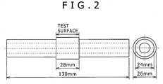
- Fig. 2 illustrates a shape (after finishing) of the roller pitching test specimen.
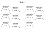
- Tables 3 and 4 show conditions (heating temperature, holding time, and a N 2 fraction (other fractions include C mixed gas (C 3 H 8 ): 1% and a H 2 fraction as the remainder) of such nitriding treatment together with the various patterns (indicated by subscripts (a) to (f)) illustrated in Fig. 1 (Test Nos. 1 to 23).
- Each of the resultant test specimens was subjected to determination of each of phases (area percentage of carbide and area percentage of retained austenite) of a surface-layer part and determination of nitrogen content at a depth of 20 ⁇ m below its surface according to procedures described below, and was subjected to determination of component properties (seizing resistance) according to a procedure described below.
- the area percentage of carbide in the phase was determined in such a manner that each test specimen subjected to nitriding treatment was cut along a cross section, buried in resin, mirror-polished, and etched so as to be formed into a sample, and the area percentage was determined at a depth position of 20 ⁇ m below the surface of the sample using a scanning electron microscope (SEM). Carbon is diffused from the surface layer to the inside through super-carburizing. As a result, a carbon-thickened layer is formed from the surface-layer part to the inside, and carbide is accordingly formed.
- SEM scanning electron microscope
- carbide in the vicinity of the surface is important, i.e., it is necessary that the carbide in the vicinity of the surface exists at least 5% by area percentage.
- the carbide in the vicinity of the surface was difficult to be directly measured.
- carbide at a depth position of 20 ⁇ m below the surface the carbide having substantially the same area percentage as that of carbide in the vicinity of the surface, was defined to be the carbide in the vicinity of the surface, and it was defined to be a requirement of the invention that such carbide had an area percentage of 5% or more.
- An appropriate 9 ⁇ m ⁇ 12 ⁇ m visual field was observed at 8000 magnifications, and a carbide region was identified using an image analysis software and the area percentage of the carbide region was obtained. Such measurement was performed in three visual fields, and the arithmetic mean of the measurement values in the three visual fields was defined to be the area percentage of carbide.
- the nitrogen content of the surface-layer part (at the depth position of 20 ⁇ m below the surface) was determined in such a manner that each of the test specimens was cut along a cross section, buried in resin, and mirror-polished, and then nitrogen content was measured from the surface-layer part to the inside through analysis using an electron probe microanalyzer (EPMA).
- EPMA electron probe microanalyzer
- a roller pitching test was performed as a method of evaluating the component properties.
- the roller pitching test was conducted by a roller pitching tester using the test specimen (a small roller) and a large roller (a counter part) made of high carbon-chromium bearing steel SUJ2.
- the test was conducted under a condition of rotation speed: 1000 rpm, relative slippage ratio: 700%, and oil temperature: 90°C to obtain a rotational frequency before the tester was stopped due to vibration caused by seizing.
- the rotational frequency was used as seizing life while the frequency of 20,000 ⁇ 10 3 was the upper limit.
- a test specimen that was not seized before the frequency of 10,000 ⁇ 10 3 was determined to be excellent in seizing resistance.
- Tables 5 and 6 show results of such determination (the area percentage of carbide, the area percentage of retained Y, the nitrogen content of the surface-layer part, and the seizing life) together with presence or absence of the lubrication film (manganese phosphate was' used as the lubrication film).
- a representation of ">20,000" indicates that seizing did not occur even at the frequency of 20,000 ⁇ 10 3 .
- Table 5 Test No. Area percentage of carbide (%) Area percentage of retained ⁇ (%) Nitrogen content of surface-layer part (%) Lubrication film Seizing life (frequencies, ⁇ 10 3 ) 1 15.6 3.7 5.7 Not provided 18257 2 12.4 2.6 3.
- Test No. 20 a steel type (steel type S) having a low Cr content is used, and while a manufacturing condition is appropriate, the area percentage of carbide cannot be secured, and seizing resistance is degraded.
- Test No. 21 a steel type (steel type T) having an excessive C content is used, which results in insufficient amount of infiltration of carbon during carburizing, and therefore the area percentage of carbide cannot be secured.
- nitrogen content of the surface layer is low, seizing resistance is degraded.
- steel type B is the same as the steel type B shown in Table 1
- steel type B was melted in a small furnace so as to be formed into ingots that were then hot-forged and subjected to solution treatment and normalizing treatment, and were each then crudely machined into a shape of a roller pitching test specimen 26 mm in diameter and 130 mm in length.
- the resultant test specimens were subjected to super-carburizing treatment (carburizing treatment and carbide precipitation treatment) in the heat treatment pattern illustrated in (a) of Fig. 1 . In this operation, each test specimen was cooled at an average cooling rate of 50 °C/sec after the super-carburizing.
- test specimen was then tempered, and then subjected to nitriding treatment (plasma nitrocarburizing treatment or plasma nitriding treatment), so that a phase containing nitrogen in high content was formed in the surface-layer part.
- nitriding treatment plasma nitrocarburizing treatment or plasma nitriding treatment
- the test specimen was finished into a roller pitching test specimen.
- the roller pitching test specimen was subjected to a roller pitching test as in the first embodiment.
- Table 8 shows conditions (heating temperature, holding time, and gas fractions (a fraction of each of N 2 gas, H 2 gas, and C mixed gas) of such nitriding treatment (Test Nos. 24 to 30).
- Table 8 Test No. Steel type Super-carburizing treatment pattern Nitriding condition Heating temperature (°C) Holding time (hour) Gas fraction (%) Nitriding treatment type N 2 fraction H 2 fraction C mixed-gas fraction 24 B (a) 520 5 60 39 C 3 H 8 :1 Plasma nitrocarburizing treatment 25 B (a) 520 5 60 40 O Plasma nitriding treatment 26 B (a) 570 5 60 39 C 3 H 8 :1 Plasma nitrocarburizing treatment 27 B (a) 520 5 40 59 C 3 H 8 :1 Plasma nitrocarburizing treatment 28 W (a) 570 5 60 39 C 3 H 8 :1 Plasma nitrocarburizing treatment 29 X (a) 570 5 60 39 C 3 H 8 :1 Plasma nitrocarburizing treatment 30 Y (a)
- Each of the resultant test specimens was subjected to determination of each of phases (area percentage of carbide and area percentage of retained Y) of a surface-layer part, nitrogen content at a depth of 20 ⁇ m below its surface, and component properties (seizing resistance) according to the procedures as described in the first embodiment, and was subjected to determination of a nitride layer composition according to a procedure described below.
- test specimen Part of each test specimen was sampled, and was subjected to X-ray diffraction under the following condition in a surface-layer part (a surface-layer part ranging from the surface to a depth of 20 ⁇ m) of the test specimen.
- Tube amplifier Co
- monochromating monochrometer (K ⁇ line)
- tube amplifier output 40 kV-26 mA
- detector (two-dimensional) imaging plate.
- Collimator ⁇ 300 ⁇ m, ⁇ angle (X-ray incident angle): 22° to 30°, oscillation (1 °/sec).
- a proportion of iron nitride in the surface layer means a proportion (mass%) of the total relative content of Fe 4 N and Fe 2-3 N in the sum (100 mass%) of relative content of all components that were found to exist in the surface layer as a result of the X-ray diffraction.
- a proportion of Fe 4 N in the iron nitride means a proportion (mass%) of the relative content of Fe 4 N in the total relative content of Fe 4 N and Fe 2-3 N. Values of such proportions were calculated by the following formulas.
- all the components existing in the surface layer of the test specimen include Fe 4 N, F'e 2-3 N, Fe 5 C 2 , Fe 3 C, ⁇ -Fe, ⁇ -Fe, and the like, and the total proportion of such components is basically 100%, but a small amount (5% or less) of each of other components (for example, Fe 2 C, Fe 22 C, Fe 7 C 3 , and the like) may be contained (if such components are contained, the total proportion including such components is 100%).
- Proportion of iron nitride mass % relative content mass % of Fe 4 N in surface layer + relative content mass of Fe 2 ⁇ 3 N in surface layer
- Proportion of Fe 4 N mass % in iron nitride relative content mass % of Fe 4 N ) / relative content mass % of Fe 4 N + relative content mass % of Fe 2 ⁇ 3 N ⁇ 100 %
- Table 9 collectively shows results of such calculations.
- Table 9 Test No. Area percentage of carbide (%) Area percentage of retained ⁇ (%) Nitrogen content of surface-layer part (%) Nitrided layer composition Lubrication film Seizing life (frequencies, ⁇ 10 3 ) Proportion of iron nitride (mass%) Proportion of Fe 4 N (mass%) 24 12.5 3.1 3. 5 73 10 Not provided 13995 25 12.0 2. 9 2.8 85 30 Not provided >20000 26 11.7 1. 9 3.0 90 22 Not provided 19363 27 12. 2 2.6 2. 5 86 38 Not provided > 20000 28 12.1 3. 7 4.3 88 11 Not provided 17428 29 5. 7 1.7 2.6 90 30 Not provided >20000 30 8.2 1.5 3. 5 92 26 Not provided >20000
- any of the area percentage of carbide, the area percentage of retained Y, and the nitrogen content of the surface-layer part can be controlled to be within the range defined in the invention.
- the steel is excellent in adhesion suppression effect, and can exhibit excellent seizing resistance.
- Test Nos. 25 to 27, 29, and 30 further satisfies the preferred requirement of the nitrided layer composition, and exhibits particularly excellent seizing resistance.
- the gear of the invention has a predetermined chemical composition, and has a surface-layer part that includes a steel microstructure including at least one phase of tempered martensite and tempered bainite, 1 to 10% retained austenite by area percentage, and 5% or more carbide being precipitated by area percentage, and the gear has a nitrogen content of 2.0 to 6.0% at a depth of 20 ⁇ m below a surface of the gear, and thereby exhibits more excellent seizing resistance in a power transmission part subjected to high rotation and high slippage, for which the lubricating oil having a low kinematic viscosity is used.
Landscapes
- Chemical & Material Sciences (AREA)
- Engineering & Computer Science (AREA)
- Mechanical Engineering (AREA)
- Organic Chemistry (AREA)
- Materials Engineering (AREA)
- Metallurgy (AREA)
- Thermal Sciences (AREA)
- Physics & Mathematics (AREA)
- Crystallography & Structural Chemistry (AREA)
- Chemical Kinetics & Catalysis (AREA)
- General Engineering & Computer Science (AREA)
- General Chemical & Material Sciences (AREA)
- Oil, Petroleum & Natural Gas (AREA)
- Heat Treatment Of Articles (AREA)
- Solid-Phase Diffusion Into Metallic Material Surfaces (AREA)
- Gears, Cams (AREA)
Claims (4)
- Un engrenage présentant une excellente résistance au grippage, caractérisé en ce qu'il comprend une composition chimique consistante en du C: de 0,15 à 0,45% (en pourcent en masse, même observation ci-après à toutes les compositions chimiques), Si: de 0,05 à 1,0%, Mn: de 1,0 à 2,0%, P: 0,05% ou moins, S: 0,05% ou moins, Cr: de 0,9 à 2%, Al: de 0,01 à 0,1% et N: 0,02% ou moins, facultativement Mo: 0,5% ou moins, facultativement au moins un élément sélectionné parmi le groupe consistant en du V: 0,2% ou moins, Ti: 0,1% ou moins et Nb: 0,2% ou moins, facultativement B: 0,01% ou moins, facultativement au moins un élément sélectionné parmi le groupe consistant en du Cu: 5% ou moins et Ni: 5% ou moins, le reste consistant en du Fe et d'impuretés inévitables, l'engrenage ayant une partie de couche extérieure présentant une microstructure de l'acier incluant au moins une phase de martensite revenue et de bainite revenue, 1 à 10% d'austénite résiduelle en pourcent de surface et 5% ou plus de carbure précipité par pourcent de surface, et l'engrenage ayant une teneur en azote allant de 2,0 à 6,0% à une profondeur de 20 µm en dessous de la surface de l'engrenage.
- L'engrenage selon la revendication 1, dans lequel une couche nitrurée avec une teneur en nitrure de fer de 80% en masse ou plus, est présente dans la partie de couche extérieure allant de la surface à la profondeur de 20 µm, et la couche nitrurée a une proportion de Fe4N de 20% en masse ou plus dans le nitrure de fer.
- L.'engrenage selon la revendication 1, présentant un film de lubrifiant à sa surface.
- Utilisation de l'engrenage selon la revendication 1 dans un moteur de voiture électrique.
Applications Claiming Priority (2)
| Application Number | Priority Date | Filing Date | Title |
|---|---|---|---|
| JP2012082613 | 2012-03-30 | ||
| PCT/JP2013/059737 WO2013147258A1 (fr) | 2012-03-30 | 2013-03-29 | Engrenage ayant une excellente résistance au grippage |
Publications (3)
| Publication Number | Publication Date |
|---|---|
| EP2832877A1 EP2832877A1 (fr) | 2015-02-04 |
| EP2832877A4 EP2832877A4 (fr) | 2016-04-06 |
| EP2832877B1 true EP2832877B1 (fr) | 2017-10-11 |
Family
ID=49260497
Family Applications (1)
| Application Number | Title | Priority Date | Filing Date |
|---|---|---|---|
| EP13767691.2A Active EP2832877B1 (fr) | 2012-03-30 | 2013-03-29 | Engrenage ayant une excellente résistance au grippage |
Country Status (6)
| Country | Link |
|---|---|
| US (1) | US9587288B2 (fr) |
| EP (1) | EP2832877B1 (fr) |
| JP (1) | JP6088322B2 (fr) |
| CN (1) | CN104220621B (fr) |
| TW (1) | TWI507540B (fr) |
| WO (1) | WO2013147258A1 (fr) |
Families Citing this family (16)
| Publication number | Priority date | Publication date | Assignee | Title |
|---|---|---|---|---|
| JP6301145B2 (ja) * | 2014-02-05 | 2018-03-28 | 新日鐵住金株式会社 | スリーブ・ドッグギヤ |
| CN105039867A (zh) * | 2015-09-16 | 2015-11-11 | 广东韶钢松山股份有限公司 | 一种加氮20MnCr5齿轮钢及其生产方法 |
| CN106222605A (zh) * | 2016-08-29 | 2016-12-14 | 盐城圣奥热处理有限公司 | 一种齿轮渗碳淬火工艺 |
| JP6908485B2 (ja) | 2016-09-30 | 2021-07-28 | Dowaサーモテック株式会社 | 連続窒化処理炉および連続窒化処理方法 |
| CN108342640B (zh) * | 2017-01-22 | 2020-03-27 | 宝山钢铁股份有限公司 | 一种高淬透性齿轮钢及其制造方法 |
| CN106834960B (zh) * | 2017-01-24 | 2018-06-01 | 中天钢铁集团有限公司 | 一种汽车用含硼高级齿轮钢及其生产工艺 |
| CN108193121A (zh) * | 2017-12-29 | 2018-06-22 | 重庆全茂合渝科技有限公司 | 一种摩托车用齿轮及其制备工艺 |
| JP6881498B2 (ja) * | 2018-08-27 | 2021-06-02 | Jfeスチール株式会社 | 部品およびその製造方法 |
| JP7273324B2 (ja) | 2018-10-29 | 2023-05-15 | 日本製鉄株式会社 | 窒化部品粗形材、および窒化部品 |
| JP7365773B2 (ja) | 2019-02-13 | 2023-10-20 | 株式会社日立製作所 | 軟磁性材料及びその製造方法並びに軟磁性材料を用いた電動機 |
| JP7339560B2 (ja) * | 2019-04-02 | 2023-09-06 | 日本製鉄株式会社 | 窒化部品 |
| US11149832B2 (en) * | 2019-12-13 | 2021-10-19 | Aichi Steel Corporation | Differential hypoid gear, pinion gear, and paired hypoid gears formed by combination thereof |
| CN111500830B (zh) * | 2020-05-28 | 2021-02-26 | 中国矿业大学 | 一种渗碳零件回火热处理方法及渗碳零件 |
| JP7755131B2 (ja) * | 2021-09-03 | 2025-10-16 | 日本製鉄株式会社 | 窒化高周波焼入れ用鋼および窒化高周波焼入れ部品 |
| TWI789124B (zh) * | 2021-11-19 | 2023-01-01 | 財團法人金屬工業研究發展中心 | 碳鋼元件的製造方法 |
| CN116555680B (zh) * | 2023-04-11 | 2025-03-07 | 江阴兴澄特种钢铁有限公司 | 一种新能源汽车高强度减速器齿轮用钢及其制造方法 |
Family Cites Families (27)
| Publication number | Priority date | Publication date | Assignee | Title |
|---|---|---|---|---|
| JPS62211094A (ja) | 1986-03-12 | 1987-09-17 | 株式会社廣瀬製作所 | ミシンのかまの製造方法 |
| JP3145517B2 (ja) | 1992-12-09 | 2001-03-12 | 株式会社神戸製鋼所 | 疲労強度特に面疲労強度に優れた機械構造用部品およびその製造方法 |
| DE69422146T2 (de) * | 1993-03-31 | 2000-08-24 | Hitachi Metals, Ltd. | GEGEN VERSCHLEISS UND FRESSEN WIDERSTANDSFäHIGE WALZE ZUM WARMWALZEN |
| EP0800538B1 (fr) * | 1994-12-30 | 2001-05-09 | Eastman Chemical Company | Procede de preparation d'esters cellulosiques a l'aide d'un catalyseur de resine d'acide sulfonique |
| JP3524229B2 (ja) * | 1995-08-11 | 2004-05-10 | 株式会社神戸製鋼所 | 高靭性肌焼き鋼製機械部品およびその製法 |
| JP3410947B2 (ja) | 1998-01-09 | 2003-05-26 | 日産自動車株式会社 | 無段変速機の転動体およびその製造方法 |
| JP2002286115A (ja) | 2001-03-23 | 2002-10-03 | Nissan Motor Co Ltd | 高強度歯車及びその製造方法 |
| JP4390576B2 (ja) * | 2003-03-04 | 2009-12-24 | 株式会社小松製作所 | 転動部材 |
| JP4390526B2 (ja) * | 2003-03-11 | 2009-12-24 | 株式会社小松製作所 | 転動部材およびその製造方法 |
| JP2005068453A (ja) | 2003-08-28 | 2005-03-17 | Nissan Motor Co Ltd | 耐高面圧部品及びその製造方法 |
| JP2005232543A (ja) | 2004-02-20 | 2005-09-02 | Nsk Ltd | ボールねじ |
| JP4352261B2 (ja) | 2005-02-21 | 2009-10-28 | 住友金属工業株式会社 | 歯車 |
| JP4970811B2 (ja) | 2006-03-13 | 2012-07-11 | 山陽特殊製鋼株式会社 | 高面圧用部品とその製造方法 |
| JP4725401B2 (ja) | 2006-04-14 | 2011-07-13 | 住友金属工業株式会社 | 鋼製部品及びその製造方法 |
| JP4688727B2 (ja) | 2006-05-19 | 2011-05-25 | 株式会社神戸製鋼所 | 浸炭部品およびその製造方法 |
| RU2437958C1 (ru) | 2007-10-24 | 2011-12-27 | Ниппон Стил Корпорейшн | Нитроцементированная стальная деталь с индукционной закалкой с повышенной усталостной прочностью поверхности при высокой температуре и способ ее производства |
| US20090192063A1 (en) * | 2008-01-25 | 2009-07-30 | Afton Chemical Corporation | Final Drive and Powershift Transmission Lubricants |
| JP5207805B2 (ja) | 2008-04-08 | 2013-06-12 | 株式会社神戸製鋼所 | 曲げ疲労強度に優れた鋼部品、及びその製造方法 |
| JP5206271B2 (ja) | 2008-09-22 | 2013-06-12 | 新日鐵住金株式会社 | 鋼製の浸炭窒化部品 |
| US20110041959A1 (en) | 2008-12-19 | 2011-02-24 | Atsushi Mizuno | Steel for machine structure use for surface hardening and steel part for machine structure use |
| JP5182067B2 (ja) | 2008-12-24 | 2013-04-10 | 新日鐵住金株式会社 | 真空浸炭または真空浸炭窒化用の鋼材 |
| ES2731643T3 (es) | 2009-01-16 | 2019-11-18 | Nippon Steel Corp | Acero para endurecimiento de superficies para uso estructural en máquinas y componente para uso estructural en máquinas |
| CN102089452A (zh) * | 2009-05-15 | 2011-06-08 | 新日本制铁株式会社 | 软氮化用钢和软氮化处理部件 |
| JP5644166B2 (ja) * | 2010-04-20 | 2014-12-24 | 大同特殊鋼株式会社 | 水素脆性型の面疲労強度に優れた浸炭窒化鋼 |
| JP5632659B2 (ja) | 2010-06-17 | 2014-11-26 | 株式会社神戸製鋼所 | 熱処理歪みの少ない肌焼鋼 |
| KR20130036763A (ko) | 2010-08-12 | 2013-04-12 | 제이에프이 스틸 가부시키가이샤 | 가공성 및 내충격성이 우수한 고강도 냉연 강판 및 그 제조 방법 |
| TWI475114B (zh) | 2010-08-18 | 2015-03-01 | Jfe Steel Corp | High strength cold rolled steel sheet excellent in workability and impact resistance and a method of manufacturing the same |
-
2013
- 2013-03-29 JP JP2013075191A patent/JP6088322B2/ja active Active
- 2013-03-29 EP EP13767691.2A patent/EP2832877B1/fr active Active
- 2013-03-29 CN CN201380017469.XA patent/CN104220621B/zh active Active
- 2013-03-29 TW TW102111634A patent/TWI507540B/zh active
- 2013-03-29 US US14/383,726 patent/US9587288B2/en active Active
- 2013-03-29 WO PCT/JP2013/059737 patent/WO2013147258A1/fr not_active Ceased
Non-Patent Citations (1)
| Title |
|---|
| None * |
Also Published As
| Publication number | Publication date |
|---|---|
| US20150038380A1 (en) | 2015-02-05 |
| EP2832877A1 (fr) | 2015-02-04 |
| TWI507540B (zh) | 2015-11-11 |
| EP2832877A4 (fr) | 2016-04-06 |
| CN104220621B (zh) | 2017-04-12 |
| CN104220621A (zh) | 2014-12-17 |
| JP2013227674A (ja) | 2013-11-07 |
| JP6088322B2 (ja) | 2017-03-01 |
| TW201408790A (zh) | 2014-03-01 |
| US9587288B2 (en) | 2017-03-07 |
| WO2013147258A1 (fr) | 2013-10-03 |
Similar Documents
| Publication | Publication Date | Title |
|---|---|---|
| EP2832877B1 (fr) | Engrenage ayant une excellente résistance au grippage | |
| EP3088550B1 (fr) | Procédé de production de constituant en acier cémenté et constituant en acier cémenté | |
| EP2381003B1 (fr) | Acier pour durcissement à haute fréquence | |
| EP2514847A1 (fr) | Acier pour traitement de cémentation, composant en acier cémenté, et son procédé de production | |
| JP6737387B2 (ja) | 軟窒化用鋼および部品 | |
| EP2816128B1 (fr) | Acier à nitruration modérée et matière d'acier utilisant un composant à nitruration modérée | |
| WO2012077705A1 (fr) | Composant d'acier de cémentation gazeuse ayant une excellente résistance à la fatigue de surface, matériau d'acier de cémentation gazeuse et procédé de fabrication d'un composant d'acier de cémentation gazeuse | |
| EP2647734B1 (fr) | Acier à roulement présentant une excellente aptitude à l'usinage après un recuit de sphéroïdisation et une excellente résistance à la fatigue due à l'hydrogène après une trempe/un revenu | |
| EP1847631B1 (fr) | Composant cémenté et son procédé de fabrication | |
| EP3276023B1 (fr) | Acier pour nitrocarburation und composants nitrocarburé, et son procédé de fabrication | |
| JP6111121B2 (ja) | 耐焼付き性に優れた歯車 | |
| JP4451808B2 (ja) | 疲労特性と耐結晶粒粗大化特性に優れた肌焼用圧延棒鋼およびその製法 | |
| EP3875610B1 (fr) | Acier pour nitrocarburisation et composant nitrocarburé, et son procédé de fabrication | |
| JP3353698B2 (ja) | 軟窒化用鋼材の製造方法及びその鋼材を用いた軟窒化部品 | |
| JP7755132B2 (ja) | 窒化高周波焼入れ用鋼および窒化高周波焼入れ部品 | |
| JP7755131B2 (ja) | 窒化高周波焼入れ用鋼および窒化高周波焼入れ部品 | |
| JP7684828B2 (ja) | 浸炭部品 | |
| JP2006161143A (ja) | 転動疲労寿命と高温浸炭特性に優れた浸炭用鋼材 | |
| JPH11335732A (ja) | 軟窒化用鋼材の製造方法及びその鋼材を用いた軟窒化部品 | |
| JP2024034953A (ja) | 鋼材及び鋼部品 | |
| TW201730354A (zh) | 滲碳氮化用鋼材及滲碳氮化零件 | |
| CN118202078A (zh) | 滑动部件用钢材和滑动部件用钢材的制造方法 | |
| JP2023097583A (ja) | 鋼、および、浸炭焼入れ部品 | |
| JP2023069388A (ja) | 鋼、および、浸炭焼入れ部品 |
Legal Events
| Date | Code | Title | Description |
|---|---|---|---|
| PUAI | Public reference made under article 153(3) epc to a published international application that has entered the european phase |
Free format text: ORIGINAL CODE: 0009012 |
|
| 17P | Request for examination filed |
Effective date: 20140911 |
|
| AK | Designated contracting states |
Kind code of ref document: A1 Designated state(s): AL AT BE BG CH CY CZ DE DK EE ES FI FR GB GR HR HU IE IS IT LI LT LU LV MC MK MT NL NO PL PT RO RS SE SI SK SM TR |
|
| AX | Request for extension of the european patent |
Extension state: BA ME |
|
| DAX | Request for extension of the european patent (deleted) | ||
| RA4 | Supplementary search report drawn up and despatched (corrected) |
Effective date: 20160309 |
|
| REG | Reference to a national code |
Ref country code: DE Ref legal event code: R079 Ref document number: 602013027831 Country of ref document: DE Free format text: PREVIOUS MAIN CLASS: C22C0038000000 Ipc: F16H0055060000 |
|
| RIC1 | Information provided on ipc code assigned before grant |
Ipc: C22C 38/28 20060101ALI20170207BHEP Ipc: C23C 8/80 20060101ALI20170207BHEP Ipc: C22C 38/38 20060101ALI20170207BHEP Ipc: C22C 38/08 20060101ALI20170207BHEP Ipc: C22C 38/22 20060101ALI20170207BHEP Ipc: F16H 55/06 20060101AFI20170207BHEP Ipc: C21D 9/32 20060101ALI20170207BHEP Ipc: C22C 38/16 20060101ALI20170207BHEP Ipc: C22C 38/58 20060101ALI20170207BHEP Ipc: C22C 38/32 20060101ALI20170207BHEP Ipc: C22C 38/24 20060101ALI20170207BHEP Ipc: C22C 38/42 20060101ALI20170207BHEP Ipc: C22C 38/02 20060101ALI20170207BHEP Ipc: C22C 38/06 20060101ALI20170207BHEP Ipc: C22C 38/26 20060101ALI20170207BHEP Ipc: C23C 8/26 20060101ALI20170207BHEP Ipc: C21D 1/06 20060101ALI20170207BHEP Ipc: C23C 8/34 20060101ALI20170207BHEP Ipc: C22C 38/12 20060101ALI20170207BHEP Ipc: C22C 38/00 20060101ALI20170207BHEP |
|
| GRAP | Despatch of communication of intention to grant a patent |
Free format text: ORIGINAL CODE: EPIDOSNIGR1 |
|
| INTG | Intention to grant announced |
Effective date: 20170321 |
|
| GRAS | Grant fee paid |
Free format text: ORIGINAL CODE: EPIDOSNIGR3 |
|
| GRAJ | Information related to disapproval of communication of intention to grant by the applicant or resumption of examination proceedings by the epo deleted |
Free format text: ORIGINAL CODE: EPIDOSDIGR1 |
|
| GRAL | Information related to payment of fee for publishing/printing deleted |
Free format text: ORIGINAL CODE: EPIDOSDIGR3 |
|
| GRAR | Information related to intention to grant a patent recorded |
Free format text: ORIGINAL CODE: EPIDOSNIGR71 |
|
| GRAA | (expected) grant |
Free format text: ORIGINAL CODE: 0009210 |
|
| INTC | Intention to grant announced (deleted) | ||
| INTG | Intention to grant announced |
Effective date: 20170831 |
|
| AK | Designated contracting states |
Kind code of ref document: B1 Designated state(s): AL AT BE BG CH CY CZ DE DK EE ES FI FR GB GR HR HU IE IS IT LI LT LU LV MC MK MT NL NO PL PT RO RS SE SI SK SM TR |
|
| REG | Reference to a national code |
Ref country code: GB Ref legal event code: FG4D |
|
| REG | Reference to a national code |
Ref country code: CH Ref legal event code: EP |
|
| REG | Reference to a national code |
Ref country code: IE Ref legal event code: FG4D |
|
| REG | Reference to a national code |
Ref country code: AT Ref legal event code: REF Ref document number: 936352 Country of ref document: AT Kind code of ref document: T Effective date: 20171115 |
|
| REG | Reference to a national code |
Ref country code: DE Ref legal event code: R096 Ref document number: 602013027831 Country of ref document: DE |
|
| REG | Reference to a national code |
Ref country code: NL Ref legal event code: MP Effective date: 20171011 |
|
| REG | Reference to a national code |
Ref country code: LT Ref legal event code: MG4D |
|
| REG | Reference to a national code |
Ref country code: FR Ref legal event code: PLFP Year of fee payment: 6 |
|
| REG | Reference to a national code |
Ref country code: AT Ref legal event code: MK05 Ref document number: 936352 Country of ref document: AT Kind code of ref document: T Effective date: 20171011 |
|
| PG25 | Lapsed in a contracting state [announced via postgrant information from national office to epo] |
Ref country code: NL Free format text: LAPSE BECAUSE OF FAILURE TO SUBMIT A TRANSLATION OF THE DESCRIPTION OR TO PAY THE FEE WITHIN THE PRESCRIBED TIME-LIMIT Effective date: 20171011 |
|
| PG25 | Lapsed in a contracting state [announced via postgrant information from national office to epo] |
Ref country code: LT Free format text: LAPSE BECAUSE OF FAILURE TO SUBMIT A TRANSLATION OF THE DESCRIPTION OR TO PAY THE FEE WITHIN THE PRESCRIBED TIME-LIMIT Effective date: 20171011 Ref country code: SE Free format text: LAPSE BECAUSE OF FAILURE TO SUBMIT A TRANSLATION OF THE DESCRIPTION OR TO PAY THE FEE WITHIN THE PRESCRIBED TIME-LIMIT Effective date: 20171011 Ref country code: FI Free format text: LAPSE BECAUSE OF FAILURE TO SUBMIT A TRANSLATION OF THE DESCRIPTION OR TO PAY THE FEE WITHIN THE PRESCRIBED TIME-LIMIT Effective date: 20171011 Ref country code: NO Free format text: LAPSE BECAUSE OF FAILURE TO SUBMIT A TRANSLATION OF THE DESCRIPTION OR TO PAY THE FEE WITHIN THE PRESCRIBED TIME-LIMIT Effective date: 20180111 Ref country code: ES Free format text: LAPSE BECAUSE OF FAILURE TO SUBMIT A TRANSLATION OF THE DESCRIPTION OR TO PAY THE FEE WITHIN THE PRESCRIBED TIME-LIMIT Effective date: 20171011 |
|
| PG25 | Lapsed in a contracting state [announced via postgrant information from national office to epo] |
Ref country code: GR Free format text: LAPSE BECAUSE OF FAILURE TO SUBMIT A TRANSLATION OF THE DESCRIPTION OR TO PAY THE FEE WITHIN THE PRESCRIBED TIME-LIMIT Effective date: 20180112 Ref country code: BG Free format text: LAPSE BECAUSE OF FAILURE TO SUBMIT A TRANSLATION OF THE DESCRIPTION OR TO PAY THE FEE WITHIN THE PRESCRIBED TIME-LIMIT Effective date: 20180111 Ref country code: HR Free format text: LAPSE BECAUSE OF FAILURE TO SUBMIT A TRANSLATION OF THE DESCRIPTION OR TO PAY THE FEE WITHIN THE PRESCRIBED TIME-LIMIT Effective date: 20171011 Ref country code: IS Free format text: LAPSE BECAUSE OF FAILURE TO SUBMIT A TRANSLATION OF THE DESCRIPTION OR TO PAY THE FEE WITHIN THE PRESCRIBED TIME-LIMIT Effective date: 20180211 Ref country code: LV Free format text: LAPSE BECAUSE OF FAILURE TO SUBMIT A TRANSLATION OF THE DESCRIPTION OR TO PAY THE FEE WITHIN THE PRESCRIBED TIME-LIMIT Effective date: 20171011 Ref country code: AT Free format text: LAPSE BECAUSE OF FAILURE TO SUBMIT A TRANSLATION OF THE DESCRIPTION OR TO PAY THE FEE WITHIN THE PRESCRIBED TIME-LIMIT Effective date: 20171011 Ref country code: RS Free format text: LAPSE BECAUSE OF FAILURE TO SUBMIT A TRANSLATION OF THE DESCRIPTION OR TO PAY THE FEE WITHIN THE PRESCRIBED TIME-LIMIT Effective date: 20171011 |
|
| REG | Reference to a national code |
Ref country code: DE Ref legal event code: R097 Ref document number: 602013027831 Country of ref document: DE |
|
| PG25 | Lapsed in a contracting state [announced via postgrant information from national office to epo] |
Ref country code: SK Free format text: LAPSE BECAUSE OF FAILURE TO SUBMIT A TRANSLATION OF THE DESCRIPTION OR TO PAY THE FEE WITHIN THE PRESCRIBED TIME-LIMIT Effective date: 20171011 Ref country code: CZ Free format text: LAPSE BECAUSE OF FAILURE TO SUBMIT A TRANSLATION OF THE DESCRIPTION OR TO PAY THE FEE WITHIN THE PRESCRIBED TIME-LIMIT Effective date: 20171011 Ref country code: DK Free format text: LAPSE BECAUSE OF FAILURE TO SUBMIT A TRANSLATION OF THE DESCRIPTION OR TO PAY THE FEE WITHIN THE PRESCRIBED TIME-LIMIT Effective date: 20171011 Ref country code: EE Free format text: LAPSE BECAUSE OF FAILURE TO SUBMIT A TRANSLATION OF THE DESCRIPTION OR TO PAY THE FEE WITHIN THE PRESCRIBED TIME-LIMIT Effective date: 20171011 |
|
| PLBE | No opposition filed within time limit |
Free format text: ORIGINAL CODE: 0009261 |
|
| STAA | Information on the status of an ep patent application or granted ep patent |
Free format text: STATUS: NO OPPOSITION FILED WITHIN TIME LIMIT |
|
| PG25 | Lapsed in a contracting state [announced via postgrant information from national office to epo] |
Ref country code: PL Free format text: LAPSE BECAUSE OF FAILURE TO SUBMIT A TRANSLATION OF THE DESCRIPTION OR TO PAY THE FEE WITHIN THE PRESCRIBED TIME-LIMIT Effective date: 20171011 Ref country code: SM Free format text: LAPSE BECAUSE OF FAILURE TO SUBMIT A TRANSLATION OF THE DESCRIPTION OR TO PAY THE FEE WITHIN THE PRESCRIBED TIME-LIMIT Effective date: 20171011 Ref country code: RO Free format text: LAPSE BECAUSE OF FAILURE TO SUBMIT A TRANSLATION OF THE DESCRIPTION OR TO PAY THE FEE WITHIN THE PRESCRIBED TIME-LIMIT Effective date: 20171011 Ref country code: IT Free format text: LAPSE BECAUSE OF FAILURE TO SUBMIT A TRANSLATION OF THE DESCRIPTION OR TO PAY THE FEE WITHIN THE PRESCRIBED TIME-LIMIT Effective date: 20171011 |
|
| 26N | No opposition filed |
Effective date: 20180712 |
|
| REG | Reference to a national code |
Ref country code: CH Ref legal event code: PL |
|
| GBPC | Gb: european patent ceased through non-payment of renewal fee |
Effective date: 20180329 |
|
| PG25 | Lapsed in a contracting state [announced via postgrant information from national office to epo] |
Ref country code: SI Free format text: LAPSE BECAUSE OF FAILURE TO SUBMIT A TRANSLATION OF THE DESCRIPTION OR TO PAY THE FEE WITHIN THE PRESCRIBED TIME-LIMIT Effective date: 20171011 Ref country code: MC Free format text: LAPSE BECAUSE OF FAILURE TO SUBMIT A TRANSLATION OF THE DESCRIPTION OR TO PAY THE FEE WITHIN THE PRESCRIBED TIME-LIMIT Effective date: 20171011 |
|
| REG | Reference to a national code |
Ref country code: BE Ref legal event code: MM Effective date: 20180331 |
|
| REG | Reference to a national code |
Ref country code: IE Ref legal event code: MM4A |
|
| PG25 | Lapsed in a contracting state [announced via postgrant information from national office to epo] |
Ref country code: LU Free format text: LAPSE BECAUSE OF NON-PAYMENT OF DUE FEES Effective date: 20180329 |
|
| PG25 | Lapsed in a contracting state [announced via postgrant information from national office to epo] |
Ref country code: IE Free format text: LAPSE BECAUSE OF NON-PAYMENT OF DUE FEES Effective date: 20180329 |
|
| PG25 | Lapsed in a contracting state [announced via postgrant information from national office to epo] |
Ref country code: LI Free format text: LAPSE BECAUSE OF NON-PAYMENT OF DUE FEES Effective date: 20180331 Ref country code: GB Free format text: LAPSE BECAUSE OF NON-PAYMENT OF DUE FEES Effective date: 20180329 Ref country code: CH Free format text: LAPSE BECAUSE OF NON-PAYMENT OF DUE FEES Effective date: 20180331 Ref country code: BE Free format text: LAPSE BECAUSE OF NON-PAYMENT OF DUE FEES Effective date: 20180331 |
|
| PG25 | Lapsed in a contracting state [announced via postgrant information from national office to epo] |
Ref country code: MT Free format text: LAPSE BECAUSE OF NON-PAYMENT OF DUE FEES Effective date: 20180329 |
|
| PG25 | Lapsed in a contracting state [announced via postgrant information from national office to epo] |
Ref country code: TR Free format text: LAPSE BECAUSE OF FAILURE TO SUBMIT A TRANSLATION OF THE DESCRIPTION OR TO PAY THE FEE WITHIN THE PRESCRIBED TIME-LIMIT Effective date: 20171011 |
|
| PG25 | Lapsed in a contracting state [announced via postgrant information from national office to epo] |
Ref country code: PT Free format text: LAPSE BECAUSE OF FAILURE TO SUBMIT A TRANSLATION OF THE DESCRIPTION OR TO PAY THE FEE WITHIN THE PRESCRIBED TIME-LIMIT Effective date: 20171011 |
|
| PG25 | Lapsed in a contracting state [announced via postgrant information from national office to epo] |
Ref country code: MK Free format text: LAPSE BECAUSE OF NON-PAYMENT OF DUE FEES Effective date: 20171011 Ref country code: CY Free format text: LAPSE BECAUSE OF FAILURE TO SUBMIT A TRANSLATION OF THE DESCRIPTION OR TO PAY THE FEE WITHIN THE PRESCRIBED TIME-LIMIT Effective date: 20171011 Ref country code: HU Free format text: LAPSE BECAUSE OF FAILURE TO SUBMIT A TRANSLATION OF THE DESCRIPTION OR TO PAY THE FEE WITHIN THE PRESCRIBED TIME-LIMIT; INVALID AB INITIO Effective date: 20130329 |
|
| PG25 | Lapsed in a contracting state [announced via postgrant information from national office to epo] |
Ref country code: AL Free format text: LAPSE BECAUSE OF FAILURE TO SUBMIT A TRANSLATION OF THE DESCRIPTION OR TO PAY THE FEE WITHIN THE PRESCRIBED TIME-LIMIT Effective date: 20171011 |
|
| P01 | Opt-out of the competence of the unified patent court (upc) registered |
Effective date: 20230523 |
|
| PGFP | Annual fee paid to national office [announced via postgrant information from national office to epo] |
Ref country code: FR Payment date: 20251231 Year of fee payment: 14 |
|
| PGFP | Annual fee paid to national office [announced via postgrant information from national office to epo] |
Ref country code: DE Payment date: 20260102 Year of fee payment: 14 |