EP2833450A1 - Poröses elektrodenbasismaterial, verfahren zur herstellung davon und vorläuferfolie - Google Patents
Poröses elektrodenbasismaterial, verfahren zur herstellung davon und vorläuferfolie Download PDFInfo
- Publication number
- EP2833450A1 EP2833450A1 EP13767284.6A EP13767284A EP2833450A1 EP 2833450 A1 EP2833450 A1 EP 2833450A1 EP 13767284 A EP13767284 A EP 13767284A EP 2833450 A1 EP2833450 A1 EP 2833450A1
- Authority
- EP
- European Patent Office
- Prior art keywords
- sheet
- fibers
- carbon fibers
- resin
- phenolic resin
- Prior art date
- Legal status (The legal status is an assumption and is not a legal conclusion. Google has not performed a legal analysis and makes no representation as to the accuracy of the status listed.)
- Ceased
Links
- 239000002243 precursor Substances 0.000 title claims abstract description 163
- 239000000463 material Substances 0.000 title claims abstract description 145
- 238000004519 manufacturing process Methods 0.000 title claims abstract description 71
- 238000000034 method Methods 0.000 title claims abstract description 71
- OKTJSMMVPCPJKN-UHFFFAOYSA-N Carbon Chemical compound [C] OKTJSMMVPCPJKN-UHFFFAOYSA-N 0.000 claims abstract description 298
- 229920000049 Carbon (fiber) Polymers 0.000 claims abstract description 237
- 239000004917 carbon fiber Substances 0.000 claims abstract description 237
- 229920001568 phenolic resin Polymers 0.000 claims abstract description 150
- 239000005011 phenolic resin Substances 0.000 claims abstract description 150
- KXGFMDJXCMQABM-UHFFFAOYSA-N 2-methoxy-6-methylphenol Chemical compound [CH]OC1=CC=CC([CH])=C1O KXGFMDJXCMQABM-UHFFFAOYSA-N 0.000 claims abstract description 137
- XLYOFNOQVPJJNP-UHFFFAOYSA-N water Substances O XLYOFNOQVPJJNP-UHFFFAOYSA-N 0.000 claims abstract description 133
- 238000010000 carbonizing Methods 0.000 claims abstract description 9
- 239000000835 fiber Substances 0.000 claims description 243
- 229920005989 resin Polymers 0.000 claims description 154
- 239000011347 resin Substances 0.000 claims description 154
- 238000011282 treatment Methods 0.000 claims description 83
- 239000011148 porous material Substances 0.000 claims description 69
- 239000002344 surface layer Substances 0.000 claims description 62
- 239000006185 dispersion Substances 0.000 claims description 52
- VNWKTOKETHGBQD-UHFFFAOYSA-N methane Chemical compound C VNWKTOKETHGBQD-UHFFFAOYSA-N 0.000 claims description 45
- 238000010438 heat treatment Methods 0.000 claims description 42
- 238000001035 drying Methods 0.000 claims description 39
- 239000007787 solid Substances 0.000 claims description 38
- 239000002245 particle Substances 0.000 claims description 22
- YCKRFDGAMUMZLT-UHFFFAOYSA-N Fluorine atom Chemical compound [F] YCKRFDGAMUMZLT-UHFFFAOYSA-N 0.000 claims description 21
- 229910052731 fluorine Inorganic materials 0.000 claims description 21
- 239000011737 fluorine Substances 0.000 claims description 21
- 230000002940 repellent Effects 0.000 claims description 12
- 239000005871 repellent Substances 0.000 claims description 12
- 239000000047 product Substances 0.000 description 115
- 229920000642 polymer Polymers 0.000 description 42
- 238000003763 carbonization Methods 0.000 description 29
- 239000007789 gas Substances 0.000 description 29
- 239000007788 liquid Substances 0.000 description 29
- 239000002131 composite material Substances 0.000 description 26
- 238000007906 compression Methods 0.000 description 24
- 230000006835 compression Effects 0.000 description 24
- 229910052799 carbon Inorganic materials 0.000 description 23
- 229910002804 graphite Inorganic materials 0.000 description 23
- 239000002002 slurry Substances 0.000 description 23
- 239000010439 graphite Substances 0.000 description 21
- 239000000243 solution Substances 0.000 description 21
- 239000000446 fuel Substances 0.000 description 18
- 229920000058 polyacrylate Polymers 0.000 description 17
- 239000010410 layer Substances 0.000 description 16
- 230000035699 permeability Effects 0.000 description 16
- NLHHRLWOUZZQLW-UHFFFAOYSA-N Acrylonitrile Chemical compound C=CC#N NLHHRLWOUZZQLW-UHFFFAOYSA-N 0.000 description 13
- 239000002904 solvent Substances 0.000 description 13
- 238000010009 beating Methods 0.000 description 12
- 238000009987 spinning Methods 0.000 description 12
- 239000000178 monomer Substances 0.000 description 11
- 229920002239 polyacrylonitrile Polymers 0.000 description 11
- 239000007921 spray Substances 0.000 description 11
- 239000011550 stock solution Substances 0.000 description 11
- 239000000203 mixture Substances 0.000 description 10
- 229920001342 Bakelite® Polymers 0.000 description 9
- 239000011230 binding agent Substances 0.000 description 9
- -1 perfluoroalkyl vinyl ether Chemical compound 0.000 description 9
- 229920001343 polytetrafluoroethylene Polymers 0.000 description 9
- 239000004810 polytetrafluoroethylene Substances 0.000 description 9
- 238000005507 spraying Methods 0.000 description 9
- 239000006229 carbon black Substances 0.000 description 8
- 238000012360 testing method Methods 0.000 description 8
- 230000018044 dehydration Effects 0.000 description 7
- 238000006297 dehydration reaction Methods 0.000 description 7
- 239000002270 dispersing agent Substances 0.000 description 7
- 239000003273 ketjen black Substances 0.000 description 7
- 238000005498 polishing Methods 0.000 description 7
- 238000003825 pressing Methods 0.000 description 7
- 239000011134 resol-type phenolic resin Substances 0.000 description 7
- ZWEHNKRNPOVVGH-UHFFFAOYSA-N 2-Butanone Chemical compound CCC(C)=O ZWEHNKRNPOVVGH-UHFFFAOYSA-N 0.000 description 6
- OKKJLVBELUTLKV-UHFFFAOYSA-N Methanol Chemical compound OC OKKJLVBELUTLKV-UHFFFAOYSA-N 0.000 description 6
- ZMXDDKWLCZADIW-UHFFFAOYSA-N N,N-Dimethylformamide Chemical compound CN(C)C=O ZMXDDKWLCZADIW-UHFFFAOYSA-N 0.000 description 6
- 239000004372 Polyvinyl alcohol Substances 0.000 description 6
- 239000007833 carbon precursor Substances 0.000 description 6
- 238000005520 cutting process Methods 0.000 description 6
- 239000003960 organic solvent Substances 0.000 description 6
- 229920002451 polyvinyl alcohol Polymers 0.000 description 6
- 239000000126 substance Substances 0.000 description 6
- 239000000725 suspension Substances 0.000 description 6
- 229920000297 Rayon Polymers 0.000 description 5
- 239000012298 atmosphere Substances 0.000 description 5
- 239000003054 catalyst Substances 0.000 description 5
- 230000008602 contraction Effects 0.000 description 5
- 230000001747 exhibiting effect Effects 0.000 description 5
- 238000001764 infiltration Methods 0.000 description 5
- 230000008595 infiltration Effects 0.000 description 5
- 239000002609 medium Substances 0.000 description 5
- NIXOWILDQLNWCW-UHFFFAOYSA-N 2-Propenoic acid Natural products OC(=O)C=C NIXOWILDQLNWCW-UHFFFAOYSA-N 0.000 description 4
- 229920002972 Acrylic fiber Polymers 0.000 description 4
- IJGRMHOSHXDMSA-UHFFFAOYSA-N Atomic nitrogen Chemical compound N#N IJGRMHOSHXDMSA-UHFFFAOYSA-N 0.000 description 4
- LFQSCWFLJHTTHZ-UHFFFAOYSA-N Ethanol Chemical compound CCO LFQSCWFLJHTTHZ-UHFFFAOYSA-N 0.000 description 4
- 229910000831 Steel Inorganic materials 0.000 description 4
- 229920002301 cellulose acetate Polymers 0.000 description 4
- 238000005345 coagulation Methods 0.000 description 4
- 230000000052 comparative effect Effects 0.000 description 4
- 229920001577 copolymer Polymers 0.000 description 4
- 238000012423 maintenance Methods 0.000 description 4
- 239000012528 membrane Substances 0.000 description 4
- 239000005518 polymer electrolyte Substances 0.000 description 4
- 239000011164 primary particle Substances 0.000 description 4
- 238000004080 punching Methods 0.000 description 4
- 239000010959 steel Substances 0.000 description 4
- 238000003756 stirring Methods 0.000 description 4
- BQCIDUSAKPWEOX-UHFFFAOYSA-N 1,1-Difluoroethene Chemical compound FC(F)=C BQCIDUSAKPWEOX-UHFFFAOYSA-N 0.000 description 3
- QTBSBXVTEAMEQO-UHFFFAOYSA-N Acetic acid Chemical compound CC(O)=O QTBSBXVTEAMEQO-UHFFFAOYSA-N 0.000 description 3
- 239000002033 PVDF binder Substances 0.000 description 3
- 239000006230 acetylene black Substances 0.000 description 3
- 239000007864 aqueous solution Substances 0.000 description 3
- 238000000889 atomisation Methods 0.000 description 3
- 238000004364 calculation method Methods 0.000 description 3
- 229920003174 cellulose-based polymer Polymers 0.000 description 3
- 238000009792 diffusion process Methods 0.000 description 3
- 238000010790 dilution Methods 0.000 description 3
- 239000012895 dilution Substances 0.000 description 3
- 239000002612 dispersion medium Substances 0.000 description 3
- 238000009826 distribution Methods 0.000 description 3
- 230000000694 effects Effects 0.000 description 3
- 239000002737 fuel gas Substances 0.000 description 3
- 238000005470 impregnation Methods 0.000 description 3
- 230000004807 localization Effects 0.000 description 3
- 229920000620 organic polymer Polymers 0.000 description 3
- 230000003647 oxidation Effects 0.000 description 3
- 238000007254 oxidation reaction Methods 0.000 description 3
- ISWSIDIOOBJBQZ-UHFFFAOYSA-N phenol group Chemical group C1(=CC=CC=C1)O ISWSIDIOOBJBQZ-UHFFFAOYSA-N 0.000 description 3
- 229920002981 polyvinylidene fluoride Polymers 0.000 description 3
- 239000000843 powder Substances 0.000 description 3
- 238000010248 power generation Methods 0.000 description 3
- 238000012545 processing Methods 0.000 description 3
- 239000004094 surface-active agent Substances 0.000 description 3
- YSYRISKCBOPJRG-UHFFFAOYSA-N 4,5-difluoro-2,2-bis(trifluoromethyl)-1,3-dioxole Chemical compound FC1=C(F)OC(C(F)(F)F)(C(F)(F)F)O1 YSYRISKCBOPJRG-UHFFFAOYSA-N 0.000 description 2
- 229920000178 Acrylic resin Polymers 0.000 description 2
- 239000004925 Acrylic resin Substances 0.000 description 2
- SOGAXMICEFXMKE-UHFFFAOYSA-N Butylmethacrylate Chemical compound CCCCOC(=O)C(C)=C SOGAXMICEFXMKE-UHFFFAOYSA-N 0.000 description 2
- RYGMFSIKBFXOCR-UHFFFAOYSA-N Copper Chemical compound [Cu] RYGMFSIKBFXOCR-UHFFFAOYSA-N 0.000 description 2
- IAZDPXIOMUYVGZ-UHFFFAOYSA-N Dimethylsulphoxide Chemical compound CS(C)=O IAZDPXIOMUYVGZ-UHFFFAOYSA-N 0.000 description 2
- 229920001780 ECTFE Polymers 0.000 description 2
- BAPJBEWLBFYGME-UHFFFAOYSA-N Methyl acrylate Chemical compound COC(=O)C=C BAPJBEWLBFYGME-UHFFFAOYSA-N 0.000 description 2
- 241000282320 Panthera leo Species 0.000 description 2
- PPBRXRYQALVLMV-UHFFFAOYSA-N Styrene Chemical compound C=CC1=CC=CC=C1 PPBRXRYQALVLMV-UHFFFAOYSA-N 0.000 description 2
- 230000002776 aggregation Effects 0.000 description 2
- 238000000429 assembly Methods 0.000 description 2
- 230000000712 assembly Effects 0.000 description 2
- 230000015572 biosynthetic process Effects 0.000 description 2
- 238000001354 calcination Methods 0.000 description 2
- UUAGAQFQZIEFAH-UHFFFAOYSA-N chlorotrifluoroethylene Chemical group FC(F)=C(F)Cl UUAGAQFQZIEFAH-UHFFFAOYSA-N 0.000 description 2
- 150000001875 compounds Chemical class 0.000 description 2
- 238000011437 continuous method Methods 0.000 description 2
- 229910052802 copper Inorganic materials 0.000 description 2
- 239000010949 copper Substances 0.000 description 2
- 238000006073 displacement reaction Methods 0.000 description 2
- 239000000839 emulsion Substances 0.000 description 2
- 230000007613 environmental effect Effects 0.000 description 2
- 229920000840 ethylene tetrafluoroethylene copolymer Polymers 0.000 description 2
- 238000011156 evaluation Methods 0.000 description 2
- XUCNUKMRBVNAPB-UHFFFAOYSA-N fluoroethene Chemical compound FC=C XUCNUKMRBVNAPB-UHFFFAOYSA-N 0.000 description 2
- HCDGVLDPFQMKDK-UHFFFAOYSA-N hexafluoropropylene Chemical group FC(F)=C(F)C(F)(F)F HCDGVLDPFQMKDK-UHFFFAOYSA-N 0.000 description 2
- 229920001519 homopolymer Polymers 0.000 description 2
- 239000011261 inert gas Substances 0.000 description 2
- 238000010884 ion-beam technique Methods 0.000 description 2
- 239000007791 liquid phase Substances 0.000 description 2
- 238000005259 measurement Methods 0.000 description 2
- 239000000113 methacrylic resin Substances 0.000 description 2
- 229910052757 nitrogen Inorganic materials 0.000 description 2
- 239000012071 phase Substances 0.000 description 2
- 229920003023 plastic Polymers 0.000 description 2
- 239000004033 plastic Substances 0.000 description 2
- 229920001296 polysiloxane Polymers 0.000 description 2
- 238000009656 pre-carbonization Methods 0.000 description 2
- 238000010008 shearing Methods 0.000 description 2
- 239000007784 solid electrolyte Substances 0.000 description 2
- 238000000992 sputter etching Methods 0.000 description 2
- 230000001629 suppression Effects 0.000 description 2
- BFKJFAAPBSQJPD-UHFFFAOYSA-N tetrafluoroethene Chemical group FC(F)=C(F)F BFKJFAAPBSQJPD-UHFFFAOYSA-N 0.000 description 2
- 229920001187 thermosetting polymer Polymers 0.000 description 2
- 239000003232 water-soluble binding agent Substances 0.000 description 2
- 238000002166 wet spinning Methods 0.000 description 2
- SXZSFWHOSHAKMN-UHFFFAOYSA-N 2,3,4,4',5-Pentachlorobiphenyl Chemical compound C1=CC(Cl)=CC=C1C1=CC(Cl)=C(Cl)C(Cl)=C1Cl SXZSFWHOSHAKMN-UHFFFAOYSA-N 0.000 description 1
- SMZOUWXMTYCWNB-UHFFFAOYSA-N 2-(2-methoxy-5-methylphenyl)ethanamine Chemical compound COC1=CC=C(C)C=C1CCN SMZOUWXMTYCWNB-UHFFFAOYSA-N 0.000 description 1
- JAHNSTQSQJOJLO-UHFFFAOYSA-N 2-(3-fluorophenyl)-1h-imidazole Chemical compound FC1=CC=CC(C=2NC=CN=2)=C1 JAHNSTQSQJOJLO-UHFFFAOYSA-N 0.000 description 1
- OEPOKWHJYJXUGD-UHFFFAOYSA-N 2-(3-phenylmethoxyphenyl)-1,3-thiazole-4-carbaldehyde Chemical compound O=CC1=CSC(C=2C=C(OCC=3C=CC=CC=3)C=CC=2)=N1 OEPOKWHJYJXUGD-UHFFFAOYSA-N 0.000 description 1
- SJIXRGNQPBQWMK-UHFFFAOYSA-N 2-(diethylamino)ethyl 2-methylprop-2-enoate Chemical compound CCN(CC)CCOC(=O)C(C)=C SJIXRGNQPBQWMK-UHFFFAOYSA-N 0.000 description 1
- GOXQRTZXKQZDDN-UHFFFAOYSA-N 2-Ethylhexyl acrylate Chemical compound CCCCC(CC)COC(=O)C=C GOXQRTZXKQZDDN-UHFFFAOYSA-N 0.000 description 1
- OMIGHNLMNHATMP-UHFFFAOYSA-N 2-hydroxyethyl prop-2-enoate Chemical compound OCCOC(=O)C=C OMIGHNLMNHATMP-UHFFFAOYSA-N 0.000 description 1
- RUMACXVDVNRZJZ-UHFFFAOYSA-N 2-methylpropyl 2-methylprop-2-enoate Chemical compound CC(C)COC(=O)C(C)=C RUMACXVDVNRZJZ-UHFFFAOYSA-N 0.000 description 1
- ZXABMDQSAABDMG-UHFFFAOYSA-N 3-ethenoxyprop-1-ene Chemical compound C=CCOC=C ZXABMDQSAABDMG-UHFFFAOYSA-N 0.000 description 1
- GNSFRPWPOGYVLO-UHFFFAOYSA-N 3-hydroxypropyl 2-methylprop-2-enoate Chemical compound CC(=C)C(=O)OCCCO GNSFRPWPOGYVLO-UHFFFAOYSA-N 0.000 description 1
- QZPSOSOOLFHYRR-UHFFFAOYSA-N 3-hydroxypropyl prop-2-enoate Chemical compound OCCCOC(=O)C=C QZPSOSOOLFHYRR-UHFFFAOYSA-N 0.000 description 1
- HRPVXLWXLXDGHG-UHFFFAOYSA-N Acrylamide Chemical compound NC(=O)C=C HRPVXLWXLXDGHG-UHFFFAOYSA-N 0.000 description 1
- 229920002134 Carboxymethyl cellulose Polymers 0.000 description 1
- VGGSQFUCUMXWEO-UHFFFAOYSA-N Ethene Chemical compound C=C VGGSQFUCUMXWEO-UHFFFAOYSA-N 0.000 description 1
- JIGUQPWFLRLWPJ-UHFFFAOYSA-N Ethyl acrylate Chemical compound CCOC(=O)C=C JIGUQPWFLRLWPJ-UHFFFAOYSA-N 0.000 description 1
- 239000005977 Ethylene Substances 0.000 description 1
- UFHFLCQGNIYNRP-UHFFFAOYSA-N Hydrogen Chemical compound [H][H] UFHFLCQGNIYNRP-UHFFFAOYSA-N 0.000 description 1
- WOBHKFSMXKNTIM-UHFFFAOYSA-N Hydroxyethyl methacrylate Chemical compound CC(=C)C(=O)OCCO WOBHKFSMXKNTIM-UHFFFAOYSA-N 0.000 description 1
- DGAQECJNVWCQMB-PUAWFVPOSA-M Ilexoside XXIX Chemical compound C[C@@H]1CC[C@@]2(CC[C@@]3(C(=CC[C@H]4[C@]3(CC[C@@H]5[C@@]4(CC[C@@H](C5(C)C)OS(=O)(=O)[O-])C)C)[C@@H]2[C@]1(C)O)C)C(=O)O[C@H]6[C@@H]([C@H]([C@@H]([C@H](O6)CO)O)O)O.[Na+] DGAQECJNVWCQMB-PUAWFVPOSA-M 0.000 description 1
- CERQOIWHTDAKMF-UHFFFAOYSA-N Methacrylic acid Chemical compound CC(=C)C(O)=O CERQOIWHTDAKMF-UHFFFAOYSA-N 0.000 description 1
- VVQNEPGJFQJSBK-UHFFFAOYSA-N Methyl methacrylate Chemical compound COC(=O)C(C)=C VVQNEPGJFQJSBK-UHFFFAOYSA-N 0.000 description 1
- FXHOOIRPVKKKFG-UHFFFAOYSA-N N,N-Dimethylacetamide Chemical compound CN(C)C(C)=O FXHOOIRPVKKKFG-UHFFFAOYSA-N 0.000 description 1
- CNCOEDDPFOAUMB-UHFFFAOYSA-N N-Methylolacrylamide Chemical compound OCNC(=O)C=C CNCOEDDPFOAUMB-UHFFFAOYSA-N 0.000 description 1
- 229920003171 Poly (ethylene oxide) Polymers 0.000 description 1
- 239000004698 Polyethylene Substances 0.000 description 1
- 229920001328 Polyvinylidene chloride Polymers 0.000 description 1
- OFOBLEOULBTSOW-UHFFFAOYSA-N Propanedioic acid Natural products OC(=O)CC(O)=O OFOBLEOULBTSOW-UHFFFAOYSA-N 0.000 description 1
- XUIMIQQOPSSXEZ-UHFFFAOYSA-N Silicon Chemical compound [Si] XUIMIQQOPSSXEZ-UHFFFAOYSA-N 0.000 description 1
- 229920002125 Sokalan® Polymers 0.000 description 1
- 238000005411 Van der Waals force Methods 0.000 description 1
- XTXRWKRVRITETP-UHFFFAOYSA-N Vinyl acetate Chemical compound CC(=O)OC=C XTXRWKRVRITETP-UHFFFAOYSA-N 0.000 description 1
- BZHJMEDXRYGGRV-UHFFFAOYSA-N Vinyl chloride Chemical compound ClC=C BZHJMEDXRYGGRV-UHFFFAOYSA-N 0.000 description 1
- 239000002253 acid Substances 0.000 description 1
- 230000002378 acidificating effect Effects 0.000 description 1
- 125000005396 acrylic acid ester group Chemical group 0.000 description 1
- 238000005054 agglomeration Methods 0.000 description 1
- 238000004220 aggregation Methods 0.000 description 1
- 150000001336 alkenes Chemical class 0.000 description 1
- 229920006127 amorphous resin Polymers 0.000 description 1
- 239000004760 aramid Substances 0.000 description 1
- 229920006231 aramid fiber Polymers 0.000 description 1
- 229910021383 artificial graphite Inorganic materials 0.000 description 1
- 238000012662 bulk polymerization Methods 0.000 description 1
- CQEYYJKEWSMYFG-UHFFFAOYSA-N butyl acrylate Chemical compound CCCCOC(=O)C=C CQEYYJKEWSMYFG-UHFFFAOYSA-N 0.000 description 1
- 239000004918 carbon fiber reinforced polymer Substances 0.000 description 1
- 239000001768 carboxy methyl cellulose Substances 0.000 description 1
- 235000010948 carboxy methyl cellulose Nutrition 0.000 description 1
- 239000008112 carboxymethyl-cellulose Substances 0.000 description 1
- 206010061592 cardiac fibrillation Diseases 0.000 description 1
- 229920002678 cellulose Polymers 0.000 description 1
- 239000001913 cellulose Substances 0.000 description 1
- 239000006231 channel black Substances 0.000 description 1
- 239000007795 chemical reaction product Substances 0.000 description 1
- 239000003795 chemical substances by application Substances 0.000 description 1
- 230000015271 coagulation Effects 0.000 description 1
- 239000011248 coating agent Substances 0.000 description 1
- 238000000576 coating method Methods 0.000 description 1
- 238000009833 condensation Methods 0.000 description 1
- 230000005494 condensation Effects 0.000 description 1
- 238000004132 cross linking Methods 0.000 description 1
- OIWOHHBRDFKZNC-UHFFFAOYSA-N cyclohexyl 2-methylprop-2-enoate Chemical compound CC(=C)C(=O)OC1CCCCC1 OIWOHHBRDFKZNC-UHFFFAOYSA-N 0.000 description 1
- 238000000151 deposition Methods 0.000 description 1
- 239000003085 diluting agent Substances 0.000 description 1
- 229940113088 dimethylacetamide Drugs 0.000 description 1
- QKIUAMUSENSFQQ-UHFFFAOYSA-N dimethylazanide Chemical compound C[N-]C QKIUAMUSENSFQQ-UHFFFAOYSA-N 0.000 description 1
- 238000007598 dipping method Methods 0.000 description 1
- 238000007599 discharging Methods 0.000 description 1
- GMSCBRSQMRDRCD-UHFFFAOYSA-N dodecyl 2-methylprop-2-enoate Chemical compound CCCCCCCCCCCCOC(=O)C(C)=C GMSCBRSQMRDRCD-UHFFFAOYSA-N 0.000 description 1
- 238000004043 dyeing Methods 0.000 description 1
- 238000003411 electrode reaction Methods 0.000 description 1
- 239000003792 electrolyte Substances 0.000 description 1
- 230000002708 enhancing effect Effects 0.000 description 1
- RTZKZFJDLAIYFH-UHFFFAOYSA-N ether Substances CCOCC RTZKZFJDLAIYFH-UHFFFAOYSA-N 0.000 description 1
- SUPCQIBBMFXVTL-UHFFFAOYSA-N ethyl 2-methylprop-2-enoate Chemical compound CCOC(=O)C(C)=C SUPCQIBBMFXVTL-UHFFFAOYSA-N 0.000 description 1
- 230000002600 fibrillogenic effect Effects 0.000 description 1
- 239000010419 fine particle Substances 0.000 description 1
- 244000144992 flock Species 0.000 description 1
- 239000012530 fluid Substances 0.000 description 1
- UQSQSQZYBQSBJZ-UHFFFAOYSA-N fluorosulfonic acid Chemical compound OS(F)(=O)=O UQSQSQZYBQSBJZ-UHFFFAOYSA-N 0.000 description 1
- 239000006232 furnace black Substances 0.000 description 1
- LNCPIMCVTKXXOY-UHFFFAOYSA-N hexyl 2-methylprop-2-enoate Chemical compound CCCCCCOC(=O)C(C)=C LNCPIMCVTKXXOY-UHFFFAOYSA-N 0.000 description 1
- 238000002347 injection Methods 0.000 description 1
- 239000007924 injection Substances 0.000 description 1
- 239000006233 lamp black Substances 0.000 description 1
- VZCYOOQTPOCHFL-UPHRSURJSA-N maleic acid Chemical compound OC(=O)\C=C/C(O)=O VZCYOOQTPOCHFL-UPHRSURJSA-N 0.000 description 1
- 239000011976 maleic acid Substances 0.000 description 1
- 238000002844 melting Methods 0.000 description 1
- 230000008018 melting Effects 0.000 description 1
- 229910021645 metal ion Inorganic materials 0.000 description 1
- 125000005397 methacrylic acid ester group Chemical group 0.000 description 1
- LVHBHZANLOWSRM-UHFFFAOYSA-N methylenebutanedioic acid Natural products OC(=O)CC(=C)C(O)=O LVHBHZANLOWSRM-UHFFFAOYSA-N 0.000 description 1
- 238000002156 mixing Methods 0.000 description 1
- 230000003020 moisturizing effect Effects 0.000 description 1
- OMNKZBIFPJNNIO-UHFFFAOYSA-N n-(2-methyl-4-oxopentan-2-yl)prop-2-enamide Chemical compound CC(=O)CC(C)(C)NC(=O)C=C OMNKZBIFPJNNIO-UHFFFAOYSA-N 0.000 description 1
- PSZYNBSKGUBXEH-UHFFFAOYSA-M naphthalene-1-sulfonate Chemical compound C1=CC=C2C(S(=O)(=O)[O-])=CC=CC2=C1 PSZYNBSKGUBXEH-UHFFFAOYSA-M 0.000 description 1
- 239000010680 novolac-type phenolic resin Substances 0.000 description 1
- 230000010355 oscillation Effects 0.000 description 1
- PNJWIWWMYCMZRO-UHFFFAOYSA-N pent‐4‐en‐2‐one Natural products CC(=O)CC=C PNJWIWWMYCMZRO-UHFFFAOYSA-N 0.000 description 1
- 230000000737 periodic effect Effects 0.000 description 1
- 230000000704 physical effect Effects 0.000 description 1
- 229920002401 polyacrylamide Polymers 0.000 description 1
- 239000004584 polyacrylic acid Substances 0.000 description 1
- 229920000728 polyester Polymers 0.000 description 1
- 229920000570 polyether Polymers 0.000 description 1
- 229920000573 polyethylene Polymers 0.000 description 1
- 229920000098 polyolefin Polymers 0.000 description 1
- 239000004800 polyvinyl chloride Substances 0.000 description 1
- 229920000915 polyvinyl chloride Polymers 0.000 description 1
- 239000005033 polyvinylidene chloride Substances 0.000 description 1
- 229920000036 polyvinylpyrrolidone Polymers 0.000 description 1
- 239000001267 polyvinylpyrrolidone Substances 0.000 description 1
- 235000013855 polyvinylpyrrolidone Nutrition 0.000 description 1
- 238000002360 preparation method Methods 0.000 description 1
- HJWLCRVIBGQPNF-UHFFFAOYSA-N prop-2-enylbenzene Chemical compound C=CCC1=CC=CC=C1 HJWLCRVIBGQPNF-UHFFFAOYSA-N 0.000 description 1
- BOQSSGDQNWEFSX-UHFFFAOYSA-N propan-2-yl 2-methylprop-2-enoate Chemical compound CC(C)OC(=O)C(C)=C BOQSSGDQNWEFSX-UHFFFAOYSA-N 0.000 description 1
- LYBIZMNPXTXVMV-UHFFFAOYSA-N propan-2-yl prop-2-enoate Chemical compound CC(C)OC(=O)C=C LYBIZMNPXTXVMV-UHFFFAOYSA-N 0.000 description 1
- 239000002964 rayon Substances 0.000 description 1
- 238000007670 refining Methods 0.000 description 1
- 239000011342 resin composition Substances 0.000 description 1
- 230000000630 rising effect Effects 0.000 description 1
- 238000004626 scanning electron microscopy Methods 0.000 description 1
- 238000007789 sealing Methods 0.000 description 1
- 238000007652 sheet-forming process Methods 0.000 description 1
- 229910052710 silicon Inorganic materials 0.000 description 1
- 239000010703 silicon Substances 0.000 description 1
- 229910052708 sodium Inorganic materials 0.000 description 1
- 239000011734 sodium Substances 0.000 description 1
- 230000003068 static effect Effects 0.000 description 1
- SJMYWORNLPSJQO-UHFFFAOYSA-N tert-butyl 2-methylprop-2-enoate Chemical compound CC(=C)C(=O)OC(C)(C)C SJMYWORNLPSJQO-UHFFFAOYSA-N 0.000 description 1
- 239000006234 thermal black Substances 0.000 description 1
- 229920005992 thermoplastic resin Polymers 0.000 description 1
- VZCYOOQTPOCHFL-UHFFFAOYSA-N trans-butenedioic acid Natural products OC(=O)C=CC(O)=O VZCYOOQTPOCHFL-UHFFFAOYSA-N 0.000 description 1
Images

Classifications
-
- C—CHEMISTRY; METALLURGY
- C04—CEMENTS; CONCRETE; ARTIFICIAL STONE; CERAMICS; REFRACTORIES
- C04B—LIME, MAGNESIA; SLAG; CEMENTS; COMPOSITIONS THEREOF, e.g. MORTARS, CONCRETE OR LIKE BUILDING MATERIALS; ARTIFICIAL STONE; CERAMICS; REFRACTORIES; TREATMENT OF NATURAL STONE
- C04B35/00—Shaped ceramic products characterised by their composition; Ceramics compositions; Processing powders of inorganic compounds preparatory to the manufacturing of ceramic products
- C04B35/622—Forming processes; Processing powders of inorganic compounds preparatory to the manufacturing of ceramic products
- C04B35/62218—Forming processes; Processing powders of inorganic compounds preparatory to the manufacturing of ceramic products obtaining ceramic films, e.g. by using temporary supports
-
- H—ELECTRICITY
- H01—ELECTRIC ELEMENTS
- H01M—PROCESSES OR MEANS, e.g. BATTERIES, FOR THE DIRECT CONVERSION OF CHEMICAL ENERGY INTO ELECTRICAL ENERGY
- H01M4/00—Electrodes
- H01M4/86—Inert electrodes with catalytic activity, e.g. for fuel cells
- H01M4/88—Processes of manufacture
-
- C—CHEMISTRY; METALLURGY
- C01—INORGANIC CHEMISTRY
- C01B—NON-METALLIC ELEMENTS; COMPOUNDS THEREOF; METALLOIDS OR COMPOUNDS THEREOF NOT COVERED BY SUBCLASS C01C
- C01B32/00—Carbon; Compounds thereof
- C01B32/05—Preparation or purification of carbon not covered by groups C01B32/15, C01B32/20, C01B32/25, C01B32/30
-
- C—CHEMISTRY; METALLURGY
- C04—CEMENTS; CONCRETE; ARTIFICIAL STONE; CERAMICS; REFRACTORIES
- C04B—LIME, MAGNESIA; SLAG; CEMENTS; COMPOSITIONS THEREOF, e.g. MORTARS, CONCRETE OR LIKE BUILDING MATERIALS; ARTIFICIAL STONE; CERAMICS; REFRACTORIES; TREATMENT OF NATURAL STONE
- C04B35/00—Shaped ceramic products characterised by their composition; Ceramics compositions; Processing powders of inorganic compounds preparatory to the manufacturing of ceramic products
- C04B35/515—Shaped ceramic products characterised by their composition; Ceramics compositions; Processing powders of inorganic compounds preparatory to the manufacturing of ceramic products based on non-oxide ceramics
- C04B35/52—Shaped ceramic products characterised by their composition; Ceramics compositions; Processing powders of inorganic compounds preparatory to the manufacturing of ceramic products based on non-oxide ceramics based on carbon, e.g. graphite
-
- C—CHEMISTRY; METALLURGY
- C04—CEMENTS; CONCRETE; ARTIFICIAL STONE; CERAMICS; REFRACTORIES
- C04B—LIME, MAGNESIA; SLAG; CEMENTS; COMPOSITIONS THEREOF, e.g. MORTARS, CONCRETE OR LIKE BUILDING MATERIALS; ARTIFICIAL STONE; CERAMICS; REFRACTORIES; TREATMENT OF NATURAL STONE
- C04B35/00—Shaped ceramic products characterised by their composition; Ceramics compositions; Processing powders of inorganic compounds preparatory to the manufacturing of ceramic products
- C04B35/622—Forming processes; Processing powders of inorganic compounds preparatory to the manufacturing of ceramic products
- C04B35/626—Preparing or treating the powders individually or as batches ; preparing or treating macroscopic reinforcing agents for ceramic products, e.g. fibres; mechanical aspects section B
- C04B35/62605—Treating the starting powders individually or as mixtures
- C04B35/6269—Curing of mixtures
-
- C—CHEMISTRY; METALLURGY
- C04—CEMENTS; CONCRETE; ARTIFICIAL STONE; CERAMICS; REFRACTORIES
- C04B—LIME, MAGNESIA; SLAG; CEMENTS; COMPOSITIONS THEREOF, e.g. MORTARS, CONCRETE OR LIKE BUILDING MATERIALS; ARTIFICIAL STONE; CERAMICS; REFRACTORIES; TREATMENT OF NATURAL STONE
- C04B35/00—Shaped ceramic products characterised by their composition; Ceramics compositions; Processing powders of inorganic compounds preparatory to the manufacturing of ceramic products
- C04B35/622—Forming processes; Processing powders of inorganic compounds preparatory to the manufacturing of ceramic products
- C04B35/626—Preparing or treating the powders individually or as batches ; preparing or treating macroscopic reinforcing agents for ceramic products, e.g. fibres; mechanical aspects section B
- C04B35/63—Preparing or treating the powders individually or as batches ; preparing or treating macroscopic reinforcing agents for ceramic products, e.g. fibres; mechanical aspects section B using additives specially adapted for forming the products, e.g.. binder binders
- C04B35/632—Organic additives
- C04B35/634—Polymers
- C04B35/63404—Polymers obtained by reactions only involving carbon-to-carbon unsaturated bonds
- C04B35/63444—Nitrogen-containing polymers, e.g. polyacrylamides, polyacrylonitriles, polyvinylpyrrolidone [PVP], polyethylenimine [PEI]
-
- C—CHEMISTRY; METALLURGY
- C04—CEMENTS; CONCRETE; ARTIFICIAL STONE; CERAMICS; REFRACTORIES
- C04B—LIME, MAGNESIA; SLAG; CEMENTS; COMPOSITIONS THEREOF, e.g. MORTARS, CONCRETE OR LIKE BUILDING MATERIALS; ARTIFICIAL STONE; CERAMICS; REFRACTORIES; TREATMENT OF NATURAL STONE
- C04B35/00—Shaped ceramic products characterised by their composition; Ceramics compositions; Processing powders of inorganic compounds preparatory to the manufacturing of ceramic products
- C04B35/622—Forming processes; Processing powders of inorganic compounds preparatory to the manufacturing of ceramic products
- C04B35/626—Preparing or treating the powders individually or as batches ; preparing or treating macroscopic reinforcing agents for ceramic products, e.g. fibres; mechanical aspects section B
- C04B35/63—Preparing or treating the powders individually or as batches ; preparing or treating macroscopic reinforcing agents for ceramic products, e.g. fibres; mechanical aspects section B using additives specially adapted for forming the products, e.g.. binder binders
- C04B35/632—Organic additives
- C04B35/634—Polymers
- C04B35/63448—Polymers obtained otherwise than by reactions only involving carbon-to-carbon unsaturated bonds
- C04B35/63472—Condensation polymers of aldehydes or ketones
- C04B35/63476—Phenol-formaldehyde condensation polymers
-
- C—CHEMISTRY; METALLURGY
- C04—CEMENTS; CONCRETE; ARTIFICIAL STONE; CERAMICS; REFRACTORIES
- C04B—LIME, MAGNESIA; SLAG; CEMENTS; COMPOSITIONS THEREOF, e.g. MORTARS, CONCRETE OR LIKE BUILDING MATERIALS; ARTIFICIAL STONE; CERAMICS; REFRACTORIES; TREATMENT OF NATURAL STONE
- C04B35/00—Shaped ceramic products characterised by their composition; Ceramics compositions; Processing powders of inorganic compounds preparatory to the manufacturing of ceramic products
- C04B35/622—Forming processes; Processing powders of inorganic compounds preparatory to the manufacturing of ceramic products
- C04B35/64—Burning or sintering processes
- C04B35/645—Pressure sintering
- C04B35/6455—Hot isostatic pressing
-
- C—CHEMISTRY; METALLURGY
- C04—CEMENTS; CONCRETE; ARTIFICIAL STONE; CERAMICS; REFRACTORIES
- C04B—LIME, MAGNESIA; SLAG; CEMENTS; COMPOSITIONS THEREOF, e.g. MORTARS, CONCRETE OR LIKE BUILDING MATERIALS; ARTIFICIAL STONE; CERAMICS; REFRACTORIES; TREATMENT OF NATURAL STONE
- C04B35/00—Shaped ceramic products characterised by their composition; Ceramics compositions; Processing powders of inorganic compounds preparatory to the manufacturing of ceramic products
- C04B35/71—Ceramic products containing macroscopic reinforcing agents
- C04B35/78—Ceramic products containing macroscopic reinforcing agents containing non-metallic materials
- C04B35/80—Fibres, filaments, whiskers, platelets, or the like
- C04B35/83—Carbon fibres in a carbon matrix
-
- H—ELECTRICITY
- H01—ELECTRIC ELEMENTS
- H01M—PROCESSES OR MEANS, e.g. BATTERIES, FOR THE DIRECT CONVERSION OF CHEMICAL ENERGY INTO ELECTRICAL ENERGY
- H01M4/00—Electrodes
- H01M4/86—Inert electrodes with catalytic activity, e.g. for fuel cells
- H01M4/8605—Porous electrodes
-
- H—ELECTRICITY
- H01—ELECTRIC ELEMENTS
- H01M—PROCESSES OR MEANS, e.g. BATTERIES, FOR THE DIRECT CONVERSION OF CHEMICAL ENERGY INTO ELECTRICAL ENERGY
- H01M4/00—Electrodes
- H01M4/86—Inert electrodes with catalytic activity, e.g. for fuel cells
- H01M4/8647—Inert electrodes with catalytic activity, e.g. for fuel cells consisting of more than one material, e.g. consisting of composites
- H01M4/8652—Inert electrodes with catalytic activity, e.g. for fuel cells consisting of more than one material, e.g. consisting of composites as mixture
-
- H—ELECTRICITY
- H01—ELECTRIC ELEMENTS
- H01M—PROCESSES OR MEANS, e.g. BATTERIES, FOR THE DIRECT CONVERSION OF CHEMICAL ENERGY INTO ELECTRICAL ENERGY
- H01M4/00—Electrodes
- H01M4/86—Inert electrodes with catalytic activity, e.g. for fuel cells
- H01M4/88—Processes of manufacture
- H01M4/8803—Supports for the deposition of the catalytic active composition
- H01M4/8807—Gas diffusion layers
-
- H—ELECTRICITY
- H01—ELECTRIC ELEMENTS
- H01M—PROCESSES OR MEANS, e.g. BATTERIES, FOR THE DIRECT CONVERSION OF CHEMICAL ENERGY INTO ELECTRICAL ENERGY
- H01M4/00—Electrodes
- H01M4/86—Inert electrodes with catalytic activity, e.g. for fuel cells
- H01M4/96—Carbon-based electrodes
-
- H—ELECTRICITY
- H01—ELECTRIC ELEMENTS
- H01M—PROCESSES OR MEANS, e.g. BATTERIES, FOR THE DIRECT CONVERSION OF CHEMICAL ENERGY INTO ELECTRICAL ENERGY
- H01M8/00—Fuel cells; Manufacture thereof
- H01M8/02—Details
- H01M8/0202—Collectors; Separators, e.g. bipolar separators; Interconnectors
- H01M8/023—Porous and characterised by the material
- H01M8/0234—Carbonaceous material
-
- H—ELECTRICITY
- H01—ELECTRIC ELEMENTS
- H01M—PROCESSES OR MEANS, e.g. BATTERIES, FOR THE DIRECT CONVERSION OF CHEMICAL ENERGY INTO ELECTRICAL ENERGY
- H01M8/00—Fuel cells; Manufacture thereof
- H01M8/02—Details
- H01M8/0202—Collectors; Separators, e.g. bipolar separators; Interconnectors
- H01M8/023—Porous and characterised by the material
- H01M8/0241—Composites
- H01M8/0243—Composites in the form of mixtures
-
- H—ELECTRICITY
- H01—ELECTRIC ELEMENTS
- H01M—PROCESSES OR MEANS, e.g. BATTERIES, FOR THE DIRECT CONVERSION OF CHEMICAL ENERGY INTO ELECTRICAL ENERGY
- H01M8/00—Fuel cells; Manufacture thereof
- H01M8/10—Fuel cells with solid electrolytes
-
- H—ELECTRICITY
- H01—ELECTRIC ELEMENTS
- H01M—PROCESSES OR MEANS, e.g. BATTERIES, FOR THE DIRECT CONVERSION OF CHEMICAL ENERGY INTO ELECTRICAL ENERGY
- H01M8/00—Fuel cells; Manufacture thereof
- H01M8/10—Fuel cells with solid electrolytes
- H01M8/1007—Fuel cells with solid electrolytes with both reactants being gaseous or vaporised
-
- C—CHEMISTRY; METALLURGY
- C04—CEMENTS; CONCRETE; ARTIFICIAL STONE; CERAMICS; REFRACTORIES
- C04B—LIME, MAGNESIA; SLAG; CEMENTS; COMPOSITIONS THEREOF, e.g. MORTARS, CONCRETE OR LIKE BUILDING MATERIALS; ARTIFICIAL STONE; CERAMICS; REFRACTORIES; TREATMENT OF NATURAL STONE
- C04B2235/00—Aspects relating to ceramic starting mixtures or sintered ceramic products
- C04B2235/02—Composition of constituents of the starting material or of secondary phases of the final product
- C04B2235/30—Constituents and secondary phases not being of a fibrous nature
- C04B2235/42—Non metallic elements added as constituents or additives, e.g. sulfur, phosphor, selenium or tellurium
- C04B2235/422—Carbon
- C04B2235/424—Carbon black
-
- C—CHEMISTRY; METALLURGY
- C04—CEMENTS; CONCRETE; ARTIFICIAL STONE; CERAMICS; REFRACTORIES
- C04B—LIME, MAGNESIA; SLAG; CEMENTS; COMPOSITIONS THEREOF, e.g. MORTARS, CONCRETE OR LIKE BUILDING MATERIALS; ARTIFICIAL STONE; CERAMICS; REFRACTORIES; TREATMENT OF NATURAL STONE
- C04B2235/00—Aspects relating to ceramic starting mixtures or sintered ceramic products
- C04B2235/02—Composition of constituents of the starting material or of secondary phases of the final product
- C04B2235/30—Constituents and secondary phases not being of a fibrous nature
- C04B2235/42—Non metallic elements added as constituents or additives, e.g. sulfur, phosphor, selenium or tellurium
- C04B2235/422—Carbon
- C04B2235/425—Graphite
-
- C—CHEMISTRY; METALLURGY
- C04—CEMENTS; CONCRETE; ARTIFICIAL STONE; CERAMICS; REFRACTORIES
- C04B—LIME, MAGNESIA; SLAG; CEMENTS; COMPOSITIONS THEREOF, e.g. MORTARS, CONCRETE OR LIKE BUILDING MATERIALS; ARTIFICIAL STONE; CERAMICS; REFRACTORIES; TREATMENT OF NATURAL STONE
- C04B2235/00—Aspects relating to ceramic starting mixtures or sintered ceramic products
- C04B2235/02—Composition of constituents of the starting material or of secondary phases of the final product
- C04B2235/50—Constituents or additives of the starting mixture chosen for their shape or used because of their shape or their physical appearance
- C04B2235/52—Constituents or additives characterised by their shapes
- C04B2235/5208—Fibers
- C04B2235/5252—Fibers having a specific pre-form
- C04B2235/5256—Two-dimensional, e.g. woven structures
-
- C—CHEMISTRY; METALLURGY
- C04—CEMENTS; CONCRETE; ARTIFICIAL STONE; CERAMICS; REFRACTORIES
- C04B—LIME, MAGNESIA; SLAG; CEMENTS; COMPOSITIONS THEREOF, e.g. MORTARS, CONCRETE OR LIKE BUILDING MATERIALS; ARTIFICIAL STONE; CERAMICS; REFRACTORIES; TREATMENT OF NATURAL STONE
- C04B2235/00—Aspects relating to ceramic starting mixtures or sintered ceramic products
- C04B2235/02—Composition of constituents of the starting material or of secondary phases of the final product
- C04B2235/50—Constituents or additives of the starting mixture chosen for their shape or used because of their shape or their physical appearance
- C04B2235/52—Constituents or additives characterised by their shapes
- C04B2235/5208—Fibers
- C04B2235/526—Fibers characterised by the length of the fibers
-
- C—CHEMISTRY; METALLURGY
- C04—CEMENTS; CONCRETE; ARTIFICIAL STONE; CERAMICS; REFRACTORIES
- C04B—LIME, MAGNESIA; SLAG; CEMENTS; COMPOSITIONS THEREOF, e.g. MORTARS, CONCRETE OR LIKE BUILDING MATERIALS; ARTIFICIAL STONE; CERAMICS; REFRACTORIES; TREATMENT OF NATURAL STONE
- C04B2235/00—Aspects relating to ceramic starting mixtures or sintered ceramic products
- C04B2235/02—Composition of constituents of the starting material or of secondary phases of the final product
- C04B2235/50—Constituents or additives of the starting mixture chosen for their shape or used because of their shape or their physical appearance
- C04B2235/52—Constituents or additives characterised by their shapes
- C04B2235/5208—Fibers
- C04B2235/5264—Fibers characterised by the diameter of the fibers
-
- C—CHEMISTRY; METALLURGY
- C04—CEMENTS; CONCRETE; ARTIFICIAL STONE; CERAMICS; REFRACTORIES
- C04B—LIME, MAGNESIA; SLAG; CEMENTS; COMPOSITIONS THEREOF, e.g. MORTARS, CONCRETE OR LIKE BUILDING MATERIALS; ARTIFICIAL STONE; CERAMICS; REFRACTORIES; TREATMENT OF NATURAL STONE
- C04B2235/00—Aspects relating to ceramic starting mixtures or sintered ceramic products
- C04B2235/02—Composition of constituents of the starting material or of secondary phases of the final product
- C04B2235/50—Constituents or additives of the starting mixture chosen for their shape or used because of their shape or their physical appearance
- C04B2235/52—Constituents or additives characterised by their shapes
- C04B2235/5208—Fibers
- C04B2235/5272—Fibers of the same material with different length or diameter
-
- C—CHEMISTRY; METALLURGY
- C04—CEMENTS; CONCRETE; ARTIFICIAL STONE; CERAMICS; REFRACTORIES
- C04B—LIME, MAGNESIA; SLAG; CEMENTS; COMPOSITIONS THEREOF, e.g. MORTARS, CONCRETE OR LIKE BUILDING MATERIALS; ARTIFICIAL STONE; CERAMICS; REFRACTORIES; TREATMENT OF NATURAL STONE
- C04B2235/00—Aspects relating to ceramic starting mixtures or sintered ceramic products
- C04B2235/02—Composition of constituents of the starting material or of secondary phases of the final product
- C04B2235/50—Constituents or additives of the starting mixture chosen for their shape or used because of their shape or their physical appearance
- C04B2235/52—Constituents or additives characterised by their shapes
- C04B2235/528—Spheres
-
- C—CHEMISTRY; METALLURGY
- C04—CEMENTS; CONCRETE; ARTIFICIAL STONE; CERAMICS; REFRACTORIES
- C04B—LIME, MAGNESIA; SLAG; CEMENTS; COMPOSITIONS THEREOF, e.g. MORTARS, CONCRETE OR LIKE BUILDING MATERIALS; ARTIFICIAL STONE; CERAMICS; REFRACTORIES; TREATMENT OF NATURAL STONE
- C04B2235/00—Aspects relating to ceramic starting mixtures or sintered ceramic products
- C04B2235/02—Composition of constituents of the starting material or of secondary phases of the final product
- C04B2235/50—Constituents or additives of the starting mixture chosen for their shape or used because of their shape or their physical appearance
- C04B2235/52—Constituents or additives characterised by their shapes
- C04B2235/5292—Flakes, platelets or plates
-
- C—CHEMISTRY; METALLURGY
- C04—CEMENTS; CONCRETE; ARTIFICIAL STONE; CERAMICS; REFRACTORIES
- C04B—LIME, MAGNESIA; SLAG; CEMENTS; COMPOSITIONS THEREOF, e.g. MORTARS, CONCRETE OR LIKE BUILDING MATERIALS; ARTIFICIAL STONE; CERAMICS; REFRACTORIES; TREATMENT OF NATURAL STONE
- C04B2235/00—Aspects relating to ceramic starting mixtures or sintered ceramic products
- C04B2235/60—Aspects relating to the preparation, properties or mechanical treatment of green bodies or pre-forms
- C04B2235/604—Pressing at temperatures other than sintering temperatures
-
- C—CHEMISTRY; METALLURGY
- C04—CEMENTS; CONCRETE; ARTIFICIAL STONE; CERAMICS; REFRACTORIES
- C04B—LIME, MAGNESIA; SLAG; CEMENTS; COMPOSITIONS THEREOF, e.g. MORTARS, CONCRETE OR LIKE BUILDING MATERIALS; ARTIFICIAL STONE; CERAMICS; REFRACTORIES; TREATMENT OF NATURAL STONE
- C04B2235/00—Aspects relating to ceramic starting mixtures or sintered ceramic products
- C04B2235/60—Aspects relating to the preparation, properties or mechanical treatment of green bodies or pre-forms
- C04B2235/616—Liquid infiltration of green bodies or pre-forms
-
- H—ELECTRICITY
- H01—ELECTRIC ELEMENTS
- H01M—PROCESSES OR MEANS, e.g. BATTERIES, FOR THE DIRECT CONVERSION OF CHEMICAL ENERGY INTO ELECTRICAL ENERGY
- H01M4/00—Electrodes
- H01M4/86—Inert electrodes with catalytic activity, e.g. for fuel cells
- H01M4/90—Selection of catalytic material
-
- H—ELECTRICITY
- H01—ELECTRIC ELEMENTS
- H01M—PROCESSES OR MEANS, e.g. BATTERIES, FOR THE DIRECT CONVERSION OF CHEMICAL ENERGY INTO ELECTRICAL ENERGY
- H01M4/00—Electrodes
- H01M4/86—Inert electrodes with catalytic activity, e.g. for fuel cells
- H01M4/90—Selection of catalytic material
- H01M4/9075—Catalytic material supported on carriers, e.g. powder carriers
- H01M4/9083—Catalytic material supported on carriers, e.g. powder carriers on carbon or graphite
-
- H—ELECTRICITY
- H01—ELECTRIC ELEMENTS
- H01M—PROCESSES OR MEANS, e.g. BATTERIES, FOR THE DIRECT CONVERSION OF CHEMICAL ENERGY INTO ELECTRICAL ENERGY
- H01M8/00—Fuel cells; Manufacture thereof
- H01M8/02—Details
- H01M8/0202—Collectors; Separators, e.g. bipolar separators; Interconnectors
- H01M8/023—Porous and characterised by the material
- H01M8/0239—Organic resins; Organic polymers
-
- Y—GENERAL TAGGING OF NEW TECHNOLOGICAL DEVELOPMENTS; GENERAL TAGGING OF CROSS-SECTIONAL TECHNOLOGIES SPANNING OVER SEVERAL SECTIONS OF THE IPC; TECHNICAL SUBJECTS COVERED BY FORMER USPC CROSS-REFERENCE ART COLLECTIONS [XRACs] AND DIGESTS
- Y02—TECHNOLOGIES OR APPLICATIONS FOR MITIGATION OR ADAPTATION AGAINST CLIMATE CHANGE
- Y02E—REDUCTION OF GREENHOUSE GAS [GHG] EMISSIONS, RELATED TO ENERGY GENERATION, TRANSMISSION OR DISTRIBUTION
- Y02E60/00—Enabling technologies; Technologies with a potential or indirect contribution to GHG emissions mitigation
- Y02E60/30—Hydrogen technology
- Y02E60/50—Fuel cells
-
- Y—GENERAL TAGGING OF NEW TECHNOLOGICAL DEVELOPMENTS; GENERAL TAGGING OF CROSS-SECTIONAL TECHNOLOGIES SPANNING OVER SEVERAL SECTIONS OF THE IPC; TECHNICAL SUBJECTS COVERED BY FORMER USPC CROSS-REFERENCE ART COLLECTIONS [XRACs] AND DIGESTS
- Y02—TECHNOLOGIES OR APPLICATIONS FOR MITIGATION OR ADAPTATION AGAINST CLIMATE CHANGE
- Y02P—CLIMATE CHANGE MITIGATION TECHNOLOGIES IN THE PRODUCTION OR PROCESSING OF GOODS
- Y02P70/00—Climate change mitigation technologies in the production process for final industrial or consumer products
- Y02P70/50—Manufacturing or production processes characterised by the final manufactured product
Definitions
- the present invention relates to a porous electrode base material which can be used for a fuel cell, a method for manufacturing the same, and a precursor sheet used for manufacturing the porous electrode base material.
- the present application claims the priority right based on Japanese Patent Application No. 2012-079928, which was filed on March 30, 2012 , and Japanese Patent Application No. 2012-164774, which was filed on July 25, 2012 , and they are incorporated herein by reference.
- a gas diffusion electrode base material installed in a fuel cell is conventionally a porous electrode base material composed of a paper-like carbon/carbon composite which is obtained by sheet making of short carbon fibers for increasing mechanical strength, binding short carbon fibers with a thermosetting resin, and carbonizing an organic polymer with calcining at a high temperature (see, Patent Document 1).
- porous electrode base material having carbon fibers and carbonaceous powder bound to each other with a resin carbide for enhancing the conductivity or mechanical strength in the thickness direction is suggested (see, Patent Document 2).
- Patent Document 1 tends to have a complex production process, and there is a case of having high cost. Meanwhile, intrinsic resistance in the thickness direction can be surely reduced according to the method of Patent Document 2. However, it is very unlikely that the paper-like carbon/carbon composite is used without any change in a fuel cell.
- a water repellent treatment using a fluorine resin or a process of densifying a surface consisting of carbon particles (MPL: Micro Porous Layer) is performed first followed by mounting on a cell.
- MPL Micro Porous Layer
- the invention is made in view of the above aspects, and an object of the invention is to provide a porous electrode base material which has low production cost and sufficient conductivity and exhibits a good power generation performance even without MPL, and a method for manufacturing the same.
- the following (1) to (4) are directed to a manufacturing method of the invention, the following (5) to (10) are directed to a porous electrode base material which can be manufactured by the manufacturing method of the invention, and the following (11) to (15) are directed to a precursor sheet which is produced during the manufacturing method of the invention.
- porous electrode base material having low production cost and sufficient conductivity and exhibiting a good power generation performance even without MPL, and a method for manufacturing the same. Further, it is also possible to provide a membrane-electrode assembly containing the porous electrode base material and a solid polymer type fuel cell.
- the manufacturing method of the invention includes the following steps [1] to [3]:
- step [4] for performing an entanglement treatment of the sheet-form product step [4] for entanglement treatment
- the step [1] as a step for producing a sheet-form product in which the short carbon fibers (A) and fibrillar fibers (b2) are dispersed or by including, between the step [1] and the step [2], the step [4] for performing an entanglement treatment of the sheet-form product in which the short carbon fibers (A) are dispersed, it is possible to promote the fiber opening of the short carbon fibers (A) to short fibers and increase easily the strength of the precursor sheet.
- the sheet-form product indicates a sheet-form product in which at least the short carbon fibers (A) are dispersed (it is also possible that the precursor fibers (b) described below are dispersed therein).
- the manufacturing method of the invention has the step [4]
- the sheet-form product indicates a sheet-form product in which at least the short carbon fibers (A) are dispersed (it is also possible that the precursor fibers (b) described below are dispersed therein)
- the step [7] is performed between the step [4] and the step [2]
- the sheet-form product indicates a sheet-form product obtained after the entanglement treatment.
- step [5] for heating and compression it is also possible to include, between the step [2] and the step [3], a step [5] for heating and compressing the precursor sheet at the temperature of 100°C to 250°C (step [5] for heating and compression).
- step [6] for drying treatment It is also possible to include, between the step [2] and the step [5], a step [6] for performing a drying treatment of the precursor sheet (step [6] for drying treatment).
- a sheet making method such as a wet method in which the short carbon fibers (A) are dispersed in a liquid medium and subjected to sheet making or a dry method in which the short carbon fibers (A) are dispersed in air and allowed to be stacked by falling can be applied.
- the wet method is preferable.
- the sheet-form product may consist of the short carbon fibers (A) or consist of the short carbon fibers (A) and the precursor fibers (b).
- the precursor fibers (b) indicate one or both of the carbon fiber precursor short fibers (b1) and the fibrillar fibers (b2).
- a small amount of an organic polymer compound may be used as a binder in the sheet-form product.
- the method for adding a binder to the sheet-form product is not particularly limited.
- the short carbon fibers (A) or the precursor fibers (b) and a binder may be dispersed together, or a binder may be added to the sheet-form product after a sheet-form product containing the short carbon fibers (A) is formed.
- the organic polymer compound used as a binder is not particularly limited. Examples thereof include water soluble binders such as polyvinyl alcohol (PVA), polyacrylic acid, or carboxymethyl cellulose, or heat-sealing polyester-based or polyolefin-based binders.
- the binder may be a solid like fibers or particles, or may be liquid.
- the medium for dispersing a fibrillar product such as the short carbon fibers (A) and the precursor fibers (b)
- a medium in which the fibrillar product is not dissolved that is, water, alcohol, or the like, can be mentioned.
- water is preferable.
- the sheet-form product can be manufactured either by a continuous method or by a batch method. However, the sheet-form product is preferably produced by a continuous method, considering the productivity and mechanical strength of the sheet-form product.
- the weight per unit area of sheet-form product is preferred to be approximately 10 to 200 g/m 2 , and the thickness of sheet-form product is preferred to be approximately 20 to 400 ⁇ m.
- the method for producing a precursor sheet by adding to a sheet-form product at least one phenolic resin (c) selected from a group consisting of a water soluble phenolic resin and a water dispersible phenolic resin along with the carbon powder (d) is not particularly limited as long as it is a method capable of adding the phenolic resin and the carbon powder (d) to the sheet-form product.
- at least one phenolic resin (c) selected from a group consisting of a water soluble phenolic resin and a water dispersible phenolic resin may be also referred to as the phenolic resin (c) or the resin (c).
- the dispersion (e) in which the resin (c) and the carbon powder (d) are mixedly present is prepared.
- the dispersion (e) is prepared by adding the carbon powder (d) to at least one phenolic resin (c) selected from a group consisting of a water soluble phenolic resin and a water dispersible phenolic resin followed by stirring.
- the carbon powder (d) a single type may be used or carbon powder of plural and different kinds can be used in combination.
- the dispersion (e) is required to have a characteristic that, when added from one surface of the sheet-form product, the resin (c) infiltrates to the back surface while the carbon powder (d) is localized on the addition side without reaching the back surface. In order to have such dispersion (e), attention may be paid to the following points.
- the viscosity of the resin (c) to become a base is preferably 0.2 mPa ⁇ s or more from the viewpoint that water as a solvent or dispersion medium is present in a liquid state. From the viewpoint of permeability into the sheet-form product, the viscosity is preferably 500 mPa ⁇ s or less. In general, when the resin (c) is a water soluble phenolic resin, the viscosity of stock solution is 500 mPa ⁇ s or less. However, when the resin (c) is a water dispersible phenolic resin, the viscosity of stock solution may be more than 500 mPa ⁇ s in some cases, and in such case, it can be used after dilution with a solvent like water.
- the solid matter concentration in the resin (c) is preferably 1% by mass or more from the viewpoint of exhibiting mechanical strength and conductivity when prepared as a porous electrode base material.
- the solid matter concentration in the resin (c) is preferably 1% by mass or more from the viewpoint of exhibiting mechanical strength and conductivity when prepared as a porous electrode base material.
- it is preferably 40% by mass or less and more preferably 5 to 35% by mass.
- a commercially available product can be used after dilution with water or used directly as the resin (c) as it is.
- a surfactant may be added in a small amount. The addition amount of the surfactant is, for suppressing formation of bubbles as much as possible, preferably 0 to 3% by mass relative to the dispersion.
- the addition amount of the carbon powder (d) relative to the dispersion is preferably such that the mass ratio of the carbon powder (d) relative to the solid matter of the resin (c) is 3.0 or less so as not to have excessively high viscosity of the dispersion (e) or excessively low gas permeability of the porous electrode base material. From the viewpoint of improving the conductivity of the porous electrode base material, it is preferably 0.001 or more. More preferably, it is 0.01 to 2.0, and particularly preferably 0.1 to 1.0.
- the carbon powder (d) commercially available carbon black, graphite, milled fiber or the like may be used. However, for having a size allowing easy localization on a surface of the porous electrode base material, particles or agglomerates substantially having a size of approximately 0.1 to 50 ⁇ m are preferable. Further, from the viewpoint of conductivity of the porous electrode base material, it is preferable to use pyrolytic graphite, flake graphite, spherical graphite, acetylene black, ketjen black, or the like, for example.
- the total addition amount of the solid matter of the phenolic resin (c) and the carbon powder (d) is 20 to 180 parts by mass relative to 100 parts by mass of the sheet-form product (solid matter). Controlling the addition amount is performed by nipping regardless of the method for addition.
- the addition can be made by discharging (spraying, dropwise addition, or flowing) the phenolic resin (c) and the carbon powder (d) to the sheet-form product.
- a spray nozzle is used to spray or add dropwise the resin (c) and the carbon powder (d) on a surface of a sheet-form product
- a discharge-type coater such as a curtain coater is used to flow resin (c) on a surface of a sheet-form product for uniform coating, or the like may be used.
- the method for supplying a solution preparation containing the phenolic resin (c) and the carbon powder (d) is not limited specifically.
- compressed feeding by a compressor tank, feeding by a metering pump, suction methods using self-suction force or the like may be used.
- a two-fluid nozzle having separate channels for liquid and gas is preferred for a spray nozzle, because channels are less likely to be clogged, and thus maintenance is easier.
- double-tube nozzles, vortex-flow atomization nozzles disclosed in JP 2007-244997 A , or the like may be used.
- the gas used for spraying purposes is not limited specifically as long as it does not react with the phenolic resin (c) or the carbon powder (d) or does not facilitate curing of phenolic resin (c). Usually, compressed air is preferably used.
- needle-tube nozzles generally known as drip needles or a high pressure liquid injection nozzles other than aforementioned spray nozzle may be used. It is preferable to use those having pore diameter which does not cause clogging with the phenolic resin (c) or the carbon powder (d).
- a squeezer (nip) device may also be used in combination.
- the resin (c) may be infiltrated into the sheet-form product by spraying gas on a surface of the sheet-form product to which the resin (c) and the carbon powder (d) have been discharged (sprayed, for example) or by suctioning from the back side of the sheet-form product.
- the carbon powder (d) is localized on a discharged side instead of being migrated along with the resin (c) to the inside of the sheet-form product.
- a constant adhesion amount of the resin (c) and the carbon powder (d) on the sheet-form product can be obtained. It is also possible to perform a drying treatment after adding the resin (c) and the carbon powder (d).
- Adding the resin (c) and the carbon powder (d) may be repeated multiple times. Namely, after the resin (c) and the carbon powder (d) are added and the dispersant is dried, the resin (c) and the carbon powder (d) may further be added. Alternatively, after inverting the sheet-form product added with a resin and carbon powder, which is under production, the resin (c) and the carbon powder (d) may be added from the opposite side. In addition, such procedures may be repeated.
- the number of times to add the resin (c) and the carbon powder (d) is not particularly limited, but the number is preferred to be smaller to reduce production costs.
- the addition amount of the resin (c) and the carbon powder (d) may be uniform in a thickness direction of the sheet-form product, or it may have a concentration gradient.
- a precursor sheet is produced by adding at least one phenolic resin (c) selected from a group consisting of a water soluble phenolic resin and a water dispersible phenolic resin along with the carbon powder (d) to the sheet-form product, the carbon powder (d) is localized in the vicinity of the surface layer of a single side or both sides of the precursor sheet to be obtained.
- the carbon powder (d) is localized on a single side of the precursor sheet.
- the dispersion (e) of the resin (c) and the carbon powder (d) is added from both sides, the carbon powder (d) is localized on both sides of the precursor sheet.
- the expression “the carbon powder (d) is localized in the vicinity of the surface layer of a single side or both sides of the sheet-form structure” means that, compared to the inside (inner layer) of the precursor sheet, the carbon powder (d) is present more on a surface, or on a surface and in the vicinity of a surface layer of the precursor sheet.
- the "surface” indicates a surface which can be observed without performing a special processing such as cutting or polishing.
- “in the vicinity of the surface layer” indicates a region with width in the thickness direction, including the surface.
- the pore occupancy is relatively high in the inner layer, and thus it has a state which allows easy identification of each fiber.
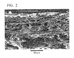
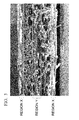
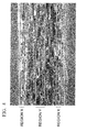
- a cross section polisher based on ion etching or focused ion beam (FIB) device
- common mechanical polishing may easily cause polishing dent or flowing on an interface at which materials are bonded.
- a scanning electron microscope having high depth of field is preferably used.
- the magnification ratio for observing the cross section is preferably magnification ratio for covering the whole at least in the thickness direction (that is, a single photographic image contains from a surface layer at one side to a surface layer at the other side).
- an image analysis software capable of performing binarization of gray scale image and area calculation is preferably used.
- the "state in which no fibers or pores are shown other than the outermost surface" as described in above (ii) indicates that, in the photographic image for observing the surface of the precursor sheet, the area of occupancy by the mixture of the resin (c) and the carbon powder (d) is larger than the area of occupancy by fibers or pores other than the outermost surface. At that time, fibers or pores from other than the outermost surface may be partially seen.
- any method may be employed as long as the carbonization is conducted at temperatures continuously rising from room temperature.
- the carbonization is conducted at 1000°C or higher.
- the carbonization is preferred to be performed under inert atmosphere in a temperature range of 1000°C or higher and 2400°C or lower.
- Prior to the carbonization treatment it is also possible to perform pre-carbonization treatment under inert atmosphere in a temperature range of 300°C or higher but lower than 1000°C. By performing the pre-carbonization treatment, it is easier to completely remove gases generated at an early stage of carbonization, and to suppress decomposed substances from adhering to and depositing onto the inner walls of a carbonization furnace.
- the entire length of precursor sheet is continuously subjected to a heat treatment from the viewpoint of manufacturing costs.
- the productivity of the porous electrode base material increases and also subsequent membrane-electrode assembly (MEA) can also be manufactured continuously, leading to reduced production costs of fuel cells.
- MEA membrane-electrode assembly
- a sheet having an entangled structure in which the short carbon fibers (A) are entangled three dimensionally (entangled-structure sheet) can be formed.
- the precursor fibers (b) are also dispersed along with the carbon fibers (A) in the step [1] for manufacturing the sheet-form product
- a sheet having an entangled-structure in which the short carbon fibers (A) and the precursor fibers (B) are three-dimensionally entangled (entangled-structure sheet) can be formed by performing an entanglement treatment of the sheet-form product.
- the entanglement treatment is not limited to any specific method, and may be selected from those for forming entanglement structures as necessary.
- mechanical entanglement methods such as needle punching, high pressure liquid jetting such as water jet punching, or high pressure gas jetting such as steam-jet punching, or a combination thereof, may be used.
- High pressure liquid jetting is preferred since it is easier to suppress breakage of short carbon fibers (A) during entanglement treatment and to obtain an appropriate entangled structure. The method is described in detail in the following.
- the high pressure liquid jetting is a method in which the sheet-form product is placed on a support member with a substantially smooth surface, and liquid column flow, liquid fan flow, liquid slit flow or the like is injected at a pressure of 1 MPa or greater to entangle the short carbon fibers (A) in the sheet-form product.
- the precursor fibers (b) are also dispersed along with the short carbon fibers (A) in the step [1] for manufacturing a sheet-form product, the short carbon fibers (A) and the precursor fibers (B) are entangled.
- a support member with a substantially smooth surface is selected as desired so that the pattern of the support member will not be transferred onto the entangled body and the injected liquid will be removed promptly. Specific examples include a wire screen, plastic net or roll with a 30 to 200 mesh.
- the sheet-form products containing the short carbon fibers (A) on a support member with a substantially smooth surface, followed by performing continuously the entanglement treatment by high pressure liquid jetting or the like.
- the entanglement treatment of the sheet-form product by high pressure liquid jetting may be repeated multiple times. Namely, it is possible that, after high pressure liquid jetting was performed on the sheet-form product, another sheet-form product is laminated and treated by high pressure liquid jetting. Alternatively, the sheet-form product having an entangled-structure (entangled-structure sheet-form product) may be inverted during the process and high pressure liquid jetting is performed from the opposite side. Such treatment may also be repeated.
- the liquid used for high pressure liquid jetting is not limited specifically as long as it is a medium that does not dissolve the fibers to be treated. Usually, water is preferred. The water may be warm.
- the hole diameter of each high pressure liquid jetting nozzle is preferred to be 0.06 to 1.0 mm, more preferably 0.1 to 0.3 mm, if it makes columnar flow.
- the distance between jetting nozzle holes and the laminate is preferred to be 0.5 to 5 cm.
- the liquid pressure is preferred to be 1 MPa or greater, more preferably 1.5 MPa or greater, from the viewpoint of enough entanglement of the fibers. Entanglement treatment is performed in a single row or multiple rows. When multiple rows are employed, it is more effective to increase the pressure of high pressure liquid jetting to the second and subsequent rows rather than to the first row from the viewpoint of maintaining the shape of the sheet-form product.
- striped patterns caused by uneven fiber density in the sheets may be formed in a lengthwise direction of the sheets.
- a high pressure liquid jetting nozzle with nozzle holes arrayed in a single row or multiple rows is oscillated in a width direction of the sheets, it is easier to suppress such striped patterns.
- striped patterns are suppressed from occurring in a lengthwise direction of the sheets, the tensile strength of the sheets may be exhibited in a width direction.
- the tensile strength of the sheet improves by entanglement treatment, it is not necessary to use a binder, such as polyvinyl alcohol, which is usually added in the sheet forming process. Also, the tensile strength of a sheet can be maintained in water or in a humid situation, allowing continuous addition of the phenolic resin (c) to the entangled-structure sheet. Moreover, since use of the phenolic resin (c) can eliminate the process of collecting an organic solvent, the manufacturing facility is simplified compared with conventional ones, and thus production costs can be reduced.
- a binder such as polyvinyl alcohol
- the precursor sheet is preferred to be heated and compressed at the temperature of 100°C or higher but 250°C or lower.
- the step [5] for heating and compression also has an effect of fusion-bonding the short carbon fibers (A) by the precursor fibers (b).
- the heating and compression method any technique may be employed as long as the precursor sheet is evenly heated and compressed.
- the precursor sheet may be heated and compressed by applying smooth steel plates to both surfaces of the precursor sheet, or using a hot-roll pressing apparatus, a continuous belt pressing apparatus or the like.
- a method using a hot-roll pressing or continuous-belt pressing apparatus is preferred. Accordingly, the step [3] for carbonization described above can be performed continuously.
- the temperature for heating and compression is preferably 100 to 250°C, and more preferably 120 to 230°C to effectively make a smooth surface of the precursor sheet.
- the duration of heating and compression can be 30 seconds to 10 minutes, for example.
- the pressure for heating and compression is not limited specifically.
- the pressure for heating and compression is preferred to be 20 kPa to 10 MPa. If the pressure is 10 MPa or lower, it is easier to prevent breakage in the short carbon fibers (A) during heating and compression, and to provide an appropriate density for the porous electrode base material. If the pressure is 20 kPa or higher, the surface can be easily smoothened.
- the precursor sheet When the precursor sheet is heated and compressed by being sandwiched between two steel plates, or by using a hot-roll pressing or continuous belt pressing apparatus, it is preferred to apply a releasing agent, or to sandwich a releasing paper between the precursor sheet and the steel plate, roller or belt so that fibrous matters do not adhere to the steel plates, roller or belt.
- the manufacturing method of the invention may further include the step [6] for drying the precursor sheet between the step [2] and the step [5]. Including such a step is preferred, since it is easier to reduce the energy for removing a dispersant or unreacted monomers in the step [5].
- the precursor sheet During that time, it is preferred to dry the precursor sheet at the temperature of 20 to 140°C to remove a dispersant or unreacted monomers from the precursor sheet.
- the duration for drying treatment may be from 1 minute to 24 hours, for example.
- the method for drying treatment is not limited specifically, and heat treatment using a hot air furnace or far-infrared furnace, or direct heating treatment using hot plates or hot rollers may be employed.
- heat treatment using a hot air furnace or far-infrared furnace or direct heating treatment using hot plates or hot rollers may be employed.
- the entire length of precursor sheet is preferred to be dried continuously from the viewpoint of reducing production costs. By doing so, the step [5] for heating and compression is performed continuously after the step [6].
- the manufacturing method of the invention may include the step [7] for drying the sheet-form product between the step [1] and the step [2]. Also, when the manufacturing method of the invention includes the step [4], the step [7] for drying the sheet-form product may further be included between the step [1] and the step [4] and/or between the step [4] and the step [2]. When the drying step [7] is performed between the step [4] and the step [2], such drying treatment is conducted on the sheet-form product after entanglement treatment (entangled-structure sheet). Meanwhile, in the invention, the sheet-form product does not include a precursor sheet.
- the sheet-form product is preferred to be dried at 20 to 140°C in any drying step [7] described above.
- the duration for drying treatment is from 1 minute to 24 hours, for example.
- the method for drying treatment it is not limited to any specific method.
- complete dehydration using a dehydration apparatus under reduced pressure can be employed when drying the step [7] is performed between the step [1] and the step [2] or the step [1] and the step [4], for example.
- heating treatment using a hot air furnace or far-infrared furnace, or direct heating treatment using hot plates or hot rollers may be employed.
- drying treatment using a hot air furnace or far-infrared furnace is preferred because fibers from the entangled-structure sheet are prevented from adhering to a heat source.
- the step [7] for drying the sheet-form products can be continuously performed after the step [1] and the step [4].
- moisturized fuel is supplied to maintain suitable proton conductivity by suppressing drying of a polymer electrolyte membrane. Further, as water (water vapor) is generated from the cathode side as an electrode reaction product and condensed as liquid water, which clogs the pores of the porous electrode base material and may interfere gas permeation. As such, to ensure the gas permeability, a water repellent treatment using a water repellent polymer is often carried out.
- water repellent polymer examples include a fluorine-based resin or a silicon resin (silicone) which is chemically stable and has high water repellency.
- silicone has low acid resistance, it cannot be contacted with a polymer electrolyte membrane which is strongly acidic. As such, only the fluorine-based resin is used.
- Fluorine-based resin is not particularly limited, but homopolymers or copolymers of fluorine-based monomers, such as tetrafluoroethylene (TFE), hexafluoropropylene (HFP), vinylidene fluoride (VDF), chlorotrifluoroethylene (CTFE), vinyl fluoride, perfluoroalkyl vinyl ether, perfluoro(allyl vinyl ether), perfluoro(butenyl vinyl ether) (PBVE), or perfluoro(2,2-dimethyl-1,3-dioxole) (PDD), can be used.
- fluorine-based monomers such as tetrafluoroethylene (TFE), hexafluoropropylene (HFP), vinylidene fluoride (VDF), chlorotrifluoroethylene (CTFE), vinyl fluoride, perfluoroalkyl vinyl ether, perfluoro(allyl vinyl ether), perfluoro(butenyl vinyl ether) (
- an ethylene-tetrafluoroethylene copolymer ETFE
- an ethylene-chlorotrifluoroethylene copolymer ECTFE
- These fluorine-based resins are preferably in a state of being dissolved in a solvent or being dispersed as a granular form in a dispersion medium, such as water or alcohol, from the viewpoint of impregnation property.
- PTFE polytetrafluoroethylene
- FEP tetrafluoroethylene-hexafluoropropylene copolymer
- PFA tetrafluoroethylene-perfluoroalkyl vinyl ether
- PVDF polyvinylidene fluoride
- an impregnation method by which the porous electrode base material is impregnated in a dispersion in which fine particles of a fluorine-based resin are dispersed and a spray method for spraying a dispersion
- concentration of the fluorine-based resin dispersion is not particularly limited. However, in order to avoid clogging of the pores of the porous electrode base material and evenly adhere with the fluorine-based resin, it is preferably 1 to 30% by weight or so in terms of solid matter. It is more preferably 10 to 30% by weight, and particularly preferably 15 to 25% by weight.
- the calcination temperature should be within a temperature region in which PTFE is softened and binds to the short carbon fibers (A), the carbon powder (d), or the resin carbide (C) but it does not thermally decomposed. It is more preferably 300 to 390°C, and particularly preferably 320 to 360°C.
- the fluorine-based resin is applied such that it can coat from the outside the macroscopic conduction path in the porous electrode base material in which the short carbon fibers (A) and the carbon powder (d) are bound by the resin carbide (C).
- the fluorine-based resin is present on the surface of the conduction path.
- most of the fluorine-based resin aggregate near the cross-point among fibers, and surface of the short carbon fibers (A), the carbon powder (d), or the resin carbide (C), which constitute the porous electrode base material is not coated with the fluorine-based resin having no gap.
- the conduction path which extends from the surface of a base to the inside of a base is secured and both the water repellency and conductivity can be obtained.
- the number of adding the fluorine-based resin is not particularly limited, a small addition number is preferred from the viewpoint of reducing the production cost.
- the slurry of the fluorine-based resin to be added may be the same, or slurries with different slurry concentration or different type of the fluorine-based resin may be used.
- the addition amount of the fluorine-based resin may be constant in the thickness direction of the porous electrode base material or it may have a concentration gradient.
- the short carbon fibers (A) as a kind of fiber constituting the porous electrode base material may be entangled in the thickness direction in the sheet-form product, the precursor sheet, and the porous electrode base material.
- Examples of the short carbon fibers (A) include those obtained by cutting carbon fibers, such as polyacrylonitrile-based carbon fibers (hereinafter referred to as "PAN-based carbon fibers"), pitch-based carbon fibers, and rayon-based carbon fibers, to a suitable length. Taking into consideration the mechanical strength of the porous electrode base material, PAN-based carbon fibers are preferred.
- the average fiber length of the short carbon fibers (A) is preferred to be 2 to 12 mm considering dispersibility.
- the average diameter of the short carbon fibers (A) is preferred to be 3 to 9 ⁇ m considering production costs and dispersibility of short carbon fibers. It is more preferably 4 to 8 ⁇ m considering smoothness of the porous electrode base material.
- the average fiber lengths are measured using a commercially available fiber length measuring instrument (for example, HiRes-FQA (trade name), manufactured by Nomura Shoji Co., Ltd.), and an average fiber diameter is measured using a commercially available fiber diameter measuring instrument (for example, FDAS 765 (trade name), manufactured by Dia-Stron Ltd.).
- the carbon fiber precursor short fibers (b1) and/or the fibrillar fibers (b2) are used as the precursor fibers (b) in the invention.
- the carbon fiber precursor short fibers (b1) may be formed by cutting carbon fiber precursor long fibers into appropriate lengths.
- Carbon fiber precursor fibers in long fiber form may be made from the later-described polymers (acrylic polymers, for example).
- the average fiber length of the carbon fiber precursor short fibers (b1) is preferred to be 2 to 20 mm from the viewpoint of dispersibility.
- the cross-sectional shape of the carbon fiber precursor short fibers (b1) is not limited specifically, but a shape closer to a perfect circle is preferred considering production costs and mechanical strength after carbonization.
- the average fiber diameter of the carbon fiber precursor short fibers (b1) is preferred to be 5 ⁇ m or less to easily suppress breakage due to contraction during the heating and compression step [5] and the carbonization step [3]. Also, considering spinnability, the average fiber diameter of the carbon fiber precursor short fibers (b1) is preferred to be 1 ⁇ m or greater.
- the remaining mass after the carbonization step is preferred to be 20% by mass or greater to maintain the sheet shape after carbonization.
- the polymers include acrylic polymers, cellulose-based polymers and phenolic polymers.
- Acrylic polymers used for the carbon fiber precursor short fibers (b1) may be homopolymers of acrylonitrile or copolymers of acrylonitrile and another monomer.
- monomers to be copolymerized with acrylonitrile they are not limited specifically as long as they are unsaturated monomers constituting general acrylic fibers; for example, acrylic acid esters represented by methyl acrylate, ethyl acrylate, isopropyl acrylate, n-butyl acrylate, 2-ethylhexyl acrylate, 2-hydroxyethyl acrylate, and hydroxypropyl acrylate; methacrylic acid esters represented by methyl methacrylate, ethyl methacrylate, isopropyl methacrylate, n-butyl methacrylate, isobutyl methacrylate, t-butyl methacrylate, n-hexyl methacrylate, cyclohexyl methacrylate, lauryl me
- the weight average molecular weight of an acrylonitrile-based polymer used for the short carbon precursor (b1) is not limited specifically, but it is preferred to be 50,000 to 1,000,000. When the weight average molecular weight is 50,000 or more, fiber spinnability is enhanced, and the yarn quality of fibers tends to be better. When the weight average molecular weight is 1,000,000 or less, the polymer density providing an optimum viscosity for a spinning stock solution is higher, and thus the productivity tends to improve.
- the carbon fiber precursor short fibers (b1) it is possible to use one type, or to use two or more types of the carbon fiber precursor short fibers (b1) with different fiber diameters and containing different polymers.
- the remaining amount of the carbon fibers (B) derived from the precursor fibers (b) can be adjusted in a porous electrode precursor obtained in the end.
- the ratio for combining the short carbon fibers (A) and the precursor fibers (b) is preferred to be determined such that the short carbon fibers (A) and the precursor fibers (B) after carbonization in a porous electrode base material have the following ratios.
- the amount of the carbon fibers (B) in a porous electrode base material is preferred to be 1% by mass or greater, from the viewpoint of the binding effect on the short carbon fibers (A); and 50% by mass or lower, from the viewpoint of the mechanical strength of the porous electrode base material.
- the amount of the carbon fibers (B) in the porous electrode base material is more preferred to be 4 to 25% by mass with respect to the sum of the short carbon fibers (A) and the carbon fibers (B).
- the fibrillar fibers (b2) are dispersed with the short carbon fibers (A) and prevent the short carbon fibers (A) from converging again, while setting a sheet-form product to be an independent sheet. Also, depending on the resin to be used (phenolic resin (c), for example), condensation water may be produced when the resin cures. It is also expected that fibrillar fibers can absorb and discharge such water. Thus, it is preferred to use a resin with hydrophilic properties. Examples of the specific fibrillar fibers (b2) include synthetic pulp such as fibrillar polyethylene fibers, acrylic fibers and aramid fibers. The fibrillar fibers (b2) may be those having residual carbon (remain as carbon) after carbonization treatment, or those not having residual carbon (do not remain as carbon) after carbonization treatment.
- the fibrillar fibers (b2) may be the carbon fiber precursor fibers (b2-1) which have a structure in which numerous fibrils with a diameter of a few ⁇ m or less (0.1 to 3 ⁇ m, for example) branch out from fibrous stems, or the carbon fiber precursor short fibers (b2-2) which are fibrillated by beating splittable sea-island composite fibers.
- the short carbon fibers (A) and the fibrillar fibers (b2) entangle well in a precursor sheet, thereby making it easier to obtain a precursor sheet with excellent mechanical strength.
- the freeness of the fibrillar fibers (b2) is not limited specifically.
- the fibrillar fibers (b2) it is possible to use one type of the fibers (b2-1), or two or more types of the fibers (b2-1) with different freeness degrees and fiber diameters or containing different polymers. Also, the fibrillar fibers (b2) may be used in the form of one type of the fibers (b2-2), or two or more types of the fibers (b2-2) with different freeness degrees and fiber diameters or containing different polymers, or any combination of the above can be also used.
- the remaining mass amount in the carbonization step is preferred to be 20% by mass or greater from the viewpoint of forming a structure of a porous electrode base material together with the short carbon fibers (A) after carbonization.
- polymers include acrylic polymers, cellulose-based polymers and phenolic polymers.
- the acrylic polymers used for the fibers (b2-1) may be the same acrylic polymers used for the carbon fiber precursor short fibers (b1) described above. Among those, acrylic polymers containing 50% by mass or greater of acrylonitrile units are preferred, considering spinnability, capability of binding the short carbon fibers (A) in a temperature range from low to high, a greater remaining mass amount in heating and compression and carbonization treatments, entanglement with the short carbon fibers (A), and sheet strength.
- the method for manufacturing the fibers (b2-1) is not limited specifically, but an injection-coagulation method is preferred since it is easier to control freeness.
- the average fiber length of the fibers (b2-1) is preferred to be 0.1 mm or greater considering maintenance of the mechanical strength of a porous electrode base material, and 3 mm or less considering dispersibility in a precursor sheet. Also, the diameter (average fiber diameter) of the fibers (b2-1) is preferred to be 0.01 ⁇ m or greater, from the viewpoint of ensuring the dehydration property when manufacturing a precursor sheet or gas permeability of the porous electrode base material, and 30 ⁇ m or smaller considering suppression of breakage caused by contraction during heat treatment.
- the fibers (b2-2) may be long splittable sea-island composite fibers cut into appropriate lengths and fibrillated by beating using a refiner or pulper.
- the splittable sea-island composite fibers are fibrillated by beating.
- the long splittable sea-island composite fibers can be produced by using two or more types of polymers which dissolve in a common solvent but are incompatible with each other. At that time, at least one of the polymers is preferred to have a remaining amount of 20% by mass or greater in a carbonization the step from the viewpoint of having the structure of the porous electrode base material together with the short carbon fibers (A) after carbonization.
- acrylic polymers, cellulose-based polymers and phenolic polymers for example, can be mentioned as those having a remaining amount of 20% by mass or greater in the carbonization step.
- Acrylic polymers used for the splittable sea-island composite fibers may be the same acrylic polymers used for the carbon fiber precursor short fibers (b1) described above. Among those, acrylic polymers containing 50% by mass or greater of acrylonitrile units are preferably used from the viewpoint of spinnability and the remaining mass amount in the carbonization treatment step.
- the weight average molecular weight of an acrylonitrile-based polymer used for splittable sea-island composite fibers is not limited specifically, but it is preferred to be 50,000 to 1,000,000. When the weight average molecular weight is 50,000 or more, spinnability improves, and the yarn quality of fibers tends to be better. When the weight average molecular weight is 1,000,000 or less, the polymer density providing an optimum viscosity for a spinning stock solution is higher, and thus the productivity tends to improve.
- a splittable sea-island composite fiber when an acrylic polymer described above is used for one of the polymers whose remaining mass amount is 20% by mass or greater in the step for carbonization treatment [3], another polymer is required to be dissolved in a common solvent with the acrylic polymer and to stay stable in a spinning stock solution. Namely, the other polymer is required to be incompatible with the acrylonitrile-based polymer when dissolved in a common solvent with the acrylonitrile-based polymer, but to have compatibility to such a degree that it can form a sea-island structure in a spinning the step.
- the other polymer that satisfies the above requirements, the following, for example, may be listed: polyvinyl chloride, polyvinylidene chloride, polyvinylidene fluoride, polyvinylpyrrolidone, cellulose acetate, an acrylic resin, a methacrylic resin, a phenolic resin and the like. Among those, cellulose acetate, an acrylic resin, and a methacrylic resin are preferable in terms of balancing the above requirements.
- the other polymer may be one type or a combination of two or more types of polymers.
- Splittable sea-island composite fibers used for the fibers (b2-2) may be produced using a regular wet spinning method.
- one of the polymers is an acrylonitrile-based polymer whose remaining mass amount is 20% by mass or greater in the step [3]
- splittable sea-island composite fibers can be produced by the following method. First, the acrylonitrile-based polymer and the other polymer are mixed and then dissolved in a solvent to form a spinning stock solution of splittable sea-island composite fibers.
- a spinning stock solution obtained by dissolving an acrylonitrile-based polymer in a solvent and another spinning stock solution obtained by dissolving the other polymer in a solvent may be mixed by a static mixer or the like to give a spinning stock solution of splittable sea-island composite fibers.
- An organic solvent such as dimethylamide, dimethyl formamide, dimethyl sulfoxide or the like can be used for the solvent.
- Splittable sea-island composite fibers can be obtained by spinning those spinning stock solutions through a nozzle, and conducting hot wet stretching, cleansing, drying, and hot dry stretching.
- the cross-sectional shape of splittable sea-island composite fibers is not limited specifically.
- the fineness of splittable sea-island composite fibers is preferred to be 1 to 10 dtex.
- the average fiber length of splittable sea-island composite fibers is preferred to be 1 to 20 mm from the viewpoint of dispersibility.
- the splittable sea-island composite fibers are beaten as a result of interfacial peeling which is caused by external mechanical force, and at least some of the fibers are split to become fibrillated.
- a beating method is not limited to any specific method; for example, a refiner, pulper, beater, or high pressure water jetting (water jet punching) may be used to fibrillate fibers.
- the fibrillated state may vary depending on the method and duration of beating.
- the degree of fibrillation can be evaluated based on its freeness.
- the freeness is obtained according to P8121 (pulp freeness testing: Canadian standard) using a Canadian Standard Freeness (CSF) tester.
- P8121 pulse freeness testing: Canadian standard
- CSF Canadian Standard Freeness
- the freeness of splittable sea-island composite fibers is not limited specifically; however, the smaller the freeness, the more likely it is that the carbon fibers (B) with a three-dimensional cross-linked structure are formed. When splittable sea-island composite fibers having high freeness are used directly without conducting sufficient beating, the carbon fibers (B) with a fiber structure are more likely to be formed.
- the average fiber length of the fibers (b2-2) is preferred to be 1 mm or greater Considering maintenance of the mechanical strength of a precursor sheet, and more preferably 20 mm or less considering dispersibility. Also, the average fiber diameter of the fibers (b2-2) is preferred to be 1 ⁇ m or greater considering enhancement of dispersibility, and preferably 50 ⁇ m or less considering suppression of breakage caused by contraction during the heat treatment. Moreover, the average fiber diameter of fibrillated portions of the fibers (b2-2) is preferred to be 0.01 ⁇ m or greater considering dehydration property when forming a precursor sheet or maintenance of gas permeability of a porous electrode base material. It is also preferred to be 30 ⁇ m or less considering enhancement of the dispersibility.
- the carbon fibers (B) are carbon fibers that are obtained by the carbonizing treatment, among the carbon fiber precursor short fibers (b1) and the fibrillar fibers (b2), those having residual carbon (remain as carbon).
- the carbon fiber precursor short fibers (b1) can be those obtained by cutting long fibrillar carbon fiber precursor fibers to a suitable length.
- the average fiber diameter of the carbon fibers (B) is preferably 5 ⁇ m or less from the viewpoint of forming pores that are suitable for gas permeability or moisture management (moisturizing property or water draining property). Further, from the viewpoint of mechanical strength, the average fiber diameter of the carbon fibers (B) is preferably 0.1 ⁇ m or more. More preferably, it is 0.5 ⁇ m to 3 ⁇ m.
- a water soluble phenolic resin and/or a water dispersible phenolic resin are used as the phenolic resin (c) in the invention.
- water dispersible phenolic resins used in the invention for example, an emulsified solution (emulsion) or a suspension solution (suspension) of the phenolic resins described in JP 2004-307815 A , JP 2006-56960 A , and the like, or well-known water dispersible phenolic resins which is also referred to as an aqueous dispersion can be used.
- a resol type phenolic resin before cross-linking is mostly present as liquid within a temperature and pressure range in which water is present as liquid, and thus the aqueous dispersion is often present as an emulsified solution (emulsion).
- a Novolac type phenolic resin generally has a higher molecular weight compared to a resol type phenolic resin and is mostly present as solid within a temperature and pressure range in which water is present as liquid, and thus the aqueous dispersion is often present as a suspension solution (suspension).
- the average particle diameter of the phenolic resin is preferably 10 ⁇ m or less, and more preferably 5 ⁇ m or less from the viewpoint of infiltrating into an inner layer of the sheet-form product.
- phenolic resin powder which is obtained by crushing after bulk polymerization and not intended to be dispersed in water, is dispersed in water by force, it is not expected to have quantitative infiltration into an inner layer of the sheet-form product, and therefore undesirable.
- Specific examples thereof include trade names: Phenolite TD-4304 and PE-602, manufactured by DIC Corporation, trade names: Sumilite Resin PR-14170, PR-55464 and PR-50607B, manufactured by Sumitomo Bakelite Co., Ltd., trade name Shonol BRE-174, manufactured by Showa Denko K.K., or the like.
- the water dispersible phenolic resin tends to easily bind to the short carbon fibers (A) and remain as a conductive substance when it is carbonized, the same as regular phenolic resins that use methanol, methyl ethyl ketone or the like as a solvent.
- water dispersible phenolic resins With regard to the form of obtainable water dispersible phenolic resins, it is preferred to use commercially available aqueous dispersion types or granular types from the viewpoint of handling and production costs.
- aqueous dispersion types or granular types By using commercially available water dispersible phenolic resins, residues of organic solvents or unreacted monomers that remain during the production process are less than those of regular phenolic resins. Namely, since amounts of organic solvents or unreacted monomers that volatilize during drying or heating and compression treatment are small, the production cost can be saved as discharge facilities or the like are simplified.
- Water soluble phenolic resins used in the invention are, for example, well-known water soluble phenolic resins such as resol type phenolic resins with excellent solubility described in JP 2009-84382 A , for example; more specifically, trade name Resitop PL-5634, manufactured by Gun Ei Chemical Industry Co., Ltd., trade names Sumilite Resin PR-50781, PR-9800D and PR-55386, manufactured by Sumitomo Bakelite Co., Ltd., trade name Shonole BRL-1583 and BRL-120Z, manufactured by Showa Denko K.K., or the like.
- the water soluble phenolic resin easily binds to the short carbon fibers (A) and easily remains as a conductive substance when it is carbonized, the same as regular phenolic resins that use methanol or methyl ethyl ketone as a solvent.
- water soluble phenolic resins With regard to the form of obtainable water soluble phenolic resins, it is preferred to use commercially available aqueous solution types from the viewpoint of handling and production costs.
- aqueous solution types By using commercially available water soluble phenolic resins, residues of organic solvents or unreacted monomers that remain during the production process are less than those of regular phenolic resins. Namely, since amounts of organic solvents or unreacted monomers that volatilize during drying or heating and compression treatment are small, the production cost can be saved as discharge facilities or the like are simplified.
- the phenolic resin (c) used in the above-described step [2] for adding resin is preferred to be a dispersion (emulsified solution or suspension solution) or aqueous solution type from the viewpoint of infiltration into a sheet.
- the solid matter concentration of the phenolic resin (c) in a dispersion or an aqueous solution is preferred to be 1% by mass or greater for exhibition of the strength and conductivity of the porous electrode base material, and 40% by mass or less to make a low-viscosity dispersion with a high infiltration property. It is more preferably 5 to 35% by mass.
- the phenolic resin (c) As a medium to dilute or disperse the obtained the phenolic resin (c), water, alcohol or a combination thereof is preferred considering handling and production costs. In addition, it is more preferred to consist primarily of water considering production costs, atmospheric environmental protection and human environmental protection.
- the resin carbide (C) indicates an amorphous substance that is obtained by carbonization of a carbon precursor resin, which binds, either by itself or with the resin carbide (C) and the carbon fibers (B), the short carbon fibers (A) to each other or with the carbon powder (d).
- the carbon precursor resin those having high binding property to carbon fibers such as phenolic resin and high residual mass at the time of carbonization are preferable, but the carbon precursor resin is not specifically limited thereto.
- a ratio of the resin carbide (C) finally remained as a carbide in a porous carbon electrode base material varies.
- the resin carbide (C) is preferably 5 to 25% by mass therein. More preferred lower limit and upper limit are 10% by mass and 20% by mass, respectively.
- the resin carbide (C) derived from at least one selected from a group consisting of a water soluble phenolic resin and a water dispersible phenolic resin is included.
- the carbon powder (d) using graphite powder, carbon black, milled fiber, or a mixture thereof is preferable from the viewpoint of exhibiting conductivity.
- Graphite powder is composed of a highly crystalline graphite structure and the average particle diameter of its primary particles is generally several micrometers to several hundred micrometers.
- the resin (c) penetrates in the thickness direction of the sheet-form product and infiltrates to its backside.
- graphite powder hardly infiltrates in the thickness direction so that it may be localized in the vicinity of the surface layer.
- Examples of the graphite powder which can be used include pyrolytic graphite, spherical graphite, flake graphite, chunky graphite, earthy graphite, artificial graphite, expanded graphite, or the like. However, from the viewpoint of exhibiting conductivity, pyrolytic graphite, spherical graphite, or flake graphite is preferable.
- Carbon black is generally present as structures (agglomerates) in which primary particles having an average particle diameter of several tens of nanometers are joined together by melting to form structures, and further, the structures are joined together by Van der Waals force. Carbon black has a significantly larger number of particles per unit mass than graphite powder, and at a certain critical concentration or more, the agglomerates are connected like a three-dimensional network to form macroscopic conductive paths.
- the addition solution containing carbon black mixed at critical concentration or more with the resin (c) in liquid phase is added to the sheet-form product, the resin (c) penetrates in the thickness direction of the sheet-form product and infiltrates to its backside.
- carbon black hardly infiltrates in the thickness direction so that it can be localized in the vicinity of the surface layer.
- Furnace black, channel black, acetylene black, lamp black, thermal black, ketjen black, or the like can be used as the carbon black.
- Acetylene black or ketjen black having excellent electrical conductivity is more preferred.
- milled fiber those produced by crushing virgin carbon fibers can be used or those produced from recycled product such as a molded article of carbon fiber-reinforced thermosetting resin, a molded article of carbon fiber-reinforced thermoplastic resin, or a prepreg can be also used.
- the phenolic resin (c) and the carbon powder (d) are preferably in a slurry phase.
- the dispersion solvent from the viewpoint of handling property and production cost, it is preferable to use water, alcohol, dimethyl formamide, dimethyl acetamide, or a mixture thereof.
- a dispersant like surfactant may be used for dispersing the phenolic resin (c) or the carbon powder (d).
- the dispersant which can be used include polyethers such as polyoxyethylene alkylphenyl ether and aromatic sulfonates such as naphthalene sulfonate.
- a dispersant containing a metal ion such as sodium may damage the furnace as it remains in the precursor sheet and gets scattered in the furnace during the following carbonation step, and thus its use is preferably avoided.
- the mass ratio of the carbon powder (d) relative to the solid matter of the phenolic resin (c) varies depending on particle size distribution or viscosity of the phenolic resin (c) or particle size distribution, volume size, or easiness of agglomeration of the carbon powder (d). However, from the viewpoint of exhibiting conductivity or handling property, it is preferably 0.001 to 3.0, more preferably 0.01 to 2.0, and particularly preferably 0.1 to 1.0. When the ratio is excessively low, sufficient conductivity is not obtained or carbon powder is not localized on the surface as it penetrates through the backside.
- the viscosity of the dispersion (e) is excessively high even with a combination of the phenolic resin (c) and the carbon powder (d) so that components of the phenolic resin (c) also cannot penetrate the sheet-form product.
- the average particle diameter of the substantial particles or agglomerate of the carbon powder (d) is, from the viewpoint of holding and having surface localization of the sheet-form product which consists of the short carbon fibers (A) and at least one selected from a group of the precursor fibers (b), preferably 0.1 to 50 ⁇ m or so, and more preferably 1 to 20 ⁇ m.
- the aforementioned "substantial particles” indicate particles that are stably present in the dispersion (e) of the resin (c) and the carbon powder (d) under an environment which is free from strong shearing to disrupt the agglomerate.
- graphite powder or miller fiber it corresponds to the primary particles.
- carbon black it corresponds to structures or agglomerates in which the primary particles are agglomerated.
- the porous electrode base materials may have a shape like a flat sheet, a whirlpool, or the like.
- the weight of the sheet-type porous electrode base material per unit area is preferred to be 15 g/m 2 or more but 100 g/m 2 or less considering handling property.
- the porosity of a sheet-type porous electrode base material is preferred to be 50% or greater considering gas diffusion property, but 90% or less considering its mechanical strength.
- the thickness of the sheet-type porous electrode base material is preferred to be 50 ⁇ m or greater but 300 ⁇ m or less considering handling property.
- the undulation of the sheet-type porous electrode base material is preferably 5 mm or less from the viewpoint of performing uniform post treatments such as water repellent treatment.
- the gas permeability of the porous electrode base material is preferably 10 mL/hr/cm 2 /Pa or greater considering gas diffusion property, and also preferably 3000 mL/hr/cm 2 /Pa or less from the viewpoint of preventing drying of the electrolyte membrane.
- electrical resistance in a thickness direction (through-plane resistance) of the porous electrode base material is preferred to be 50 m ⁇ cm 2 or less from the viewpoint of collecting efficiently electrons that are generated at electrode catalysts. Methods for measuring gas permeability and through-plane resistance of the porous electrode substance are described later in Examples.
- the expression "the carbon powder (d) is localized in the vicinity of the surface layer of a single side or both sides of the sheet-form structure” means that, compared to the inside (inner layer) of the porous electrode base material, the carbon powder (d) is present more on a surface, or on a surface and in the vicinity of a surface layer of the porous electrode base material.
- the “surface” indicates a surface which can be observed without performing a special processing like cutting or polishing.
- "in the vicinity of the surface layer” indicates a region with a certain width in the thickness direction, including the surface.
- the "pore occupancy in the vicinity of the surface layer is relatively low, and thus it is difficult to identify each fiber, but the pore occupancy is relatively high in the inner layer, and thus it has a state which allows easy identification of each fiber" in the above (i) can be determined from a photographic image for observing cross section.
- the pore occupancy in the region X when the region from the outermost layer of the porous electrode base material to the depth of 20 ⁇ m is X and the region from the center of the porous electrode base material to the depth of 40 ⁇ m in the thickness direction is Y, it is preferable that the pore occupancy in the region X be less than 30% and the pore occupancy in the region Y be 50 to 90%, and it is more preferable that the pore occupancy in the region X be less than 25% and the pore occupancy in the region Y be 60 to 80%. Meanwhile, the "pore occupancy” indicates the value that is obtained by the calculation method to be described below.
- a cross section polisher based on ion etching or focused ion beam (FIB) device
- common mechanical polishing may easily cause polishing dent or flowing on an interface at which materials are bonded.
- a cross section polisher based on ion etching or focused ion beam (FIB) device
- common mechanical polishing may easily cause polishing dent or flowing on an interface at which materials are bonded.
- the observation of the cross section or surface of the porous electrode base material it is not particularly limited if it is a method allowing easy identification of fibers or particles. However, a scanning electron microscope having a high depth of field is preferably used.
- the magnification ratio for observing the cross section is the magnification ratio for covering the whole at least in the thickness direction (that is, a single photographic image contains from a surface layer at one side to a surface layer at the other side).
- magnification ratio is 200 times to 500 times or so.
- an image analysis software for binarization of gray scale image to fractionate a pore part and the remaining part and area calculation of each part is preferably used.
- the "state in which no fibers or pores are shown other than the outermost surface" as described in the above (ii) indicates that, in the photographic image for observing the surface of the porous electrode base material, the area of occupancy by the mixture of the resin carbide (C) and the carbon powder (d) is larger than the area of occupancy by fibers or pores other than the outermost surface. At that time, fibers or pores from other than the outermost surface may be partially seen.
- the area of occupancy by the mixture of the resin carbide (C) and the carbon powder (d) is preferably 50% or more, more preferably 70% or more, and particularly preferably 90% or more of the total in a photographic image for surface observation.
- a region having the short carbon fibers (A) and the carbon powder (d) bound by the resin carbide (C) is localized in the vicinity of the surface layer of a single side or both sides of the structure.
- the porous electrode base material of the invention Since being produced by the manufacturing method described above, the porous electrode base material of the invention has following characteristics.
- the bulk density of the porous electrode base material is calculated as follows from the weight of the porous electrode base material per unit area and the initial thickness of the porous electrode base material to be described later in detail.
- Bulk density g / cm 3 Weight per unit area g / cm 2 / Initial thickness ⁇ m
- the bulk density is 0.20 g/cm 3 or greater, a porous electrode base material is formed, which is low in through-plane resistance as being easy to handle. If the bulk density is 0.45 g/cm 3 or less, a porous electrode base material with excellent gas permeability is obtained. Also, considering mechanical strength and cushion characteristics, the bulk density is preferred to be 0.25 g/cm 3 or greater but 0.45 g/cm 3 or less.
- whether or not the short carbon fibers (A) form a three-dimensional entangled structure is determined by observing a cross section of a sheet-form product as a measurement subject (porous electrode base material) and by measuring the angle between the short carbon fibers (A) and a sheet surface at the cross section.
- the cross section to be observed is positioned perpendicular to a sheet surface of the sheet-form product as a measurement subject.
- a SEM (scanning electron microscope) photograph is taken at a cross section in a direction perpendicular to the sheet surface, and the short carbon fibers (A) to be measured are connected with a line (dotted line shown in Fig. 2 ) so that the angle between the line and the sheet surface may be measured.
- the number of spots to measure for calculating the average angle may be 50, for example.
- Line 1 in Fig. 2 is parallel to the sheet surface.
- MCA Membrane-electrode assembly
- solid polymer type fuel cell
- porous electrode base material of the invention can be suitably used for membrane-electrode assemblies of solid electrolyte fuel cells. Also, membrane-electrode assemblies using the porous electrode base materials of the invention can be preferably used for solid electrolyte fuel cells.
- a precursor sheet is produced at the step before the step [3] for carbonization treatment.
- Examples thereof include the following [1] to [6].
- the phenolic resin (c) is preferably at least one phenolic resin (c) selected from a group consisting of a water soluble phenolic resin and a water dispersible phenolic resin.
- the expression “the carbon powder (d) is localized in the vicinity of the surface layer of a single side or both sides of the sheet-form structure” means that, compared to the inside (inner layer) of the precursor sheet, the carbon powder (d) is present more on a surface, or on a surface and in the vicinity of a surface layer of the precursor sheet.
- the "surface” indicates a surface which can be observed without performing a special processing like cutting or polishing.
- "in the vicinity of the surface layer” indicates a region with a certain width in the thickness direction, including the surface.
- the pore occupancy is relatively high in the inner layer, and thus it has a state which allows easy identification of each fiber.
- the pore occupancy in the vicinity of the surface layer are filled with the carbon powder (d) so that the pore occupancy is relatively low, and thus it is difficult to identify each fiber.
- the pore occupancy is relatively high in the inner layer, and thus it has a state which allows easy identification of each fiber.
- a region having the short carbon fibers (A) and the carbon powder (d) bound by the phenolic resin (c) is localized in the vicinity of the surface layer of a single side or both sides of the sheet-form structure" described in the above [2] and [5] indicates, in addition to the aforementioned (i) and (ii), (iii) a state in which the shape of the particles derived from the carbon powder (d) can be identified from a photographic image for observing the surface of the precursor sheet.
- the thickness of the porous electrode base material was measured as follows using a micro sample pressure testing instrument Micro Autograph (trade name: MST-I, manufactured by Shimadzu Corporation). First, the parallel degree between a 50 mm-diameter upper platen (fixed type) and a 50 mm-diameter lower platen (ball-bearing type) was adjusted, nothing was sandwiched therebetween, and then a load rod was lowered at a stroke speed of 0.4 mm/min. When the pressure of 3 MPa was applied, the stroke of the load rod was immediately stopped, and the values at three displacement gauges between platens were each set at zero.
- a 25 mm diameter test piece (porous electrode base material) was placed between the upper and lower platens and the load rod was lowered at a stroke speed of 0.4 mm/min.
- a pressure of 0.05 MPa was applied on the test piece, the stroke of the load rod was immediately stopped, and 30 seconds later, the values at three displacement gauges between the platens were read, and their average value was determined as the thickness.
- the porosity in the region X or region Y was measured as follows.
- the scanning electron microscopic image of the cross section obtained at a magnification ratio of 300 was subjected to the image analysis software (ImagePro), and according to binarization, it was fractionated into a pore part and the remaining part and the area ratio of the pore part in the whole region was calculated.
- the short carbon fibers (A) PAN-based carbon fibers with an average fiber diameter of 7 ⁇ m and an average fiber length of 3 mm were prepared.
- the carbon fiber precursor short fibers (b1) short acrylic fibers with an average fiber diameter of 4 ⁇ m and an average fiber length of 3 mm were prepared (trade name D122, manufactured by Mitsubishi Rayon Co., Ltd.).
- the fibrillar fibers (b2) prepared was polyacrylonitrile-based pulp (b2-1) having numerous fibrils with a diameter of 3 ⁇ m or less branched out from fibrous stems formed by injection-coagulation.
- a sheet-form product and a three-dimensionally entangled-structure sheet formed by entanglement treatment were produced by the following wet continuous sheet forming method and by an entanglement treatment method using continuous jetting treatment of pressurized water.
- PAN-based carbon fibers with an average fiber diameter of 7 ⁇ m and an average fiber length of 3 mm were dispersed in water to have a fiber concentration of 1% (10 g/L), and put through a disc refiner (manufactured by Kumagai Riki Kogyo Co., Ltd.) for disaggregation treatment. Accordingly, disaggregated fiber slurry (SA) was obtained.
- SA disaggregated fiber slurry
- short acrylic fibers with an average fiber diameter of 4 ⁇ m and an average fiber length of 3 mm (trade name: D122, manufactured by Mitsubishi Rayon Co., Ltd.) were dispersed in water to have a fiber concentration of 1% (10 g/L). Accordingly, disaggregated fiber slurry (Sb1) was obtained.
- fibrillar fibers (b2) polyacrylonitrile-based pulp having numerous fibrils with a diameter of 3 ⁇ m or less branched out from fibrous stems formed by injection-coagulation were dispersed in water to have a fiber concentration of 1% (10 g/L). Accordingly, disaggregated fiber slurry (Sb2) was obtained.
- the disaggregated fiber slurry (SA), the disaggregated fiber slurry (Sb1) and the disaggregated fiber slurry (Sb2) and a diluent were measured and put into a slurry supply tank, with a mass ratio of short carbon fibers (A) to carbon fiber precursor short fibers (b1) and to fibrillar fibers (b2) at 60 : 20 : 20, and with a fiber concentration in slurry (hereinafter referred to as flock) at 1.7 g/L. Furthermore, polyacrylamide was added to prepare slurry for making a sheet with a viscosity of 22 centipoise.
- the apparatus is constituted as follows: a sheet-form product conveyor equipped with a belt formed by connecting 60 cm wide x 585 cm long plastic nets of plain mesh and a net driver to rotate the net continuously; a sheet forming slurry supply apparatus with a slurry supply width of 48 cm and a slurry supply amount of 30 L/min; a reduced-pressure dehydration apparatus positioned under the net; and a pressurized water jetting treatment apparatus to be described below.
- Three nozzles of two different types as shown in Table 1 were used as water jet nozzles.
- the above sheet forming slurry was supplied using a metering pump.
- the flow of sheet forming slurry was widened to a predetermined size by going through a flow box for setting a uniform flow.
- the slurry was put through a section for settling and natural dehydration, and the slurry was completely dewatered using a dehydration apparatus under reduced pressure.
- wet web with a target weight per unit area of 65 g/m 2 was loaded on the net (steps [1] and [7]).
- the sheet-form product was put under water jet nozzles positioned in the back of the test instrument so that pressurized water jetting pressures at 3 MPa (nozzle 1), 3 MPa (nozzle 2) and 4 MPa (nozzle 3) in that order were exerted for entanglement treatment (step [4]).
- an aqueous dispersion of two kinds of resol type phenolic resin (trade names PR-14170 and PR-55464, manufactured by Sumitomo Bakelite Co., Ltd.) was prepared, which was then diluted with pure water to have resin to solid matter ratio of 7 : 3 and the total resin solid content of 10% by mass of the aqueous resin dispersion.
- pyrolytic graphite (trade name: PC-H, manufactured by Ito Kokuen Co., Ltd.) was added as the carbon powder (d) such that the ratio of carbon powder/resin solid matter is 1.0, to yield an addition solution.
- the precursor sheet was continuously heated and compressed using a continuous heating and compression apparatus equipped with a pair of endless belts disclosed in JP 3699447 B1 (double belt press apparatus: DBP) (step [5]), for example, and an intermediate base material with flattened surface was obtained (sheet thickness: 240 ⁇ m, width: 40 cm).
- the preheating temperature in the preheating zone was 150°C
- the preheating time was 5 minutes
- the temperature in the heating and compression zone was 230°C
- the press pressure was linear pressure at 8.0 ⁇ 10 4 N/m.
- the DBP was passed through while having it sandwiched between two releasing papers so that the precursor sheet would not stick to the belt.
- the intermediate base material was carbonized in inert gas (nitrogen) atmosphere at 2200°C (step [3]), and a porous carbon electrode base material was obtained in which the short carbon fibers (A) are bound by the resin carbide in fibrillar shape (carbon fibers (B)) and the resin carbide (C) in amorphous shape.
- Fig. 1 shows a photograph to observe the surface of the obtained porous carbon electrode base material, which is taken by a scanning electron microscope.
- Fig. 2 shows a photograph to observe the cross section.
- the obtained porous electrode base material showed no surface contraction at the time of heat treatment, and each of thickness and through-plane resistance was good. As shown in Fig.
- the porous electrode base material was obtained in the same manner as Example 1 except the followings.
- fibrillar fibers (b2) used for producing a sheet-form product splittable acrylic sea-island composite short fibers consisting of diacetate (cellulose acetate) and an acrylic polymer to be fibrillated by beating (trade name: Vonnel M.V.P.-C651, average fiber length: 3 mm, manufactured by Mitsubishi Rayon Co., Ltd.), on which beating was performed, was used (fibers (b2-2)).
- the porous electrode base material was obtained in the same manner as Example 1 except the followings.
- the porous electrode base material was obtained in the same manner as Example 1 except the followings.
- the porous electrode base material was obtained in the same manner as Example 1 except the followings.
- Example 2 Two sets of the porous electrode base materials obtained in Example 1 were prepared for cathode and anode porous electrode base materials.
- a laminate was prepared in which a catalyst layer (catalyst layer area: 25 cm 2 , amount of attached Pt: 0.3 mg/cm 2 ) made of catalyst-carrying carbon (catalyst: Pt, carrying amount of catalyst: 50% by mass) was formed on both surfaces of perfluorosulfonate-based polymer electrolyte membrane (thickness: 30 ⁇ m).
- the laminate was sandwiched by the cathode and anode porous electrode base materials, which were then bonded to each other. Accordingly, an MEA was obtained.
- the obtained MEA was sandwiched by two carbon separators with a concertina gas flow channel to form a polymer electrolyte fuel cell (single cell).
- the fuel cell properties were evaluated by measuring the current density-voltage characteristics of the single cell. Hydrogen gas was used as a fuel gas, and air was used as an oxidation gas.
- the single cell was set at the temperature of 80°C, the fuel gas utilization rate was 60% and the oxidation gas utilization rate was 40%.
- the fuel gas and oxidation gas were each humidified by passing through bubblers each set at 50°C. As a result, it was found that the properties were good, showing a cell voltage of the fuel cell at 0.610 V and the internal resistance of the cell at 5.9 m ⁇ when current density was 0.4 A/cm 2 .
- PVA polyvinyl alcohol
- an aqueous dispersion of a phenolic resin (trade names PR-9800D, manufactured by Sumitomo Bakelite Co., Ltd.) was prepared, which was then diluted with pure water to have the resin solid content of 10% by mass.
- ketjen black (trade name: CARBON ECP, manufactured by Lion Corporation) as the carbon powder (d) was added such that the carbon powder (d)/resin solid matter ratio is 0.01, thus yielding the dispersion (e).
- This dispersion (e) was added dropwise on both sides of the carbon fiber paper (step [2]), and by sufficiently drying water in the sheet at 80°C (step [6]), a precursor sheet attached with the resin nonvolatiles and carbon powder, in an amount of 112% by mass in total, was obtained.
- the above precursor sheet was subjected to batch pressing by applying a pressure of 6 MPa for 3 minutes at the temperature of 180°C without preheating to cure the resin (c). Then, according to the carbonization in inert gas (nitrogen) atmosphere at 2000°C (step [3]), a porous carbon electrode base material was obtained.
- the porous electrode base material was obtained in the same manner as Example 5 except the followings.
- the porous electrode base material was obtained in the same manner as Example 6 except the followings.
- the porous electrode base material was obtained in the same manner as Example 7 except the followings.
- the porous electrode base material was obtained in the same manner as Example 5 except the followings.
- the porous electrode base material was obtained in the same manner as Example 9 except the followings.
- compositions and conditions of the sheet-form products and precursor sheets used for manufacturing the porous electrode base materials of Examples 1 to 10 and Comparative Example 1, and the evaluation results of the porous electrode base material are shown in Table 2.
- a cross section was created in the precursor sheet in the middle of obtaining the porous electrode base material of Example 1 and a photographic image for cross section observation was obtained by using scanning electron microscopy at a magnification ratio of 300.
- the image was then subjected to the image analysis software (ImagePro), and according to binarization, it was fractionated into a pore part and the remaining part and the area ratio of the pore part in the whole region was calculated.
- ImagePro image analysis software
- a dispersion having polytetrafluoroethylene (PTFE) particles dispersed therein (trade name: 31-JR, manufactured by Du Pont-Mitsui Fluorochemicals Co., Ltd.) was prepared and dilution was made by adding pure water such that the solid matter is 20% by mass.
- the porous electrode base material obtained in Example 1 was impregnated in the diluted PTFE dispersion. After nipping, it was placed in a far-infrared furnace set at 120°C for drying. Subsequently, by using the furnace having an atmosphere set at 360°C, a heating treatment was performed for 20 minutes to calcine the PTFE, and therefore a porous electrode base material completed with a water repellent treatment was obtained.
- the porous electrode base material has low production cost and sufficient conductivity, and exhibits a good power generation performance even without MPL, it is useful for manufacturing a membrane-electrode assembly and a solid polymer type fuel cell.
Landscapes
- Chemical & Material Sciences (AREA)
- Engineering & Computer Science (AREA)
- Manufacturing & Machinery (AREA)
- Ceramic Engineering (AREA)
- Chemical Kinetics & Catalysis (AREA)
- Organic Chemistry (AREA)
- Structural Engineering (AREA)
- Materials Engineering (AREA)
- General Chemical & Material Sciences (AREA)
- Electrochemistry (AREA)
- Inorganic Chemistry (AREA)
- Life Sciences & Earth Sciences (AREA)
- Sustainable Development (AREA)
- Sustainable Energy (AREA)
- Composite Materials (AREA)
- Inert Electrodes (AREA)
- Fuel Cell (AREA)
Applications Claiming Priority (3)
| Application Number | Priority Date | Filing Date | Title |
|---|---|---|---|
| JP2012079928 | 2012-03-30 | ||
| JP2012164774 | 2012-07-25 | ||
| PCT/JP2013/059565 WO2013147174A1 (ja) | 2012-03-30 | 2013-03-29 | 多孔質電極基材、その製造方法及び前駆体シート |
Publications (2)
| Publication Number | Publication Date |
|---|---|
| EP2833450A1 true EP2833450A1 (de) | 2015-02-04 |
| EP2833450A4 EP2833450A4 (de) | 2015-04-01 |
Family
ID=49260415
Family Applications (1)
| Application Number | Title | Priority Date | Filing Date |
|---|---|---|---|
| EP13767284.6A Ceased EP2833450A4 (de) | 2012-03-30 | 2013-03-29 | Poröses elektrodenbasismaterial, verfahren zur herstellung davon und vorläuferfolie |
Country Status (7)
| Country | Link |
|---|---|
| US (1) | US9716278B2 (de) |
| EP (1) | EP2833450A4 (de) |
| JP (2) | JP5621923B2 (de) |
| KR (2) | KR20140141607A (de) |
| CN (1) | CN104205448B (de) |
| CA (1) | CA2866288C (de) |
| WO (1) | WO2013147174A1 (de) |
Cited By (3)
| Publication number | Priority date | Publication date | Assignee | Title |
|---|---|---|---|---|
| CN108137419A (zh) * | 2015-10-22 | 2018-06-08 | 东丽株式会社 | 碳片、气体扩散电极基材、卷绕体和燃料电池 |
| EP3396753A4 (de) * | 2015-12-24 | 2019-07-24 | Toray Industries, Inc. | Gasdiffusionselektrode und verfahren zur herstellung davon |
| EP3684741A1 (de) * | 2017-09-19 | 2020-07-29 | Safran Ceramics | Verfahren zum injizieren einer beladenen suspension in eine faserige textur und verfahren zur herstellung eines teils aus verbundmaterial |
Families Citing this family (16)
| Publication number | Priority date | Publication date | Assignee | Title |
|---|---|---|---|---|
| KR101392227B1 (ko) * | 2013-03-21 | 2014-05-27 | 한국에너지기술연구원 | 고분자 나노섬유를 포함하는 탄소섬유 웹 |
| KR20160138973A (ko) * | 2014-03-31 | 2016-12-06 | 미쓰이금속광업주식회사 | 막전극 접합체 및 그것을 사용한 고체 고분자형 연료 전지 |
| US9873231B2 (en) * | 2014-03-31 | 2018-01-23 | Goodrich Corporation | Methods to fabricate needled preforms with randomly oriented short length carbon fibers |
| EP3279986A1 (de) * | 2015-04-02 | 2018-02-07 | Mitsubishi Chemical Corporation | Poröses elektrodenbasismaterial und herstellungsverfahren dafür |
| CN107785587B (zh) * | 2016-08-26 | 2021-09-03 | Jntg有限公司 | 提高功能性的钒液流电池用电极及采用它的钒液流电池 |
| JP7108607B2 (ja) * | 2016-10-28 | 2022-07-28 | アドベン インダストリーズ,インコーポレイテッド | 導電性フレークで強化された、ポリマー安定化電極用組成物、及び、その製造方法 |
| KR102234017B1 (ko) * | 2016-12-29 | 2021-03-29 | 코오롱인더스트리 주식회사 | 펴짐성이 우수한 롤 타입 가스확산층의 제조방법 |
| JP6862046B2 (ja) * | 2017-03-14 | 2021-04-21 | アイシン化工株式会社 | 燃料電池用ガス拡散層の製造方法 |
| JP7120246B2 (ja) * | 2017-10-02 | 2022-08-17 | 凸版印刷株式会社 | 電極触媒層、膜電極接合体、および、固体高分子形燃料電池 |
| US10978716B2 (en) | 2018-06-07 | 2021-04-13 | Panasonic Intellectual Property Management Co., Ltd. | Gas diffusion layer for fuel battery, membrane electrode assembly, and fuel battery |
| JP6985241B2 (ja) * | 2018-11-29 | 2021-12-22 | アイシン化工株式会社 | ガス拡散層基材及びその製造方法 |
| US20220223354A1 (en) * | 2019-05-30 | 2022-07-14 | Sekisui Chemical Co., Ltd. | Power storage device |
| CN110451957A (zh) * | 2019-09-18 | 2019-11-15 | 苏州炻原新材料科技有限公司 | 一种纳米氧化锆喷涂粉末及其制备方法 |
| US20220085389A1 (en) * | 2020-09-14 | 2022-03-17 | Institute of Nuclear Energy Research, Atomic Energy Council, Executive Yuan, R.O.C. | Method of Electrode Fabrication for Super-Thin Flow-Battery |
| CN116190598A (zh) * | 2022-12-28 | 2023-05-30 | 湖南兆湘光电高端装备研究院有限公司 | 一种硅碳负极材料及其制备方法 |
| JP2024140935A (ja) * | 2023-03-28 | 2024-10-10 | トヨタ紡織株式会社 | 多孔性カーボンシートの製造方法及び多孔性カーボンシート |
Citations (5)
| Publication number | Priority date | Publication date | Assignee | Title |
|---|---|---|---|---|
| JPS60122711A (ja) | 1983-12-08 | 1985-07-01 | Oji Paper Co Ltd | 多孔質炭素板の製造方法 |
| US20030194557A1 (en) | 2002-04-12 | 2003-10-16 | Peter Wilde | Carbon fiber electrode substrate for electrochemical cells |
| JP2006143478A (ja) | 2003-09-26 | 2006-06-08 | Toray Ind Inc | 多孔質炭素基材ならびに該基材を用いてなるガス拡散体、膜−電極接合体および燃料電池 |
| JP2007176750A (ja) | 2005-12-28 | 2007-07-12 | Toray Ind Inc | 多孔質炭素繊維シートおよびその製造方法 |
| JP4591128B2 (ja) | 2004-03-17 | 2010-12-01 | 東レ株式会社 | 多孔質炭素板の製造方法 |
Family Cites Families (49)
| Publication number | Priority date | Publication date | Assignee | Title |
|---|---|---|---|---|
| JPS6059660B2 (ja) | 1980-12-09 | 1985-12-26 | 富士通株式会社 | 磁気ディスク記憶装置 |
| JPS62154470A (ja) | 1985-12-25 | 1987-07-09 | Tokai Carbon Co Ltd | 燃料電池用炭素質部材の製造方法 |
| US4985316A (en) | 1988-02-12 | 1991-01-15 | International Fuel Cells Corporation | Corrosion resistant fuel cell substrates |
| EP0328135A3 (de) * | 1988-02-12 | 1990-07-25 | International Fuel Cells Corporation | Korrosionsresistente Brennstoffzellensubstrate |
| US5026402A (en) | 1989-11-03 | 1991-06-25 | International Fuel Cells Corporation | Method of making a final cell electrode assembly substrate |
| JPH1143890A (ja) | 1996-12-26 | 1999-02-16 | Mitsubishi Paper Mills Ltd | 不織布、電池用セパレータおよび電池 |
| KR20010080532A (ko) | 1999-09-22 | 2001-08-22 | 히라이 가쯔히꼬 | 다공질, 도전성시트 및 그 제조방법 |
| KR100425889B1 (ko) | 2000-01-27 | 2004-04-03 | 미쯔비시 레이온 가부시끼가이샤 | 다공질 탄소 전극 기재 |
| JP4187683B2 (ja) | 2000-01-27 | 2008-11-26 | 三菱レイヨン株式会社 | 燃料電池用多孔質炭素電極基材 |
| JP2001240477A (ja) | 2000-02-28 | 2001-09-04 | Mitsubishi Rayon Co Ltd | 炭素質多孔質体とその製造方法 |
| JP3699447B2 (ja) | 2000-07-14 | 2005-09-28 | 三菱レイヨン株式会社 | 炭素系材料シートの製造方法 |
| KR100661785B1 (ko) | 2000-11-24 | 2006-12-28 | 도호 테낙구스 가부시키가이샤 | 탄소섬유 시트 및 이의 제조 방법 |
| JP4329296B2 (ja) | 2001-02-28 | 2009-09-09 | 三菱化学株式会社 | 導電性炭素質繊維シート及び固体高分子型燃料電池 |
| JP2002270191A (ja) | 2001-03-08 | 2002-09-20 | Mitsubishi Rayon Co Ltd | 炭素電極基材及びその製造方法 |
| JP2003151568A (ja) | 2001-11-09 | 2003-05-23 | Mitsubishi Rayon Co Ltd | 固体高分子型燃料電池用の電極基材とその製造方法 |
| JP2003213563A (ja) | 2002-01-21 | 2003-07-30 | Toho Tenax Co Ltd | 親水性炭素繊維シート状物、炭素繊維電極材料およびその製造方法 |
| JP2003286085A (ja) | 2002-03-27 | 2003-10-07 | Toray Ind Inc | 多孔質炭素板およびその製造方法 |
| DE60326565D1 (de) * | 2002-04-17 | 2009-04-23 | Mitsubishi Rayon Co | Carbonfaserpapier und darauf basierendes poröses carbonelektrodensubstrat für brennstoffzelle |
| JP4282964B2 (ja) | 2002-09-10 | 2009-06-24 | 三菱化学株式会社 | 炭素質繊維織布 |
| JP2004134108A (ja) * | 2002-10-08 | 2004-04-30 | Mitsubishi Rayon Co Ltd | 多孔質炭素電極基材前駆体シート状物の製造方法 |
| JP4461695B2 (ja) | 2003-03-24 | 2010-05-12 | 東レ株式会社 | 多孔質炭素電極基材およびその製造方法 |
| JP2004307815A (ja) | 2003-03-24 | 2004-11-04 | Sumitomo Bakelite Co Ltd | 抄紙用レゾール型フェノール樹脂乳濁液及びその製造方法 |
| EP1612313B1 (de) * | 2003-03-26 | 2012-08-22 | Toray Industries, Inc. | Poröses carbonbasismaterial, verfahren zu dessen herstellung, gasdiffusionsmaterial, filmelektrodenverbundkörper sowie brennstoffzelle |
| JP2004296176A (ja) | 2003-03-26 | 2004-10-21 | Toray Ind Inc | 固体高分子型燃料電池 |
| JP5055682B2 (ja) | 2003-03-27 | 2012-10-24 | 東レ株式会社 | 多孔質炭素板およびその製造方法 |
| JP4338491B2 (ja) * | 2003-10-08 | 2009-10-07 | パナソニック株式会社 | 高分子電解質型燃料電池用ガス拡散層の製造方法 |
| JP2005240224A (ja) | 2004-02-26 | 2005-09-08 | Toho Tenax Co Ltd | 高密度耐炎繊維不織布及び炭素繊維不織布、並びにそれらの製造方法 |
| JP4765350B2 (ja) | 2004-03-16 | 2011-09-07 | 東レ株式会社 | 合成紙およびその製造方法 |
| JP2005281871A (ja) | 2004-03-26 | 2005-10-13 | Toho Tenax Co Ltd | 炭素繊維織物及びその製造方法 |
| JP2005317240A (ja) | 2004-04-27 | 2005-11-10 | Toray Ind Inc | 炭素繊維不織布、ガス拡散体、膜−電極接合体および燃料電池 |
| GB0413324D0 (en) | 2004-06-15 | 2004-07-21 | Johnson Matthey Plc | Gas diffusion substrate |
| JP2006056960A (ja) | 2004-08-19 | 2006-03-02 | Sumitomo Bakelite Co Ltd | レゾール型フェノール樹脂乳濁液及びその製造方法 |
| US20070087120A1 (en) | 2005-10-18 | 2007-04-19 | Connors Donald F Jr | Fluid diffusion layers |
| JP4906307B2 (ja) | 2005-10-21 | 2012-03-28 | アイシン化工株式会社 | 燃料電池電極用ガス拡散層の製造方法 |
| JP2007173009A (ja) | 2005-12-21 | 2007-07-05 | Nissan Motor Co Ltd | 膜電極接合体の製造方法 |
| JP4914089B2 (ja) | 2006-03-16 | 2012-04-11 | 株式会社アトマックス | 液体送給菅嵌入型渦流式微粒化ノズル |
| US9023556B2 (en) * | 2006-03-17 | 2015-05-05 | GM Global Technology Operations LLC | Method of preparing gas diffusion media for a fuel cell |
| US8343452B2 (en) | 2006-03-20 | 2013-01-01 | GM Global Technology Operations LLC | Acrylic fiber bonded carbon fiber paper as gas diffusion media for fuel cell |
| JP2009084382A (ja) | 2007-09-28 | 2009-04-23 | Sumitomo Bakelite Co Ltd | レゾール型フェノール樹脂の製造方法 |
| JP5416990B2 (ja) | 2008-03-05 | 2014-02-12 | 三菱レイヨン株式会社 | 多孔質炭素電極基材、並びにそれを用いた膜−電極接合体及び固体高分子型燃料電池 |
| JP2009283259A (ja) | 2008-05-21 | 2009-12-03 | Mitsubishi Rayon Co Ltd | 多孔質炭素電極基材 |
| CN102301509B (zh) * | 2009-02-04 | 2015-11-25 | 三菱丽阳株式会社 | 多孔质电极基材、其制造方法、膜-电极接合体以及固体高分子型燃料电池 |
| JP5398297B2 (ja) | 2009-02-20 | 2014-01-29 | 三菱レイヨン株式会社 | 多孔質炭素電極基材の製造方法 |
| JP5484777B2 (ja) * | 2009-04-24 | 2014-05-07 | 三菱レイヨン株式会社 | 多孔質電極基材およびその製造方法 |
| KR101685731B1 (ko) | 2009-07-08 | 2016-12-12 | 미츠비시 레이온 가부시키가이샤 | 다공질 전극 기재 및 그의 제조방법 |
| WO2011065327A1 (ja) | 2009-11-24 | 2011-06-03 | 三菱レイヨン株式会社 | 多孔質電極基材、その製法、前駆体シート、膜-電極接合体、および固体高分子型燃料電池 |
| CN101880174A (zh) * | 2010-05-28 | 2010-11-10 | 上海麦戈士科贸有限公司 | 一种碳/碳复合密度梯度隔热材料 |
| JP2011258395A (ja) * | 2010-06-09 | 2011-12-22 | Toyota Motor Corp | 燃料電池に用いられるガス拡散層の製造方法、および、製造装置 |
| TWI513087B (zh) * | 2011-01-27 | 2015-12-11 | Mitsubishi Rayon Co | 多孔質電極基材、其製造方法、前驅體片、膜-電極接合體以及固態高分子型燃料電池 |
-
2013
- 2013-03-29 JP JP2013516817A patent/JP5621923B2/ja not_active Expired - Fee Related
- 2013-03-29 EP EP13767284.6A patent/EP2833450A4/de not_active Ceased
- 2013-03-29 WO PCT/JP2013/059565 patent/WO2013147174A1/ja not_active Ceased
- 2013-03-29 KR KR1020147026852A patent/KR20140141607A/ko not_active Ceased
- 2013-03-29 CA CA2866288A patent/CA2866288C/en active Active
- 2013-03-29 KR KR1020167024976A patent/KR101867747B1/ko active Active
- 2013-03-29 US US14/382,723 patent/US9716278B2/en not_active Expired - Fee Related
- 2013-03-29 CN CN201380017507.1A patent/CN104205448B/zh not_active Expired - Fee Related
-
2014
- 2014-06-12 JP JP2014121731A patent/JP6086096B2/ja not_active Expired - Fee Related
Patent Citations (5)
| Publication number | Priority date | Publication date | Assignee | Title |
|---|---|---|---|---|
| JPS60122711A (ja) | 1983-12-08 | 1985-07-01 | Oji Paper Co Ltd | 多孔質炭素板の製造方法 |
| US20030194557A1 (en) | 2002-04-12 | 2003-10-16 | Peter Wilde | Carbon fiber electrode substrate for electrochemical cells |
| JP2006143478A (ja) | 2003-09-26 | 2006-06-08 | Toray Ind Inc | 多孔質炭素基材ならびに該基材を用いてなるガス拡散体、膜−電極接合体および燃料電池 |
| JP4591128B2 (ja) | 2004-03-17 | 2010-12-01 | 東レ株式会社 | 多孔質炭素板の製造方法 |
| JP2007176750A (ja) | 2005-12-28 | 2007-07-12 | Toray Ind Inc | 多孔質炭素繊維シートおよびその製造方法 |
Non-Patent Citations (2)
| Title |
|---|
| CHEMICAL SOCIETY OF JAPAN: "CHEMICAL HANDBOOK BASIC, 3RD ED. REV.", 1984, article "ELEMENT AND ELEMENTAL CHARACTER TABLE 2.3", pages: I-24, XP003036109 |
| See also references of WO2013147174A1 |
Cited By (6)
| Publication number | Priority date | Publication date | Assignee | Title |
|---|---|---|---|---|
| CN108137419A (zh) * | 2015-10-22 | 2018-06-08 | 东丽株式会社 | 碳片、气体扩散电极基材、卷绕体和燃料电池 |
| EP3326985A4 (de) * | 2015-10-22 | 2018-12-26 | Toray Industries, Inc. | Kohlenstoffplatte, gasdiffusionselektrodensubstrat, walzenkörper und brennstoffzelle |
| EP3396753A4 (de) * | 2015-12-24 | 2019-07-24 | Toray Industries, Inc. | Gasdiffusionselektrode und verfahren zur herstellung davon |
| TWI708423B (zh) * | 2015-12-24 | 2020-10-21 | 日商東麗股份有限公司 | 氣體擴散電極及其製造方法 |
| EP3684741A1 (de) * | 2017-09-19 | 2020-07-29 | Safran Ceramics | Verfahren zum injizieren einer beladenen suspension in eine faserige textur und verfahren zur herstellung eines teils aus verbundmaterial |
| US11655193B2 (en) | 2017-09-19 | 2023-05-23 | Safran Ceramics | Method for injecting a loaded suspension into a fibrous texture and method for manufacturing a part made of composite material |
Also Published As
| Publication number | Publication date |
|---|---|
| CN104205448A (zh) | 2014-12-10 |
| KR20140141607A (ko) | 2014-12-10 |
| JP2014207240A (ja) | 2014-10-30 |
| KR101867747B1 (ko) | 2018-07-23 |
| CA2866288C (en) | 2018-08-07 |
| KR20160110564A (ko) | 2016-09-21 |
| WO2013147174A1 (ja) | 2013-10-03 |
| JP5621923B2 (ja) | 2014-11-12 |
| JPWO2013147174A1 (ja) | 2015-12-14 |
| JP6086096B2 (ja) | 2017-03-01 |
| CN104205448B (zh) | 2017-03-29 |
| US9716278B2 (en) | 2017-07-25 |
| EP2833450A4 (de) | 2015-04-01 |
| CA2866288A1 (en) | 2013-10-03 |
| US20150086901A1 (en) | 2015-03-26 |
Similar Documents
| Publication | Publication Date | Title |
|---|---|---|
| US9716278B2 (en) | Porous electrode base material, method for manufacturing same, and precursor sheet | |
| JP6481766B2 (ja) | 多孔質基材、多孔質電極、炭素繊維紙、炭素繊維紙の製造方法、多孔質基材の製造方法 | |
| JP5433588B2 (ja) | 多孔質電極基材およびその製造方法 | |
| JP6044639B2 (ja) | 多孔質電極基材、その製造方法および固体高分子型燃料電池 | |
| EP3217456B1 (de) | Poröses elektrodensubstrat, membran-/elektrodenanordnung damit und festpolymerbrennstoffzelle damit | |
| EP2876714B1 (de) | Poröses elektrodensubstrat, herstellungsverfahren dafür, membranelektrodenanordnung und festpolymerbrennstoffzelle | |
| WO2012060258A1 (ja) | 多孔質電極基材、その製造方法、多孔質電極基材前駆体シート、膜-電極接合体、および固体高分子型燃料電池 | |
| JP6288263B2 (ja) | 多孔質電極基材、膜−電極接合体及び固体高分子型燃料電池 | |
| JP5430509B2 (ja) | 多孔質電極基材及びその製造方法 | |
| JP5430513B2 (ja) | 多孔質電極基材及びその製造方法 | |
| JP2016012474A (ja) | 多孔質電極基材の製造方法 | |
| JP5501332B2 (ja) | 多孔質電極基材前駆体シート、その製造方法、多孔質電極基材、膜−電極接合体、および固体高分子型燃料電池 | |
| JP5430537B2 (ja) | 多孔質電極基材及びその製造方法 | |
| JP2018142449A (ja) | 多孔質電極基材およびその製造方法 | |
| JP2018055969A (ja) | 多孔質電極基材およびその製造方法 |
Legal Events
| Date | Code | Title | Description |
|---|---|---|---|
| PUAI | Public reference made under article 153(3) epc to a published international application that has entered the european phase |
Free format text: ORIGINAL CODE: 0009012 |
|
| 17P | Request for examination filed |
Effective date: 20140918 |
|
| AK | Designated contracting states |
Kind code of ref document: A1 Designated state(s): AL AT BE BG CH CY CZ DE DK EE ES FI FR GB GR HR HU IE IS IT LI LT LU LV MC MK MT NL NO PL PT RO RS SE SI SK SM TR |
|
| AX | Request for extension of the european patent |
Extension state: BA ME |
|
| A4 | Supplementary search report drawn up and despatched |
Effective date: 20150227 |
|
| RIC1 | Information provided on ipc code assigned before grant |
Ipc: C04B 35/634 20060101ALI20150223BHEP Ipc: H01M 4/90 20060101ALI20150223BHEP Ipc: H01M 8/02 20060101ALI20150223BHEP Ipc: H01M 4/96 20060101ALI20150223BHEP Ipc: C04B 35/645 20060101ALI20150223BHEP Ipc: H01M 4/88 20060101AFI20150223BHEP Ipc: H01M 8/10 20060101ALI20150223BHEP Ipc: C04B 35/626 20060101ALI20150223BHEP Ipc: C04B 35/83 20060101ALI20150223BHEP Ipc: C04B 35/52 20060101ALI20150223BHEP |
|
| DAX | Request for extension of the european patent (deleted) | ||
| TPAC | Observations filed by third parties |
Free format text: ORIGINAL CODE: EPIDOSNTIPA |
|
| TPAC | Observations filed by third parties |
Free format text: ORIGINAL CODE: EPIDOSNTIPA |
|
| 17Q | First examination report despatched |
Effective date: 20170227 |
|
| RAP1 | Party data changed (applicant data changed or rights of an application transferred) |
Owner name: MITSUBISHI CHEMICAL CORPORATION |
|
| RAP1 | Party data changed (applicant data changed or rights of an application transferred) |
Owner name: MITSUBISHI CHEMICAL CORPORATION |
|
| REG | Reference to a national code |
Ref country code: DE Ref legal event code: R003 |
|
| STAA | Information on the status of an ep patent application or granted ep patent |
Free format text: STATUS: THE APPLICATION HAS BEEN REFUSED |
|
| 18R | Application refused |
Effective date: 20190316 |