EP2835236A1 - Logement de couteau pour machine pour la découpe de viande - Google Patents
Logement de couteau pour machine pour la découpe de viande Download PDFInfo
- Publication number
- EP2835236A1 EP2835236A1 EP20140191512 EP14191512A EP2835236A1 EP 2835236 A1 EP2835236 A1 EP 2835236A1 EP 20140191512 EP20140191512 EP 20140191512 EP 14191512 A EP14191512 A EP 14191512A EP 2835236 A1 EP2835236 A1 EP 2835236A1
- Authority
- EP
- European Patent Office
- Prior art keywords
- knife
- blade
- edge region
- holder
- receptacle
- Prior art date
- Legal status (The legal status is an assumption and is not a legal conclusion. Google has not performed a legal analysis and makes no representation as to the accuracy of the status listed.)
- Granted
Links
Images

Classifications
-
- B—PERFORMING OPERATIONS; TRANSPORTING
- B23—MACHINE TOOLS; METAL-WORKING NOT OTHERWISE PROVIDED FOR
- B23D—PLANING; SLOTTING; SHEARING; BROACHING; SAWING; FILING; SCRAPING; LIKE OPERATIONS FOR WORKING METAL BY REMOVING MATERIAL, NOT OTHERWISE PROVIDED FOR
- B23D61/00—Tools for sawing machines or sawing devices; Clamping devices for these tools
- B23D61/02—Circular saw blades
- B23D61/10—Circular saw blades clamped between hubs; Clamping or aligning devices therefor
-
- B—PERFORMING OPERATIONS; TRANSPORTING
- B26—HAND CUTTING TOOLS; CUTTING; SEVERING
- B26D—CUTTING; DETAILS COMMON TO MACHINES FOR PERFORATING, PUNCHING, CUTTING-OUT, STAMPING-OUT OR SEVERING
- B26D1/00—Cutting through work characterised by the nature or movement of the cutting member or particular materials not otherwise provided for; Apparatus or machines therefor; Cutting members therefor
- B26D1/0006—Cutting members therefor
-
- B—PERFORMING OPERATIONS; TRANSPORTING
- B26—HAND CUTTING TOOLS; CUTTING; SEVERING
- B26D—CUTTING; DETAILS COMMON TO MACHINES FOR PERFORATING, PUNCHING, CUTTING-OUT, STAMPING-OUT OR SEVERING
- B26D7/00—Details of apparatus for cutting, cutting-out, stamping-out, punching, perforating, or severing by means other than cutting
- B26D7/26—Means for mounting or adjusting the cutting member; Means for adjusting the stroke of the cutting member
- B26D7/2614—Means for mounting the cutting member
- B26D7/2621—Means for mounting the cutting member for circular cutters
-
- B—PERFORMING OPERATIONS; TRANSPORTING
- B26—HAND CUTTING TOOLS; CUTTING; SEVERING
- B26D—CUTTING; DETAILS COMMON TO MACHINES FOR PERFORATING, PUNCHING, CUTTING-OUT, STAMPING-OUT OR SEVERING
- B26D1/00—Cutting through work characterised by the nature or movement of the cutting member or particular materials not otherwise provided for; Apparatus or machines therefor; Cutting members therefor
- B26D1/0006—Cutting members therefor
- B26D2001/0046—Cutting members therefor rotating continuously about an axis perpendicular to the edge
-
- B—PERFORMING OPERATIONS; TRANSPORTING
- B26—HAND CUTTING TOOLS; CUTTING; SEVERING
- B26D—CUTTING; DETAILS COMMON TO MACHINES FOR PERFORATING, PUNCHING, CUTTING-OUT, STAMPING-OUT OR SEVERING
- B26D3/00—Cutting work characterised by the nature of the cut made; Apparatus therefor
- B26D3/28—Splitting layers from work; Mutually separating layers by cutting
- B26D3/283—Household devices therefor
- B26D2003/286—Household devices therefor having a detachable blade that is removable attached to the support
-
- B—PERFORMING OPERATIONS; TRANSPORTING
- B26—HAND CUTTING TOOLS; CUTTING; SEVERING
- B26D—CUTTING; DETAILS COMMON TO MACHINES FOR PERFORATING, PUNCHING, CUTTING-OUT, STAMPING-OUT OR SEVERING
- B26D2210/00—Machines or methods used for cutting special materials
- B26D2210/02—Machines or methods used for cutting special materials for cutting food products, e.g. food slicers
-
- Y—GENERAL TAGGING OF NEW TECHNOLOGICAL DEVELOPMENTS; GENERAL TAGGING OF CROSS-SECTIONAL TECHNOLOGIES SPANNING OVER SEVERAL SECTIONS OF THE IPC; TECHNICAL SUBJECTS COVERED BY FORMER USPC CROSS-REFERENCE ART COLLECTIONS [XRACs] AND DIGESTS
- Y10—TECHNICAL SUBJECTS COVERED BY FORMER USPC
- Y10T—TECHNICAL SUBJECTS COVERED BY FORMER US CLASSIFICATION
- Y10T83/00—Cutting
- Y10T83/929—Tool or tool with support
- Y10T83/9372—Rotatable type
- Y10T83/9396—Shear type
- Y10T83/9401—Cutting edge wholly normal to axis of rotation
-
- Y—GENERAL TAGGING OF NEW TECHNOLOGICAL DEVELOPMENTS; GENERAL TAGGING OF CROSS-SECTIONAL TECHNOLOGIES SPANNING OVER SEVERAL SECTIONS OF THE IPC; TECHNICAL SUBJECTS COVERED BY FORMER USPC CROSS-REFERENCE ART COLLECTIONS [XRACs] AND DIGESTS
- Y10—TECHNICAL SUBJECTS COVERED BY FORMER USPC
- Y10T—TECHNICAL SUBJECTS COVERED BY FORMER US CLASSIFICATION
- Y10T83/00—Cutting
- Y10T83/929—Tool or tool with support
- Y10T83/9457—Joint or connection
- Y10T83/9464—For rotary tool
Definitions
- the invention relates to an interface between a knife and a knife holder.
- the invention relates to a knife for high speed slicer and a knife holder for high speed slicer.
- At least one planetary rotating circular blade and / or at least one sickle blade can be used as a knife.
- knife holder is to be understood synonymous with the terms “knife holder” and “knife holder”.
- the knife can, for example, first be provided with a handling device surrounding the cutting edge, which in this case also serves as blade guard, and mounted together with this blade guard.
- the handling device for attaching a knife to a knife holder of a high speed slicer as an automatic changer or at least as part of an automatic changer.
- Such a changer holds the knife, moves it to the knife holder and mounted there fully automatically.
- the changer may have two or more places for knives in the manner of a knife magazine, which can be selectively brought by adjusting the changer to the knife holder to automatically record a knife to be replaced at an empty place and then one with a to be attached Knife occupied space to move to the knife holder to attach the knife automatically.
- the disassembly can also be done manually or automatically.
- the invention relates to a knife for Hoch Obersslicer, which is designed so that it can be attached to a blade receptacle of the slicer that the knife first placed in the axial direction of the blade holder and then by turning - either the knife relative to the blade holder and / or the knife receptacle relative to the knife - is locked to the blade receptacle with respect to the axial direction, in particular, the knife has a single central attachment opening which is bounded by a knife edge region.
- the knife can be rotated relative to the particular stationary blade holder, or vice versa
- the knife held by hand or by suitable means against rotation and the blade holder are rotated against the held knife.
- a design is conceivable in which both the knife and the knife holder are rotated. If in the context of this disclosure of a rotation of the blade receptacle is mentioned, then this also includes implementations in which only a portion of the blade holder is rotated, for example, hereinafter referred to as a "first part" part, which is also referred to as a mounting portion.
- a single operator or an automatic knife changer can assemble or disassemble a knife on the knife holder.
- the knife is locked to the knife holder with respect to the axial direction by the knife, preferably opposite to the direction of rotation of the knife in the slicing operation, is rotated.
- the knife is thus secured on the knife holder and can not be released during the slicing process.
- the blade holder can be rotated.
- the knife has the same axial thickness in a knife edge region delimiting a fastening opening of the knife, in particular the knife edge region on the knife back side and / or on the knife front side merges flush into the knife inner region, in particular flush with the surface .
- the axial thickness in the edge area of the knife may be less than in the adjacent inner area of the knife, with the transition between the edge of the knife edge and the inner area of the knife not being flush.
- the knife can be particularly simple and manufactured inexpensively. For example, only one attachment opening is cut out of the knife, for example by means of a laser.
- a blade edge region delimiting a fastening opening of the blade deviates from a circular form for attachment to the blade receptacle.
- the knife edge region may, for example, have the shape of an ellipse or a polygon.
- the knife edge region runs meander-shaped.
- the blade edge region may comprise a plurality of circumferentially spaced, radially inwardly directed blade projections, which in particular alternate with blade depressions.
- the knife projections may be formed for example as rounded tabs or tongues. However, it is also conceivable to make these, for example, angular and / or pointed.
- the knife can be locked via a bayonet lock with the knife holder.
- the bayonet lock the knife is securely attached to the blade holder and in particular secured against unwanted loosening.
- a blade edge region delimiting a fastening opening of the blade deviates from a circular shape and is formed as part of the bayonet closure.
- the knife edge region here runs meander-shaped.
- the blade edge region may be arranged a plurality of circumferentially spaced, comprise radially inwardly directed blade projections.
- the knife itself forms part of the bayonet catch. Additional closures are not necessary, but nevertheless conceivable.
- radially inwardly directed blade projections of a blade edge region delimiting a fastening opening of the blade are formed as part of the bayonet closure.
- at least two knife projections are provided to secure the knife sufficiently.
- the knife has a knife-side component of an anti-twist device, wherein in particular the component comprises a recess, preferably a circumferentially extending recess with two end sections. It can also be provided several recesses.
- the recess may, for example, be located away from a knife edge area in the knife.
- the recess may e.g. be milled or cut into the knife.
- pins are conceivable, which form part of a rotation.
- the recess between two circumferentially successive, radially inwardly directed projections of the knife edge region is arranged. It is also conceivable to arrange a recess between a plurality of projections of the knife edge region.
- the projections of the knife edge area thus fulfill a dual function, since they form part of a bayonet closure and at the same time a part of a rotation.
- a knife edge area delimiting a fastening opening of the knife is formed as part of an attachment aid.
- the blade edge region has at least one, preferably exactly one, asymmetry, at which the edge region of the blade deviates from a regular course.
- a positioning of the blade on a blade receptacle is preferably possible at exactly one point. Additional markings and / or openings in which, for example, positioning pins of a blade receptacle engage at a specific position are therefore not required, but nevertheless additionally conceivable.
- the asymmetry is formed by a radially inwardly directed blade projection, which differs in terms of its shape and / or size from other radially inwardly directed blade projections of the blade edge region. It is also conceivable that, alternatively or additionally, a knife recess between the projections has an asymmetry.
- asymmetric knife projections and / or knife depressions are also conceivable.
- an asymmetric knife projection and / or an asymmetric knife groove may have a different width and / or length than the other knife projections or knife grooves.
- the asymmetry is formed by a wider in comparison to the other knife projections knife projection.
- the asymmetry may be formed by an irregular size, in particular width and / or height, of a plurality of knife projections and / or knife depressions.
- an attachment opening of the knife has a circular basic shape, wherein the central axis of the attachment opening coincides with a rotation axis of the knife.
- the shape of the knife cavities preferably corresponds to this circular basic shape. The center of rotation of the knife is thus not radially offset, so that no eccentric offset takes place.
- the radius of a fastening opening of the knife is at least 1/10, in particular at least 1/9, 1/8, 1/7, 1/6, 1/5, 1/4, 1/3, 1/2, 2/3, 3/4 or 4/5, the largest radius of the knife.
- the size of the attachment opening is at least 1/6, in particular at least 1/5, 1/4, 1/3, 1/2, 2/3, 3/4 or 4/5, of the total area of the blade.
- the attachment opening is thus relatively large, in particular larger than an opening, as required for example for a conventional fastening with the aid of screws.
- the large attachment opening saves material costs.
- the weight of the knife is reduced. It must therefore be accelerated when starting less weight than conventional knives.
- axially acting forces are better distributed through the large attachment opening, for example, on the radially inwardly directed blade projections.
- the invention also relates to a knife holder for high-speed slicer, which is designed so that a knife according to the invention can be mounted such that the knife first placed in the axial direction of the blade holder and then by turning - either the knife relative to the blade holder and / or the blade holder relative to the knife - is locked to the blade holder with respect to the axial direction, in particular the blade holder has a mounting portion for the mounting opening of the blade, which is bounded by a receiving edge region.
- the knife is thus secured by means of the knife holder. An axial movement of the knife is thus prevented in the locked state.
- a receiving edge region delimiting a fastening section of the blade receptacle is formed at least in regions, in particular at least substantially over its entire circumference, complementary to the blade edge region.
- the receiving edge region thus represents, so to speak, a "positive” to a “negative” in the form of the knife edge region.
- the knife can thus be mounted exactly on the knife holder.
- a receiving edge region delimiting a fastening section of the blade receptacle comprises a plurality of circumferentially spaced, radially outwardly directed receiving projections.
- the receiving projections are shaped in particular in a manner complementary to the knife depressions. The knife can thus be pushed through the knife depressions over the receiving edge region.
- a receiving edge region delimiting a fastening section of the blade receptacle between the receiving projections may have receiving recesses.
- the receiving recesses are shaped in particular complementary to the knife projections.
- a receiving edge region delimiting a fastening section of the blade receptacle deviates from a circular shape and is formed as part of a bayonet closure between the blade receptacle and the blade.
- the knife can thus be securely attached to the knife holder.
- An additional closure is conceivable, but not essential.
- the blade receptacle on a receiving side part of a rotation for the knife wherein in particular the component comprises at least one locking pin, in particular two circumferentially spaced locking pins.
- the locking pins for example on the knife.
- the blade receptacle has recesses for the locking pins.
- At least one securing pin can be retracted against a restoring force when the knife is attached by means of the knife.
- the knife is thus placed on the knife holder.
- a locking pin is pressed down. After twisting the knife and / or the knife holder this locking pin snaps into a recess and thus secures the knife from twisting.
- a plurality of locking pins are conceivable, which can be arranged at different points of the blade holder.
- the restoring force of the locking pins is provided, for example, via springs.
- the anti-rotation device is arranged or formed on a contact surface for the knife located radially outside a receiving edge region delimiting a fastening section of the blade holder. This is structurally particularly favorable. However, it would also be conceivable to install the anti-rotation device on the receiving edge region.
- the blade receptacle has a contact section with a contact surface for the knife, which is set back in the axial direction with respect to a receiving edge region delimiting a fastening section of the blade receptacle, wherein in particular between an abutment plane defined by the abutment surface and a locking plane which is defined by the rear side of the receiving edge region pointing in the direction of the abutment plane, there is an axial distance, wherein in particular the axial distance can be changed.
- the knife holder is thus not static. Individual components of the blade holder can be moved against each other in the axial direction. Such mobility can be used for one or more additional functions and eg for a clamping or clamping device for the knife.
- the invention also relates to a system with a knife according to the invention and a knife holder according to the invention.
- a receiving edge region of the blade receptacle has a greater axial thickness than a blade edge region of the blade. This ensures, inter alia, a high stability of the edge of the knife edge and the knife holder as a whole.
- a blade edge area of the blade and a receiving edge area of the blade receptacle are matched to one another such that a relative rotation of the blade and blade receptacle is prevented when the blade is placed on, until the blade edge area has passed the receiving edge area.
- the knife is thus placed and moved in particular over the comparatively thick receiving edge region.
- the shape of the receiving edge region and the shape of the edge area of the knife are in particular complementary to each other, so that twisting during placement is not possible. The knife thus comes in a unique angular position to the contact surface.
- an axial distance between a contact plane and a locking plane of the blade receptacle, at least in a release state of the blade receptacle, is greater than the axial thickness of a blade edge region delimiting the attachment opening.
- the axial distance is less than 1 mm. In particular, it is smaller than 0.5 mm, preferably smaller than 0.3 mm, and preferably smaller than 0.1 mm.
- the "headroom" of the knife is thus relatively small, but sufficient to rotate the knife and knife holder against each other.
- the invention also relates to a knife holder for high-speed slicer, in particular as described above, with a clamping device for a knife, in particular for a knife according to the invention.
- the clamping device can be adjusted between a release state and a clamping state.
- the knife is clamped in the clamping state between a first part and a second part of the blade holder.
- the knife and the blade holder can be rotated in the release state in particular against each other. In the clamping state, however, a rotation of the knife and knife holder relative to each other is not possible.
- the first part is formed by a component of a bayonet closure for locking the knife to the blade holder.
- the first part thus fulfills a dual function, since it locks the knife on the one hand on the blade holder and on the other hand can clamp the knife additionally.
- the first part is formed by a fastening section for a fastening opening of the knife, in particular by a receiving edge region delimiting the fastening section.
- the first part can thus fulfill another function.
- An additional component for the attachment of the knife is thus not absolutely necessary, but nevertheless conceivable.
- the first part is formed by a plurality of circumferentially spaced, radially outwardly directed receiving projections.
- the first part has, in particular, tabs which are designed to be complementary to knife depressions. In this way, the knife can be accurately recorded.
- the second part is formed by a contact section for the knife.
- the knife is thus clamped in particular between receiving projections and a contact section.
- the contact portion is formed for example as a circular plate or annulus.
- the clamping device comprises a spring arrangement, which is effective between the first part and the second part and in particular is under bias.
- the clamping device is biased in the clamping state.
- the knife is thus between the first and the second part, so this is clamped between these parts. Unintentional release of the blade is thus prevented.
- the bias must be actively overcome to remove the knife from the blade holder.
- the clamping device comprises at least one disc spring and / or at least one plate spring packet.
- a plate spring has the advantage that the tension of the spring is distributed evenly and / or over the entire circumference of the knife.
- the plate spring can press directly or indirectly on knife projections.
- an actuating device is provided for the clamping device, by means of which the clamping device between the release state and the clamping state is adjustable.
- the clamping device is biased in the clamping state and an actuating device is provided, which is designed such that the clamping device changes upon actuation of the actuating device against the action of the bias voltage from the clamping state to the release state.
- a clamping device In order to be able to release the knife, therefore, a clamping device must be actively overcome. In the release state, the knife can then be rotated again and removed, for example.
- the clamping device is adjustable by placing the knife, in particular by moving the knife or a handling device for the knife relative to the knife holder. By placing the knife thus in particular the actuating device is actuated.
- actuators are conceivable, which are not directly related to the placement of the knife. It would be conceivable, for example, a button, a hand or foot switch or a lever or a computer control, with which the actuator can be operated. In particular, a manual operation may be provided which requires an active conscious action of an operator.
- the actuating device is designed such that the clamping device changes upon actuation of the actuating device against the action of a bias voltage from the clamping state to the release state.
- the pressure of a spring is overcome by the actuating device.
- the bias In order to be able to release the knife, the bias must therefore be actively overcome with the aid of the actuating device. Unintentional release of the knife is thus prevented.
- the actuating device comprises a pneumatic, hydraulic or electrical device.
- the actuating device When actuated, the actuating device preferably pressurizes a closed interior of the blade receptacle.
- compressed air is used for this purpose.
- the compressed air can be supplied, for example, from the interior of the blade holder, ie in particular via the second part. It is also conceivable to supply the compressed air from the front, that is to say for example via the first part, to the blade receptacle.
- an external supply of compressed air is conceivable, for example via a handling device, in particular a manual carrier with blade guard or an automatic knife changer, eg as explained above.
- the interior of at least two for adjusting the clamping device relative to each other movable, connected to the first and second parts or identical portions of the blade holder is limited, in particular, the two sections are interconnected by a membrane skin which is movable in the manner of a film hinge is trained.
- a relative mobility of the otherwise substantially rigid first and second sections is made possible by the membrane skin.
- the membrane skin ensures that the interior remains closed and the supplied compressed air can not escape.
- the membrane skin thus forms a joint as it were.
- the membrane skin may, for example, comprise a rubber material, but alternatively be formed by a thin metal strip, which is integrally connected or formed with the two sections.
- a spring arrangement of the clamping device is arranged in the interior, which is effective between the two relatively movable sections. If, for example, compressed air is supplied to the interior, the first and second sections move away from each other. Thereby also the spring arrangement, which with both the first and with the second Section is connected, more excited. In this way, the knife is released.
- the actuating device comprises a mechanical tensioning element, in particular a screw. This is particularly effective between the first part and the second part.
- the clamping element is arranged, for example, centrally on the blade holder. If the clamping element is moved, for example, from the first section to the second section, it presses this centrally on a plate spring, as a result of which the end regions of the plate spring are moved upwards. The knife is thus released from its clamping state.
- the invention also relates to a system with a knife according to the invention and a knife holder according to the invention.
- the clamping device clamps the blade on a blade edge region which delimits a central attachment opening of the blade, in particular on a plurality of radially inwardly directed blade projections of the blade edge region.
- a plate spring thus presses directly or indirectly on the edge of the knife edge or on knife projections of the knife edge region.
- blade projections are not mandatory for the clamping device.
- a clamping device clamps the knife at an edge region, which e.g. has no projections, but a uniform, for example, circular, elliptical or oval contour.
- the invention also relates to a handling device for attaching a knife to a knife holder of a high-performance slicer.
- Handling device may be, for example, a hand-held or to be held knife carrier with blade guard.
- the handling device can also be part of an automatic changer or represent the automatic changer itself, which can assemble and disassemble a knife fully automatic. In an automatic changer, therefore, no operator is necessary who touches the knife by hand on a knife holder or removed by hand from the knife holder.
- the handling device may be designed to fulfill at least one additional function in addition to holding the knife.
- the knife can be held with a trained as a simple carrier handling device. If the handling device is provided with a blade guard, handles are provided in particular. The knife is therefore easy to handle and carry even by a single operator. In the prior art, such a carrier merely served to hold the knife in attachment and detachment.
- the invention is based on the idea that this handling device can fulfill at least one additional function in addition to holding the knife.
- the additional function consists in releasing an anti-twist device, in particular at least one securing pin which secures the knife to the blade holder.
- a stamp or another actuating member may be provided in the handling device. If the handling device for removing the knife from the knife holder is now attached to the knife, so acts on the stamp or the actuator of the handling device, in particular the biased locking pin of the rotation. Since the handling device and the knife are rotatably connected to each other, now the knife can be rotated. The rotation is achieved in this way by the handling device. By this dual function of the handling device no further steps or devices for releasing the rotation are necessary.
- the additional function consists in the adjustment of a clamping device of the blade holder between a clamping state clamping the blade and a release state.
- the handling device thus serves, for example, as an actuating device.
- An additional, for example external, actuator is not required.
- the additional function consists in the storage of energy, in particular of electricity or of a pressurized fluid, wherein in particular the handling device comprises a rechargeable energy store.
- the handling device can thus contain, for example, a pressure tank filled with compressed air.
- a pressure tank filled with compressed air Especially designed as pipes handles or reinforcements known from the prior art blade carriers can be relatively easily converted into a pressure tank, so that any existing volume can be used in addition.
- the additional function consists in the delivery of, in particular stored, energy to the blade holder.
- the actuating device is thus for example compressed air, which may be stored in the handling device, delivered to the knife holder.
- the pressurized fluid is supplied via a line of the handling device.
- energy is first supplied to the handling device and then discharged from this to the blade holder.
- An energy store in the handling device is thus not absolutely necessary.
- the actuating device is actuated by means of magnets, which are arranged in the handling device, or in another manner without contact.
- the handling device comprises a coupling portion for the blade holder, via which, in particular stored, energy can be delivered to the blade holder.
- the coupling portion is particularly sealed to the outside, so that no pressurized fluid can escape.
- the invention also relates to a system having a knife, in particular according to the invention, and a knife holder according to the invention and a handling device according to the invention, wherein the handling device automatically causes an adjustment of a clamping device of the knife holder between a clamping state and a release state when attaching and / or removing the knife.
- the actuating device is actuated, for example by discharging compressed air from the handling device into the knife holder.
- a release state is reached, in which the knife and the blade holder can be rotated against each other. If the compressed air is released from the interior, the knife is clamped.
- a fluid under pressure must be supplied to the blade in order to release the clamping condition.
- the handling device and the blade receptacle each comprise a coupling section, wherein the coupling sections are designed and arranged such that when the blade is placed the two coupling sections engage in operative engagement and stored energy and / or control signals can be transmitted via the coupling sections.
- a current contact is established.
- two sections of a fluid line for a pressurized fluid are superimposed on one another during the placement of the knife so that the pressurized fluid can be conducted from one section into the other section.
- the invention also relates to a cutter head of a high-performance slicer or a high-performance slicer comprising at least one knife, in particular a spiral or sickle knife, at least one knife holder and at least one counterweight for adjusting the mass distribution, in particular for balancing, comprising the knife and the knife holder during operation rotating arrangement, wherein the counterweight is at least partially integrated in the blade holder.
- the counterweight is at least partially integrated in the blade holder.
- the counterweight is arranged on both sides of a knife plane. In particular, this dynamic imbalances can be compensated.
- the blade receptacle comprises a carrier for the knife and a movable relative to the carrier functional portion, wherein the counterweight is divided on the carrier and the functional portion.
- the functional section is a component of a fastening section for attaching the knife and / or a clamping device for clamping the knife.
- the functional portion can for example also be part of a bayonet closure.
- the functional section or the part of the counterweight provided on the functional section is thus multifunctional.
- At least a part of the counterweight is formed by a functional part which limits a pressurizable interior of the blade holder.
- the counterweight thus forms in particular at least part of a pressure chamber of the blade holder.
- the invention additionally relates to a cutter head of a high-performance slicer or a high-performance slicer according to the invention, comprising a knife according to the invention and a knife holder according to the invention.
- the invention also relates to a system with a cutter head according to the invention a Hochadosslicers or a Hoch Struktursslicer and a handling device according to the invention.
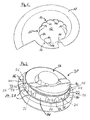
- Fig. 1 shows a sickle blade 10 with a large, central mounting hole 12.
- the mounting hole 12 is larger than, for example, a hole for passing a conventional mounting screw.
- the attachment opening 12 is substantially circular, but may also be formed, for example, as an oval, rectangle or polygon.
- the radius of the attachment opening 12 may be at least for example 1/10 of the largest radius of the sickle blade 10.
- the attachment opening 12 can also be significantly larger, so that only a comparatively small, the cutting edge comprehensive edge of the sickle blade 10 is left.
- the area or size of the attachment opening 12 may, for example, occupy at least one sixth of the surface of the sickle blade 10.
- the edge of the attachment opening 12 is formed "frayed". In particular, this has a meander shape.
- the edge of the attachment opening 12 may be wave-shaped. Alternatively, this can be designed in a star shape or, for example, in the manner of a thumbscrew. Other forms are conceivable.
- the knife 10 thus has an inwardly directed, non-circular contour.
- the sections, in particular knife projections 14, 14 ', which project further into the center of sickle blade 10, can be formed as tabs 14, 14'. These can for example be round or square.
- the inwardly directed projections 14, 14 ' can have the same thickness as a knife edge region adjoining the edge region. Alternatively, however, these could also be formed flattened and, for example be thinner than the remaining part of the knife, which adjoins the attachment opening 12.
- the knife projections 14, 14 ' form part of a bayonet closure 16. It is also conceivable to arrange a plurality of bayonet locks 16.
- Two of the knife projections 14 form a Verdeh Anlagen 17. This has two recesses 18, which can also be regarded as a recess 18 with two operatively connected end portions.
- a tab 14 ' is significantly larger.
- the tab 14 ' forms a kind of an open oval. At the point, the edge of the attachment opening 12 thus has an asymmetry.
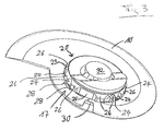
- Fig. 2 shows a knife holder 20.
- This has a ring 22 which forms a receiving edge region 22.
- the receiving edge portion 22 also serves as a mounting portion 22 for the sickle blade 10.
- the ring 22 is rotatably connected to a lid 34 and forms with this a first part 23 of the blade holder 20.
- This first part 23 is opposite a second part 30 of the blade holder 20, which a contact portion 30 for the knife 10, axially movable.
- the ring 22 has in particular recesses 24, 24 'and receiving projections 26 ("teeth"), which alternate. These are shaped in such a way that they correspond to the edge area 13 of the blade Fig. 1 correspond. Of the Ring 22 effectively represents the "positive” of the "negative” of the edge of the mounting aperture 12, ie the knife edge portion 13 and the ring 22 are complementary to one another.
- the ring 22 may have at least one recess 24 'which extends over a longer portion of the annular periphery than the remaining recesses 24.
- the recess 24 ' can in particular receive the tab 14'.
- a plurality of recesses 24 ' which can accommodate a plurality of tabs 14', for example.
- the blade holder 20 has at least one locking pin 28 which engages positively in the anti-rotation 17.
- two pins 28 are provided, of which for example one is movable and one fixed.
- the pins 28 engage with the recesses 18 of the rotation 17 in engagement.
- the sickle blade 10 is thus placed, for example by means of a handling device on the blade holder 20.
- the sickle blade 10 is in this case rotated until the tabs 14, 14 'correspond to the position of the recesses 24, 24'.
- the sickle blade 10 is now pushed over the ring 22 until it hits a support 30 and a support 30 of the second part 30 of the blade holder 20.
- the sickle blade 10 can be rotated again.
- the sickle blade 10 is adjusted counter to the direction of rotation in the cutting operation.
- the sickle blade 10 engages, for example via a locking pin 28 and is thus prevented from twisting.
- the sickle blade 10 is clearly positioned.
- At least one of the pins 28 may be formed stationary, while the other may be biased for example via a spring and jumps up when a recess 18 of the sickle blade 10 is above it.
- the actuation of at least one of the pins 28 may e.g. take place via the mentioned handling device of the knife 10.
- a counterweight 32 is shown.
- This outer counterweight 32 may, for example, be integrated at least partially into the blade receptacle 20.
- the counterweight 32 is fully integrated into the blade holder 20.
- the counterweight 32 may form part of the lid 34.
- the shape of the counterweight 32 may be different from the one in FIG Fig. 2 deviate form shown.
- the counterweight 32 may be flattened on the large sickle side of the sickle blade 10. It is also conceivable that the geometry of the blade holder 20 is even flattened on the large sickle side.
- the counterweight 32 Since the counterweight 32 is not mounted on or in front of the sickle blade 10, the counterweight 10 does not have to be disassembled when replacing the sickle blade 10.
- the counterweight 32 By the counterweight 32, the mass distribution can be adjusted. In particular, balancing of the rotating overall system is thereby possible. A static balance with respect to the axis of rotation is thereby generally guaranteed. Even a dynamic unbalance is countered by the arrangement of the counterweight 32 provided here.
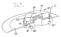
- Fig. 3 shows the sickle blade 10 according to Fig. 1 im on the blade holder 20 according to Fig. 2 attached condition. By placing, twisting and subsequent engagement of the pins 28 in the rotation 17, the sickle blade 10 is securely fixed in this position.
- the blade holder 20 locks with its mating contour, i. the projections 26, the contour, i. the tabs 14, 14 ', the knife 10. By this bayonet closure 16, an axial movement of the sickle blade 10 is prevented.
- the blade holder 20 For the final attachment of the sickle blade 10, the blade holder 20, the tabs 14, 14 'of the sickle blade 10 pinch. This is possible for example by means of screws within the blade holder 20. Alternatively, springs that are tensioned even with screws, for clamping the tabs 14, 14 'are used.
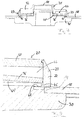
- the tabs 14, 14 ' is alternatively or additionally also a plate spring or a plate spring package 36 as a spring assembly 36 conceivable, which in Fig. 4 is shown.
- the disc springs 36 are biased such that the knife 10 is clamped in the normal state. Once the sickle blade 10 is in the correct position on the blade holder 20, ie in particular after the engagement of the pins 28, can the plate spring 36, the tabs 14, 14 'of the sickle blade 10 act and fix the knife 10.
- the knife 10 is thus clamped between the first part 23 and the second part 30 of the blade holder 20.
- the plate spring 36 can for example act directly on the tabs 14, 14 'of the sickle blade 10. However, the plate spring 36 preferably acts only indirectly via an inner side of the receiving edge region 22. This may have an inner projection 46 which is arranged between the plate spring 36 and the tabs 14, 14 'of the sickle blade 10. This is enlarged in Fig. 8 shown. The tongues 14, 14 'of the knife 10 are thus acted upon via the ring 22 by means of the plate spring 36.
- the sickle blade 10 is permanently fixed.
- Fig. 4 is also shown that on both sides of the knife plane counterweights 32, 32 'are arranged. Both counterweights 32, 32 'are respectively provided in the areas which face the small portion of the sickle blade 10.
- Fig. 5 and Fig. 6 show two further views of a sickle blade 10, which is mounted on a blade holder 20.
- FIGS. 7 and 8 A variant of the mentionedforceklemmung is in FIGS. 7 and 8 shown. To overcome the clamping an actuator is required.
- a pneumatic device for example, a pneumatic device may be provided.
- the cover 50 which forms a part of the counterweight 32 in particular at the same time, the receiving edge region 22 and the carrier 30 while an inner space 44, 44 'is sealed and pressurized.
- the entire, the plate spring 36-containing interior 44, 44 ' is pressurized or acted upon by an overpressure.
- the plate spring 36 rests on an inner projection 46 of the ring 22.
- the ring 22, the inner projection 46, the membrane 48 and the carrier 30 may be formed in particular as a one-piece component.
- the lid 50 of the blade holder 20 moves upward.
- the ring 22 is taken from the lid 50 and also moved upwards.
- the inner projection 46 and the plate spring 36 is moved radially outward against its bias up and thereby stretched more. Radially inside the plate spring 36 can not go further up, as it rests against a fixed shoulder.
- the knife 10 is thereby released.
- the membrane 48 thus ensures both a tightness of the inner space 44, 44 'and the required relative mobility of the components to cancel the clamping state.
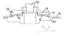
- a single screw 52 can be used as an actuating device, which in Fig. 9 is shown.
- multiple screws 52 may be used.
- clamping elements 52 as an actuating device conceivable. By turning the clamping screw 52, the plate spring 36 is additionally tensioned by this is pulled over the ring 22 upwards.
- the use of a clamping screw 52 has the advantage that this system is particularly simple.
- the clamping of the blade can therefore be overcome purely mechanically and / or pneumatically active.
Landscapes
- Engineering & Computer Science (AREA)
- Mechanical Engineering (AREA)
- Life Sciences & Earth Sciences (AREA)
- Forests & Forestry (AREA)
- Details Of Cutting Devices (AREA)
- Knives (AREA)
Applications Claiming Priority (2)
| Application Number | Priority Date | Filing Date | Title |
|---|---|---|---|
| DE201210007013 DE102012007013A1 (de) | 2012-04-05 | 2012-04-05 | Schnittstelle zwischen Messer und Messeraufnahme |
| EP13714301.2A EP2819815B2 (fr) | 2012-04-05 | 2013-04-05 | Interface entre un couteau et son dispositif de fixation |
Related Parent Applications (2)
| Application Number | Title | Priority Date | Filing Date |
|---|---|---|---|
| EP13714301.2A Division-Into EP2819815B2 (fr) | 2012-04-05 | 2013-04-05 | Interface entre un couteau et son dispositif de fixation |
| EP13714301.2A Division EP2819815B2 (fr) | 2012-04-05 | 2013-04-05 | Interface entre un couteau et son dispositif de fixation |
Publications (2)
| Publication Number | Publication Date |
|---|---|
| EP2835236A1 true EP2835236A1 (fr) | 2015-02-11 |
| EP2835236B1 EP2835236B1 (fr) | 2016-06-08 |
Family
ID=48048053
Family Applications (2)
| Application Number | Title | Priority Date | Filing Date |
|---|---|---|---|
| EP13714301.2A Not-in-force EP2819815B2 (fr) | 2012-04-05 | 2013-04-05 | Interface entre un couteau et son dispositif de fixation |
| EP14191512.4A Not-in-force EP2835236B1 (fr) | 2012-04-05 | 2013-04-05 | Logement de couteau pour machine pour la découpe de viande |
Family Applications Before (1)
| Application Number | Title | Priority Date | Filing Date |
|---|---|---|---|
| EP13714301.2A Not-in-force EP2819815B2 (fr) | 2012-04-05 | 2013-04-05 | Interface entre un couteau et son dispositif de fixation |
Country Status (4)
| Country | Link |
|---|---|
| US (2) | US9737942B2 (fr) |
| EP (2) | EP2819815B2 (fr) |
| DE (1) | DE102012007013A1 (fr) |
| WO (1) | WO2013150133A1 (fr) |
Families Citing this family (9)
| Publication number | Priority date | Publication date | Assignee | Title |
|---|---|---|---|---|
| DE102012007013A1 (de) | 2012-04-05 | 2013-10-10 | Weber Maschinenbau Gmbh Breidenbach | Schnittstelle zwischen Messer und Messeraufnahme |
| DE102016108346A1 (de) * | 2016-05-04 | 2017-11-09 | Weber Maschinenbau Gmbh Breidenbach | Vorrichtung und verfahren zum aufschneiden von lebensmittelprodukten |
| DE102016118212A1 (de) * | 2016-09-27 | 2018-03-29 | Weber Maschinenbau Gmbh Breidenbach | Schneidmesser |
| US20180281087A1 (en) * | 2017-03-27 | 2018-10-04 | JPL Global, LLC | System and methodology that facilitates a non-circular arbor design |
| KR102540973B1 (ko) * | 2020-05-14 | 2023-06-12 | 채성덕 | 연마패드 및 연마패드 장착용 그라인더 홀더 |
| DE102021115309A1 (de) * | 2021-06-14 | 2022-12-15 | Multivac Sepp Haggenmüller Se & Co. Kg | Aufschneide-Maschine mit Messer-Montagevorrichtung |
| US20230125230A1 (en) | 2021-10-25 | 2023-04-27 | Provisur Technologies, Inc. | Pivoting loading tray assembly for food product slicing apparatus and method of use |
| DE102023104231A1 (de) * | 2023-02-21 | 2024-08-22 | Multivac Sepp Haggenmüller Se & Co. Kg | Aufschneide-Maschine mit Messer-Fangvorrichtung |
| USD1124768S1 (en) * | 2023-10-27 | 2026-05-05 | Multivac Sepp Haggenmüller Se & Co. Kg | Cutting knife |
Citations (4)
| Publication number | Priority date | Publication date | Assignee | Title |
|---|---|---|---|---|
| EP1022101A2 (fr) * | 1999-01-25 | 2000-07-26 | Gebr. Graef GmbH & Co. KG | Garde pour la lame d'une machine de coupe |
| WO2007103899A2 (fr) * | 2006-03-08 | 2007-09-13 | Premark Feg L.L.C. | Couteau de trancheur de produit alimentaire, trancheur associe et outil de retrait de couteau |
| DE102008020293A1 (de) * | 2008-04-22 | 2009-10-29 | Maschinenbau Heinrich Hajek Gmbh & Co. | Hochgeschwindigkeitsschneidmaschine mit Halterung eines Sichelmesserrotors |
| DE202009017954U1 (de) * | 2009-03-09 | 2010-09-30 | Weber Maschinenbau Gmbh Breidenbach | Schneidmesser |
Family Cites Families (49)
| Publication number | Priority date | Publication date | Assignee | Title |
|---|---|---|---|---|
| US34754A (en) | 1862-03-25 | Improvement in steelyards | ||
| FR631683A (fr) * | 1927-02-07 | 1927-12-24 | Perfectionnements apportés aux machines à découper la viande ou les sauoissons | |
| CH125199A (de) | 1927-02-07 | 1928-04-02 | Adolf Warchalowski | Aufschnittschneidemaschine. |
| US1947662A (en) | 1933-02-20 | 1934-02-20 | Ind Of America Inc | Means for fastening wheels to spindles |
| US2600459A (en) | 1949-12-23 | 1952-06-17 | Ivan R Adams | Circular saw with adjustable arborreceiving openings |
| DE1265363B (de) | 1965-03-15 | 1968-04-04 | Federn Und Metallwarenfabrik | Rundmesser fuer eine Scheibenschneidemaschine fuer Lebensmittel |
| DE1629991A1 (de) | 1967-01-12 | 1971-03-11 | Kissing & Moellmann Metallware | Schneidemaschine fuer Nahrungsmittel mit Messerscheibe |
| US3610304A (en) * | 1969-11-24 | 1971-10-05 | Samuel J Popeil | Food-cutting machine |
| US3734548A (en) | 1971-12-20 | 1973-05-22 | K Tel International | Shaft connection mechanism |
| DE2320919C2 (de) | 1973-04-25 | 1991-06-20 | Ledermann Gmbh + Co, 7240 Horb | Schnellwechsel-Spannvorrichtung für Rotationswerkzeuge, insbesondere für Kreissägen |
| US3921485A (en) * | 1974-06-25 | 1975-11-25 | Itt | Rotary blade assembly |
| SU745674A1 (ru) * | 1978-05-04 | 1980-07-17 | Ленинградская Ордена Ленина Лесотехническая Академия Им. С.М.Кирова | Устройство дл установки круглых пил на пильном валу |
| US4660453A (en) | 1985-05-28 | 1987-04-28 | Urschel Laboratories, Inc. | Circular knife and method of making same |
| IT208084Z2 (it) | 1985-11-12 | 1988-03-31 | Cavagna Elio Srl | Portalama con lama circolare rapidamente intercambiabile. |
| US4730952A (en) | 1986-08-04 | 1988-03-15 | Wiley Edward R | Quick change mechanism for circular saw blades |
| DE3935485A1 (de) * | 1988-10-28 | 1990-05-03 | Weinig Michael Ag | Spannvorrichtung fuer werkzeuge, insbesondere fuer schleifscheiben |
| IT1238239B (it) * | 1990-02-08 | 1993-07-12 | Selco Srl | Mandrino porta lama a disco particolarmente per macchine sezionatrici. |
| DE4031671C2 (de) | 1990-10-05 | 1994-02-24 | Natec Reich Summer Gmbh Co Kg | Kreismesser zum Schneiden von Lebensmitteln, insbesondere Wurst und Käse |
| DE4114059C2 (de) * | 1991-04-30 | 2000-05-31 | Dienes Werke | Messerhalter mit Schnellwechselvorrichtung für das Messer |
| EP0569767B1 (fr) | 1992-05-13 | 1996-01-03 | SCHOBER GmbH Werkzeug- und Maschinenbau | Support de couteau |
| DE19612375A1 (de) * | 1996-03-28 | 1997-10-02 | Holzma Maschinenbau Gmbh | Vorrichtung zum Festspannen scheibenförmiger Werkzeuge, wie Kreissägeblätter, zwischen einem Festflansch und einem Losflansch einer Arbeitsspindel |
| USD394530S (en) | 1997-03-28 | 1998-05-19 | Minnesota Mining And Manufacturing Company | Surface treating article retainer system |
| JPH1199460A (ja) * | 1997-09-29 | 1999-04-13 | Yanase Kk | 回転研磨具 |
| US5989116A (en) | 1998-02-03 | 1999-11-23 | Swift & Company, Inc. | High-speed bone-in loin slicer |
| DE19822104C2 (de) | 1998-05-11 | 2000-05-04 | Mws Schneidwerkzeuge Gmbh | Rundmesser, insbesondere für Allesschneider |
| IL125766A (en) | 1998-08-13 | 2002-12-01 | Iscar Ltd | Tool shank and a replaceable cutting head for mounting thereon in a self-clamping manner |
| USD427042S (en) * | 1999-09-14 | 2000-06-27 | Black & Decker Inc. | Cutting tool hole |
| CA2290178A1 (fr) | 1999-03-08 | 2000-09-08 | Black & Decker Inc. | Lame de scie et dispositif de montage de lame |
| US6450075B1 (en) | 1999-06-25 | 2002-09-17 | Alex Manzo | Ventilated air cooled cutting system |
| US6227092B1 (en) | 1999-06-29 | 2001-05-08 | Dienes Corporation | Quick disconnect for a motor driven slitting knife |
| DE10041210C2 (de) * | 1999-08-30 | 2002-07-11 | Otto Martin Maschb Gmbh Fa | Kreissägemaschine |
| DE10044999A1 (de) | 1999-10-04 | 2001-05-03 | Peter Baumgaertner | Werkzeugdorn, insbesondere Fräs- oder Sägedorn |
| DE10017457A1 (de) * | 2000-04-07 | 2001-10-11 | Bosch Gmbh Robert | Schleifmaschinenwerkzeugaufnahme |
| DE10108018B4 (de) | 2001-02-19 | 2006-02-02 | Karl Dietrich Schiller | Rotationsmesser |
| US7287310B2 (en) * | 2003-02-06 | 2007-10-30 | Edward Zuzelo | Method of forming and attaching a blade that can receive both symmetrical and asymmetrical arbors |
| US7533839B2 (en) * | 2006-11-20 | 2009-05-19 | Michilin Prosperity Co., Ltd | Cutting blade and rotary cutting assembly for shredders |
| US20050192585A1 (en) * | 2004-02-27 | 2005-09-01 | Medtronic, Inc. | Surgical saw collet with closed drive ring |
| DE102004035627B3 (de) | 2004-07-22 | 2006-05-18 | Schührer, Bernhard | Vorrichtung zur Kopplung zweier Bauteile und eine Verwendung einer derartigen Vorrichtung |
| DE102004051669B4 (de) | 2004-10-22 | 2019-07-25 | Hebumedical Gmbh | Selbstsichernde Schraube und selbstsichernde Befestigungsanordnung |
| DE102005034476A1 (de) * | 2005-07-20 | 2007-01-25 | Albert Schrem Werkzeugfabrik Gmbh | Hydraulische Spannvorrichtung zum radialen und axialen Spannen |
| DE102008019776A1 (de) | 2008-04-18 | 2009-10-22 | CFS Bühl GmbH | Verfahren, Vorrichtung sowie Messer zum Aufschneiden von Lebensmitteln |
| CN201597020U (zh) | 2009-07-01 | 2010-10-06 | 蔡吕乾 | 一种摆式工具工作头 |
| DE102009032974A1 (de) † | 2009-07-14 | 2011-01-20 | Weber Maschinenbau Gmbh Breidenbach | Vorrichtung zum Aufschneiden von Lebensmittelprodukten |
| US8776657B2 (en) * | 2010-01-26 | 2014-07-15 | Robert Bosch Gmbh | Blade mounting assembly |
| CN201711607U (zh) | 2010-05-11 | 2011-01-19 | 南京德朔实业有限公司 | 用于振荡式电动工具的工作元件 |
| CH703182A1 (de) | 2010-05-26 | 2011-11-30 | Berner Fachhochschule Biel Architektur Holz Und Bau | Einrichtung zum Zentrieren von Kreissägeblättern und ähnlichen Werkzeugen auf der Welle. |
| USD638863S1 (en) * | 2010-11-19 | 2011-05-31 | Jae Hwan Huh | Grinding wheel blade |
| CN202045628U (zh) | 2010-12-11 | 2011-11-23 | 蔡吕乾 | 一种摆式工具工作头和转接器 |
| DE102012007013A1 (de) | 2012-04-05 | 2013-10-10 | Weber Maschinenbau Gmbh Breidenbach | Schnittstelle zwischen Messer und Messeraufnahme |
-
2012
- 2012-04-05 DE DE201210007013 patent/DE102012007013A1/de not_active Withdrawn
-
2013
- 2013-04-05 EP EP13714301.2A patent/EP2819815B2/fr not_active Not-in-force
- 2013-04-05 WO PCT/EP2013/057186 patent/WO2013150133A1/fr not_active Ceased
- 2013-04-05 EP EP14191512.4A patent/EP2835236B1/fr not_active Not-in-force
-
2014
- 2014-10-03 US US14/506,207 patent/US9737942B2/en not_active Expired - Fee Related
- 2014-10-03 US US14/506,190 patent/US9962782B2/en not_active Expired - Fee Related
Patent Citations (4)
| Publication number | Priority date | Publication date | Assignee | Title |
|---|---|---|---|---|
| EP1022101A2 (fr) * | 1999-01-25 | 2000-07-26 | Gebr. Graef GmbH & Co. KG | Garde pour la lame d'une machine de coupe |
| WO2007103899A2 (fr) * | 2006-03-08 | 2007-09-13 | Premark Feg L.L.C. | Couteau de trancheur de produit alimentaire, trancheur associe et outil de retrait de couteau |
| DE102008020293A1 (de) * | 2008-04-22 | 2009-10-29 | Maschinenbau Heinrich Hajek Gmbh & Co. | Hochgeschwindigkeitsschneidmaschine mit Halterung eines Sichelmesserrotors |
| DE202009017954U1 (de) * | 2009-03-09 | 2010-09-30 | Weber Maschinenbau Gmbh Breidenbach | Schneidmesser |
Also Published As
| Publication number | Publication date |
|---|---|
| EP2819815A1 (fr) | 2015-01-07 |
| US9737942B2 (en) | 2017-08-22 |
| EP2835236B1 (fr) | 2016-06-08 |
| EP2819815B1 (fr) | 2016-05-25 |
| US20150090091A1 (en) | 2015-04-02 |
| EP2819815B2 (fr) | 2019-06-26 |
| US9962782B2 (en) | 2018-05-08 |
| US20150090093A1 (en) | 2015-04-02 |
| DE102012007013A1 (de) | 2013-10-10 |
| WO2013150133A1 (fr) | 2013-10-10 |
Similar Documents
| Publication | Publication Date | Title |
|---|---|---|
| EP2819815B2 (fr) | Interface entre un couteau et son dispositif de fixation | |
| EP0569767B1 (fr) | Support de couteau | |
| EP0258771A2 (fr) | Mandrin | |
| EP2929992B1 (fr) | Logement de couteau pour une machine à découper | |
| EP2414114B1 (fr) | Outil de poinçonnage | |
| EP2939773B1 (fr) | Dispositif de serrage | |
| DE102012007924B4 (de) | Handwerkzeug mit einer Spannvorrichtung | |
| DE202013103278U1 (de) | Spannvorrichtung | |
| EP1501678B9 (fr) | Machine de serigraphie | |
| DE212016000229U1 (de) | Schleifmaschine | |
| EP4186464B1 (fr) | Porte-ébauche et ébauche | |
| EP1549983B1 (fr) | Porte-filtres | |
| EP0583737B1 (fr) | Outil de travail, notamment dispositif à couper, comme coupe-fil | |
| EP3892420B1 (fr) | Outil électrique | |
| WO2011026557A1 (fr) | Fraise à rectifier les alésages | |
| EP3486035B1 (fr) | Système de fixation destiné à fixer un outil à un logement d'outil ainsi que clé d'outil associée | |
| DE202013103989U1 (de) | Schneideinrichtung | |
| DE2817381C2 (fr) | ||
| EP2829340B1 (fr) | Dispositif de serrage | |
| EP4188723B1 (fr) | Plaque de serrage en forme de disque avec des machoires | |
| DE69908719T2 (de) | Ausbrechwerkzeug für kartonagezuschnitte | |
| DE3925426C2 (fr) | ||
| EP4522391A1 (fr) | Élément de blocage pour unité de freinage d'urgence de dispositif de sciage, et dispositif de sciage | |
| EP4219073A1 (fr) | Dispositif outil rotatif à entraînement rotatif | |
| WO2025171965A1 (fr) | Outil de coupe, en particulier cisailles ou ciseaux, à lames élastiquement précontraintes l'une par rapport à l'autre |
Legal Events
| Date | Code | Title | Description |
|---|---|---|---|
| PUAI | Public reference made under article 153(3) epc to a published international application that has entered the european phase |
Free format text: ORIGINAL CODE: 0009012 |
|
| 17P | Request for examination filed |
Effective date: 20141103 |
|
| AC | Divisional application: reference to earlier application |
Ref document number: 2819815 Country of ref document: EP Kind code of ref document: P |
|
| AK | Designated contracting states |
Kind code of ref document: A1 Designated state(s): AL AT BE BG CH CY CZ DE DK EE ES FI FR GB GR HR HU IE IS IT LI LT LU LV MC MK MT NL NO PL PT RO RS SE SI SK SM TR |
|
| AX | Request for extension of the european patent |
Extension state: BA ME |
|
| R17P | Request for examination filed (corrected) |
Effective date: 20150430 |
|
| RBV | Designated contracting states (corrected) |
Designated state(s): AL AT BE BG CH CY CZ DE DK EE ES FI FR GB GR HR HU IE IS IT LI LT LU LV MC MK MT NL NO PL PT RO RS SE SI SK SM TR |
|
| GRAP | Despatch of communication of intention to grant a patent |
Free format text: ORIGINAL CODE: EPIDOSNIGR1 |
|
| INTG | Intention to grant announced |
Effective date: 20151211 |
|
| GRAS | Grant fee paid |
Free format text: ORIGINAL CODE: EPIDOSNIGR3 |
|
| GRAA | (expected) grant |
Free format text: ORIGINAL CODE: 0009210 |
|
| AC | Divisional application: reference to earlier application |
Ref document number: 2819815 Country of ref document: EP Kind code of ref document: P |
|
| AK | Designated contracting states |
Kind code of ref document: B1 Designated state(s): AL AT BE BG CH CY CZ DE DK EE ES FI FR GB GR HR HU IE IS IT LI LT LU LV MC MK MT NL NO PL PT RO RS SE SI SK SM TR |
|
| REG | Reference to a national code |
Ref country code: GB Ref legal event code: FG4D Free format text: NOT ENGLISH |
|
| REG | Reference to a national code |
Ref country code: CH Ref legal event code: EP |
|
| REG | Reference to a national code |
Ref country code: IE Ref legal event code: FG4D Free format text: LANGUAGE OF EP DOCUMENT: GERMAN |
|
| REG | Reference to a national code |
Ref country code: AT Ref legal event code: REF Ref document number: 804874 Country of ref document: AT Kind code of ref document: T Effective date: 20160715 |
|
| REG | Reference to a national code |
Ref country code: DE Ref legal event code: R096 Ref document number: 502013003376 Country of ref document: DE |
|
| REG | Reference to a national code |
Ref country code: LT Ref legal event code: MG4D |
|
| REG | Reference to a national code |
Ref country code: NL Ref legal event code: MP Effective date: 20160608 |
|
| PG25 | Lapsed in a contracting state [announced via postgrant information from national office to epo] |
Ref country code: NO Free format text: LAPSE BECAUSE OF FAILURE TO SUBMIT A TRANSLATION OF THE DESCRIPTION OR TO PAY THE FEE WITHIN THE PRESCRIBED TIME-LIMIT Effective date: 20160908 Ref country code: FI Free format text: LAPSE BECAUSE OF FAILURE TO SUBMIT A TRANSLATION OF THE DESCRIPTION OR TO PAY THE FEE WITHIN THE PRESCRIBED TIME-LIMIT Effective date: 20160608 Ref country code: LT Free format text: LAPSE BECAUSE OF FAILURE TO SUBMIT A TRANSLATION OF THE DESCRIPTION OR TO PAY THE FEE WITHIN THE PRESCRIBED TIME-LIMIT Effective date: 20160608 |
|
| PG25 | Lapsed in a contracting state [announced via postgrant information from national office to epo] |
Ref country code: GR Free format text: LAPSE BECAUSE OF FAILURE TO SUBMIT A TRANSLATION OF THE DESCRIPTION OR TO PAY THE FEE WITHIN THE PRESCRIBED TIME-LIMIT Effective date: 20160909 Ref country code: SE Free format text: LAPSE BECAUSE OF FAILURE TO SUBMIT A TRANSLATION OF THE DESCRIPTION OR TO PAY THE FEE WITHIN THE PRESCRIBED TIME-LIMIT Effective date: 20160608 Ref country code: NL Free format text: LAPSE BECAUSE OF FAILURE TO SUBMIT A TRANSLATION OF THE DESCRIPTION OR TO PAY THE FEE WITHIN THE PRESCRIBED TIME-LIMIT Effective date: 20160608 Ref country code: LV Free format text: LAPSE BECAUSE OF FAILURE TO SUBMIT A TRANSLATION OF THE DESCRIPTION OR TO PAY THE FEE WITHIN THE PRESCRIBED TIME-LIMIT Effective date: 20160608 Ref country code: HR Free format text: LAPSE BECAUSE OF FAILURE TO SUBMIT A TRANSLATION OF THE DESCRIPTION OR TO PAY THE FEE WITHIN THE PRESCRIBED TIME-LIMIT Effective date: 20160608 Ref country code: RS Free format text: LAPSE BECAUSE OF FAILURE TO SUBMIT A TRANSLATION OF THE DESCRIPTION OR TO PAY THE FEE WITHIN THE PRESCRIBED TIME-LIMIT Effective date: 20160608 Ref country code: ES Free format text: LAPSE BECAUSE OF FAILURE TO SUBMIT A TRANSLATION OF THE DESCRIPTION OR TO PAY THE FEE WITHIN THE PRESCRIBED TIME-LIMIT Effective date: 20160608 |
|
| PG25 | Lapsed in a contracting state [announced via postgrant information from national office to epo] |
Ref country code: RO Free format text: LAPSE BECAUSE OF FAILURE TO SUBMIT A TRANSLATION OF THE DESCRIPTION OR TO PAY THE FEE WITHIN THE PRESCRIBED TIME-LIMIT Effective date: 20160608 Ref country code: CZ Free format text: LAPSE BECAUSE OF FAILURE TO SUBMIT A TRANSLATION OF THE DESCRIPTION OR TO PAY THE FEE WITHIN THE PRESCRIBED TIME-LIMIT Effective date: 20160608 Ref country code: IS Free format text: LAPSE BECAUSE OF FAILURE TO SUBMIT A TRANSLATION OF THE DESCRIPTION OR TO PAY THE FEE WITHIN THE PRESCRIBED TIME-LIMIT Effective date: 20161008 Ref country code: EE Free format text: LAPSE BECAUSE OF FAILURE TO SUBMIT A TRANSLATION OF THE DESCRIPTION OR TO PAY THE FEE WITHIN THE PRESCRIBED TIME-LIMIT Effective date: 20160608 Ref country code: SK Free format text: LAPSE BECAUSE OF FAILURE TO SUBMIT A TRANSLATION OF THE DESCRIPTION OR TO PAY THE FEE WITHIN THE PRESCRIBED TIME-LIMIT Effective date: 20160608 |
|
| PG25 | Lapsed in a contracting state [announced via postgrant information from national office to epo] |
Ref country code: SM Free format text: LAPSE BECAUSE OF FAILURE TO SUBMIT A TRANSLATION OF THE DESCRIPTION OR TO PAY THE FEE WITHIN THE PRESCRIBED TIME-LIMIT Effective date: 20160608 Ref country code: PT Free format text: LAPSE BECAUSE OF FAILURE TO SUBMIT A TRANSLATION OF THE DESCRIPTION OR TO PAY THE FEE WITHIN THE PRESCRIBED TIME-LIMIT Effective date: 20161010 Ref country code: PL Free format text: LAPSE BECAUSE OF FAILURE TO SUBMIT A TRANSLATION OF THE DESCRIPTION OR TO PAY THE FEE WITHIN THE PRESCRIBED TIME-LIMIT Effective date: 20160608 |
|
| REG | Reference to a national code |
Ref country code: DE Ref legal event code: R097 Ref document number: 502013003376 Country of ref document: DE |
|
| PLBE | No opposition filed within time limit |
Free format text: ORIGINAL CODE: 0009261 |
|
| STAA | Information on the status of an ep patent application or granted ep patent |
Free format text: STATUS: NO OPPOSITION FILED WITHIN TIME LIMIT |
|
| REG | Reference to a national code |
Ref country code: FR Ref legal event code: PLFP Year of fee payment: 5 |
|
| 26N | No opposition filed |
Effective date: 20170309 |
|
| PG25 | Lapsed in a contracting state [announced via postgrant information from national office to epo] |
Ref country code: SI Free format text: LAPSE BECAUSE OF FAILURE TO SUBMIT A TRANSLATION OF THE DESCRIPTION OR TO PAY THE FEE WITHIN THE PRESCRIBED TIME-LIMIT Effective date: 20160608 Ref country code: DK Free format text: LAPSE BECAUSE OF FAILURE TO SUBMIT A TRANSLATION OF THE DESCRIPTION OR TO PAY THE FEE WITHIN THE PRESCRIBED TIME-LIMIT Effective date: 20160608 |
|
| REG | Reference to a national code |
Ref country code: CH Ref legal event code: PL |
|
| REG | Reference to a national code |
Ref country code: IE Ref legal event code: MM4A |
|
| PG25 | Lapsed in a contracting state [announced via postgrant information from national office to epo] |
Ref country code: MC Free format text: LAPSE BECAUSE OF FAILURE TO SUBMIT A TRANSLATION OF THE DESCRIPTION OR TO PAY THE FEE WITHIN THE PRESCRIBED TIME-LIMIT Effective date: 20160608 |
|
| PG25 | Lapsed in a contracting state [announced via postgrant information from national office to epo] |
Ref country code: LU Free format text: LAPSE BECAUSE OF NON-PAYMENT OF DUE FEES Effective date: 20170405 Ref country code: CH Free format text: LAPSE BECAUSE OF NON-PAYMENT OF DUE FEES Effective date: 20170430 Ref country code: LI Free format text: LAPSE BECAUSE OF NON-PAYMENT OF DUE FEES Effective date: 20170430 |
|
| REG | Reference to a national code |
Ref country code: BE Ref legal event code: MM Effective date: 20170430 |
|
| PG25 | Lapsed in a contracting state [announced via postgrant information from national office to epo] |
Ref country code: IE Free format text: LAPSE BECAUSE OF NON-PAYMENT OF DUE FEES Effective date: 20170405 |
|
| PG25 | Lapsed in a contracting state [announced via postgrant information from national office to epo] |
Ref country code: BE Free format text: LAPSE BECAUSE OF NON-PAYMENT OF DUE FEES Effective date: 20170430 |
|
| PG25 | Lapsed in a contracting state [announced via postgrant information from national office to epo] |
Ref country code: MT Free format text: LAPSE BECAUSE OF FAILURE TO SUBMIT A TRANSLATION OF THE DESCRIPTION OR TO PAY THE FEE WITHIN THE PRESCRIBED TIME-LIMIT Effective date: 20160608 |
|
| PG25 | Lapsed in a contracting state [announced via postgrant information from national office to epo] |
Ref country code: AL Free format text: LAPSE BECAUSE OF FAILURE TO SUBMIT A TRANSLATION OF THE DESCRIPTION OR TO PAY THE FEE WITHIN THE PRESCRIBED TIME-LIMIT Effective date: 20160608 |
|
| PG25 | Lapsed in a contracting state [announced via postgrant information from national office to epo] |
Ref country code: FR Free format text: LAPSE BECAUSE OF NON-PAYMENT OF DUE FEES Effective date: 20180430 |
|
| REG | Reference to a national code |
Ref country code: AT Ref legal event code: MM01 Ref document number: 804874 Country of ref document: AT Kind code of ref document: T Effective date: 20180405 |
|
| PG25 | Lapsed in a contracting state [announced via postgrant information from national office to epo] |
Ref country code: HU Free format text: LAPSE BECAUSE OF FAILURE TO SUBMIT A TRANSLATION OF THE DESCRIPTION OR TO PAY THE FEE WITHIN THE PRESCRIBED TIME-LIMIT; INVALID AB INITIO Effective date: 20130405 |
|
| PGFP | Annual fee paid to national office [announced via postgrant information from national office to epo] |
Ref country code: IT Payment date: 20190419 Year of fee payment: 7 |
|
| PG25 | Lapsed in a contracting state [announced via postgrant information from national office to epo] |
Ref country code: BG Free format text: LAPSE BECAUSE OF FAILURE TO SUBMIT A TRANSLATION OF THE DESCRIPTION OR TO PAY THE FEE WITHIN THE PRESCRIBED TIME-LIMIT Effective date: 20160608 |
|
| PG25 | Lapsed in a contracting state [announced via postgrant information from national office to epo] |
Ref country code: AT Free format text: LAPSE BECAUSE OF NON-PAYMENT OF DUE FEES Effective date: 20180405 Ref country code: CY Free format text: LAPSE BECAUSE OF FAILURE TO SUBMIT A TRANSLATION OF THE DESCRIPTION OR TO PAY THE FEE WITHIN THE PRESCRIBED TIME-LIMIT Effective date: 20160608 |
|
| PGFP | Annual fee paid to national office [announced via postgrant information from national office to epo] |
Ref country code: GB Payment date: 20190424 Year of fee payment: 7 |
|
| PG25 | Lapsed in a contracting state [announced via postgrant information from national office to epo] |
Ref country code: MK Free format text: LAPSE BECAUSE OF FAILURE TO SUBMIT A TRANSLATION OF THE DESCRIPTION OR TO PAY THE FEE WITHIN THE PRESCRIBED TIME-LIMIT Effective date: 20160608 |
|
| PG25 | Lapsed in a contracting state [announced via postgrant information from national office to epo] |
Ref country code: TR Free format text: LAPSE BECAUSE OF FAILURE TO SUBMIT A TRANSLATION OF THE DESCRIPTION OR TO PAY THE FEE WITHIN THE PRESCRIBED TIME-LIMIT Effective date: 20160608 |
|
| GBPC | Gb: european patent ceased through non-payment of renewal fee |
Effective date: 20200405 |
|
| PG25 | Lapsed in a contracting state [announced via postgrant information from national office to epo] |
Ref country code: GB Free format text: LAPSE BECAUSE OF NON-PAYMENT OF DUE FEES Effective date: 20200405 |
|
| PG25 | Lapsed in a contracting state [announced via postgrant information from national office to epo] |
Ref country code: IT Free format text: LAPSE BECAUSE OF NON-PAYMENT OF DUE FEES Effective date: 20200405 |
|
| P01 | Opt-out of the competence of the unified patent court (upc) registered |
Effective date: 20230522 |
|
| PGFP | Annual fee paid to national office [announced via postgrant information from national office to epo] |
Ref country code: DE Payment date: 20230418 Year of fee payment: 11 |
|
| REG | Reference to a national code |
Ref country code: DE Ref legal event code: R081 Ref document number: 502013003376 Country of ref document: DE Owner name: WEBER FOOD TECHNOLOGY GMBH, DE Free format text: FORMER OWNER: WEBER MASCHINENBAU GMBH BREIDENBACH, 35236 BREIDENBACH, DE |
|
| REG | Reference to a national code |
Ref country code: DE Ref legal event code: R119 Ref document number: 502013003376 Country of ref document: DE |
|
| PG25 | Lapsed in a contracting state [announced via postgrant information from national office to epo] |
Ref country code: DE Free format text: LAPSE BECAUSE OF NON-PAYMENT OF DUE FEES Effective date: 20241105 |
|
| PG25 | Lapsed in a contracting state [announced via postgrant information from national office to epo] |
Ref country code: DE Free format text: LAPSE BECAUSE OF NON-PAYMENT OF DUE FEES Effective date: 20241105 |