EP2835606B1 - Circulateur à température constante - Google Patents
Circulateur à température constante Download PDFInfo
- Publication number
- EP2835606B1 EP2835606B1 EP14183780.7A EP14183780A EP2835606B1 EP 2835606 B1 EP2835606 B1 EP 2835606B1 EP 14183780 A EP14183780 A EP 14183780A EP 2835606 B1 EP2835606 B1 EP 2835606B1
- Authority
- EP
- European Patent Office
- Prior art keywords
- constant temperature
- controller
- housing
- temperature circulator
- circulator
- Prior art date
- Legal status (The legal status is an assumption and is not a legal conclusion. Google has not performed a legal analysis and makes no representation as to the accuracy of the status listed.)
- Active
Links
Images




Classifications
-
- F—MECHANICAL ENGINEERING; LIGHTING; HEATING; WEAPONS; BLASTING
- F25—REFRIGERATION OR COOLING; COMBINED HEATING AND REFRIGERATION SYSTEMS; HEAT PUMP SYSTEMS; MANUFACTURE OR STORAGE OF ICE; LIQUEFACTION SOLIDIFICATION OF GASES
- F25D—REFRIGERATORS; COLD ROOMS; ICE-BOXES; COOLING OR FREEZING APPARATUS NOT OTHERWISE PROVIDED FOR
- F25D31/00—Other cooling or freezing apparatus
- F25D31/002—Liquid coolers, e.g. beverage cooler
- F25D31/003—Liquid coolers, e.g. beverage cooler with immersed cooling element
-
- B—PERFORMING OPERATIONS; TRANSPORTING
- B01—PHYSICAL OR CHEMICAL PROCESSES OR APPARATUS IN GENERAL
- B01L—CHEMICAL OR PHYSICAL LABORATORY APPARATUS FOR GENERAL USE
- B01L7/00—Heating or cooling apparatus; Heat insulating devices
- B01L7/02—Water baths; Sand baths; Air baths
-
- B—PERFORMING OPERATIONS; TRANSPORTING
- B01—PHYSICAL OR CHEMICAL PROCESSES OR APPARATUS IN GENERAL
- B01L—CHEMICAL OR PHYSICAL LABORATORY APPARATUS FOR GENERAL USE
- B01L2200/00—Solutions for specific problems relating to chemical or physical laboratory apparatus
- B01L2200/14—Process control and prevention of errors
- B01L2200/143—Quality control, feedback systems
- B01L2200/147—Employing temperature sensors
-
- B—PERFORMING OPERATIONS; TRANSPORTING
- B01—PHYSICAL OR CHEMICAL PROCESSES OR APPARATUS IN GENERAL
- B01L—CHEMICAL OR PHYSICAL LABORATORY APPARATUS FOR GENERAL USE
- B01L2300/00—Additional constructional details
- B01L2300/18—Means for temperature control
- B01L2300/1805—Conductive heating, heat from thermostatted solids is conducted to receptacles, e.g. heating plates, blocks
- B01L2300/1827—Conductive heating, heat from thermostatted solids is conducted to receptacles, e.g. heating plates, blocks using resistive heater
-
- B—PERFORMING OPERATIONS; TRANSPORTING
- B01—PHYSICAL OR CHEMICAL PROCESSES OR APPARATUS IN GENERAL
- B01L—CHEMICAL OR PHYSICAL LABORATORY APPARATUS FOR GENERAL USE
- B01L2400/00—Moving or stopping fluids
- B01L2400/04—Moving fluids with specific forces or mechanical means
- B01L2400/0475—Moving fluids with specific forces or mechanical means specific mechanical means and fluid pressure
Definitions
- the present disclosure is related to a constant temperature circulator, and more particularly, to an improved constant temperature circulator including, among other things, an integrally molded housing that encapsulates all associated components.
- constant temperature circulators have many disadvantages, only some of which are described herein.
- conventional constant temperature circulators include a stainless-steel box enclosing various electrical components. Circulation and heating components depend unprotected from the box.
- One disadvantage of the box construction is that the box is made of multiple components and as a result tolerance stack up is a prevalent issue. In fact, significant efforts have been expended to reduce such tolerance issues, considerably raising the costs to manufacture.
- Another disadvantage is the lack of protection for the depending components (i.e., heating element, pump/circulation and temperature sensor) not only such that such components are not damaged, but also that the contents of any container into which the circulator is inserted are not damaged.
- the present invention provides a constant temperature circulator for maintaining a liquid at a constant temperature, comprising a housing that encapsulates a controller, a display connected to the controller, a heating element connected to the controller, a temperature sensor connected to the controller, and an electric motor connected to the controller including an output shaft having an impeller, wherein the housing is at least a two-piece construction where each piece is moulded, and wherein the housing further includes an edge disposed in a lower portion to define a skirt cavity below a chamber to prevent objects that may be disposed in the liquid from contacting the impeller, heating element or output shaft, wherein the controller includes a processor and a memory capable of storing data for use by the processor, wherein the display is a liquid crystal display, and wherein the controller is capable of commanding the impeller to be operated by the electric motor in a clockwise or a counter-clockwise direction.
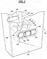
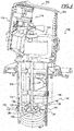
- FIG. 1 is a partially exploded view of an constant temperature circulator 100 in accordance with one embodiment of the present disclosure and FIG. 4 is a cross-section view of the constant temperature circulator of FIG. 2 along line 4-4.
- the constant temperature circulator 100 may include a housing 104 that encapsulates a controller 114, a display (116, see FIG. 2 ) connected to the controller 114, a heating element 118 connected to the controller 114, a temperature sensor 120 connected to the controller 114, and an electric motor 122 connected to the controller 114 including an output shaft 124 having an impeller 126.
- the housing 104 may be formed of any suitable material to perform the intended functionality.
- the housing 104 is at least a two piece construction, where each piece is made by any suitable molding process that facilitates the tight control of tolerances.
- a first integrally injection molded cover 106 is connected to a second integrally injection molded cover 108, where the second integrally injection molded cover 108 may comprise a top portion 110 and a bottom portion 112 that may simplify manufacturing and assembly.
- the housing 104 may be made from any suitable natural or synthetic material, such as metal, plastic, or composite.
- the housing 104 is made from a synthetic polymer, such as Polysulfone or a temperature rated glass filled nylon, such as may be available from RTP Company as part number RTP 900 P-1720 Polysulfone or Dupont as part number Zytel HTNFR52G20NH PPA.
- the housing 104 further includes an edge 178 disposed in the lower portion 148 to define a skirt cavity 180 below the chamber 136 to prevent objects that may be disposed in the liquid 102 from contacting the impeller 126, heating element 118 or output shaft 124.
- the controller 114, the display (116, see FIG. 2 ), the heating element 118, the temperature sensor 120, and the electric motor 122 may be preferably configured as conventional elements with conventional functionality.
- the controller 114 may be a device controller, digital controller, analog controller, chip, card, programmable logic controller, microcontroller, proportional-integral-derivative controller or any other suitable device that is used for automation of an electromechanical processes or to facilitate extensive input/output (I/O) communication with the display (116, see FIG. 2 ), the heating element 118, the temperature sensor 120, and the electric motor 122.
- the controller 114 includes a processor that may be, but not limited to, a single processor, plurality of processors, a DSP, a microprocessor, ASIC, state machine, or any other implementation capable of processing and executing software.
- the term processor should not be construed to refer exclusively to hardware capable of executing software, and may implicitly include DSP hardware, ROM for storing software, RAM, and any other volatile or non-volatile storage medium.
- the controller 114 includes memory that may be, but not limited to, a single memory, a plurality of memory locations, shared memory, CD, DVD, ROM, RAM, EEPROM, optical storage, microcode or any other non-volatile storage capable of storing digital data for use by the processor.
- the controller 114 may be a Microchip PIC single chip microcontroller that includes onboard RAM and ROM, receives an input from a PT1000 resistance temperature detector and from user interface keys and provides output to drive triacs for the electric motor and the impeller, the heater and the liquid crystal display.
- the controller 114 may include a set or sets of instructions to perform all of the following functions as described herein. It is within the teachings of the present disclosure that the instructions may be set forth in any suitable language or form in order to perform the intended functionality. Accordingly, for the sake of brevity this disclosure will not describe the exact instructions, but will rather describe the intended functionality of various aspects of the controller 114 below.
- the heating element 118, the temperature sensor 120, and the electric motor 122 may be any suitable version of such device that performs the intended functionality as is commonly understood with respect to such devices.
- the display (116, see FIG. 2 ) is a liquid crystal display, for example an LCD, LED, OLED, or a custom made "chip on glass" LED back lighted LCD manufactured by Liquid Crystal Technologies as part number LCT0065, backlight part no. LCT0070.
- the heating element 118 may be a Calrod, tubular type heater, or in one embodiment, an 1100 watt element housed in an Incoloy 800 sheath manufactured by Zoppas Industries, distributed as PolyScience part no.
- the temperature sensor 120 may be a platinum RTD (Resistive Temperature Device) or thermistor, thermocouple, silicon temperature sensor, or in one embodiment, a 1000 ohm platinum RTD manufactured by Tempco Electric, distributed as PolyScience part number 200-496, and the electric motor 122 may be an open or closed frame or shaded pole, or in one embodiment, an open frame shaded pole motor by March Manufacturing, distributed as PolyScience part no. 215-696 (120v), 215-697 (240v). It is further within the teachings of the present disclosure that any other suitable device that performs the similar functionality may be freely substituted therefore.
- the impeller 126 is configured to be operated by the electric motor 122, when commanded by the controller 114, in a clockwise or a counter-clockwise direction.
- an upper portion 146 may be defined in the housing 104 that contains the controller 114, display 116 and electric motor 122. It is within the teachings of the present disclosure that the upper portion 146 is generally that portion of the constant temperature circulator 100 that is not immersed into the liquid 102. Accordingly, the extent of the upper and lower portions 146, 148 may be different in certain situations subject to the teachings herein. In one embodiment, a lower portion 148 is defined in the housing 104 that is adapted and configured to be immersed into the liquid 102 (see, FIGS. 5 and 6 ).
- the impeller 126 may have any suitable configuration in order to perform the intended functionality as described herein.
- the impeller 126 may have a four bladed configuration, where the blades 128 are commonly connected to a center portion that is connected to a distal end 130 of the output shaft 124.
- Other suitable configurations, including multiple impellers, curved blades and other alternative embodiments may be freely substituted therefore.
- the housing 104 may include a first port 132 and a second port 134 that cooperatively define a chamber 136 that encapsulates, encompasses or otherwise generally complementarily encloses the impeller 126 (see also FIG. 4 ) such that the impeller 126 may function as commonly understood in a pump to move a fluid from an inlet to an outlet.
- the first and second ports 132, 134 may respectively include a first rim 138 and a second rim 140.
- the chamber 136 may be cooperatively defined by the first port 132 and the second port 134 and configured to complementarily encapsulate the impeller 126 when the first rim 138 abuts the second rim 140.
- an aperture 142 may be cooperatively defined by the first rim 138 and the second rim 140 that is in communication with the chamber 136. It is within the teachings of the present disclosure that the aperture 142 may have any suitable configuration or location.
- the aperture 142 is symmetrically formed in the first and second rims 138, 140 in a top portion of the respective first and second ports 132, 134 and disposed about a longitudinal axis 144 of the output shaft 124, such that actuation of the impeller 126 when the electric motor 122 is activated by the controller 114 moves the liquid 102 from the aperture 142, through the chamber 136 and to an outlet as described herein.
- FIG. 2 is a front elevation view of one embodiment of the constant temperature circulator 100 of FIG. 1 and FIG. 3 is detailed view of a highlighted portion of constant temperature circulator of FIG. 2 .
- one of the first and second integrally molded covers 106, 108 includes a first opening 150 (shown on the first integrally molded cover 106 solely for example and not by way of limitation). It is within the teachings of the present disclosure that the first opening 150 may have any suitable configuration to perform the intended functionality.
- the first opening 150 may be configured as generally symmetrical.
- the first opening 150 may be connected to and in communication with the first port 132 to define a distal outer extent of the first port 132.
- the first opening 150 is disposed in the lower portion 148.
- a first channel 152 may formed in the exterior surface of the housing 104 that is disposed within the lower portion 148. It is within the teachings of the present disclosure that the first channel 152 may have any suitable configuration to perform the intended functionality.
- the first channel 152 may be configured as a recessed portion in the exterior surface of the housing 104 wherein a portion of the first channel 152 may surround the first opening 150 or may be operatively associated with the first opening 150.
- a first adjuster 156 may be movably connected to the first channel 150 between a substantially closed position 158 restricting the first opening 150 and a substantially open position 160 unrestricting the first opening 150 to adjust a flow of the liquid 102 through the aperture 142 and the chamber 136. It is within the teachings of the present disclosure that the first adjuster 156 may be connected to the first channel 150 in any suitable manner to perform the intended functionality.
- the first adjuster 156 may be snap-fit, slidingly engage, or any other suitable movable connection.
- an other of the first and second integrally molded covers 106, 108 includes a second opening 162 (shown in FIGS. 3 and 5 on the second integrally molded cover 108 solely for example and not by way of limitation).
- the second opening 162 may have any suitable configuration to perform the intended functionality.
- the second opening 162 may be configured as generally symmetrical.
- the second opening 162 may be connected to and in communication with the second port 134 to define a distal outer extent of the second port 134.
- the second opening 162 is disposed in the lower portion 148.
- a second channel 164 may formed in the exterior surface of the housing 104 that is disposed within the lower portion 148.
- the second channel 164 may have any suitable configuration to perform the intended functionality.
- the second channel 164 may be configured as a recessed portion in the exterior surface of the housing 104 wherein a portion of the second channel 164 may surround the second opening 162 or may be operatively associated with the second opening 162.
- a second adjuster 166 may be movably connected to the second channel 162 between a substantially closed position 158 restricting the second opening 162 and a substantially open position 160 unrestricting the second opening 162 to adjust a flow of the liquid 102 through the aperture 142 and the chamber 136.
- the second adjuster 166 may be connected to the second channel 162 in any suitable manner to perform the intended functionality.
- the second adjuster 166 may be snap-fit, slidingly engage, or any other suitable movable connection.
- FIG. 5 is a rear elevation view of the constant temperature circulator of FIG. 2 that is a front elevation view of one embodiment of the constant temperature circulator 100 of FIG. 1 and FIG. 6 is a side elevation view of one embodiment of the constant temperature circulator of FIG. 1 .
- an outlet tube 168 may be connected to one of the first and second openings 150, 162 in order to facilitate connection to an external device to perform conditioning of the liquid 102, such as adjusting a temperature of the liquid 102, external to or remote from a container 170 for the liquid 102.
- the one of the first and second openings 150, 162 or both may be configured in any suitable manner to accept, receive, engage or otherwise facilitate direct connection of the outlet tube 168 or by way of a connector, coupling or other intermediate device.
- an other of the first and second openings 150, 162 is disposed in the closed position 158 so that liquid 102 drawn into the chamber 136 through the aperture 142 is discharged out the one of the first and second openings 150, 162 and the outlet tube 168.
- An inlet tube 172 may be provided to facilitate return of the liquid 102 to the container 170.
- the housing 104 may include a mounting element removably connected to the housing 104 so that the housing 104 may be removably connected to the container 170 for the liquid 102.
- the mounting element may have any suitable configuration to perform the intended functionality.
- the mounting element may be configured as a clamp 174 (for engaging a rim of the container 170) or a base ring 176 (for covering an opening of the container 170).
- the clamp 174 and base ring 176 may be configured in any suitable manner to facilitate removable connection of the constant temperature circulator 100 to the container 170.
Landscapes
- Engineering & Computer Science (AREA)
- Chemical & Material Sciences (AREA)
- General Engineering & Computer Science (AREA)
- Physics & Mathematics (AREA)
- Mechanical Engineering (AREA)
- Thermal Sciences (AREA)
- Combustion & Propulsion (AREA)
- Health & Medical Sciences (AREA)
- Clinical Laboratory Science (AREA)
- Chemical Kinetics & Catalysis (AREA)
- Structures Of Non-Positive Displacement Pumps (AREA)
- External Artificial Organs (AREA)
- Control Of Temperature (AREA)
Claims (7)
- Circulateur à température constante (100) permettant de maintenir un liquide (102) à une température constante, comportant un logement (104) qui encapsule un dispositif de régulation (114), un affichage (116) connecté au dispositif de régulation (114), un élément de chauffage (118) connecté au dispositif de régulation (114), un capteur de température (120) connecté au dispositif de régulation (114), et un moteur électrique (122) connecté au dispositif de régulation (114) comprenant un arbre de sortie (124) ayant une hélice (126), dans lequel le logement (104) est au moins une construction en deux pièces dans laquelle chaque pièce est moulée, et dans lequel le logement (104) comprend par ailleurs un bord (178) disposé dans une partie inférieure (148) pour définir une cavité formant jupe (180) sous une chambre (136) pour empêcher des objets qui peuvent être disposés dans le liquide (102) d'entrer en contact avec l'hélice (126), l'élément de chauffage (118) ou l'arbre de sortie (124), dans lequel le dispositif de régulation (114) comprend un processeur et une mémoire en mesure de stocker des données à des fins d'utilisation par le processeur, dans lequel l'affichage (116) est un affichage à cristaux liquides (LCD), et dans lequel le dispositif de régulation (114) est en mesure de commander le fonctionnement de l'hélice (126) par le moteur électrique (122) dans une direction allant dans le sens des aiguilles d'une montre ou dans une direction allant dans le sens inverse des aiguilles d'une montre.
- Circulateur à température constante (100) selon la revendication 1, dans lequel le logement comporte un premier capot moulé par injection en une seule pièce (106) connecté à un deuxième capot moulé par injection en une seule pièce (108).
- Circulateur à température constante (100) selon la revendication 1, dans lequel le logement (104) est réalisé à partir d'un métal.
- Circulateur à température constante (100) selon la revendication 1, dans lequel le logement (104) est réalisé à partir d'un matériau plastique.
- Circulateur à température constante (100) selon la revendication 1, dans lequel le logement (104) est réalisé à partir d'un matériau composite.
- Circulateur à température constante (100) selon la revendication 4, dans lequel le matériau plastique est du polymère synthétique, éventuellement du polysulfone ou un nylon armé de verre à température nominale.
- Circulateur à température constante (100) selon la revendication 2, dans lequel le deuxième capot moulé par injection en une seule pièce comporte une partie supérieure (110) et une partie inférieure (112).
Applications Claiming Priority (2)
| Application Number | Priority Date | Filing Date | Title |
|---|---|---|---|
| US12/699,365 US8469678B2 (en) | 2010-02-03 | 2010-02-03 | Constant temperature circulator |
| EP11152751.1A EP2354738B1 (fr) | 2010-02-03 | 2011-01-31 | Circulateur à température constante |
Related Parent Applications (1)
| Application Number | Title | Priority Date | Filing Date |
|---|---|---|---|
| EP11152751.1A Division EP2354738B1 (fr) | 2010-02-03 | 2011-01-31 | Circulateur à température constante |
Publications (3)
| Publication Number | Publication Date |
|---|---|
| EP2835606A2 EP2835606A2 (fr) | 2015-02-11 |
| EP2835606A3 EP2835606A3 (fr) | 2015-04-22 |
| EP2835606B1 true EP2835606B1 (fr) | 2018-10-31 |
Family
ID=44012411
Family Applications (2)
| Application Number | Title | Priority Date | Filing Date |
|---|---|---|---|
| EP14183780.7A Active EP2835606B1 (fr) | 2010-02-03 | 2011-01-31 | Circulateur à température constante |
| EP11152751.1A Active EP2354738B1 (fr) | 2010-02-03 | 2011-01-31 | Circulateur à température constante |
Family Applications After (1)
| Application Number | Title | Priority Date | Filing Date |
|---|---|---|---|
| EP11152751.1A Active EP2354738B1 (fr) | 2010-02-03 | 2011-01-31 | Circulateur à température constante |
Country Status (5)
| Country | Link |
|---|---|
| US (2) | US8469678B2 (fr) |
| EP (2) | EP2835606B1 (fr) |
| CN (1) | CN102192597B (fr) |
| DE (1) | DE202011052315U1 (fr) |
| ES (1) | ES2525761T3 (fr) |
Families Citing this family (25)
| Publication number | Priority date | Publication date | Assignee | Title |
|---|---|---|---|---|
| US9334876B2 (en) * | 2011-04-12 | 2016-05-10 | Thermo Neslab Inc. | Pump casing and related apparatus and methods |
| US20130169207A1 (en) * | 2012-01-03 | 2013-07-04 | General Electric Company | Method and device for protecting an inverter power switching semiconductor device from thermal cycling |
| WO2013130798A1 (fr) * | 2012-02-29 | 2013-09-06 | Nomiku Inc. | Appareil et système de cuisson à basse température |
| US9826855B2 (en) * | 2013-12-03 | 2017-11-28 | Anova Applied Electronics, Inc. | Circulator cooker with alarm system |
| US20160037956A1 (en) * | 2013-02-14 | 2016-02-11 | Jeff Wu | Circulator cooker |
| USRE49267E1 (en) * | 2013-02-14 | 2022-11-01 | Anova Applied Electronics, Inc. | Circulator cooker with alarm system |
| US9687104B2 (en) * | 2013-02-14 | 2017-06-27 | Anova Applied Electronics, Inc. | Circulator cooker |
| US20150082996A1 (en) * | 2013-09-20 | 2015-03-26 | Jeff Wu | Submersable circulator cooker |
| US10863848B2 (en) | 2013-03-15 | 2020-12-15 | Iceburg Point Ventures, LLC | Cooking apparatus using liquid bath |
| HK1218950A1 (zh) * | 2013-07-24 | 2017-03-17 | 吴杰夫 | 加熱循環器 |
| US20150083360A1 (en) * | 2013-09-20 | 2015-03-26 | Jeff Wu | Temperature control circulator device |
| US20150245731A1 (en) * | 2014-02-28 | 2015-09-03 | Jeff Wu | Heating circulator cooker with openable pump housing |
| US9808109B2 (en) * | 2014-04-04 | 2017-11-07 | Anova Applied Electronics, Inc. | Programmable heating circulator |
| EP2979763A1 (fr) * | 2014-07-31 | 2016-02-03 | Lauda Dr. R. Wobser GmbH & Co. KG | Appareil de thermorégulation présentant un bain à température contrôlée |
| US20160192801A1 (en) * | 2015-01-02 | 2016-07-07 | Jeff Wu | Circulator cooker |
| EP3043623B1 (fr) | 2015-01-07 | 2017-05-17 | Vacstar Verpackungsmaschinen AG | Appareil de réchauffement d'eau |
| USD853785S1 (en) * | 2015-10-16 | 2019-07-16 | ChefSteps, Inc. | Thermal immersion circulator |
| CN106859286A (zh) * | 2015-12-14 | 2017-06-20 | 北京奈思膳品科技有限公司 | 一种低温烹饪机及低温烹饪方法 |
| USD849813S1 (en) * | 2016-07-13 | 2019-05-28 | Crosswing Inc. | Mobile robot |
| USD813285S1 (en) * | 2016-08-24 | 2018-03-20 | Beijing Evolver Robotics Technology Co., Ltd. | Intelligent robot for commercial service |
| WO2018144839A1 (fr) | 2017-02-02 | 2018-08-09 | University Of Wyoming | Appareil de modulation de température d'échantillons |
| US10917944B2 (en) | 2017-06-13 | 2021-02-09 | Rennie R. West | Portable food and beverage heating device |
| CA179278S (en) * | 2017-07-19 | 2018-12-03 | Beijing Evolver Robotics Co Ltd | Intelligent service robot |
| KR102548275B1 (ko) * | 2018-02-23 | 2023-06-28 | 엘지전자 주식회사 | 정수기 |
| US11375843B2 (en) | 2019-04-12 | 2022-07-05 | Anova Applied Electronics, Inc. | Sous vide cooker |
Family Cites Families (19)
| Publication number | Priority date | Publication date | Assignee | Title |
|---|---|---|---|---|
| US2993108A (en) * | 1959-01-03 | 1961-07-18 | Haake Peter | Apparatus for conditioning the temperature of a bath |
| GB887536A (en) * | 1959-01-03 | 1962-01-17 | Peter Haake | Apparatus for conditioning the temperature of a bath |
| GB1108606A (en) | 1965-02-08 | 1968-04-03 | Baird & Tatlock Ltd | Improvements relating to a liquid heating and circulating unit |
| SE324578B (fr) * | 1966-11-28 | 1970-06-08 | Alfa Laval Ab | |
| DE1921497A1 (de) * | 1969-04-26 | 1970-11-05 | Hermann Etscheid | Tauchkuehler |
| US3576378A (en) * | 1969-06-13 | 1971-04-27 | Whirlpool Co | Liquid circulation apparatus with submersible pump and motor |
| DE3126293C2 (de) * | 1981-07-03 | 1983-12-15 | Kernforschungsanlage Jülich GmbH, 5170 Jülich | Pumpvorrichtung für sehr kalte Flüssigkeiten |
| DE3141774A1 (de) * | 1981-10-21 | 1983-04-28 | Interatom Internationale Atomreaktorbau Gmbh, 5060 Bergisch Gladbach | "induktionstauchpumpe, insbesondere fuer aluminium" |
| USD286320S (en) * | 1983-02-28 | 1986-10-21 | Hollibaugh Manufacturing Company, Inc. | Water heater for tubs, swimming pools and the like |
| US5079784A (en) * | 1989-02-03 | 1992-01-14 | Hydr-O-Dynamic Systems, Inc. | Hydro-massage tub control system |
| DE19519809A1 (de) * | 1995-05-31 | 1996-12-05 | Julabo Labortechnik Gmbh | Laborthermostat |
| US5881698A (en) * | 1997-12-01 | 1999-03-16 | Walbro Corporation | Fuel pump with regulated output |
| US6604917B2 (en) * | 2000-10-06 | 2003-08-12 | Torrington Research Company | Light-weight electric motor driven fluid pump assembly |
| DE20306059U1 (de) * | 2003-04-16 | 2003-06-18 | Julabo Labortechnik GmbH, 77960 Seelbach | Laborthermostat |
| US20080260557A1 (en) * | 2007-04-23 | 2008-10-23 | Austin Timothy L | Floating pump for irrigation and other applications |
| AU320941S (en) * | 2007-10-17 | 2008-09-09 | P S A | Heat pump for swimming pools |
| DE102008012780B4 (de) * | 2008-03-05 | 2012-10-04 | Hydraulik-Ring Gmbh | Abgasnachbehandlungseinrichtung |
| AU329158S (en) * | 2009-08-11 | 2010-01-07 | Zodiac Pool Care Europe | Heat pump for swimming pools |
| USD646367S1 (en) * | 2010-01-11 | 2011-10-04 | Franke Aquarotter AG | Water heater |
-
2010
- 2010-02-03 US US12/699,365 patent/US8469678B2/en active Active
-
2011
- 2011-01-31 DE DE202011052315U patent/DE202011052315U1/de not_active Expired - Lifetime
- 2011-01-31 ES ES11152751.1T patent/ES2525761T3/es active Active
- 2011-01-31 EP EP14183780.7A patent/EP2835606B1/fr active Active
- 2011-01-31 EP EP11152751.1A patent/EP2354738B1/fr active Active
- 2011-02-01 CN CN201110063193.1A patent/CN102192597B/zh active Active
-
2012
- 2012-02-01 US US29/412,299 patent/USD693446S1/en active Active
Non-Patent Citations (1)
| Title |
|---|
| None * |
Also Published As
| Publication number | Publication date |
|---|---|
| US20110186283A1 (en) | 2011-08-04 |
| US8469678B2 (en) | 2013-06-25 |
| DE202011052315U1 (de) | 2012-01-19 |
| USD693446S1 (en) | 2013-11-12 |
| CN102192597B (zh) | 2016-04-13 |
| CN102192597A (zh) | 2011-09-21 |
| EP2354738B1 (fr) | 2014-09-10 |
| EP2354738A2 (fr) | 2011-08-10 |
| ES2525761T3 (es) | 2014-12-30 |
| EP2835606A2 (fr) | 2015-02-11 |
| EP2835606A3 (fr) | 2015-04-22 |
| EP2354738A3 (fr) | 2012-05-30 |
Similar Documents
| Publication | Publication Date | Title |
|---|---|---|
| EP2835606B1 (fr) | Circulateur à température constante | |
| US12140321B2 (en) | Cooking appliance with temperature probe accessory | |
| CN101657137B (zh) | 具有加热装置的泵 | |
| US6336003B1 (en) | Max one I.V. warmer | |
| US20150082996A1 (en) | Submersable circulator cooker | |
| KR102258678B1 (ko) | 원심 펌프용 커버 | |
| EP2674736B1 (fr) | Dispositif de détection pour détecter la température dans un appareil de cuisson | |
| EP3793795B1 (fr) | Conduit destiné à un distributeur de liquide, son procédé de fabrication et son utilisation | |
| US9808109B2 (en) | Programmable heating circulator | |
| EP2721972A1 (fr) | Distributeur de poudre de lait | |
| KR101626414B1 (ko) | 진공저온조리기 | |
| US20150245731A1 (en) | Heating circulator cooker with openable pump housing | |
| CN107532598A (zh) | 具有预过滤器的潜液泵 | |
| US10795386B2 (en) | Hot water faucet | |
| JP4329127B2 (ja) | 炊飯器 | |
| CN106455843A (zh) | 液体加热容器 | |
| HK40017392A (en) | Conduit for a liquid dispenser, method of producing it and use thereof | |
| KR200354337Y1 (ko) | 활어 수족관용 히터 | |
| CN1469718A (zh) | 与煮水容器相关的改进 | |
| HK40048483A (en) | Conduit for a liquid dispenser, method of producing it and use thereof | |
| HK40048483B (en) | Conduit for a liquid dispenser, method of producing it and use thereof | |
| KR200370853Y1 (ko) | 투입식 히터조립체 | |
| US20150083360A1 (en) | Temperature control circulator device | |
| JPH07267252A (ja) | 給液部の構造 |
Legal Events
| Date | Code | Title | Description |
|---|---|---|---|
| PUAI | Public reference made under article 153(3) epc to a published international application that has entered the european phase |
Free format text: ORIGINAL CODE: 0009012 |
|
| 17P | Request for examination filed |
Effective date: 20140905 |
|
| AC | Divisional application: reference to earlier application |
Ref document number: 2354738 Country of ref document: EP Kind code of ref document: P |
|
| AK | Designated contracting states |
Kind code of ref document: A2 Designated state(s): AL AT BE BG CH CY CZ DE DK EE ES FI FR GB GR HR HU IE IS IT LI LT LU LV MC MK MT NL NO PL PT RO RS SE SI SK SM TR |
|
| PUAL | Search report despatched |
Free format text: ORIGINAL CODE: 0009013 |
|
| AK | Designated contracting states |
Kind code of ref document: A3 Designated state(s): AL AT BE BG CH CY CZ DE DK EE ES FI FR GB GR HR HU IE IS IT LI LT LU LV MC MK MT NL NO PL PT RO RS SE SI SK SM TR |
|
| RIC1 | Information provided on ipc code assigned before grant |
Ipc: B01L 7/02 20060101ALI20150319BHEP Ipc: F25D 31/00 20060101AFI20150319BHEP Ipc: F25B 1/00 20060101ALI20150319BHEP |
|
| R17P | Request for examination filed (corrected) |
Effective date: 20151022 |
|
| RBV | Designated contracting states (corrected) |
Designated state(s): AL AT BE BG CH CY CZ DE DK EE ES FI FR GB GR HR HU IE IS IT LI LT LU LV MC MK MT NL NO PL PT RO RS SE SI SK SM TR |
|
| GRAP | Despatch of communication of intention to grant a patent |
Free format text: ORIGINAL CODE: EPIDOSNIGR1 |
|
| STAA | Information on the status of an ep patent application or granted ep patent |
Free format text: STATUS: GRANT OF PATENT IS INTENDED |
|
| INTG | Intention to grant announced |
Effective date: 20180601 |
|
| GRAS | Grant fee paid |
Free format text: ORIGINAL CODE: EPIDOSNIGR3 |
|
| GRAA | (expected) grant |
Free format text: ORIGINAL CODE: 0009210 |
|
| STAA | Information on the status of an ep patent application or granted ep patent |
Free format text: STATUS: THE PATENT HAS BEEN GRANTED |
|
| AC | Divisional application: reference to earlier application |
Ref document number: 2354738 Country of ref document: EP Kind code of ref document: P |
|
| AK | Designated contracting states |
Kind code of ref document: B1 Designated state(s): AL AT BE BG CH CY CZ DE DK EE ES FI FR GB GR HR HU IE IS IT LI LT LU LV MC MK MT NL NO PL PT RO RS SE SI SK SM TR |
|
| REG | Reference to a national code |
Ref country code: CH Ref legal event code: EP Ref country code: GB Ref legal event code: FG4D |
|
| REG | Reference to a national code |
Ref country code: AT Ref legal event code: REF Ref document number: 1059894 Country of ref document: AT Kind code of ref document: T Effective date: 20181115 |
|
| REG | Reference to a national code |
Ref country code: IE Ref legal event code: FG4D |
|
| REG | Reference to a national code |
Ref country code: DE Ref legal event code: R096 Ref document number: 602011053536 Country of ref document: DE |
|
| REG | Reference to a national code |
Ref country code: NL Ref legal event code: MP Effective date: 20181031 |
|
| REG | Reference to a national code |
Ref country code: LT Ref legal event code: MG4D |
|
| REG | Reference to a national code |
Ref country code: AT Ref legal event code: MK05 Ref document number: 1059894 Country of ref document: AT Kind code of ref document: T Effective date: 20181031 |
|
| PG25 | Lapsed in a contracting state [announced via postgrant information from national office to epo] |
Ref country code: HR Free format text: LAPSE BECAUSE OF FAILURE TO SUBMIT A TRANSLATION OF THE DESCRIPTION OR TO PAY THE FEE WITHIN THE PRESCRIBED TIME-LIMIT Effective date: 20181031 Ref country code: PL Free format text: LAPSE BECAUSE OF FAILURE TO SUBMIT A TRANSLATION OF THE DESCRIPTION OR TO PAY THE FEE WITHIN THE PRESCRIBED TIME-LIMIT Effective date: 20181031 Ref country code: NO Free format text: LAPSE BECAUSE OF FAILURE TO SUBMIT A TRANSLATION OF THE DESCRIPTION OR TO PAY THE FEE WITHIN THE PRESCRIBED TIME-LIMIT Effective date: 20190131 Ref country code: LV Free format text: LAPSE BECAUSE OF FAILURE TO SUBMIT A TRANSLATION OF THE DESCRIPTION OR TO PAY THE FEE WITHIN THE PRESCRIBED TIME-LIMIT Effective date: 20181031 Ref country code: AT Free format text: LAPSE BECAUSE OF FAILURE TO SUBMIT A TRANSLATION OF THE DESCRIPTION OR TO PAY THE FEE WITHIN THE PRESCRIBED TIME-LIMIT Effective date: 20181031 Ref country code: ES Free format text: LAPSE BECAUSE OF FAILURE TO SUBMIT A TRANSLATION OF THE DESCRIPTION OR TO PAY THE FEE WITHIN THE PRESCRIBED TIME-LIMIT Effective date: 20181031 Ref country code: BG Free format text: LAPSE BECAUSE OF FAILURE TO SUBMIT A TRANSLATION OF THE DESCRIPTION OR TO PAY THE FEE WITHIN THE PRESCRIBED TIME-LIMIT Effective date: 20190131 Ref country code: LT Free format text: LAPSE BECAUSE OF FAILURE TO SUBMIT A TRANSLATION OF THE DESCRIPTION OR TO PAY THE FEE WITHIN THE PRESCRIBED TIME-LIMIT Effective date: 20181031 Ref country code: IS Free format text: LAPSE BECAUSE OF FAILURE TO SUBMIT A TRANSLATION OF THE DESCRIPTION OR TO PAY THE FEE WITHIN THE PRESCRIBED TIME-LIMIT Effective date: 20190228 Ref country code: FI Free format text: LAPSE BECAUSE OF FAILURE TO SUBMIT A TRANSLATION OF THE DESCRIPTION OR TO PAY THE FEE WITHIN THE PRESCRIBED TIME-LIMIT Effective date: 20181031 |
|
| PG25 | Lapsed in a contracting state [announced via postgrant information from national office to epo] |
Ref country code: PT Free format text: LAPSE BECAUSE OF FAILURE TO SUBMIT A TRANSLATION OF THE DESCRIPTION OR TO PAY THE FEE WITHIN THE PRESCRIBED TIME-LIMIT Effective date: 20190301 Ref country code: GR Free format text: LAPSE BECAUSE OF FAILURE TO SUBMIT A TRANSLATION OF THE DESCRIPTION OR TO PAY THE FEE WITHIN THE PRESCRIBED TIME-LIMIT Effective date: 20190201 Ref country code: RS Free format text: LAPSE BECAUSE OF FAILURE TO SUBMIT A TRANSLATION OF THE DESCRIPTION OR TO PAY THE FEE WITHIN THE PRESCRIBED TIME-LIMIT Effective date: 20181031 Ref country code: SE Free format text: LAPSE BECAUSE OF FAILURE TO SUBMIT A TRANSLATION OF THE DESCRIPTION OR TO PAY THE FEE WITHIN THE PRESCRIBED TIME-LIMIT Effective date: 20181031 Ref country code: AL Free format text: LAPSE BECAUSE OF FAILURE TO SUBMIT A TRANSLATION OF THE DESCRIPTION OR TO PAY THE FEE WITHIN THE PRESCRIBED TIME-LIMIT Effective date: 20181031 Ref country code: NL Free format text: LAPSE BECAUSE OF FAILURE TO SUBMIT A TRANSLATION OF THE DESCRIPTION OR TO PAY THE FEE WITHIN THE PRESCRIBED TIME-LIMIT Effective date: 20181031 |
|
| PG25 | Lapsed in a contracting state [announced via postgrant information from national office to epo] |
Ref country code: DK Free format text: LAPSE BECAUSE OF FAILURE TO SUBMIT A TRANSLATION OF THE DESCRIPTION OR TO PAY THE FEE WITHIN THE PRESCRIBED TIME-LIMIT Effective date: 20181031 Ref country code: IT Free format text: LAPSE BECAUSE OF FAILURE TO SUBMIT A TRANSLATION OF THE DESCRIPTION OR TO PAY THE FEE WITHIN THE PRESCRIBED TIME-LIMIT Effective date: 20181031 Ref country code: CZ Free format text: LAPSE BECAUSE OF FAILURE TO SUBMIT A TRANSLATION OF THE DESCRIPTION OR TO PAY THE FEE WITHIN THE PRESCRIBED TIME-LIMIT Effective date: 20181031 |
|
| REG | Reference to a national code |
Ref country code: DE Ref legal event code: R097 Ref document number: 602011053536 Country of ref document: DE |
|
| PG25 | Lapsed in a contracting state [announced via postgrant information from national office to epo] |
Ref country code: MC Free format text: LAPSE BECAUSE OF FAILURE TO SUBMIT A TRANSLATION OF THE DESCRIPTION OR TO PAY THE FEE WITHIN THE PRESCRIBED TIME-LIMIT Effective date: 20181031 Ref country code: RO Free format text: LAPSE BECAUSE OF FAILURE TO SUBMIT A TRANSLATION OF THE DESCRIPTION OR TO PAY THE FEE WITHIN THE PRESCRIBED TIME-LIMIT Effective date: 20181031 Ref country code: EE Free format text: LAPSE BECAUSE OF FAILURE TO SUBMIT A TRANSLATION OF THE DESCRIPTION OR TO PAY THE FEE WITHIN THE PRESCRIBED TIME-LIMIT Effective date: 20181031 Ref country code: SM Free format text: LAPSE BECAUSE OF FAILURE TO SUBMIT A TRANSLATION OF THE DESCRIPTION OR TO PAY THE FEE WITHIN THE PRESCRIBED TIME-LIMIT Effective date: 20181031 Ref country code: SK Free format text: LAPSE BECAUSE OF FAILURE TO SUBMIT A TRANSLATION OF THE DESCRIPTION OR TO PAY THE FEE WITHIN THE PRESCRIBED TIME-LIMIT Effective date: 20181031 |
|
| REG | Reference to a national code |
Ref country code: CH Ref legal event code: PL |
|
| PLBE | No opposition filed within time limit |
Free format text: ORIGINAL CODE: 0009261 |
|
| STAA | Information on the status of an ep patent application or granted ep patent |
Free format text: STATUS: NO OPPOSITION FILED WITHIN TIME LIMIT |
|
| PG25 | Lapsed in a contracting state [announced via postgrant information from national office to epo] |
Ref country code: LU Free format text: LAPSE BECAUSE OF NON-PAYMENT OF DUE FEES Effective date: 20190131 |
|
| 26N | No opposition filed |
Effective date: 20190801 |
|
| REG | Reference to a national code |
Ref country code: BE Ref legal event code: MM Effective date: 20190131 |
|
| REG | Reference to a national code |
Ref country code: IE Ref legal event code: MM4A |
|
| PG25 | Lapsed in a contracting state [announced via postgrant information from national office to epo] |
Ref country code: SI Free format text: LAPSE BECAUSE OF FAILURE TO SUBMIT A TRANSLATION OF THE DESCRIPTION OR TO PAY THE FEE WITHIN THE PRESCRIBED TIME-LIMIT Effective date: 20181031 |
|
| PG25 | Lapsed in a contracting state [announced via postgrant information from national office to epo] |
Ref country code: BE Free format text: LAPSE BECAUSE OF NON-PAYMENT OF DUE FEES Effective date: 20190131 |
|
| PG25 | Lapsed in a contracting state [announced via postgrant information from national office to epo] |
Ref country code: LI Free format text: LAPSE BECAUSE OF NON-PAYMENT OF DUE FEES Effective date: 20190131 Ref country code: CH Free format text: LAPSE BECAUSE OF NON-PAYMENT OF DUE FEES Effective date: 20190131 |
|
| PG25 | Lapsed in a contracting state [announced via postgrant information from national office to epo] |
Ref country code: IE Free format text: LAPSE BECAUSE OF NON-PAYMENT OF DUE FEES Effective date: 20190131 |
|
| PG25 | Lapsed in a contracting state [announced via postgrant information from national office to epo] |
Ref country code: TR Free format text: LAPSE BECAUSE OF FAILURE TO SUBMIT A TRANSLATION OF THE DESCRIPTION OR TO PAY THE FEE WITHIN THE PRESCRIBED TIME-LIMIT Effective date: 20181031 |
|
| PG25 | Lapsed in a contracting state [announced via postgrant information from national office to epo] |
Ref country code: MT Free format text: LAPSE BECAUSE OF NON-PAYMENT OF DUE FEES Effective date: 20190131 |
|
| PG25 | Lapsed in a contracting state [announced via postgrant information from national office to epo] |
Ref country code: CY Free format text: LAPSE BECAUSE OF FAILURE TO SUBMIT A TRANSLATION OF THE DESCRIPTION OR TO PAY THE FEE WITHIN THE PRESCRIBED TIME-LIMIT Effective date: 20181031 |
|
| PG25 | Lapsed in a contracting state [announced via postgrant information from national office to epo] |
Ref country code: HU Free format text: LAPSE BECAUSE OF FAILURE TO SUBMIT A TRANSLATION OF THE DESCRIPTION OR TO PAY THE FEE WITHIN THE PRESCRIBED TIME-LIMIT; INVALID AB INITIO Effective date: 20110131 |
|
| PG25 | Lapsed in a contracting state [announced via postgrant information from national office to epo] |
Ref country code: MK Free format text: LAPSE BECAUSE OF FAILURE TO SUBMIT A TRANSLATION OF THE DESCRIPTION OR TO PAY THE FEE WITHIN THE PRESCRIBED TIME-LIMIT Effective date: 20181031 |
|
| P01 | Opt-out of the competence of the unified patent court (upc) registered |
Effective date: 20230518 |
|
| PGFP | Annual fee paid to national office [announced via postgrant information from national office to epo] |
Ref country code: GB Payment date: 20260127 Year of fee payment: 16 |
|
| PGFP | Annual fee paid to national office [announced via postgrant information from national office to epo] |
Ref country code: DE Payment date: 20260128 Year of fee payment: 16 |
|
| PGFP | Annual fee paid to national office [announced via postgrant information from national office to epo] |
Ref country code: FR Payment date: 20260126 Year of fee payment: 16 |