EP2835842B1 - Batteriemodul - Google Patents
Batteriemodul Download PDFInfo
- Publication number
- EP2835842B1 EP2835842B1 EP14179799.3A EP14179799A EP2835842B1 EP 2835842 B1 EP2835842 B1 EP 2835842B1 EP 14179799 A EP14179799 A EP 14179799A EP 2835842 B1 EP2835842 B1 EP 2835842B1
- Authority
- EP
- European Patent Office
- Prior art keywords
- barrier
- plate
- base plate
- battery cell
- spacing
- Prior art date
- Legal status (The legal status is an assumption and is not a legal conclusion. Google has not performed a legal analysis and makes no representation as to the accuracy of the status listed.)
- Active
Links
Images


Classifications
-
- H—ELECTRICITY
- H01—ELECTRIC ELEMENTS
- H01M—PROCESSES OR MEANS, e.g. BATTERIES, FOR THE DIRECT CONVERSION OF CHEMICAL ENERGY INTO ELECTRICAL ENERGY
- H01M10/00—Secondary cells; Manufacture thereof
- H01M10/60—Heating or cooling; Temperature control
- H01M10/61—Types of temperature control
- H01M10/613—Cooling or keeping cold
-
- H—ELECTRICITY
- H01—ELECTRIC ELEMENTS
- H01M—PROCESSES OR MEANS, e.g. BATTERIES, FOR THE DIRECT CONVERSION OF CHEMICAL ENERGY INTO ELECTRICAL ENERGY
- H01M10/00—Secondary cells; Manufacture thereof
- H01M10/60—Heating or cooling; Temperature control
- H01M10/65—Means for temperature control structurally associated with the cells
- H01M10/655—Solid structures for heat exchange or heat conduction
- H01M10/6556—Solid parts with flow channel passages or pipes for heat exchange
-
- H—ELECTRICITY
- H01—ELECTRIC ELEMENTS
- H01M—PROCESSES OR MEANS, e.g. BATTERIES, FOR THE DIRECT CONVERSION OF CHEMICAL ENERGY INTO ELECTRICAL ENERGY
- H01M10/00—Secondary cells; Manufacture thereof
- H01M10/60—Heating or cooling; Temperature control
- H01M10/62—Heating or cooling; Temperature control specially adapted for specific applications
- H01M10/625—Vehicles
-
- H—ELECTRICITY
- H01—ELECTRIC ELEMENTS
- H01M—PROCESSES OR MEANS, e.g. BATTERIES, FOR THE DIRECT CONVERSION OF CHEMICAL ENERGY INTO ELECTRICAL ENERGY
- H01M10/00—Secondary cells; Manufacture thereof
- H01M10/60—Heating or cooling; Temperature control
- H01M10/64—Heating or cooling; Temperature control characterised by the shape of the cells
- H01M10/647—Prismatic or flat cells, e.g. pouch cells
-
- H—ELECTRICITY
- H01—ELECTRIC ELEMENTS
- H01M—PROCESSES OR MEANS, e.g. BATTERIES, FOR THE DIRECT CONVERSION OF CHEMICAL ENERGY INTO ELECTRICAL ENERGY
- H01M10/00—Secondary cells; Manufacture thereof
- H01M10/60—Heating or cooling; Temperature control
- H01M10/65—Means for temperature control structurally associated with the cells
- H01M10/655—Solid structures for heat exchange or heat conduction
- H01M10/6556—Solid parts with flow channel passages or pipes for heat exchange
- H01M10/6557—Solid parts with flow channel passages or pipes for heat exchange arranged between the cells
-
- H—ELECTRICITY
- H01—ELECTRIC ELEMENTS
- H01M—PROCESSES OR MEANS, e.g. BATTERIES, FOR THE DIRECT CONVERSION OF CHEMICAL ENERGY INTO ELECTRICAL ENERGY
- H01M10/00—Secondary cells; Manufacture thereof
- H01M10/60—Heating or cooling; Temperature control
- H01M10/65—Means for temperature control structurally associated with the cells
- H01M10/656—Means for temperature control structurally associated with the cells characterised by the type of heat-exchange fluid
-
- H—ELECTRICITY
- H01—ELECTRIC ELEMENTS
- H01M—PROCESSES OR MEANS, e.g. BATTERIES, FOR THE DIRECT CONVERSION OF CHEMICAL ENERGY INTO ELECTRICAL ENERGY
- H01M50/00—Constructional details or processes of manufacture of the non-active parts of electrochemical cells other than fuel cells, e.g. hybrid cells
- H01M50/20—Mountings; Secondary casings or frames; Racks, modules or packs; Suspension devices; Shock absorbers; Transport or carrying devices; Holders
- H01M50/204—Racks, modules or packs for multiple batteries or multiple cells
- H01M50/207—Racks, modules or packs for multiple batteries or multiple cells characterised by their shape
- H01M50/209—Racks, modules or packs for multiple batteries or multiple cells characterised by their shape adapted for prismatic or rectangular cells
-
- H—ELECTRICITY
- H01—ELECTRIC ELEMENTS
- H01M—PROCESSES OR MEANS, e.g. BATTERIES, FOR THE DIRECT CONVERSION OF CHEMICAL ENERGY INTO ELECTRICAL ENERGY
- H01M50/00—Constructional details or processes of manufacture of the non-active parts of electrochemical cells other than fuel cells, e.g. hybrid cells
- H01M50/20—Mountings; Secondary casings or frames; Racks, modules or packs; Suspension devices; Shock absorbers; Transport or carrying devices; Holders
- H01M50/258—Modular batteries; Casings provided with means for assembling
-
- H—ELECTRICITY
- H01—ELECTRIC ELEMENTS
- H01M—PROCESSES OR MEANS, e.g. BATTERIES, FOR THE DIRECT CONVERSION OF CHEMICAL ENERGY INTO ELECTRICAL ENERGY
- H01M50/00—Constructional details or processes of manufacture of the non-active parts of electrochemical cells other than fuel cells, e.g. hybrid cells
- H01M50/20—Mountings; Secondary casings or frames; Racks, modules or packs; Suspension devices; Shock absorbers; Transport or carrying devices; Holders
- H01M50/262—Mountings; Secondary casings or frames; Racks, modules or packs; Suspension devices; Shock absorbers; Transport or carrying devices; Holders with fastening means, e.g. locks
-
- H—ELECTRICITY
- H01—ELECTRIC ELEMENTS
- H01M—PROCESSES OR MEANS, e.g. BATTERIES, FOR THE DIRECT CONVERSION OF CHEMICAL ENERGY INTO ELECTRICAL ENERGY
- H01M50/00—Constructional details or processes of manufacture of the non-active parts of electrochemical cells other than fuel cells, e.g. hybrid cells
- H01M50/20—Mountings; Secondary casings or frames; Racks, modules or packs; Suspension devices; Shock absorbers; Transport or carrying devices; Holders
- H01M50/289—Mountings; Secondary casings or frames; Racks, modules or packs; Suspension devices; Shock absorbers; Transport or carrying devices; Holders characterised by spacing elements or positioning means within frames, racks or packs
- H01M50/291—Mountings; Secondary casings or frames; Racks, modules or packs; Suspension devices; Shock absorbers; Transport or carrying devices; Holders characterised by spacing elements or positioning means within frames, racks or packs characterised by their shape
-
- H—ELECTRICITY
- H01—ELECTRIC ELEMENTS
- H01M—PROCESSES OR MEANS, e.g. BATTERIES, FOR THE DIRECT CONVERSION OF CHEMICAL ENERGY INTO ELECTRICAL ENERGY
- H01M2220/00—Batteries for particular applications
- H01M2220/20—Batteries in motive systems, e.g. vehicle, ship, plane
-
- Y—GENERAL TAGGING OF NEW TECHNOLOGICAL DEVELOPMENTS; GENERAL TAGGING OF CROSS-SECTIONAL TECHNOLOGIES SPANNING OVER SEVERAL SECTIONS OF THE IPC; TECHNICAL SUBJECTS COVERED BY FORMER USPC CROSS-REFERENCE ART COLLECTIONS [XRACs] AND DIGESTS
- Y02—TECHNOLOGIES OR APPLICATIONS FOR MITIGATION OR ADAPTATION AGAINST CLIMATE CHANGE
- Y02E—REDUCTION OF GREENHOUSE GAS [GHG] EMISSIONS, RELATED TO ENERGY GENERATION, TRANSMISSION OR DISTRIBUTION
- Y02E60/00—Enabling technologies; Technologies with a potential or indirect contribution to GHG emissions mitigation
- Y02E60/10—Energy storage using batteries
-
- Y—GENERAL TAGGING OF NEW TECHNOLOGICAL DEVELOPMENTS; GENERAL TAGGING OF CROSS-SECTIONAL TECHNOLOGIES SPANNING OVER SEVERAL SECTIONS OF THE IPC; TECHNICAL SUBJECTS COVERED BY FORMER USPC CROSS-REFERENCE ART COLLECTIONS [XRACs] AND DIGESTS
- Y02—TECHNOLOGIES OR APPLICATIONS FOR MITIGATION OR ADAPTATION AGAINST CLIMATE CHANGE
- Y02P—CLIMATE CHANGE MITIGATION TECHNOLOGIES IN THE PRODUCTION OR PROCESSING OF GOODS
- Y02P70/00—Climate change mitigation technologies in the production process for final industrial or consumer products
- Y02P70/50—Manufacturing or production processes characterised by the final manufactured product
Definitions
- the present invention relates to a barrier for a battery module and a battery module comprising a barrier.
- a high-power battery module using a non-aqueous electrolyte with high energy density has recently been developed.
- the high-power battery module is configured as a large-capacity battery module manufactured by connecting a plurality of battery cells in series and/or parallel to each other so as to be used for driving devices, e.g., motors of electric vehicles and the like, which require high power.
- Barriers for battery modules and battery modules comprising a barrier are disclosed e.g. in DE 10 2011 104 499 A1 and US 2011/064993 A1 .
- An electrochemical reaction occurs inside the battery cell, and heat is generated by the reaction.
- the heat generated as described above degrades the battery cell and deteriorates characteristics including the capacity of the battery cell, etc. Particularly, in a high-capacity battery cell, the generated heat is further increased. In this case, a serious problem occurs in a battery module configured with a set of the battery cells, and therefore, the safety of the battery module is problematic.
- the barrier is a barrier according to claim 1 and in particular a barrier for separating two adjacent battery cells of a battery module from each other, the barrier comprising a separation plate, at least one side plate and a base plate, the side plate and the base plate being based on adjacent edges of the separation plate, thereby defining a tray for receiving a battery cell, wherein the barrier comprises a spacing element that protrudes from the base plate into the tray, wherein the spacing element protrudes from the base plate in a direction perpendicular to the base plate and in that the side plate is formed with an opening, wherein a height of the spacing element in the direction perpendicular to the base plate is greater than a distance between the opening and the base plate.
- the object is achieved according to the invention in that the battery module is a battery module according to claim 14 and in particular a battery module battery module with a plurality of battery cells arranged one behind the other in a stacking direction, the battery module comprising a barrier that is positioned between two adjacent battery cells of the plurality of battery cells, wherein the barrier is a barrier according to the invention.
- This inventive solution provides that a heat accumulation at the battery cells is prevented, as the spacing element positions one of the battery cells at a distance from the base plate.
- the heat can be released from the battery cell to a cooling medium, e.g. air, that is present in the space between the battery cell and the base plate.
- the tray provides for a receiving volume, in which the battery cell can at least sectionwise or even completely be arranged and held.
- the spacing element protrudes from the base plate in a direction perpendicular to the base plate. The further the spacing element protrudes from the base plate, the greater the distance between the battery cell and the base plate and the greater the space for the cooling medium.
- the spacing element may have a quadrangular shape.
- a groove may extend into the spacing element. In case a cooling medium flows along the spacing element, the groove causes turbulences, which improve heat transfer from the battery cell to the cooling medium.
- the grooe may be formed as a hole and in particular as a blind hole in the spacing element, that extends into the spacing element perpendicular to the and opens away from the separation plate.
- An opening of the groove may have polygonal and in particular a rectangular, a square or a trapezoidal shape.
- the separation plate has an inner side that faces towards or into, and an outer side that faces away from the tray of the barrier, wherein the inner and the outer sides may have different shapes.
- the spacing element preferably extends beyond a side of the separation plate opposite of the tray, wherein a guidance plate is provided that extends parallel to and abuts the side plate and the spacing element, the part or section of the spacing element that extends beyond the side of the separation plate opposite of the tray and the guidance plate surmounting the spacing element away from the base plate.
- the guidance plate facilitate an easy and accurate positioning of the barriers with respect to each other and the guidance plate improves guidance of the cooling medium.
- the side plate is formed with an opening, wherein a height of the spacing element in the direction perpendicular to the base plate is greater than a distance between the opening and the base plate.
- the cooling medium can be conducted via the opening and along the spacing member and in particular along the opening of its groove, thereby causing the turbulent cooling medium stream.
- the distance between the base plate and the opening is preferably the minimum distance between the base plate and the opening, hence the distance between the base plate and an edge of the opening that is closest to the base plate.
- the side plate can comprise a first and a second section, the first section extending further from the separation plate than the second section, wherein the first section is arranged between the second section and the base plate.
- the side plate may be formed as a step, wherein the second section is formed as a set back with respect to the first section.
- the second section allows the cooling medium to freely reach the battery cell.
- the opening may be arranged in the first section, which is closer to the base plate and hence to the spacing element than the second section.
- the cooling medium can be directed into the space between the battery cell and the base plate, assuring that the cooling medium flows along the base plate and cools a section of the battery cell that is closest to the base plate.
- the first section may be a section of a side wall of the tray, whose width perpendicular to the separation plate is comparable or equal to or greater than a thickness at the battery when cell arranged in the tray, thereby stably holding and protecting the battery cell.
- the side plate is formed with an inner side that faces the tray, i.e. a receiving volume for the battery cell formed by the separator, and an outer side that faces away from the tray, wherein at least one spacing rib can be arranged on the inner side and / or on the outer side.
- the spacing rib prevents that the battery cell is in extensive contact with the side plate and/or that the side plate is in extensive contact with a housing of the battery module.
- the cooling medium can be present and flow through a space between the battery cell and the side plate and/or between the side plate and the housing.
- the rib may direct the cooling medium and provides for a steady contact between the barrier and the battery cell and/or the housing.
- an accumulation of condensed humidity may flow off due to the space provided by the spacing rib.
- the barrier may be provided with two side plates and two spacing elements, wherein the side plates are arranged at opposite edges of the separation plate and each of the spacing elements is arranged adjacent to one of the side plates.
- the two side plates allow that the battery cell can be safely held by the barrier.
- a distance remains between the spacing elements, thereby facilitating that the battery cell can stably stand on the spacing elements.
- a free space between the spacing elements and between the base plate and the battery cell can have a maximum possible size, allowing for an easy flow of the cooling medium through the space between the battery cell and the base plate.
- the separation plate may comprise an edge section that abuts the base plate, the edge section comprising enforcement ribs. Some of the enforcement ribs may extend in parallel to and other of the enforcement ribs may extend perpendicular to the base plate and brace the separation plate and may furthermore support the battery cell. In case the spacing element protrudes further from the separation plate than the enforcement ribs, the space between the battery cell and the base plate is not unduly reduced in size by the enforcement ribs. Moreover, the enforcement ribs may cause turbulences in the cooling medium stream, which further improved transfer of heat from the battery cell to the cooling medium.
- the turbulences may be crated or maintained between the spacing elements.
- the compartments may be arranged between the spacing elements, in particular in a row or in several rows and one behind the other.
- the compartments may have a polygonal and in particular a rectangular, a square or a trapezoidal form.
- a thickness of the enforcement ribs that extend perpendicular to the base plate may gradually decrease away from the base plate.
- At least one guidance rib can protrude from the base plate into the tray.
- the guidance rib influences the stream of the cooling medium such that it flows in a desired direction or pattern.
- the guidance rib may extent parallel to the separation plate, such that the cooling medium is directed along the battery cell and in particular from one of the side plates to the other one.
- the guidance rib may have rounded corners or edges to avoid unintended turbulences of the cooling medium stream.
- a height of the guidance rib may correspond to a thickness of one of the enforcement ribs that extends parallel to the base plate.
- the barrier may comprise a fastening member that is adapted to captively fix the barrier to another barrier by a force fit.
- a fastening member that is adapted to captively fix the barrier to another barrier by a force fit.
- the fastening member preferably comprises a fastening receptacle and a fastening protrusion, wherein the fastening receptacle opens against and the fastening protrusion extends in a mounting direction, in which the barrier can be mounted to another barrier, the fastening receptacle being adapted to at least sectionwise receive the fastening protrusion of the other barrier in a force fit manner.
- the mounting direction preferably extends perpendicular to the separation plate, such that the barriers and the battery cells can alternately be assembled in the mounting direction, thereby providing an easy way for assembling the battery module.
- End plats of the battery module between which the at least one barrier of all barriers of the battery module and the battery cells are arranged, may comprise at least one fastening members, that can be coupled to the respective nearest barrier and in particular to its fastening member in a force fit manner.
- the barrier may comprise at least one retaining lug that protrudes from an edge of and perpendicular to the separation plate, the edge being opposite of the base plate.
- the battery cell can be placed between and held by the base plate and the retaining lugs, thereby preventing that the battery cell falls out of the tray in case to battery unit is positioned upside-down.
- the battery cell In an assembled state of the battery module, the battery cell can be arranged in the tray and rest against the two spacing elements, wherein three heat exchange paths may be defined between the battery cell and the barrier.
- the three heat exchange paths can respectively be interconnected in the area of one of the spacing elements.
- the three interconnected heat exchange paths together may have a U-shape and facilitate a cooling medium stream that extends along three sides of the battery cell.
- the three sides are for instance three of the four sides of the battery cell that are parallel to the stacking direction, for example a bottom side and two lateral sides, between which the bottom side extends. These sides cannot sufficiently be cooled with known barriers.
- the flow direction of the cooling medium may change in transition areas in which the heat exchange paths contact each other.
- Each of the spacing elements may be arranged in one of the transition areas. Due to the turbulence cause by the spacing elements and in particular by their groove, the cooling medium can be kept in close contact with the battery cell even in the transition areas, improving cooling of edges of the battery cell placed in or near the transition areas.
- FIG. 1 is a perspective view showing a battery module according to an embodiment of the present invention.
- the battery module 100 includes a plurality of battery cells 10 aligned in one direction one after the other in, e.g. a stacking direction; barriers 150 respectively interposed between the plurality of battery cells 10; and a housing 110 configured to accommodate the battery cells 10 and the barriers 150 therein.
- the barrier 150 may include one or more fastening members 160 configured to allow the barrier 150 to be coupled to an adjacent barrier 150 thereby, and one or more spacing elements 155 (see FIG. 2 ) configured to form a flow path of a heat exchange medium beneath the battery cell 10.
- the plurality of battery cells 10 may be aligned in the one direction so that wide surfaces of the battery cells 10 face each other.
- the battery cell 10 may be manufactured by accommodating an electrode assembly and an electrolyte in a battery case and then sealing the battery case with a cap assembly 14.
- the cap assembly 14 may include a positive electrode terminal 11, a negative electrode terminal 12 and a vent portion 13.
- the electrode assembly is electrically connected to the positive and negative electrode terminals 11 and 12, and the positive and negative electrode terminals 11 and 12 become passages through which energy generated by an electrochemical reaction between the electrode assembly and the electrolyte is transferred.
- gas may be generated inside the battery cell 10 due to a side reaction of the electrochemical reaction.
- the vent portion 13 acts as a passage through which the gas generated inside the battery cell 10 can be exhausted to the outside of the battery cell 10.
- the positive and negative electrode terminals of two battery cells 10 adjacent to each other may be electrically connected to each other by a bus-bar 15.
- the bus-bar 15 is provided with holes through which the positive and negative electrode terminals 11 and 12 can pass, respectively.
- the bus-bar 15 connected to the positive and negative electrode terminals 11 and 12 passing through the respective holes thereof may be fixed by a nut 16 or the like.
- the hosing 110 fixes together the plurality of battery cells 10 and the barriers 150 respectively interposed between the battery cells 10, and the plurality of battery cells 10 may act as one power source.
- the housing 110 may include a pair of end plates 111 disposed to face wide surfaces of the outermost battery cells 10, and connection members 113 and 114 configured to connect the end plates 111 to each other.
- the connection members 113 and 114 may be provided to support bottom and side surfaces of the battery cell 10.
- FIG. 2 is a perspective view of a battery cell and barriers, shown in FIG. 1 .
- the barrier 150 may include a separation plate 151 disposed in parallel to a wide surface of the battery cell 10, a base plate 152 and a side plate 154 and a retainer 159 that comprises a retainer 159 with at least one retaining lug 159a, b provided to face side surfaces of the battery cell 10 at each edge of the separation plate 151.
- the barrier 150 forms a tray for one of the battery cells 10.
- the barrier 150 includes one surface 150a that may be designated as an inner surface that is configured to face into the tray and towards any one of battery cells 10 arranged in the tray, and the other, e.g. outer surface 150b configured to face away from the tray and e. g. towards another one of the adjacent battery cells 10.
- the one surface 150a and the other surface 150b may be formed in different shapes.
- the battery cell 10 is interposed between adjacent barriers 150.
- the one surface 150a of the barrier 150 facing a front surface of the battery cell 10 and the other surface 150b of the barrier 150 facing a rear surface of the battery cell 10 are formed in different shapes.
- the one surface 150a and the other surface 150b of the barrier 150 may be formed in shapes that may at least partly be complementary and can be engaged with each other.
- the barrier 150 may be provided with the fastening member 160 via which the barrier 150 can be fastened to an adjacent barrier 150.
- the fastening member 160 may include a body portion 161 that is arranged in the corner of the separation plate 151, a fastening protrusion 163 provided at one end of the body portion 161 to protrude outward, hence, perpendicular to the separation plate 151 and away from the body portion 161, and a fastening receptacle 162 provided at the other end of the body portion 161 to be concave inward, hence, to open away from the separation plate 151.
- the barriers 150 adjacent to each other with the battery cell 10 interposed therebetween may be fastened and fixed by the fastening members 160 by a force fit.
- the fastening protrusion 163 provided to any one of the adjacent barriers 150 is inserted into the fastening receptacle 162 of the other barrier 150 so that the adjacent barriers 150 are fastened to each other, in particular in a force fitting manner.
- the fastening receptacle 162 may be formed in a shape corresponding to, i.e. complementary to the fastening protrusion 163.
- the body portions 161 of the fastening members 160 provided to the adjacent barriers 150 are aligned with each other, so that one end of the body portion 161 of any one of the adjacent barriers 150 can be engaged with the other end of the body portion 161 of the other of the adjacent barriers 150.
- the body portions 161 of the fastening members 160 are disposed to cross each other, and the coupling between the fastening receptacle 162 and the fastening protrusion 163 of the adjacent barriers 150 may be problematic. This may become an index for identifying whether the positions of the adjacent barriers 150 are correctly aligned. That is, the fastening member 160 of the barrier 150 may fix an adjacent barrier 150 by being fastened to that of the adjacent barrier 150 and simultaneously guide the position of the adjacent barrier 150.
- the barrier 150 may include the separation plate 151 configured to correspond to a wide surface of the battery cell 10, and side and base plates 152,154 and at least one retainer 159 connected to the separation plate 151 at edges or corners of the separation plate 151.
- the separation plate 151 is formed in a shape corresponding to the wide surface of the battery cell 10. In this case, the separation plate 151 may be formed larger than the wide surface of the battery cell 10.
- one or more projections that allow the wide surface of the battery cell 10 and the separation plate 151 to be spaced apart from each other may be provided to the separation plate 151.
- Two side flange portions 152 may respectively be provided at both side portions or opposite edges of the separation plate 151.
- the base plate 154 is arranged at a bottom edge of the separation plate 151, and the retainer 159 is provided at a top edge opposite to the bottom edge of the separation plate 151.
- the side and base plates 152, 154 may be formed as quadrangular flat plates.
- the retainer 159 may be arranged to be placed on the cap plate 14 of the battery cell 10.
- the retainer 159 is preferably formed not to block the vent portion 13 formed in the cap plate 14.
- the retainer 159 may include the retaining lug 159a that protrudes from the separation plate 151 in the stacking direction and e.g. along the longitudinal direction of the battery cell 10, and a retaining rib 159b protruding from the rod-shaped member 159a, e.g. away from the tray.
- the protruding lug 159a may be formed corresponding or complementary to the shape of the vent portion 13 so that it at least sectionwise surrounds and therefore exposes the vent portion 13.
- the side plate 152 may be provided with one or more openings 152a and 152b through which the heat exchange medium can flow into the tray of the barrier 150 or flow out of the tray of the barrier 150.
- the heat exchange medium is provided to perform a heat exchange with the battery cell 10.
- the heat exchange medium may flow in the barrier 150 through the openings 152a and 152b to perform the heat exchange with the battery cell 10 and then flow out of the barrier 150 through the openings 152a and 152b.
- the openings 152a and 152b may include an upper opening 152b provided at an upper portion or second section of the side plate 152, and a lower opening 152a provided at a lower portion or first section of the side plate 152.
- the upper opening 152b may be provided to have an area as wide as possible so that the heat exchange medium can smoothly flow in the barrier 150 or flow out of the barrier 150 therethrough.
- the upper opening 152b may be formed in a shape where the other portions of the upper portion of the side flange portion 152, except a portion attached to the separation plate 151, are all open.
- the lower opening 152a may be provided to have a size smaller than that of the upper opening 152b.
- the lower opening 152b acts as a passage through which the heat exchange medium flows into the barrier 150. In this case, the lower opening 152a may act as a connection passage through which the heat exchange medium is transferred to a lower portion of the battery cell 10.
- the lower opening 152a may be provided to have a size smaller than that of the upper opening 152b so that the heat exchange medium flowing in the barrier 150 is not discharged through the lower opening 152a but transferred to the lower portion of the battery cell 10.
- the lower opening 152a may be formed in the shape of a hole extending through the side plate 152.
- the side plate 152 may be provided with one or more spacing ribs 153 protruding from the surface of the side plate 152.
- the spacing ribs 153 may be provided to protrude from the surface of the side plate 152.
- the spacing ribs 153 may be provided at inner and outer sides or surfaces of the side plate 152, the inner side facong into and the outer side facing away from the tray.
- the spacing rib 153 provided at the inner side of the side plate 152 provides a flow path for the heat exchange medium by allowing the battery cell 10 and the side plate 152 to be spaced apart from each other.
- the spacing rib 153 provided at the outer side of the side plate 152 promotes the flow of the heat exchange medium inside the battery module by allowing the side plate 152 and the housing 110 (see FIG. 1 ) to be spaced apart from each other.
- the spacing rib 153 may be provided between the lower and upper openings 152a and 152b.
- the side rib 153 can reinforce the mechanical strength of the side plate 152, which may be lowered by the lower and upper openings 152a and 152b.
- the spacing rib 153 may be provided to extend perpendicular to the separation plate 151, e.g. to correspond to the lateral direction of the side plate 152.
- a plurality of spacing ribs 153 may be provided and may extend in parallel with one another.
- the spacing elements 155 configured to support the bottom surface of the battery cell 10 may be provided at a lower portion of the barrier 150.
- the spacing elements 155 are respectively provided at opposite ends or corners of the separation plate 151 so as to allow the bottom surface of the battery cell 10 and the base plate 154 to be spaced apart from each other.
- the spacing element 155 provides a flow path for the heat exchange medium that flows into the barrier 150 through the openings 152a and 152b of one of the side plates 152, thereby improving the cooling efficiency of the bottom surface of the battery cell 10.
- the battery module includes a plurality of battery cells 10, and the battery cell 10 generates heat by being charged or discharged.
- the heat accelerates degradation of the battery cell 10.
- the heat causes a problem in the safety of the battery cell 10. Therefore, it is necessary to control the heat.
- the openings 152a and 152b provided to the side plates 152 of the barrier 150 according to this embodiment may act as passages through which the heat exchange medium is conducted in the barrier 150 or conducted out of the barrier 150 in order to exchange heat with the battery cell 10.
- the barrier 150 according to this embodiment is provided with the spacing element 155 so that the flow path of the heat exchange medium can also be provided beneath the bottom surface of the battery cell 10, thereby further improving the heat exchange efficiency.
- the barrier 150 is provided with the fastening member 160 through which the barrier 150 is fixed to an adjacent barrier 150. It is possible to constantly maintain a space between the barriers 150 for the battery cell 10. Thus, it is possible to efficiently provide a cooling path through which the heat exchange medium flows. Accordingly, it is possible to effectively control the temperature of the battery cell 10, thereby extending the lifespan of the battery module 100.
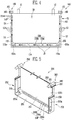
- FIG. 3A is a view showing one surface of the barrier of FIG. 2 .
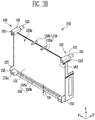
- FIG. 3B is a view showing the other surface of the barrier of FIG. 2 .
- FIG. 4 is a view schematically showing a front side of the barriers having the battery cell interposed therebetween.
- the spacing elements 155 may be provided at the lower portion of the barrier 150.
- the battery cell 10 is mounted or arranged on the spacing elements 155, and the flow path for the heat exchange medium may be provided between the spacing elements 155 and the battery cell 10.
- the spacing elements 155 may be formed in the shape of a box having a groove or hole 155a provided therein.
- Spacing members 154a and guidance plates 157 may be respectively interposed between the spacing elements 155 and the side plate 152 and between the spacing element 155 and the base plate 154.
- the spacing member 154a can be provided between the spacing elements 155 and the base plate 154 at a bottom of each of the spacing elements 155.
- the guidance plate 157 is preferably provided between the spacing element 155 and the side plate 152 at a side of the spacing element 155.
- the spacing member 154a may be provided to an inner surface 150a of the base plate 154, and the guidance member 157 may be provided to the outer surface 150b of the separation plate 151.
- the spacing member 154a may extend along the base plate 154 from the separation plate 151, and the guidance member 157 may extend along the side plate 152 from the separation plate 151.
- the inner surface 150a of any one barrier 150 (e.g., a first barrier) of the adjacent barriers 150 may face the outer surface 150b of the other barrier 150 (e.g., a second barrier) of the adjacent barriers 150 (see FIG. 2 ).
- the first and second barriers 150 refer to barriers 150 having the same shape, but for convenience of illustration, adjacent barriers 150 will be described as the first and second barriers 150.
- the spacing element 155 that is provided to the outer surface 150b of the second barrier 150 may be mounted on the spacing member 154a provided to the inner surface 150a of the first barrier 150.
- the guidance plate 157 provided to the outer surface 150b of the second barrier 150 may be provided to come in contact with the side plate 152 of the first barrier 150.
- the base plate 154 is provided to the inner surface 150a of the first barrier 150.
- the base plate 154 may hardly protrud from the outer surface 150b of the second barrier 150, or may not be provided to the outer surface 150b of the second barrier 150.
- the spacing element 155 provided to the outer surface 150b of the second barrier 150 may be spaced apart from a bottom end of the separation plate 151 at a predetermined distance.
- the predetermined distance may correspond to the sum of the thickness H1 of the spacing member 154a and the thickness H3 of the base plate 154.
- the sum of the thickness H2 of a lower first enforcement rib 156a described later and the thickness H1 of the spacing member 154a, on the inner surface 150a of the first barrier 150, may be provided to correspond to the thickness H4 of a lower first enforcement rib 156a provided to the outer surface 150b of the second barrier 150.
- the spacing element 155 provided to the outer surface 150b of the second barrier 150 may be mounted on the base plate 154 provided on the inner surface 150a of the first barrier 150.
- the spacing elements 155 respectively provided to the first and second barriers 150 may be aligned at positions corresponding to each other.
- the holes 155a provided inside the respective support portions 155 may be provided to face each other.
- the barrier 150 may further include an enforcement structure arranged between the spacing elements 155 (e.g., the first and second spacing elements 155) respectively provided at lower portions of the separation plate 151.
- the enforcement structure 156 may include a pair of first enforcement ribs 156a provided in parallel to the base plate 154 to respectively connect the first and second spacing elements 155 provided at upper and lower portions of the first and second spacing elements 155, and a plurality of second enforcement ribs 156b configured to vertically connect the pair of first enforcement ribs 156a.
- the bottom surface of the battery cell 10 may also be arranged on one of the first enforcement ribs 156a, and the one of the first enforcement ribs 156a can distribute the load of the battery cell 10 otherwise concentrated on the support portions 155.
- the second enforcement ribs 156b are arranged between the first enforcement ribs 156a, thereby reinforcing the strength of at least the one of the first enforcement ribs 156a.
- the first and second enforcement ribs 156a and 156b may be formed to have predetermined thicknesses.
- the first and second enforcement ribs 156a and 156b may be formed to have the same thickness.
- the first and second enforcement ribs 156a and 156b are connected to ach other, to be formed in the shape of a ladder with compartments between the enforcement ribs 156a, 156b.
- the first and second enforcement ribs 156a and 156b may form polygonaly and in particular rectangular or trapezoidal concave space portions.
- a width S2 of the spacing element 155 in a y-direction may be formed thicker than a width S3 of the first enforcement rib 156a in the y-direction, so that the spacing element 155 firmly supports the battery cell 10.
- the width S2 of the support portion 155 in the y-direction may be formed narrower than the width S1 of the base plate 154 except the first enforcement rib 156a in the y-direction, so that it is possible to increase the area of the flow path for the heat exchange medium that may pass along the bottom surface of the battery cell 10 and the base plate 154.
- the hole 155a in the spacing element 155 and the base plate 154 provided at the bottom of the spacing element 155 generate a differential pressure of the flowing heat exchange medium and change the path of the heat exchange medium, so that the heat exchange medium is ascended between the battery cell 10 and the side plate 152.
- the heat exchange medium passing along the lower portion of the battery cell 10 can be discharged to the outside of the barrier 150.
- the heat exchange path U1 extends into the barrier 150 through the openings 152a and 152b of the side plate 152 passes through the space between the battery cell 10 and the side plate 152, formed by the spacing rib 153 provided at the side plate 152 (heat exchange path U2). Subsequently, the heat exchange medium performs a heat exchange with the bottom surface of the battery cell 10 while passing through the space at the bottom surface of the battery cell 10, formed by the support portion 155 (heat exchange path U3), and then passes along a side surface of the battery cell 10 (heat exchange path U4). Thus, the heat exchange medium can be discharged to the outside of the barrier 150 by passing through the openings 152a and 152b of the side plate 152.
- FIGS. 5 and 6 Contents of these embodiments, except the following contents, are similar to those of the embodiment described with reference to FIGS. 1 to 4 , and therefore, their detailed descriptions will be omitted.
- FIG. 5 is a perspective view of a barrier according to another embodiment of the present invention.
- a barrier 250 may have one battery cell provided in the tray formed by the barrier 250 and a space that opens towards the tray and is formed by an adjacent barrier 250.
- each barrier 250 is provided with a fastening member 260, so that the barriers 250 can be fastened and fixed to each other through the fastening portions 260.
- the adjacent barrier 250 and the battery cell are provided to be spaced apart from each other, and the space between the adjacent barrier 250 and the battery cell may act as a flow path of the heat exchange medium.
- the barrier 250 may include a separation plate 251 interposed between the two adjacent battery cells, and side plates 252 and a base plate 254 respectively provided at end portions or edges of the separation plate 251 to support side and bottom surfaces of the battery cell.
- the barrier 250 may be provided so that the configuration provided to one surface of the separation plate 251 is different from that provided to the other surface opposite to the one surface of the separation plate 251.
- the side plates 252 and the base plate 254 may be provided to and in particular protrude from the one surface of the separation plate 251.
- the side plates 252 and the base plate 254 may not be provided to and in particular not project from the other surface of the separation plate 251.
- Each of the side plates 252 may be provided with openings 252a and 252b which are passages through which the heat exchange medium can flow in the barrier 250 or flow out of the barrier 250, and spacing ribs 253 that protrude from a surface of the side plate 252.
- a body portion 261 of the fastening member 260 may be provided at a portion where a top portion of the side plate 252 and the separation plate 251 meet each other.
- a fastening receptacle 262 and a fastening protrusion 263 may be respectively provided at one end and the other end of the body portion 261 of the fastening member 260.
- Spacing elements 255 configured to support the battery cell may be provided beneath the separation plate 251, e.g. at the lower edge of the separation plate 251 and extending in or against a stacking direction, in which the barrier 250 can be attached to each other.
- the spacing elements 255 may be respectively provided at one side and the other side of the separation plate 251.
- the spacing elements 255 respectively provided at the one side and the other side of the separation plate 251 may be interconnected by an enforcement structure 256.
- An upper first enforcement rib 256a of the enforcement structure 256 is provided to interconnect upper portions of the spacing elements 255, and a lower first enforcement rib 256c of enforcement structure 256 is provided to interconnect lower portions of the spacing elements 255.
- the first enforcement ribs 256a and 256c can support, together with the support portions 255, the bottom surface of the battery cell 10.
- the pair of first enforcement ribs 256a and 256c provided in parallel to each other may be interconnected by a plurality of second enforcement ribs 256b provided vertically, i.e. perpendicular to the first enforcement ribs 256a and 256c.
- the thickness of the first enforcement ribs 256a and 256c may be formed constant without any change in thickness, and the second enforcement ribs 256b may be formed to have a continuously changing thickness. That is, the thickness of the second enforcement rib 256b may gradually decrease as the second enforcement rib 256b reaches from the lower first enforcement rib 256c to the upper first enforcement rib 256a.
- the spacing element 255 is formed in the shape of a quadrangular box having a groove, opening or hole 255a therein.
- the groove, opening or hole 255a may be formed with a trapezoidal shape.
- the spacing element 255 and the enforcement structure 256 can support the load of the battery cell.
- the lower portion of the spacing element 255 and the lower portion of the second enforcement rib 256b are formed thicker than upper portions, so that it is possible to improve the strength of the spacing element 255 and the enforcement structure 256. Accordingly, the load of the battery cell can be more efficiently supported.
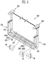
- FIG. 6 is a perspective view of a barrier according to still another embodiment of the present invention.
- a barrier 350 may be interposed between adjacent battery cells in the battery module.
- the barrier 350 may include a separation plate 351 provided to face a wide surface of the battery cell, and side plate 352 and a base plate 354, provided to face narrow surfaces (side and bottom surfaces) of the battery cell at each edge or corner of the separation plate 351.
- the base plate 354 may include two spacing elements 355 configured to support the battery cell, and an enforcement structure 356 configured to connect the two spacing elements 355 to each other.
- Each of the spacing elements 355 may be formed in the shape of a box having a groove, opening or hole 355a therein.
- the enforcement structure 356 may include a pair of first enforcement ribs 356a provided in parallel to connect the two spacing elements 255 to each other, and second enforcement ribs 356b configured to interconnect the pair of first enforcement ribs 356a to each other.
- the base plate 354 may be further provided with a spacing member 354a on which the spacign element 355 is mounted.
- the barrier 350 may be provided with one or more guide bars 357 provided to the base plate 354 so as to guide the flow of a heat exchange medium.
- Each of the guide bars 357 protrudes toward the bottom surface of the battery cell on the base plate 354.
- the guide bar 357 may extend along the length direction of the base plate 354.
- the guide bar 354 may be provided so that the corner of the guide bar 354 is rounded.
- the cross-section of the guide bar 354 in a direction vertical or perpendicular to the extending direction of the guide bar 354 may be formed in a semicircular shape.
- a height R1 of the guide bar 354 may be formed equal to or smaller than a thickness H2 of a lower first enforcement rib 356a of the first enforcement ribs 356a or the thickness H1 of the spacing element 354a.
- a flow path of the heat exchange medium after is has exchanged heat with the battery cell may be provided in the barrier 350 according to this embodiment.
- the flow path of the heat exchange medium may also be provided between the base plate 354 and the bottom surface of the battery cell.
- the guide bar 357 is provided on the base plate 354, so that the flow of the heat exchange medium can be guided, to thereby improve the heat exchange efficiency between the heat exchange medium and the battery cell.
- the guide bar 357 guides only the flow of the heat exchange medium but does not interfere with the flow of the heat exchange medium in the width direction of the base plate 354, i.e. perpendicular to the separation plate 351.
Landscapes
- Chemical & Material Sciences (AREA)
- Chemical Kinetics & Catalysis (AREA)
- Electrochemistry (AREA)
- General Chemical & Material Sciences (AREA)
- Engineering & Computer Science (AREA)
- Manufacturing & Machinery (AREA)
- Secondary Cells (AREA)
- Battery Mounting, Suspending (AREA)
Claims (13)
- Barriere (150) zum Trennen von zwei benachbarten Batteriezellen (10) eines Batteriemoduls (100) voneinander, wobei die Barriere (150) eine Trennungsplatte (151), zumindest eine Seitenplatte (152) und eine Basisplatte (154) aufweist, wobei die Seitenplatte (152) und die Basisplatte (154) auf benachbarten Rändern der Trennungsplatte (151) ruhen, wodurch sie ein Fach zum Aufnehmen einer Batteriezelle (10) definieren, sowie ein Abstandselement (155), das von der Basisplatte (154) in das Fach hinein ragt, wobei das Abstandselement (155) von der Basisplatte (154) in eine Richtung (z) perpendikulär zur Basisplatte (154) vorsteht und die Seitenplatte (152) mit einer Öffnung (152a) ausgebildet ist, dadurch gekennzeichnet, dass eine Höhe des Abstandselements (155) in der Richtung (z) perpendikulär zur Basisplatte (154) größer als ein Abstand zwischen der Öffnung (152a) und der Basisplatte (154) ist.
- Barriere (150) nach Anspruch 1, dadurch gekennzeichnet, dass sich eine Nut (155a) in das Abstandselement (155) hinein erstreckt.
- Barriere (150) nach Anspruch 1 oder 2, dadurch gekennzeichnet, dass sich das Abstandselement (155) über eine Seite (150b) der Trennungsplatte (151), die dem Fach gegenüberliegt, hinaus erstreckt, wobei eine Führungsplatte (157) bereitgestellt wird, die sich parallel zur Seitenplatte (152) und dem Abstandselement (155) erstreckt und an diesen anliegt, wobei die Führungsplatte (157) das Abstandselement (155) von der Basisplatte (154) weg überragt.
- Barriere (150) nach einem der Ansprüche 1 bis 3, dadurch gekennzeichnet, dass die Seitenplatte (152) einen ersten und einen zweiten Abschnitt aufweist, wobei sich der erste Abschnitt weiter von der Trennungsplatte (151) als der zweite Abschnitt erstreckt, wobei der erste Abschnitt zwischen dem zweiten Abschnitt und der Basisplatte (154) angeordnet ist.
- Barriere (150) nach einem der Ansprüche 1 bis 4, dadurch gekennzeichnet, dass die Seitenplatte (152) mit einer Innenseite, die dem Fach zugewandt ist, und einer Außenseite, die vom Fach abgewandt ist, ausgebildet ist, wobei zumindest eine Abstandsrippe (153) auf der Innenseite und/oder der Außenseite angeordnet ist.
- Barriere (150) nach einem der Ansprüche 1 bis 5, dadurch gekennzeichnet, dass zwei Seitenplatten (152) und zwei Abstandselemente (155) bereitgestellt werden, wobei die Seitenplatten (152) an gegenüberliegenden Rändern der Trennungsplatte (151) angeordnet sind und jedes der Abstandselemente (155) benachbart zu einer der Seitenplatten (152) angeordnet ist.
- Barriere (150) nach einem der Ansprüche 1 bis 6, dadurch gekennzeichnet, dass die Trennungsplatte (151) einen Randabschnitt, der an der Basisplatte (154) anliegt, aufweist, wobei der Randabschnitt Verstärkungsrippen (156a, 156b) aufweist.
- Barriere (350) nach einem der Ansprüche 1 bis 7, dadurch gekennzeichnet, dass zumindest eine Führungsrippe (357) von der Basisplatte (154) in das Fach hinein ragt.
- Barriere (150) nach einem der Ansprüche 1 bis 8, gekennzeichnet durch ein Befestigungselement (160), das angepasst ist, um die Barriere (150) durch einen Kraftschluss unverlierbar an einer weiteren Barriere (150) zu befestigen.
- Barriere (150) nach Anspruch 9, dadurch gekennzeichnet, dass das Befestigungselement (160) eine Befestigungsaufnahme (162) und einen Befestigungsvorsprung (163) aufweist, wobei sich die Befestigungsaufnahme (162) gegen eine Montagerichtung öffnet und sich der Befestigungsvorsprung (163) in eine Montagerichtung erstreckt, wobei die Barriere (150) an einer weiteren Barriere (150) angebracht sein kann, wobei die Befestigungsaufnahme (162) angepasst ist, um zumindest abschnittweise den Befestigungsvorsprung (163) der weiteren Barriere (150) kraftschlüssig aufzunehmen.
- Barriere (150) nach einem der Ansprüche 1 bis 10, dadurch gekennzeichnet, dass die Barriere (150) zumindest eine Haltelasche (159a), die von einem Rand der und perpendikulär zur Trennungsplatte (151) vorsteht, aufweist, wobei der Rand der Basisplatte (154) gegenüberliegt.
- Batteriemodul (100) mit einer Vielzahl von Batteriezellen (10), die hintereinander in einer Stapelrichtung angeordnet sind, wobei das Batteriemodul (100) eine Barriere (150), die zwischen zwei benachbarten Batteriezellen (10) der Vielzahl der Batteriezellen (10) positioniert ist, aufweist, dadurch gekennzeichnet, dass die Barriere (150) eine Barriere (150) nach einem der Ansprüche 1 bis 11 ist.
- Batteriemodul (100) nach Anspruch 12, dadurch gekennzeichnet, dass die Batteriezelle (10) im Fach angeordnet ist und an den zwei Abstandselementen (155) anliegt, wobei drei Wärmeaustauschpfade (U2, U3, U4) zwischen der Batteriezelle (10) und der Barriere (150) definiert sind, wobei die drei Wärmeaustauschpfade (U2, U3, U4) im Bereich der Abstandselemente (155) miteinander verbunden sind.
Applications Claiming Priority (2)
| Application Number | Priority Date | Filing Date | Title |
|---|---|---|---|
| US201361862202P | 2013-08-05 | 2013-08-05 | |
| US14/328,445 US9484607B2 (en) | 2013-08-05 | 2014-07-10 | Battery module |
Publications (3)
| Publication Number | Publication Date |
|---|---|
| EP2835842A2 EP2835842A2 (de) | 2015-02-11 |
| EP2835842A3 EP2835842A3 (de) | 2015-03-18 |
| EP2835842B1 true EP2835842B1 (de) | 2019-06-26 |
Family
ID=51292819
Family Applications (1)
| Application Number | Title | Priority Date | Filing Date |
|---|---|---|---|
| EP14179799.3A Active EP2835842B1 (de) | 2013-08-05 | 2014-08-05 | Batteriemodul |
Country Status (5)
| Country | Link |
|---|---|
| US (1) | US9484607B2 (de) |
| EP (1) | EP2835842B1 (de) |
| JP (1) | JP6564562B2 (de) |
| KR (1) | KR102257682B1 (de) |
| CN (1) | CN104347890B (de) |
Families Citing this family (10)
| Publication number | Priority date | Publication date | Assignee | Title |
|---|---|---|---|---|
| CN105322214B (zh) | 2014-07-30 | 2019-08-09 | 株式会社杰士汤浅国际 | 蓄电装置 |
| US9356270B2 (en) * | 2014-08-20 | 2016-05-31 | Ford Global Technologies, Llc | Multi-tier traction battery assembly with alignment feature |
| CN107851757B (zh) * | 2015-07-30 | 2020-11-13 | 三洋电机株式会社 | 电源装置与包括该电源装置的电源系统及电池单元用分隔件 |
| JP6390549B2 (ja) | 2015-08-07 | 2018-09-19 | 株式会社デンソー | 電池パック |
| KR101826141B1 (ko) | 2015-08-28 | 2018-02-06 | 삼성에스디아이 주식회사 | 이차 전지 팩 |
| JP6603536B2 (ja) * | 2015-10-19 | 2019-11-06 | 株式会社Gsユアサ | 蓄電装置 |
| JP2017216087A (ja) * | 2016-05-30 | 2017-12-07 | 株式会社東芝 | 組電池 |
| US20220013836A1 (en) * | 2018-11-27 | 2022-01-13 | Amogreentech Co., Ltd. | Pouch type battery cartridge and pouch type battery pack comprising same |
| DE102019210193A1 (de) * | 2019-07-10 | 2021-01-14 | Mahle International Gmbh | Energiespeichermodul |
| IT202300022692A1 (it) * | 2023-10-30 | 2025-04-30 | Fiat Ricerche | "gruppo di batteria elettrica con sistema termoregolatore ad elevata efficienza" |
Family Cites Families (15)
| Publication number | Priority date | Publication date | Assignee | Title |
|---|---|---|---|---|
| JP2006073461A (ja) * | 2004-09-06 | 2006-03-16 | Toyota Motor Corp | 組電池 |
| JP2007048750A (ja) * | 2005-08-10 | 2007-02-22 | Samsung Sdi Co Ltd | 電池モジュール |
| JP5118817B2 (ja) * | 2006-04-11 | 2013-01-16 | トヨタ自動車株式会社 | 2次電池の保持構造 |
| JP2009231143A (ja) * | 2008-03-24 | 2009-10-08 | Toshiba Corp | 電池装置 |
| JP5465440B2 (ja) * | 2009-01-28 | 2014-04-09 | 三洋電機株式会社 | 組電池 |
| WO2010131700A1 (ja) * | 2009-05-14 | 2010-11-18 | 株式会社Gsユアサ | 組電池 |
| JP5528746B2 (ja) | 2009-09-11 | 2014-06-25 | 三洋電機株式会社 | 組電池 |
| US9172068B2 (en) * | 2009-10-22 | 2015-10-27 | Samsung Sdi Co., Ltd. | Battery pack |
| KR101205180B1 (ko) * | 2010-05-18 | 2012-11-27 | 주식회사 엘지화학 | 콤팩트하고 안정성이 우수한 냉각부재와 이를 포함하는 전지모듈 |
| US9793584B2 (en) * | 2011-06-10 | 2017-10-17 | Samsung Sdi Co., Ltd. | Battery module |
| DE102011104499A1 (de) | 2011-06-17 | 2012-12-20 | Audi Ag | Batterie für ein Fahrzeug |
| KR101262974B1 (ko) | 2011-07-21 | 2013-05-08 | 기아자동차주식회사 | 배터리팩용 냉각케이스 |
| KR101282519B1 (ko) | 2011-08-02 | 2013-07-04 | 로베르트 보쉬 게엠베하 | 배터리 모듈 |
| US9240580B2 (en) * | 2012-05-24 | 2016-01-19 | Samsung Sdi Co., Ltd. | Battery module |
| JP6287384B2 (ja) * | 2013-04-08 | 2018-03-07 | 株式会社Gsユアサ | 蓄電装置 |
-
2014
- 2014-07-10 US US14/328,445 patent/US9484607B2/en active Active
- 2014-07-18 KR KR1020140090951A patent/KR102257682B1/ko active Active
- 2014-08-05 CN CN201410384465.1A patent/CN104347890B/zh active Active
- 2014-08-05 JP JP2014159567A patent/JP6564562B2/ja active Active
- 2014-08-05 EP EP14179799.3A patent/EP2835842B1/de active Active
Non-Patent Citations (1)
| Title |
|---|
| None * |
Also Published As
| Publication number | Publication date |
|---|---|
| JP2015032586A (ja) | 2015-02-16 |
| JP6564562B2 (ja) | 2019-08-21 |
| US9484607B2 (en) | 2016-11-01 |
| CN104347890B (zh) | 2019-11-19 |
| US20150037631A1 (en) | 2015-02-05 |
| EP2835842A2 (de) | 2015-02-11 |
| KR20150016895A (ko) | 2015-02-13 |
| KR102257682B1 (ko) | 2021-05-28 |
| CN104347890A (zh) | 2015-02-11 |
| EP2835842A3 (de) | 2015-03-18 |
Similar Documents
| Publication | Publication Date | Title |
|---|---|---|
| EP2835842B1 (de) | Batteriemodul | |
| JP6744435B2 (ja) | 電池サブモジュールキャリア、電池サブモジュール、電池システムおよび自動車 | |
| JP7033235B2 (ja) | 冷却部材を備えるバッテリーモジュール、バッテリーパック、及び電力貯蔵装置 | |
| EP3062361B1 (de) | Sekundärbatterierahmen und batteriemodul, das diesen enthält | |
| EP3984865B1 (de) | Unterboden für ein fahrzeug | |
| JP6795710B2 (ja) | セルエッジ直接冷却方式のバッテリーモジュール及びそれを含むバッテリーパック | |
| EP2808936B1 (de) | Batteriepack | |
| EP1091438B1 (de) | Batteriesatz | |
| EP2533350B1 (de) | Batteriemodul mit verbessertem Wärmeaustausch | |
| KR102045528B1 (ko) | 배터리 모듈 | |
| KR20180113419A (ko) | 루버 핀 형상의 열전도 매개체를 구비한 배터리 팩 | |
| KR20190064887A (ko) | 방열 플레이트를 구비한 배터리 모듈 | |
| KR20150094030A (ko) | 배터리 팩 | |
| US20220285759A1 (en) | Battery Module and Battery Pack Including the Same | |
| JP2016103378A (ja) | 組電池 | |
| CN207441810U (zh) | 电池模组及电池包 | |
| KR20240012314A (ko) | 배터리 팩 및 이를 포함하는 자동차 | |
| KR102683482B1 (ko) | 전지 팩 | |
| KR20240046898A (ko) | 전지, 전기기기, 전지를 제조하기 위한 방법 및 장비 | |
| EP4439797A2 (de) | Batteriemodulbaugruppe | |
| CN221327934U (zh) | 电池包箱体和电池包 | |
| KR102926474B1 (ko) | 배터리 팩 및 이를 포함하는 차량 | |
| JP7709285B2 (ja) | バッテリパック | |
| EP4471941B1 (de) | Doppelseitig gekühltes batteriemodul und darin enthaltener kühlkörper | |
| JP2020119884A (ja) | 蓄電スタックの冷却構造および蓄電スタックの冷却システム |
Legal Events
| Date | Code | Title | Description |
|---|---|---|---|
| PUAI | Public reference made under article 153(3) epc to a published international application that has entered the european phase |
Free format text: ORIGINAL CODE: 0009012 |
|
| 17P | Request for examination filed |
Effective date: 20140805 |
|
| AK | Designated contracting states |
Kind code of ref document: A2 Designated state(s): AL AT BE BG CH CY CZ DE DK EE ES FI FR GB GR HR HU IE IS IT LI LT LU LV MC MK MT NL NO PL PT RO RS SE SI SK SM TR |
|
| AX | Request for extension of the european patent |
Extension state: BA ME |
|
| PUAL | Search report despatched |
Free format text: ORIGINAL CODE: 0009013 |
|
| AK | Designated contracting states |
Kind code of ref document: A3 Designated state(s): AL AT BE BG CH CY CZ DE DK EE ES FI FR GB GR HR HU IE IS IT LI LT LU LV MC MK MT NL NO PL PT RO RS SE SI SK SM TR |
|
| AX | Request for extension of the european patent |
Extension state: BA ME |
|
| RIC1 | Information provided on ipc code assigned before grant |
Ipc: H01M 10/6557 20140101ALI20150210BHEP Ipc: H01M 10/613 20140101ALI20150210BHEP Ipc: H01M 2/10 20060101AFI20150210BHEP |
|
| R17P | Request for examination filed (corrected) |
Effective date: 20150917 |
|
| RBV | Designated contracting states (corrected) |
Designated state(s): AL AT BE BG CH CY CZ DE DK EE ES FI FR GB GR HR HU IE IS IT LI LT LU LV MC MK MT NL NO PL PT RO RS SE SI SK SM TR |
|
| STAA | Information on the status of an ep patent application or granted ep patent |
Free format text: STATUS: EXAMINATION IS IN PROGRESS |
|
| 17Q | First examination report despatched |
Effective date: 20161031 |
|
| REG | Reference to a national code |
Ref country code: DE Ref legal event code: R079 Ref document number: 602014048987 Country of ref document: DE Free format text: PREVIOUS MAIN CLASS: H01M0002100000 Ipc: H01M0002140000 |
|
| RIC1 | Information provided on ipc code assigned before grant |
Ipc: H01M 10/6557 20140101ALI20181129BHEP Ipc: H01M 10/656 20140101ALI20181129BHEP Ipc: H01M 10/647 20140101ALI20181129BHEP Ipc: H01M 2/10 20060101ALI20181129BHEP Ipc: H01M 10/625 20140101ALI20181129BHEP Ipc: H01M 10/613 20140101ALI20181129BHEP Ipc: H01M 2/14 20060101AFI20181129BHEP |
|
| GRAP | Despatch of communication of intention to grant a patent |
Free format text: ORIGINAL CODE: EPIDOSNIGR1 |
|
| STAA | Information on the status of an ep patent application or granted ep patent |
Free format text: STATUS: GRANT OF PATENT IS INTENDED |
|
| INTG | Intention to grant announced |
Effective date: 20190110 |
|
| GRAS | Grant fee paid |
Free format text: ORIGINAL CODE: EPIDOSNIGR3 |
|
| GRAA | (expected) grant |
Free format text: ORIGINAL CODE: 0009210 |
|
| STAA | Information on the status of an ep patent application or granted ep patent |
Free format text: STATUS: THE PATENT HAS BEEN GRANTED |
|
| AK | Designated contracting states |
Kind code of ref document: B1 Designated state(s): AL AT BE BG CH CY CZ DE DK EE ES FI FR GB GR HR HU IE IS IT LI LT LU LV MC MK MT NL NO PL PT RO RS SE SI SK SM TR |
|
| REG | Reference to a national code |
Ref country code: GB Ref legal event code: FG4D |
|
| REG | Reference to a national code |
Ref country code: CH Ref legal event code: EP |
|
| REG | Reference to a national code |
Ref country code: AT Ref legal event code: REF Ref document number: 1149334 Country of ref document: AT Kind code of ref document: T Effective date: 20190715 |
|
| REG | Reference to a national code |
Ref country code: IE Ref legal event code: FG4D |
|
| REG | Reference to a national code |
Ref country code: DE Ref legal event code: R096 Ref document number: 602014048987 Country of ref document: DE |
|
| REG | Reference to a national code |
Ref country code: NL Ref legal event code: MP Effective date: 20190626 |
|
| PG25 | Lapsed in a contracting state [announced via postgrant information from national office to epo] |
Ref country code: NO Free format text: LAPSE BECAUSE OF FAILURE TO SUBMIT A TRANSLATION OF THE DESCRIPTION OR TO PAY THE FEE WITHIN THE PRESCRIBED TIME-LIMIT Effective date: 20190926 Ref country code: AL Free format text: LAPSE BECAUSE OF FAILURE TO SUBMIT A TRANSLATION OF THE DESCRIPTION OR TO PAY THE FEE WITHIN THE PRESCRIBED TIME-LIMIT Effective date: 20190626 Ref country code: SE Free format text: LAPSE BECAUSE OF FAILURE TO SUBMIT A TRANSLATION OF THE DESCRIPTION OR TO PAY THE FEE WITHIN THE PRESCRIBED TIME-LIMIT Effective date: 20190626 Ref country code: FI Free format text: LAPSE BECAUSE OF FAILURE TO SUBMIT A TRANSLATION OF THE DESCRIPTION OR TO PAY THE FEE WITHIN THE PRESCRIBED TIME-LIMIT Effective date: 20190626 Ref country code: LT Free format text: LAPSE BECAUSE OF FAILURE TO SUBMIT A TRANSLATION OF THE DESCRIPTION OR TO PAY THE FEE WITHIN THE PRESCRIBED TIME-LIMIT Effective date: 20190626 Ref country code: HR Free format text: LAPSE BECAUSE OF FAILURE TO SUBMIT A TRANSLATION OF THE DESCRIPTION OR TO PAY THE FEE WITHIN THE PRESCRIBED TIME-LIMIT Effective date: 20190626 |
|
| REG | Reference to a national code |
Ref country code: LT Ref legal event code: MG4D |
|
| PG25 | Lapsed in a contracting state [announced via postgrant information from national office to epo] |
Ref country code: LV Free format text: LAPSE BECAUSE OF FAILURE TO SUBMIT A TRANSLATION OF THE DESCRIPTION OR TO PAY THE FEE WITHIN THE PRESCRIBED TIME-LIMIT Effective date: 20190626 Ref country code: RS Free format text: LAPSE BECAUSE OF FAILURE TO SUBMIT A TRANSLATION OF THE DESCRIPTION OR TO PAY THE FEE WITHIN THE PRESCRIBED TIME-LIMIT Effective date: 20190626 Ref country code: BG Free format text: LAPSE BECAUSE OF FAILURE TO SUBMIT A TRANSLATION OF THE DESCRIPTION OR TO PAY THE FEE WITHIN THE PRESCRIBED TIME-LIMIT Effective date: 20190926 Ref country code: GR Free format text: LAPSE BECAUSE OF FAILURE TO SUBMIT A TRANSLATION OF THE DESCRIPTION OR TO PAY THE FEE WITHIN THE PRESCRIBED TIME-LIMIT Effective date: 20190927 |
|
| REG | Reference to a national code |
Ref country code: AT Ref legal event code: MK05 Ref document number: 1149334 Country of ref document: AT Kind code of ref document: T Effective date: 20190626 |
|
| PG25 | Lapsed in a contracting state [announced via postgrant information from national office to epo] |
Ref country code: PT Free format text: LAPSE BECAUSE OF FAILURE TO SUBMIT A TRANSLATION OF THE DESCRIPTION OR TO PAY THE FEE WITHIN THE PRESCRIBED TIME-LIMIT Effective date: 20191028 Ref country code: CZ Free format text: LAPSE BECAUSE OF FAILURE TO SUBMIT A TRANSLATION OF THE DESCRIPTION OR TO PAY THE FEE WITHIN THE PRESCRIBED TIME-LIMIT Effective date: 20190626 Ref country code: AT Free format text: LAPSE BECAUSE OF FAILURE TO SUBMIT A TRANSLATION OF THE DESCRIPTION OR TO PAY THE FEE WITHIN THE PRESCRIBED TIME-LIMIT Effective date: 20190626 Ref country code: EE Free format text: LAPSE BECAUSE OF FAILURE TO SUBMIT A TRANSLATION OF THE DESCRIPTION OR TO PAY THE FEE WITHIN THE PRESCRIBED TIME-LIMIT Effective date: 20190626 Ref country code: SK Free format text: LAPSE BECAUSE OF FAILURE TO SUBMIT A TRANSLATION OF THE DESCRIPTION OR TO PAY THE FEE WITHIN THE PRESCRIBED TIME-LIMIT Effective date: 20190626 Ref country code: RO Free format text: LAPSE BECAUSE OF FAILURE TO SUBMIT A TRANSLATION OF THE DESCRIPTION OR TO PAY THE FEE WITHIN THE PRESCRIBED TIME-LIMIT Effective date: 20190626 Ref country code: NL Free format text: LAPSE BECAUSE OF FAILURE TO SUBMIT A TRANSLATION OF THE DESCRIPTION OR TO PAY THE FEE WITHIN THE PRESCRIBED TIME-LIMIT Effective date: 20190626 |
|
| PG25 | Lapsed in a contracting state [announced via postgrant information from national office to epo] |
Ref country code: IT Free format text: LAPSE BECAUSE OF FAILURE TO SUBMIT A TRANSLATION OF THE DESCRIPTION OR TO PAY THE FEE WITHIN THE PRESCRIBED TIME-LIMIT Effective date: 20190626 Ref country code: IS Free format text: LAPSE BECAUSE OF FAILURE TO SUBMIT A TRANSLATION OF THE DESCRIPTION OR TO PAY THE FEE WITHIN THE PRESCRIBED TIME-LIMIT Effective date: 20191026 Ref country code: SM Free format text: LAPSE BECAUSE OF FAILURE TO SUBMIT A TRANSLATION OF THE DESCRIPTION OR TO PAY THE FEE WITHIN THE PRESCRIBED TIME-LIMIT Effective date: 20190626 Ref country code: ES Free format text: LAPSE BECAUSE OF FAILURE TO SUBMIT A TRANSLATION OF THE DESCRIPTION OR TO PAY THE FEE WITHIN THE PRESCRIBED TIME-LIMIT Effective date: 20190626 |
|
| PG25 | Lapsed in a contracting state [announced via postgrant information from national office to epo] |
Ref country code: TR Free format text: LAPSE BECAUSE OF FAILURE TO SUBMIT A TRANSLATION OF THE DESCRIPTION OR TO PAY THE FEE WITHIN THE PRESCRIBED TIME-LIMIT Effective date: 20190626 |
|
| PG25 | Lapsed in a contracting state [announced via postgrant information from national office to epo] |
Ref country code: PL Free format text: LAPSE BECAUSE OF FAILURE TO SUBMIT A TRANSLATION OF THE DESCRIPTION OR TO PAY THE FEE WITHIN THE PRESCRIBED TIME-LIMIT Effective date: 20190626 Ref country code: DK Free format text: LAPSE BECAUSE OF FAILURE TO SUBMIT A TRANSLATION OF THE DESCRIPTION OR TO PAY THE FEE WITHIN THE PRESCRIBED TIME-LIMIT Effective date: 20190626 |
|
| PG25 | Lapsed in a contracting state [announced via postgrant information from national office to epo] |
Ref country code: MC Free format text: LAPSE BECAUSE OF FAILURE TO SUBMIT A TRANSLATION OF THE DESCRIPTION OR TO PAY THE FEE WITHIN THE PRESCRIBED TIME-LIMIT Effective date: 20190626 Ref country code: IS Free format text: LAPSE BECAUSE OF FAILURE TO SUBMIT A TRANSLATION OF THE DESCRIPTION OR TO PAY THE FEE WITHIN THE PRESCRIBED TIME-LIMIT Effective date: 20200224 Ref country code: CH Free format text: LAPSE BECAUSE OF NON-PAYMENT OF DUE FEES Effective date: 20190831 Ref country code: LI Free format text: LAPSE BECAUSE OF NON-PAYMENT OF DUE FEES Effective date: 20190831 Ref country code: LU Free format text: LAPSE BECAUSE OF NON-PAYMENT OF DUE FEES Effective date: 20190805 |
|
| REG | Reference to a national code |
Ref country code: BE Ref legal event code: MM Effective date: 20190831 |
|
| REG | Reference to a national code |
Ref country code: DE Ref legal event code: R097 Ref document number: 602014048987 Country of ref document: DE |
|
| PLBE | No opposition filed within time limit |
Free format text: ORIGINAL CODE: 0009261 |
|
| STAA | Information on the status of an ep patent application or granted ep patent |
Free format text: STATUS: NO OPPOSITION FILED WITHIN TIME LIMIT |
|
| PG2D | Information on lapse in contracting state deleted |
Ref country code: IS |
|
| PG25 | Lapsed in a contracting state [announced via postgrant information from national office to epo] |
Ref country code: IE Free format text: LAPSE BECAUSE OF NON-PAYMENT OF DUE FEES Effective date: 20190805 |
|
| 26N | No opposition filed |
Effective date: 20200603 |
|
| PG25 | Lapsed in a contracting state [announced via postgrant information from national office to epo] |
Ref country code: BE Free format text: LAPSE BECAUSE OF NON-PAYMENT OF DUE FEES Effective date: 20190831 Ref country code: SI Free format text: LAPSE BECAUSE OF FAILURE TO SUBMIT A TRANSLATION OF THE DESCRIPTION OR TO PAY THE FEE WITHIN THE PRESCRIBED TIME-LIMIT Effective date: 20190626 |
|
| REG | Reference to a national code |
Ref country code: DE Ref legal event code: R079 Ref document number: 602014048987 Country of ref document: DE Free format text: PREVIOUS MAIN CLASS: H01M0002140000 Ipc: H01M0050400000 |
|
| PG25 | Lapsed in a contracting state [announced via postgrant information from national office to epo] |
Ref country code: CY Free format text: LAPSE BECAUSE OF FAILURE TO SUBMIT A TRANSLATION OF THE DESCRIPTION OR TO PAY THE FEE WITHIN THE PRESCRIBED TIME-LIMIT Effective date: 20190626 |
|
| PG25 | Lapsed in a contracting state [announced via postgrant information from national office to epo] |
Ref country code: HU Free format text: LAPSE BECAUSE OF FAILURE TO SUBMIT A TRANSLATION OF THE DESCRIPTION OR TO PAY THE FEE WITHIN THE PRESCRIBED TIME-LIMIT; INVALID AB INITIO Effective date: 20140805 Ref country code: MT Free format text: LAPSE BECAUSE OF FAILURE TO SUBMIT A TRANSLATION OF THE DESCRIPTION OR TO PAY THE FEE WITHIN THE PRESCRIBED TIME-LIMIT Effective date: 20190626 |
|
| PG25 | Lapsed in a contracting state [announced via postgrant information from national office to epo] |
Ref country code: MK Free format text: LAPSE BECAUSE OF FAILURE TO SUBMIT A TRANSLATION OF THE DESCRIPTION OR TO PAY THE FEE WITHIN THE PRESCRIBED TIME-LIMIT Effective date: 20190626 |
|
| P01 | Opt-out of the competence of the unified patent court (upc) registered |
Effective date: 20230528 |
|
| PGFP | Annual fee paid to national office [announced via postgrant information from national office to epo] |
Ref country code: DE Payment date: 20250805 Year of fee payment: 12 |
|
| PGFP | Annual fee paid to national office [announced via postgrant information from national office to epo] |
Ref country code: GB Payment date: 20250731 Year of fee payment: 12 |
|
| PGFP | Annual fee paid to national office [announced via postgrant information from national office to epo] |
Ref country code: FR Payment date: 20250808 Year of fee payment: 12 |