EP2837353A1 - Antrieb und Zusatzvorrichtung für Ultraschall-Reinigungsgeräte - Google Patents
Antrieb und Zusatzvorrichtung für Ultraschall-Reinigungsgeräte Download PDFInfo
- Publication number
- EP2837353A1 EP2837353A1 EP20130199128 EP13199128A EP2837353A1 EP 2837353 A1 EP2837353 A1 EP 2837353A1 EP 20130199128 EP20130199128 EP 20130199128 EP 13199128 A EP13199128 A EP 13199128A EP 2837353 A1 EP2837353 A1 EP 2837353A1
- Authority
- EP
- European Patent Office
- Prior art keywords
- coupling element
- medical instrument
- movement
- adapter
- instrument
- Prior art date
- Legal status (The legal status is an assumption and is not a legal conclusion. Google has not performed a legal analysis and makes no representation as to the accuracy of the status listed.)
- Granted
Links
Images





Classifications
-
- B—PERFORMING OPERATIONS; TRANSPORTING
- B08—CLEANING
- B08B—CLEANING IN GENERAL; PREVENTION OF FOULING IN GENERAL
- B08B3/00—Cleaning by methods involving the use or presence of liquid or steam
- B08B3/04—Cleaning involving contact with liquid
- B08B3/10—Cleaning involving contact with liquid with additional treatment of the liquid or of the object being cleaned, e.g. by heat, by electricity or by vibration
- B08B3/12—Cleaning involving contact with liquid with additional treatment of the liquid or of the object being cleaned, e.g. by heat, by electricity or by vibration by sonic or ultrasonic vibrations
-
- A—HUMAN NECESSITIES
- A61—MEDICAL OR VETERINARY SCIENCE; HYGIENE
- A61B—DIAGNOSIS; SURGERY; IDENTIFICATION
- A61B90/00—Instruments, implements or accessories specially adapted for surgery or diagnosis and not covered by any of the groups A61B1/00 - A61B50/00, e.g. for luxation treatment or for protecting wound edges
- A61B90/70—Cleaning devices specially adapted for surgical instruments
-
- A—HUMAN NECESSITIES
- A61—MEDICAL OR VETERINARY SCIENCE; HYGIENE
- A61B—DIAGNOSIS; SURGERY; IDENTIFICATION
- A61B34/00—Computer-aided surgery; Manipulators or robots specially adapted for use in surgery
- A61B34/30—Surgical robots
Definitions
- the invention relates to an additional device for an ultrasound device or an ultrasound cleaning device, a control and / or operating device for an ultrasound device with such an additional device, and a method for actively moving at least a portion of a medical instrument in an ultrasonic cleaning device.
- surgical instruments are placed in a basket and then introduced into a tub filled with a liquid of an ultrasonic cleaning device. Subsequently, the tub is subjected to ultrasound, so that foreign particles and adhesions in a short time to be able to solve.
- this process is supported by the addition of suitable cleaning and / or disinfecting preparations which are added to the liquid.
- the object is achieved according to a drive according to the features of claim 1 and an additional device for ultrasonic cleaning devices according to the features of claim 14.
- a drive comprises at least one shaft element which can be driven via a first force transmission element, wherein the shaft element is coupled to at least one coupling element via a second force transmission element, so that a movement from the shaft element to the at least a coupling element is transferable.
- the second force transmission element is coupled to the at least one coupling element in such a way that when a predetermined resistance of the at least one coupling element is exceeded, the second force transmission element does not transmit movement of the shaft element to the at least one coupling element.
- the instrument In the ultrasonic bath, the instrument is moved or rotated in such a way that a partial element of the coupling element engages with the mechanism of the instrument and thus a movement of the coupling element is transmitted to the instrument.
- the mechanism of the instrument brings a resistance to movement, which can only be overcome by applying a very high force. However, this very high force would lead to damage to the mechanics of the instrument.
- the applied resistance to movement of the mechanism of the medical instrument leads to a resistance to movement of the coupling element, i. prevented the coupling element by the mechanics of the instrument to a further rotational movement.
- the resistance between the second force transmission element and the coupling element is selected such that it is less than the movement resistance caused by the mechanism of the instrument.
- a first and a second coupling elements are each coupled via a second force transmission element with a shaft element, so that a first coupling element can move independently of the second coupling element. That way, it's not important that the distal, movable ends of the instruments are in a predetermined position prior to insertion into an adapter, since the movements of the coupling elements are decoupled from each other.
- the coupling elements can be driven with a, preferably single, drive such that a first coupling element, which is a first mechanism the instrument has moved to the stop, no longer transmits a movement to the first mechanism and a second coupling element which moves a second mechanism of the instrument, this second mechanism continues to keep moving.
- the first and a second (or even further) coupling element can independently, but simultaneously, transmit a movement to a first or second mechanism of the instrument, wherein the coupled with the coupling elements power transmission elements are driven simultaneously by a single drive.
- a slip clutch can be arranged between the force transmission elements and the coupling elements.
- both the first and the second coupling element can simultaneously move a respective first or second mechanism of the instrument coupled to the first or second coupling element. If one of the first or second mechanism reaches a stop, a slip clutch engages and only the mechanism that has not yet reached the stop is moved.
- the drive is configured such that more than one mechanism of an instrument, and more than one instrument are movable, ie, a single drive moves two or more instruments, wherein the one or more than one mechanics of the two or more instruments can be moved simultaneously ,
- the movement of the mechanisms takes place independently of each other, ie while a mechanism that has arrived at the stop is not moved any further mechanisms that have been reached by the drive and not yet at its stop can still be moved.
- belts for example toothed belts or round belts made of plastic, plastics or rubber, are used as power transmission elements. Further embodiments can be found in the claims.
- the drive described herein it is possible to implement a method of controlling the drive in which the drive is first driven for a first time period in a first direction and then for a second time period in a second direction opposite to the first direction.
- the length of the time period is selected, inter alia, as a function of the speed with which the drive drives the coupling elements. Since a mechanism of the instrument has a maximum range of motion, the first and second time periods are chosen to be longer than the time in which a mechanism driven by a coupling element passes through the maximum range of motion. In this way, it is achieved within a period of the first and second time periods that all mechanisms driven by a coupling element have reached a stop.
- Movement length can be set after the first and second time period, a shorter time period, the shorter time period corresponds to the length that require the parts of the mechanics to go through the respective full range of motion.
- different mechanisms i. it is possible to choose, after passing through the first and second period of time, a shorter time period which requires the largest distance traveled mechanism for a full range of motion, the distance traveled by the part of the mechanism can be different.
- the first and second time periods may be the same or different lengths. Since a part of the mechanism which has arrived at its stop is no longer moved by the coupling element (since the force transmission element slips, for example, or a sliding clutch causes a movement) the drive on the coupling element decoupled), more, driven by a further coupling element parts of the mechanism can be moved to each stop and this regardless of whether other parts of the mechanism have already reached its stop. After the first and second time periods, the length of the following time periods for moving the drive in the first or second direction can be reduced, so that a total cleaning cycle is shortened without reducing the cleaning effect. Elaborate sensor to determine whether one of the moving mechanisms is already at the stop, is not necessary and not provided in some embodiments.
- the attachment preferably comprises a frame and at least one adapter for a medical instrument.
- the additional device is designed in such a way that it fits into a trough of an ultrasound device, preferably an ultrasound cleaning device. It is advantageous if parts of the frame protrude from the tub, so as to ensure a simplified handling of the additional device during insertion and removal from the tub.
- the adapter for the medical instrument comprises a housing and at least one coupling element which can be moved relative to the housing and can be coupled to the medical instrument.
- This coupling element is movable by means of a drive. A movement of the coupling element causes an active movement of at least one region of the medical instrument when the medical instrument is inserted.
- Telemedicine instruments and other instruments have mechanisms by which it is possible to perform certain movements of the medical instrument.
- the shaft and the tip can be rotated at least in a plane encompassing the axis of rotation of the shaft.
- the instrument itself has gripping arms or the like, which is rotatable in a further plane, perpendicular to the aforementioned plane.
- the coupling element arranged in the adapter is designed such that it can dock on a mechanism of the medical instrument and thus a movement of the coupling element is converted into an active movement of at least one region of the medical instrument. That is, the coupling element is configured to cause movement of the coupling element, such as rotation of the shaft of the medical instrument, or movement of the distal tip of the medical instrument.
- the adapter can comprise recesses, webs or the like, which correspond to webs or recesses of a medical instrument , In this way it can be ensured that the coupling element acts on predefined points of the medical instrument, preferably attaches to mechanisms of the medical instrument, which are necessary for an active movement of at least a portion of the medical instrument.
- the medical instrument Due to the active movement of the medical instrument through the auxiliary device, the medical instrument can be actively moved during the application of ultrasound to the tub, so that an improved cleaning effect is ensured in the region of the moving parts of the medical instrument. In this way, it is ensured that the ultrasound can develop its full effect even in the case of closely adjoining mechanical or moving parts of the instrument, and reliable removal of foreign particles from the medical instrument, even from hidden partial areas in e.g. Joints, be removed.
- the adapter comprises a fixing device for fixing the medical instrument.
- a fixing or locking device may be provided, which fixes at least one further area of the medical instrument on the adapter.
- the fixation is such that the Coupling element of the accessory device acts on a point of the medical instrument, which causes an active movement of a portion of the medical instrument, which is not fixed by the fixing device.
- this may mean, for example, that the proximal end of the instrument, which is connected to a robot drive for purposes of medical intervention, is inserted into the adapter and locked by the fixation device.
- the coupling element of the adapter is coupled to the proximal end of the medical instrument such that both the shaft and the instruments are actively moved at the distal end of the medical instrument by movement of the coupling member.
- the additional device comprises on a surface of the coupling element facing the medical instrument a groove or a web which can be brought into a mechanical positive connection with a mechanism of the medical instrument to be cleaned. If the mechanism of the medical instrument is provided, for example, by a pin or a groove, then the groove or the web of the coupling element is formed corresponding thereto. In this way, a movement of the coupling element can be transmitted directly to the mechanics of the medical instrument.
- the coupling element is resiliently mounted. Since the coupling element is preferably designed to intervene in a mechanism of the medical instrument, but the mechanism of the medical instrument and the coupling element can not mesh with each other in any orientation, the coupling element can be resiliently mounted. This has the effect that, when inserting the medical instrument, the coupling element is first pressed downwards, as far as it is not in engagement with the mechanism of the medical instrument, that is, a movement of the coupling element can be converted into an active movement of a region of the medical instrument , Due to the resilient mounting, the coupling element can first be moved so that it assumes a position in which the coupling element engages with the mechanism of the medical instrument.
- the coupling element is movable by a drive, that this is rotated.
- the drive can be designed such that the coupling element is rotated alternately in one and ansch manend in an opposite direction.
- variants with a linear movement of the coupling element in corresponding medical instruments are also possible.
- the additional device or the coupling element is mechanically, hydraulically or pneumatically coupled to a drive.
- This can be achieved that no electrical components of the drive must be located within the tub of the ultrasound device. This simplifies the operational safety and reliability of the attachment.
- the coupling element can therefore have mechanical, hydraulic or pneumatic transmissions, which enable a connection to, for example, an electric motor.
- the frame is designed such that a force-generating component of the drive arranged on the frame, such as an electric motor outside the trough and the at least one adapter spaced from the force-generating component, are arranged within the trough.
- a force-generating component of the drive arranged on the frame such as an electric motor outside the trough and the at least one adapter spaced from the force-generating component, are arranged within the trough.
- the housing of the adapter of the additional device is fixed relative to the frame.
- the adapter is immovable relative to the frame, so that only the coupling element can move relative to the frame. In this way it is possible to fix a part of the medical instrument and to actively move a further region of the medical instrument via the coupling element.
- the accessory device includes openings in the housing of the adapter, so that the liquid, which is located in the tub, can penetrate via the adapter into the medical instrument. This improves the cleaning effect on all areas of the medical instrument.
- the additional device is connected to a suction and / or pressure flushing device for flushing the medical instrument, wherein the flushing device comprises a flushing adapter for coupling to the medical instrument.
- the flushing device comprises a flushing adapter for coupling to the medical instrument.
- Numerous instruments have one or more lumens in a shaft. Depending on which area of the medical instrument is fixed in the adapter, it may be opportune to apply a pressure rinse or a suction rinse through the shaft.
- a suction and / or pressure flushing device is coupled to the medical instrument by means of a flushing adapter.
- both liquid may be alternately sucked through the flushing adapter or pushed through it into the instrument.
- it is possible to couple more than one irrigation adapter to the medical instrument so as to simultaneously perform a suction irrigation in some areas and a pressure irrigation in other areas of the instrument.
- a control which controls the active movement of the medical instrument, that is to say the movement of the coupling element and the suction device. and / or pressure flushing device controls.
- the control of the control and / or operating device may include a control unit and a memory unit.
- the control unit may comprise, for example, programmable field arrays, microprocessors, microcontrollers or similar devices which are designed to implement instructions, for example a program code, and thereby to effect the control of motors, pumps or the like.
- the control and / or operating device is designed such that a regular periodic movement of the at least one coupling element is made possible by the drive. This may mean, for example, that the coupling element is rotated to the left or moved forward for a predetermined period of time, and moved in the opposite direction for a further predetermined period of time.
- the instructions necessary for this purpose may be stored, for example, as software in the memory unit of the control and / or or operating device are stored.
- the memory unit may be volatile or non-volatile memory. Preferably, a flash memory is used.
- the control and / or operating unit may comprise the drive or may be connected by means of a data and / or power connection with an external drive arranged on the additional device.
- a drive of the additional device by means of a cable and a plug connection to the one by the control and / or operating device is supplied with power and on the other hand, the drive is controlled by the control device.
- control and / or operating device comprises the flushing device, which can be connected to the medical instrument via a flushing adapter.
- the control and / or operating device is configured such that it not only the movement controls the coupling element, but optionally also controls the rinsing of a lumen of the medical instrument.
- a suction rinse of the instrument and when moving the coupling element in a second, the first opposite direction, a pressure rinse be caused.
- a fluid circuit within the lumen of the medical instrument can be obtained by means of a simultaneously applied pressure and suction test, which in each case is implemented via different adapters.
- the control and / or operating device has the task of matching the rinsing processes and the active movement of the medical instrument to one another and thus achieving the greatest possible cleaning effect.
- control and / or operating device comprises a touch-sensitive display.
- Various pictograms for retrieving the various functions of the control and / or operating device can be displayed on the touch-sensitive display. It is thus possible, for example, to start only the flushing device, only the active movement or both programs at the same time.
- control of the ultrasonic generator for applying ultrasound to the tub is performed by the control and / or operating device.
- control and / or operating device for various ultrasonic cleaning devices and their accessories can be used.
- further functionalities and / or additions of the functionalities can be brought into the control device through an interface, so that updates of the software and an extension of the control are possible.
- a tub with an ultrasonic transducer for applying ultrasound to instruments is a claimable object of registration on its own and in combination with the additional device described here.
- the ultrasonic transducers are arranged on the tub in such a way that the ultrasonic transducers arranged on a tub bottom are applied following the course of an instrument to be cleaned.
- the ultrasonic transducers can be piezoelectric sounders or others known in the art Be ultrasound generator.
- the sound transducers are arranged on the outside of the tub and aligned so that the sound is emitted substantially from the tub in the tub interior.
- the ultrasound transducers in the case of a straight-extending instrument, these are placed on the bottom of the tub in such a way that at least two or more ultrasound transducers lie exactly underneath the robotic instrument.
- the ultrasonic transducers are arranged, for example, along several rows, one row each being arranged just below an inserted instrument. It may be provided to install spacer devices on the auxiliary device in order to precisely align the additional device with respect to the trough or to position it.
- the ultrasonic transducers are also arranged on the bottom of the tub following the course of the instrument.
- the geometric arrangement of the ultrasonic transducer is based on the geometry of the instrument to be cleaned.
- at least one ultrasound transducer is placed in such a way that it is arranged just below a distal unit of a robotic instrument to be cleaned. In this way, the cleaning of the instruments over conventional ultrasonic transducer assemblies is improved.
- the tub also includes at least one ultrasonic transducer on a tub wall. This is arranged, for example, such that it is arranged in the region of any flushing connections of an instrument to be cleaned. Besides robotic instruments, other surgical instruments, such as surgical instruments, may also be used. instruments for the MIC (Minimally Invasive Surgery) are inserted into the tub.
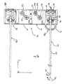
- the FIG. 1 shows an ultrasonic cleaning device 1, which comprises a trough 2, which can be filled with a liquid.
- a trough 2 On the underside 3 of the tub are sound transmission elements (not shown), which transmit ultrasound to the inner walls of the tub 2 and so transmit ultrasonic waves in the liquid contained in the tub 2.
- sound transmission elements not shown
- the illustrated ultrasonic cleaning device is a built-in device, which is embedded in the surface of a tray 4.
- the additional device 100 comprises a frame 110, which projects beyond the upper edge of the trough 2.
- an adapter bank 120 At the lower end of the frame 110 is an adapter bank 120, which is arranged such that it can be inserted into the trough 2.
- the control and / or operating unit 200 can via a cable connection with be connected to a drive of the additional device.
- the cable is both a motor of the drive supplied with electricity, as well as driven, so that performs these movements.
- the control of the control and operating unit 200 by a user is made via the touch-sensitive display 210. It may be a capacitive or resistive touch-sensitive screen.
- a control board 230 having processors and memory units disposed thereon.
- the frame 110 comprises two grip parts 111 and 112 extending in the xz-plane, by means of which the auxiliary device 100 can be put out of and into the trough.
- the handles 111 and 112 are rails 113 and 114, which connect the two handles together.
- an adapter bank 120 is additionally arranged, which in the present exemplary embodiment comprises four adapters 121 to 124.
- the frame 110 may be made of metal or a plastic. It is also possible that, for example, the handles 111 and 112 made of metal and the rails 113 and 114 are made of a plastic. On the rails 113, 114 are also elevations 115 and 116, so that the frame is only pointwise in contact with the tub. The constant width of the frame is ensured by cross struts 117.
- the adapter bank 120 comprises a housing 130 which at the same time forms the housing for the four adapters 121 to 124.
- the housing is made of plastic and includes openings 125 which allow liquid in the tub to enter the interior of the housing 130.
- the adapter 121 comprises at least one coupling element 140 or 142 which is movable relative to the housing.
- the coupling elements may be made of plastic, stainless steel, titanium, other medical materials or other chemically resistant or water-resistant materials and project over the surface 131 of the housing 130 in z Direction.
- the movable coupling elements 140 and 142 are resilient in the z-direction stored.
- the coupling elements sit on one in the representation of the FIG. 2 unrecognizable shaft, which is driven by a mechanical, hydraulic or pneumatic.
- the shaft is anchored to a bottom of the housing and has a spring mechanism which allows suspension of the coupling element in the z-direction. That is, the coupling element can be pressed in the negative z-direction at least by the height at which it projects beyond the surface 131.
- a drive 160 is also arranged, which is arranged at the upper end in the region of the handle 112. This comprises a housing 161, in which there is an electric motor in this case.
- the housing 161 is connected in the present example via a strut 118 to the adapter bank.
- FIG. 3a is a plan view of the adapter bank of FIG. 1 and 2 shown in the xy plane.
- a fixation device 150 as well as two medical instruments 170 and 170 'can be seen, so that the interaction between the instrument 170 and the coupling elements can be explained in more detail.
- the instrument 170 includes a shaft 172 which is rotatable along the axis of the shaft in the direction R.
- the shaft 172 also includes at its distal end a movable tip 173, which is rotatable in the yz plane in the direction B.
- the instrument comprises a housing (which is cut open in this plan view) which, inter alia, comprises four mechanisms 176, 178, 180 and 182.
- a rotation of the element 176 causes an opening in the direction 02
- the mechanism 180 causes a rotation in the direction O1
- the element 178 a rotation in the direction R
- the element 182 a rotation in the direction B.
- each includes the adapter of the adapter bank 120 has two movable coupling elements 144 and 146, which in each case comprises two grooves 148 extending in a crosswise manner relative to each other.
- the grooves are selected such that a pin located on the underside of the mechanisms 176 to 182, not shown, can be held in a form-fitting manner in the grooves.
- a movement of the coupling element 144 for example, into a movement of the mechanism 182 and thus an active movement of the tip 173 in the direction B is implemented.
- the mechanisms can each be rotated over a range of movement, ie a certain length, in order to pass from a first to a second stop.
- the first and second stops correspond to the extreme positions of the part of the instrument which is moved by the mechanism.
- the pins on the underside of the mechanism of the medical instrument first press against the region of the coupling element 144 or 146 which delimits the grooves.
- the coupling element is pressed in the z direction down.
- the pin of the mechanism now slips along the surface bounding the grooves 148 until it engages in one of the grooves.
- the pressure on the spring-mounted coupling element 144 is reduced and the coupling element is pressed in the positive z-direction upwards.
- the positive connection between the groove and the pin of the medical instrument is brought about.
- the movement of the distal part of the medical instrument may be such that the coupling element 144 is initially moved by certain clockwise and then by the same angle counterclockwise, thereby an active movement is transmitted to the medical instrument, so that the distal tip 173 can be bent over an angular range of for example 180 ° and the arms of the clamp over a range of also almost 180 ° can be moved.
- the grooves 148 serve inter alia also the fixation of the medical instrument.
- holes or webs can take over the function of the grooves.
- the shape of the fixing element, which is arranged on the coupling element, thus essentially depends on the mechanics of the medical instruments. If the medical instruments have pins, grooves or holes are preferable. Have these holes or grooves, webs or pins are used on the movable coupling element.
- each adapter has additional fixing aids.
- a recess 152 is present, which is embedded in the surface 131. In this area are in the illustrated medical instrument electrical contacts, which protrude slightly above the bottom of the medical instrument. These can be aligned in the recess 152, so that the positioning of the medical instrument in the adapter is simplified.
- a web 154 is present, which also engages in a corresponding recess in the underside of the medical instrument.
- the fixing device 150 also has as in the FIG. 3b recognizable, a latching lug 158 which engages in a corresponding recess of the medical instrument.
- the fixing device 150 comprises an undercut 160, which closes in a form-fitting manner with a projection 184 of the medical instrument.
- the fixed in the adapter 121 medical instrument 170 is fixed in its orientation relative to the adapter 121. Only the coupling via the coupling element 144 or 146 and the corresponding mechanism 178 and 182, respectively, causes active movement of the distal end of the medical instrument. Other parts or areas of the medical instrument are not moved by the coupling elements.
- the fixing device 150 also comprises a handle 156, which is pulled in the negative ⁇ -direction, the medical instrument 170 releases. This condition can be recognized, for example, in the adapter 124.
- the fixing element 150 comprises a stop, so that this can only be pulled over the half of the length of the adapter, for example, and then remains in the adapter. Also in this position, a release of the medical instrument from the adapter is possible.
- Both the adapter housing 130 and the coupling element 144, 146 and the gear train, not shown, which sits in the housing 130 may be made of plastic or metal.
- the fixing device 150 may also be made of plastic or metal.
- a flushing device 240 can be seen, which comprises hoses 242/244 for a suction flush and / or a pressure flush.
- the hoses or the flushing liquid located therein are sucked or pressed by means of a pump 246.
- the hoses 242 and 244 can, for example, with the in the FIG. 3a shown rinse adapter 190 (which is connected to the medical instrument 170), which connects the lumen of the shaft 172 with the hose.
- a program can be initiated via the touch-sensitive display, which allows a pressure or suction flushing of the lumen of the shaft 172.
- the controller 230 is programmed so that the single pump 246 can pressurize all four instruments located in the adapter bank 120 with a suction or pressure purge.
- the suction or pressure channel by channel that is, one adapter after another, carried out so that it can be determined at least for the suction irrigation, whether the lumen of the shaft of the medical instrument is clogged or not.
- the switching between suction and pressure operation is performed by a suction and pressure switch 248, the channel switching, ie the channel Actuation takes place in a channel switch, not shown.
- the blockage can be determined via the flow passing through the pump or the pressure associated therewith. Part of this technology is also used in the Sonomic products.
- the control device 230 includes, as mentioned above, a processor and a memory unit.
- the memory unit stores various programs for moving the instruments. Thus, depending on the inserted instrument, a program can be selected which defines the corresponding angular range of rotation of the instrument and the coupling elements to be controlled. These programs are initialized via the processor and the processor takes control of the drive so that it initiates the movement of the coupling elements according to the program.
- connection 250 is also a connection 250 recognizable, via which a connection between the drive 160 of the additional device 100 can take place with the control and / or control unit 200.
- a connection can be a copper connection.
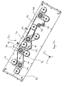
- Fig. 5a are shown in the housing 120 arranged components of the drive 160 in more detail.
- the perspective shown is looking from the bottom of the housing in the z direction.
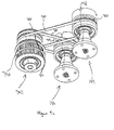
- a mechanism 300 which includes, inter alia, four shaft elements 301-304.
- the shaft element 301 is connected directly to the coupling rod 162, so that a movement of the motor arranged in the housing 161 is transmitted directly to the shaft element 301.
- the shaft element 301 is coupled to the shaft elements 302 and 303 by means of a first force transmission element 310 in the form of a toothed belt, so that a rotational movement of the shaft element 301 to the left causes a corresponding movement of the shaft elements 302 and 303.
- the toothed belt is guided a deflection element 305.
- the shaft member 301 is further coupled to the shaft member 304 via another first power transmission member 320. Also, this power transmission element 320 is guided over deflecting elements 306 and 307.
- the first power transmission elements 310 and 320 are formed in the present example as a toothed belt, which engage in corresponding teeth 330 of the shaft elements 301-304.
- the timing belt are under a mechanical tension, which further favors the transmission of motion of the shaft elements with each other.
- the first power transmission element may also be a belt without teeth.
- the power transmission element may provide for hydraulic or pneumatic motion transmission.
- the teeth of the shaft members may be similar to turbine blades, such that liquid or air moved by the shaft member 301 without a (closed) channel causes movement of the further shaft members 302-304.
- the shaft elements are cylindrical and are rotatably mounted on a shaft.
- the shaft 308 can be seen.
- a bearing for example, a sliding or ball bearings can be provided.
- Each shaft element 301-304 is coupled to two coupling elements each.
- the shaft element 302 is coupled to the coupling elements 144 and 146 via a respective second force transmission element 340 and 341 in the form of a respective round belt.
- provided with the grooves 148 surfaces of the coupling elements 144 and 148 protrude from openings of the housing 120 as in, for example, in Fig. 2 is shown.
- the shaft elements do not protrude out of the surface through their own openings.
- the round belt runs in a recess of the shaft member and the coupling element. This is for example in the FIG. 5c shown.
- the second power transmission element 340 runs in a groove 350 of the shaft element and a groove 360 of the coupling element.
- the second power transmission element 341 runs in a groove 351 of the shaft element and a groove 361 of the coupling element.
- a mechanic of a robotic medical instrument can engage in, for example, the groove 148 (or a corresponding groove of another coupling element). In this way, movement of the motor, via the coupling rod 162, the shaft elements 301-304 and the second force transmission elements transferred to the coupling elements and the distal ends of the example instruments 170 and 170 'are moved and the shaft of the instrument is rotated.
- a first and a second coupling elements are each coupled to a shaft element via a second force transmission element
- a first coupling element can move independently of the second coupling element in the sense that slippage of the round belt of the first coupling element has no influence on any movement of the first coupling element second coupling element has. In this way it is not important that the distal, movable ends of the instruments are in a predetermined position prior to insertion into an adapter.
- the motor is rotated in each case one direction of rotation for a distance corresponding to the full rotation circumference of the mechanics of the instrument, or the full maximum rotational range of the various mechanisms (each for moving a different Part of the instrument, such as the rotation of the shaft or the rotation of the distal end or various instruments inserted into various adapter of the adapter bank instruments), it can be ensured that all inserted into an adapter instruments are moved over their full range of motion, regardless of the starting position the mechanics of the instruments.
- the mechanics are temporarily moved simultaneously, ie not moved in succession, as long as the mechanism moved by the coupling element has not yet reached the stop.
- a rotational movement in the opposite direction over at least the previous route is performed. From this point on, a synchronization of the movements of the inserted instruments can be guaranteed.
- the duration of the first rotation and the subsequent second rotation, i. the first and second time periods are chosen to be longer than the time it takes for one of the moving mechanics at the given or set speed of the drive to travel through its respective full range of motion.
- the duration of the movement in the first or second direction can be reduced.
- the additional device is during cleaning in a liquid which can penetrate into the housing 120 and thus the movement resistance from which slippage is possible to raise or lower.
- a channel which causes a coupling of the shaft member with the coupling element comprise a pressure relief valve. Bring now a mechanics of an instrument one Resistance to movement on the coupling element, the pressure in the channel increases and the valve opens when a pressure is exceeded.
- the movement of the shaft member no longer leads to a movement of the coupling element, since the force applied to the coupling element resistance to movement is too high and exceeds a predetermined resistance to movement.
- the predetermined resistance to movement is chosen such that a mechanism of an instrument to be cleaned is not damaged.
- a shaft element comprises two rows of teeth for each one toothed belt or two grooves for each round belt. In other embodiments, the number may be varied in each case.
- the coupling element can have a functional division into two parts. It can thus be provided that an upper part of the coupling element that can be brought into engagement with the instrument is connected to a second part of the coupling element which is coupled to the second force transmission element such that when the upper part of the coupling element is acted upon by a movement resistance a movement decoupling of the upper and lower part of the coupling element takes place, in the sense that the two parts are still connected to each other (for example, via a bearing of the shaft), but can be rotated independently, as soon as the upper part undergoes a resistance movement.
- the upper and lower parts may, for example, each comprise mutually corresponding elevations and depressions (eg: wave pattern), which have a positive connection in the direction of power transmission, wherein the positive connection can be canceled by applying the predetermined resistance to movement and the two parts can be rotated against each other.
- the upper and the lower part should be adjustable in height relative to one another, for example along a bearing shaft.
- the upper and the lower part are thus connected to each other via a coupling, wherein the clutch comprises an idling, so that when subjected to the upper part with a resistance to movement the clutch goes into neutral and a movement of the upper part is decoupled from the lower part.
- the feature that the movement of the shaft member is not transmitted to the coupling member may also be expressed by providing a coupling between the second power transmission member and the coupling member which changes into an idling condition by applying the movement of the coupling member.
- a tub 400 is shown in which a non-drawn additional device for fixing medical instruments with four inserted instruments 401-404 is arranged.
- the accessory device may be the accessory device 100 described in this application.
- the position of the instruments 401-404 is predetermined by the auxiliary device.
- ultrasonic transducers 407-411 are located at the bottom of the tub 405 and on the tub wall 406 at the bottom of the tub 405 and on the tub wall 406. Since the selected plan view is on the tub from the outside into the tub interior, arranged on the outside of the tub bottom and the tub wall ultrasonic transducers are shown hatched, since they are actually not visible from the selected perspective. In this case, the ultrasonic transducers 407-410 are located at the bottom of the tub and the ultrasonic transducers 411 are located at the tub wall.
- the ultrasound transducer 407 is located just below the distal tip or in the immediate vicinity of the distal tip of the instrument 401.
- the ultrasonic transducers 408 and 409 are disposed below the shaft of the instrument.
- the ultrasonic transducer 410 is located below the adapter 412 of the instrument.
- the adapter is further sonicated by the arranged on the tub wall ultrasonic transducer 411, which is located at the height of the instrument, preferably at the level of the flushing connections of the instrument.
- Below or on the side of the other instruments 402-404 are further ultrasonic transducers 413, which analog are arranged to the ultrasonic transducers 407-411.
- the distance between the ultrasonic transducers 407-410 with each other can be uniform.
- the tub 400 is shown with an alternative attachment (not shown) for holding MIC instruments 421-424.
- the arrangement of the ultrasonic transducers is also such that at least one ultrasonic transducer 427 is arranged in the region of the distal tip of the instrument.
Landscapes
- Health & Medical Sciences (AREA)
- Surgery (AREA)
- Life Sciences & Earth Sciences (AREA)
- Heart & Thoracic Surgery (AREA)
- Pathology (AREA)
- Oral & Maxillofacial Surgery (AREA)
- Engineering & Computer Science (AREA)
- Biomedical Technology (AREA)
- Nuclear Medicine, Radiotherapy & Molecular Imaging (AREA)
- Medical Informatics (AREA)
- Molecular Biology (AREA)
- Animal Behavior & Ethology (AREA)
- General Health & Medical Sciences (AREA)
- Public Health (AREA)
- Veterinary Medicine (AREA)
- Surgical Instruments (AREA)
Abstract
Description
- Die Erfindung betrifft eine Zusatzvorrichtung für ein Ultraschallgerät bzw. ein Ultraschall-Reinigungsgerät, eine Steuer- und/oder Bedienvorrichtung für ein Ultraschallgerät mit einer derartigen Zusatzvorrichtung, sowie ein Verfahren zur aktiven Bewegung zumindest eines Bereichs eines medizinischen Instruments in einem Ultraschall-Reinigungsgerät.
- Bei der Reinigung von medizinischen Instrumenten durch niederfrequenten Ultraschall werden Fremdpartikel auf oder in medizinischen Instrumenten aufgrund spezifischer Ultraschallwirkmechanismen (wie Kavitation, Microstreaming, Jetbuilding, etc.) gelöst.
- Hierbei werden insbesondere chirurgische Instrumente in einen Korb gelegt und anschließend in einer mit einer Flüssigkeit befüllten Wanne eines Ultraschall-Reinigungsgeräts eingebracht. Anschließend wird die Wanne mit Ultraschall beaufschlagt, so dass sich Fremdpartikel und Anhaftungen in kurzer Zeit lösen können. Optional wird dieser Prozess durch den Zusatz geeigneter Reinigungs- und/oder Desinfektionspräparate die der Flüssigkeit zugegeben werden unterstützt.
- Eine weitere Anwendung ist aus dem Bereich der Laparoskopie bekannt. Hierbei können Fremdpartikel nicht nur an der Außenseite des Instruments, sondern auch in einem Lumen des Schaftes auftreten. Um hier eine reinigende Wirkung zu entfalten, sind Vorrichtungen wie beispielsweise das Produkt Sonomic der BANDELIN electronic GmbH & Co, KG bekannt. Bei diesem Produkt wird an das distale Ende des Schaftes ein Adapter angebracht, welcher es ermöglicht, Flüssigkeit vom proximalen zum distalen Ende des Schaftes zu ziehen, so dass sich die Wirkung des Ultraschalls auch im Inneren des Schaftlumens entfalten kann.
- Prinzipiell kann eine derartige Reinigungstechnik auch bei Instrumenten aus dem Bereich der robotergestützten minimal invasiven Chirurgie, wie zum Beispiel die EndoWrist®-Produkte des daVinci-Systems von Intuitive Surgical Inc., angewandt werden, Diese Instrumente weisen zumeist mehr als eine Mechanik auf, wobei eine Mechanik jeweils eine bestimmte Bewegung des Instruments bewirkt, z.B. eine Rotation des Instrumentenschafts, oder eine Bewegung eines Greifers am distalen Ende des Instrumentenschafts.
- Jedoch besteht hier weiterer Bedarf, die Reinigungswirkung für medizinische Instrumente zu verbessern. Hierzu wurde taggleich eine europäische Patentanmeldung der gleichen Anmelderin eingereicht. Aufgabe der vorliegenden Anmeldung ist einen Antrieb für eine Zusatzvorrichtung zur Verfügung zu stellen.
- Die Aufgabe wird gelöst gemäß einem Antrieb nach den Merkmalen des Anspruchs 1 sowie einer Zusatzvorrichtung für Ultraschall-Reinigungsgeräte nach den Merkmalen des Anspruchs 14.
- Ein Antrieb umfasst zumindest ein Wellenelement, welches über ein erstes Kraftübertragungselement antreibbar ist, wobei das Wellenelement mit mindestens einem Koppelelement über ein zweites Kraftübertragungselement gekoppelt ist, so dass eine Bewegung vom Wellenelement auf das mindestens eine Koppelelement übertragbar ist. Das zweite Kraftübertragungselement ist derart mit dem mindestens einen Koppelelement gekoppelt ist, dass beim Überschreiten eines vorbestimmten Bewegungswiderstands des mindestens einen Koppelelements das zweite Kraftübertragungselement keine Bewegung des Wellenelements auf das mindestens eine Koppelelement überträgt.
- Mit Hilfe des vorbeschriebenen Antriebs ist es möglich eine aktive Bewegung von medizinischen Robotikinstrumenten in einem Ultraschallbad zu gewährleisten ohne eine Mechanik zum Bewegen einzelner Teile des Instruments zu beschädigen.
- Im Ultraschallbad wird das Instrument derart bewegt bzw. rotiert, dass ein Teilelement des Koppelelements mit der Mechanik des Instruments im Eingriff steht und so eine Bewegung des Koppelelements auf das Instrument übertragen wird. Sobald die Mechanik des Geräts an einem Anschlag angelangt ist, bringt die Mechanik des Instruments einen Bewegungswiderstand auf, welcher nur durch Aufbringen einer sehr hohen Kraft überwunden werden kann. Allerdings würde diese sehr hohe Kraft zu einer Beschädigung der Mechanik des Instruments führen. Der aufgebrachte Bewegungswiderstand der Mechanik des medizinischen Instruments führt zu einem Bewegungswiderstand des Koppelelements, d.h. das Koppelelement durch die Mechanik des Instruments an einer weiteren Drehbewegung gehindert. Der Widerstand zwischen dem zweiten Kraftübertragungselement und dem Koppelelement ist derart gewählt das dieser geringer ist als der von der Mechanik des Instruments bewirkte Bewegungswiderstand. Erreicht eine Mechanik des Instruments also den Anschlag, wird das entsprechende Koppelelement mit einem Bewegungswiderstand beaufschlagt und eine Bewegung des Wellenelements wird nicht mehr auf das Koppelelement übertragen. So kann das Instrument bzw. Teil davon aktiv bewegt werden, die Mechanik des Instruments wird geschützt und das Instrument kann gut gereinigt werden ohne dessen Funktionalität einzuschränken.
- In einem weiteren Ausführungsbeispiel sind ein erstes und ein zweites Koppelelemente über jeweils ein zweites Kraftübertragungselement mit einem Wellenelement gekoppelt, so dass sich ein erstes Koppelelement unabhängig vom zweiten Koppelelement bewegen kann. Auf diese Weise ist es nicht wichtig, dass sich die distalen, beweglichen Enden der Instrumente vor dem Einlegen in einen Adapter in einer vorbestimmten Position befinden, da die Bewegungen der Koppelelemente voneinander entkoppelt sind. Für den Fall, das der Antrieb derart ausgebildet ist, dass mehr als ein Koppelelement zur Kopplung an jeweils eine Mechanik des Instruments vorhanden ist, können die Koppelelemente mit einem, vorzugsweise einzigem, Antrieb derart angetrieben werden, dass ein erstes Koppelelement, welches eine erste Mechanik des Instruments an den Anschlag bewegt hat, nicht länger eine Bewegung auf die erste Mechanik überträgt und ein zweites Koppelelements, welches eine zweite Mechanik des Instruments bewegt, diese zweite Mechanik weiterhin in Bewegung hält. In anderen Worten können das erste und ein zweites (oder auch weitere) Koppelelement unabhängig voneinander, jedoch gleichzeitig, eine Bewegung auf eine erste bzw. zweite Mechanik des Instruments übertragen, wobei die mit den Koppelelementen gekoppelten Kraftübertragungselemente gleichzeitig von einem einzigen Antrieb angetrieben werden. Zwischen den Kraftübertragungselementen und den Koppelelementen kann beispielsweise jeweils eine Rutschkupplung angeordnet sein. Gleichzeitig ist hier derart zu verstehen, dass sowohl das erste als auch das zweite Koppelelement zeitgleich jeweils eine mit dem ersten bzw. zweiten Koppelelement gekoppelte erste bzw. zweite Mechanik des Instruments bewegen können. Gelangt eine der ersten oder zweiten Mechanik an einen Anschlag greift eine Rutschkupplung und es wird anschließend nur noch die noch nicht am Anschlag angelangte Mechanik bewegt. Vorzugsweise ist der Antrieb derart konfiguriert, dass mehr als eine Mechanik eines Instruments, und mehr als ein Instrument bewegbar sind, d.h. ein einziger Antrieb zwei oder mehr Instrumente bewegt, wobei die eine oder mehr als eine Mechanik der zwei oder mehr Instrumente gleichzeitig bewegt werden können. Zudem erfolgt die Bewegung der Mechaniken unabhängig voneinander, d.h. während eine am Anschlag angelangte Mechanik nicht weiter bewegt wird, können die weiteren durch den Antrieb und noch nicht an ihrem Anschlag angelangten Mechaniken weiterhin bewegt werden.
- Als Kraftübertragungselemente kommen in weiteren Ausführungsformen Riemen, beispielsweise Zahnriemen oder Rundriemen aus Kunststoff, Plastiken oder Gummi zu Einsatz. Weitere Ausführungsformen finden sich in den Ansprüchen.
- Mit dem hier beschriebenen Antrieb ist es möglich ein Verfahren zur Steuerung des Antriebs zu implementieren, bei welchem der Antrieb zunächst eine erste Zeitperiode in einer ersten Richtung, und anschließend für eine zweite Zeitperiode in einer zweiten, der ersten Richtung entgegengesetzten Richtung angetrieben wird. Die Länge der Zeitperiode wird unter anderem in Abhängigkeit von der Geschwindigkeit gewählt mit welcher der Antrieb die Koppelelemente antreibt. Da eine Mechanik des Instruments einen maximalen Bewegungsbereich hat, werden die erste und zweite Zeitperiode derart gewählt, dass diese länger ist als die Zeit, in welcher eine durch ein Koppelement angetriebene Mechanik den maximalen Bewegungsbereich durchläuft. Auf diese Weise wird innerhalb eines Zeitraums der ersten und zweiten Zeitperiode erreicht, dass alle durch ein Koppelelement angetriebenen Mechaniken an einem Anschlag angelangt sind. Für den Fall das alle mit jeweils einem Koppelelement gekoppelten Teile einer Mechanik einen identischen Bewegungsbereich (im Sinne einer Distanz), d.h. Bewegungslänge besitzen, kann nach der ersten und zweiten Zeitperiode eine kürzere Zeitperiode eingestellt werden, wobei die kürzere Zeitperiode der Länge entspricht, welche die Teile der Mechaniken benötigen, um den jeweiligen, vollen Bewegungsbereich zu durchlaufen. Für den Fall, dass unterschiedliche Mechaniken unterschiedliche Bewegungsbereiche besitzen, d.h. die durch den Teil der Mechanik zurücklegbare Strecke der Teil sich von einander unterscheiden kann, ist es nach dem durchlaufen der ersten und zweiten Zeitperiode möglich eine kürzere Zeitperiode zu wählen, welche diejenige Mechanik mit der größten zurückzulegenden Strecke für einen vollen Bewegungsbereich benötigt. Hierdurch ist es möglich, dass während der Reinigung der Instrumente in einem Reinigungsbad, insbesondere einem mit Ultraschall beaufschlagten Reinigungsbad, sämtliche Teile der Mechanik über ihren vollen Bewegungsbereich bewegt werden, so dass die Reinigungswirkung der mit dem Ultraschall beaufschlagbaren Flüssigkeit in sämtlichen Bewegungszuständen der durch den Antrieb bewegten Teil der Mechanik wirken kann und so die Reinigungswirkung maximiert wird.
- Die erste und zweite Zeitperiode können gleich oder unterschiedlich lang gewählt sein. Da ein an seinem Anschlag angelangter Teil der Mechanik nicht länger durch das Koppelelement bewegt wird (da das Kraftübertragungselement beispielweise durchrutscht bzw. eine Rutschkupplung eine Bewegung des Antriebs auf das Koppelelement entkoppelt), können weitere, durch ein weiteres Koppelelement angetriebenen Teile der Mechanik bis an jeweils ihren Anschlag bewegt werden und dies unabhängig davon, ob andere Teile der Mechanik bereits an ihrem Anschlag angelangt sind. Nach der ersten und zweiten Zeitperiode kann die Länge der folgenden Zeitperioden zur Bewegung des Antriebs in der ersten oder zweiten Richtung reduziert werden, so dass ein Reinigungsdurchlauf insgesamt verkürzt wird ohne die Reinigungswirkung zu reduzieren. Aufwendige Sensorik zur Feststellung, ob eine der bewegten Mechaniken sich bereits am Anschlag befindet, ist nicht notwendig und in einigen Ausführungsbeispielen nicht vorgesehen.
- Nachfolgend werden Aspekte der Zusatzvorrichtung beschrieben, welche frei mit den Merkmalen der Ansprüche kombinierbar sind.
- Die Zusatzvorrichtung umfasst vorzugsweise ein Gestell und zumindest einen Adapter für ein medizinisches Instrument. Die Zusatzvorrichtung ist derart ausgebildet, dass diese in einer Wanne eines Ultraschallgeräts, vorzugsweise eines Ultraschall-Reinigungsgeräts Platz findet. Dabei ist es vorteilhaft, wenn Teile des Gestells aus der Wanne herausragen, um so eine vereinfachte Handhabung der Zusatzvorrichtung beim Einbringen und Ausbringen aus der Wanne zu gewährleisten.
- Der Adapter für das medizinische Instrument umfasst ein Gehäuse und mindestens ein gegenüber dem Gehäuse bewegbares und mit dem medizinischen Instrument koppelbares Kopplungselement. Dieses Kopplungselement ist mittels eines Antriebs bewegbar. Eine Bewegung des Kopplungselements bewirkt bei eingelegtem medizinischem Instrument eine aktive Bewegung zumindest eines Bereichs des medizinischen Instruments.
- Instrumente aus dem Bereich der Telemedizin (und weitere Instrumente) besitzen Mechaniken, durch welche es möglich ist, bestimmte Bewegungen des medizinischen Instruments durchzuführen. So kann beispielsweise bei einem endoskopartigen Instrument der Schaft und die Spitze zumindest in einer die Rotationsachse des Schaftes umfassenden Ebene rotiert werden. Weiterhin ist es möglich, dass das Instrument selbst Greifarme oder ähnliches besitzt, welche in einer weiteren Ebene, senkrecht zur vorgenannten Ebene rotierbar ist. Das in dem Adapter angeordnete Kopplungselement ist derart ausgebildet, dass es an eine Mechanik des medizinischen Instruments andocken kann und somit eine Bewegung des Kopplungselements in eine aktive Bewegung zumindest eines Bereichs des medizinischen Instruments umgesetzt wird. Das heißt, das Kopplungselement ist derart ausgebildet, dass eine Bewegung des Kopplungselements, wie beispielsweise eine Rotation des Schaftes des medizinischen Instruments, oder eine Bewegung der distalen Spitze des medizinischen Instrumentes bewirkt wird.
- Damit das Kopplungselement zuverlässig an das medizinische Instrument gekoppelt werden kann, so dass eine Bewegung das Kopplungselement in eine aktive Bewegung eines Bereichs des medizinischen Instrumentes umgesetzt wird, kann der Adapter Ausnehmungen, Stege oder ähnliches umfassen, welche zu Stegen bzw. Ausnehmungen eines medizinischen Instruments korrespondieren. Auf diese Weise kann sichergestellt werden, dass das Kopplungselement an vordefinierten Punkten des medizinischen Instruments angreift, vorzugweise an Mechaniken des medizinischen Instruments ansetzt, welche für eine aktive Bewegung zumindest eines Bereichs des medizinischen Instruments notwendig sind.
- Aufgrund der aktiven Bewegung des medizinischen Instruments durch die Zusatzvorrichtung, kann das medizinische Instrument während der Beaufschlagung der Wanne mit Ultraschall aktiv bewegt werden, so dass eine verbesserte Reinigungswirkung im Bereich der sich bewegenden Teile des medizinischen Instruments gewährleistet wird. Auf diese Weise wird gewährleistet, dass der Ultraschall auch bei eng aneinander anliegenden mechanischen bzw. beweglichen Teilen des Instruments seine volle Wirkung entfalten kann und Fremdpartikel zuverlässig von dem medizinischen Instrument, auch von verdeckten Teilflächen in z.B. Gelenken, entfernt werden.
- In einer Ausführungsform der Zusatzvorrichtung umfasst der Adapter eine Fixierungsvorrichtung zum Fixieren des medizinischen Instruments. Zusätzlich oder optional zu dem bereits erwähnten Ausnehmungen oder Stegen des Adapters, kann eine Fixierungs- oder Verriegelungsvorrichtung vorgesehen sein, welche zumindest einen weiteren Bereich des medizinischen Instruments auf dem Adapter fixiert. Dabei ist die Fixierung dergestalt, dass das Kopplungselement der Zusatzvorrichtung an einem Punkt des medizinischen Instruments angreift, welcher eine aktive Bewegung eines Bereichs des medizinischen Instruments, welcher nicht durch die Fixierungsvorrichtung fixiert ist, bewirkt. Im Falle eines chirurgischen Robotikinstruments kann dies beispielsweise bedeuten, dass das proximale Ende des Instruments, welches zu Zwecken eines medizinischen Eingriffs mit einem Roboterantrieb verbunden wird, in den Adapter eingesetzt wird und durch die Fixiervorrichtung verriegelt wird. Zwar ist nunmehr das proximale Ende des medizinischen Instruments fixiert, jedoch ist das Kopplungselement des Adapters derart an das proximale Ende des medizinischen Instruments gekoppelt, dass sowohl der Schaft als auch die Instrumente am distalen Ende des medizinischen Instruments durch eine Bewegung des Kopplungselements aktiv bewegt werden.
- In einer weiteren Ausführungsform umfasst die Zusatzvorrichtung an einer dem medizinischen Instrument zugewandten Oberfläche des Kopplungselements eine Nut oder einen Steg, welche(r) in einen mechanischen Formschluss mit einer Mechanik des zu reinigenden medizinischen Instruments gebracht werden kann. Ist die Mechanik des medizinischen Instruments beispielsweise durch einen Stift bzw. eine Nut gegeben, so ist die Nut bzw. der Steg des Kopplungselements dazu korrespondierend ausgebildet. Auf diese Weise kann eine Bewegung des Kopplungselements direkt auf die Mechanik des medizinischen Instruments übertragen werden.
- In einer weiteren Ausführungsform ist das Kopplungselement federnd gelagert. Da das Kopplungselement bevorzugt derart ausgebildet ist, in eine Mechanik des medizinischen Instruments einzugreifen, die Mechanik des medizinischen Instruments und das Kopplungselement jedoch nicht in jeder Orientierung zueinander ineinandergreifen können, kann das Kopplungselement federnd gelagert sein. Dies bewirkt, dass beim Einlegen des medizinischen Instruments das Kopplungselement zunächst nach unten gedrückt wird, sofern es nicht mit der Mechanik des medizinischen Instruments in Eingriff steht, das heißt, dass eine Bewegung des Kopplungselements in eine aktive Bewegung eines Bereichs des medizinischen Instruments umgewandelt werden kann. Durch die federnde Lagerung kann zunächst das Kopplungselement bewegt werden, so dass es eine Position einnimmt, in welcher das Kopplungselement mit der Mechanik des medizinischen Instruments in Eingriff tritt. Dies kann beispielsweise dadurch passieren, dass ein Stift der Mechanik in eine Nut des Adapters eingreift. Erst durch den Eingriff überträgt sich eine Bewegung des Kopplungselements auf die Mechanik und wird so in eine aktive Bewegung des medizinischen Instruments umgewandelt. Durch das Einrutschen des Stiftes in die Nut drückt eine Federwirkung (oder eine vergleichbare Wirkung) das Kopplungselement in Richtung des medizinischen Instruments und bewirkt so einen Formschluss zwischen einer Mechanik des medizinischen Instruments und dem Kopplungselement.
- In einer weiteren Ausführungsform ist das Kopplungselement derart durch einen Antrieb bewegbar, dass dieses rotiert wird. Dabei kann der Antrieb derart ausgebildet sein, dass das Kopplungselement abwechselnd in eine und anschießend in eine entgegengesetzte Richtung rotiert wird. Es sind jedoch auch Varianten mit einer linearen Bewegung des Kopplungselements bei entsprechenden medizinischen Instrumenten möglich.
- In einer weiteren Ausführungsform der Erfindung ist die Zusatzvorrichtung bzw. das Kopplungselement mechanisch, hydraulisch oder pneumatisch mit einem Antrieb gekoppelt. Hierdurch kann erreicht werden, dass keinerlei elektrische Komponenten des Antriebs sich innerhalb der Wanne des Ultraschallgeräts befinden müssen. Dies vereinfacht die betriebliche Sicherheit und die Zuverlässigkeit der Zusatzvorrichtung. Das Kopplungselement kann demnach mechanische, hydraulische oder pneumatische Getriebe aufweisen, welche eine Verbindung an beispielsweise einen Elektromotor ermöglichen.
- In einer weiteren Ausführungsform ist das Gestell derart ausgebildet, dass eine am Gestell angeordnete krafterzeugende Komponente des Antriebs, wie beispielsweise ein Elektromotor außerhalb der Wanne und der mindestens eine Adapter von der krafterzeugenden Komponente beabstandet innerhalb der Wanne angeordnet ist. Hierdurch sind keinerlei elektrische Komponenten der Wirkung des Ultraschalls ausgesetzt, obgleich die medizinischen Instrumente vollständig in der Wanne versenkbar sind. Dies erhöht die Langlebigkeit der Zusatzvorrichtung. Weiterhin kann, beispielsweise im Falle eines Elektromotors, auf weiterführende Sicherheitsmaßnahmen verzichtet werden, da keinerlei elektrische Komponenten in die Wanne bzw. in die mit dem Ultraschall beaufschlagte Flüssigkeit eingebracht wird.
- In einer weiteren Ausführungsform ist das Gehäuse des Adapters der Zusatzvorrichtung gegenüber dem Gestell fixiert. Der Adapter ist gegenüber dem Gestell unbeweglich, so dass sich lediglich das Kopplungselement gegenüber dem Gestell bewegen kann. Auf diese Weise ist es möglich, einen Teil des medizinischen Instruments zu fixieren und über das Kopplungselement einen weiteren Bereich des medizinischen Instruments aktiv zu bewegen.
- In einer weiteren Ausführungsform umfasst die Zusatzvorrichtung Öffnungen in dem Gehäuse des Adapters, so dass die Flüssigkeit, welche sich in der Wanne befindet, über den Adapter bis in das medizinische Instrument eindringen kann. Hierdurch wird die reinigende Wirkung auf sämtliche Bereiche des medizinischen Instruments verbessert.
- In einer weiteren Ausführungsform ist die Zusatzvorrichtung mit einer Saug- und/oder Druckspülungsvorrichtung zur Spülung des medizinischen Instruments verbunden, wobei die Spülungsvorrichtung einen Spüladapter zur Kopplung an das medizinische Instrument umfasst. Zahlreiche Instrumente weisen in einem Schaft ein oder mehrere Lumen auf. Je nachdem, welcher Bereich des medizinischen Instruments in dem Adapter fixiert wird, kann es opportun sein, eine Druckspülung oder eine Saugspülung durch den Schaft vorzunehmen. Hierzu wird eine Saug- und/oder Druckspülungsvorrichtung mittels eines Spüladapters an das medizinische Instrument gekoppelt. In weiteren Ausführungsformen kann alternierend sowohl Flüssigkeit durch den Spüladapter gesogen oder durch diesen in das Instrument gedrückt werden. In weiteren Ausführungsformen ist es möglich, mehr als einen Spüladapter mit dem medizinischen Instrument zu koppeln, um so gleichzeitig in einigen Bereichen eine Saugspülung und in anderen Bereichen des Instruments eine Druckspülung durchzuführen.
- Mithilfe der Saug- und/oder Druckspülungsvorrichtung ist es möglich, während der aktiven Bewegung des medizinischen Instruments auch die Lumen des medizinischen Instruments zu spülen, um so die Wirkung des Ultraschalls auch im Inneren der medizinischen Instrumente zu verbessern. Hierbei ist eine Steuerung vorgesehen, welche die aktive Bewegung des medizinischen Instruments, das heißt die Bewegung des Kopplungselements und die Saug- und/oder Druckspülungsvorrichtung steuert.
- Ein weiterer Aspekt der Erfindung betrifft eine Steuer- und/oder Bedienvorrichtung für ein Ultraschallgerät, welches zur Steuerung der Zusatzvorrichtung konfiguriert ist. Die Steuerung der Steuer- und/oder Bedienvorrichtung kann dabei eine Steuerungseinheit und eine Speichereinheit umfassen. Die Steuerungseinheit kann beispielsweise programmierbare Field-Arrays, Mikroprozessoren, Mikrocontroller oder ähnliche Vorrichtungen umfassen, welche dazu ausgebildet sind Instruktionen, beispielsweise eines Programmcodes, umzusetzen und hierdurch die Steuerung von Motoren, Pumpen oder ähnlichem zu bewirken. Die Steuer- und/oder Bedienvorrichtung ist dabei derart ausgebildet, dass eine regelmäßige periodische Bewegung des mindestens einen Kopplungselements durch den Antrieb ermöglicht wird. Dies kann beispielsweise bedeuten, dass das Kopplungselement für einen vorbestimmten Zeitraum nach links gedreht oder nach vorne bewegt wird, und für einen weiteren vorbestimmten Zeitraum in die entgegengesetzte Richtung bewegt wird, Die hierzu notwendigen Instruktionen können beispielsweise als Software in der Speichereinheit der Steuer- und/oder Bedienvorrichtung abgelegt werden. Bei der Speichereinheit kann es sich um volatilen oder nicht-volatilen Speicher handeln. Bevorzugt kommt ein Flash-Speicher zur Anwendung.
- Weitere Programme zur Bewegung des Kopplungselements können ebenfalls als Software abgelegt werden. Hierdurch kann die jeweils gewünschte Bewegung des Koppelelements bewirkt werden. Die Steuer- und/oder Bedieneinheit kann den Antrieb umfassen oder kann mittels einer Daten- und/oder Stromverbindung mit einem externen, an der Zusatzvorrichtung angeordneten Antrieb verbunden sein. Hierzu ist einer Ausführungsform vorgesehen, dass ein Antrieb der Zusatzvorrichtung mittels eines Kabels und einer Steckverbindung zum einen durch die Steuer- und/oder Bedienvorrichtung mit Strom versorgt wird und zum anderen der Antrieb durch die Steuervorrichtung angesteuert wird.
- In einer weiteren Ausführungsform umfasst die Steuer- und/oder Bedienvorrichtung die Spülungsvorrichtung, welche über einen Spüladapter mit dem medizinischen Instrument verbunden werden kann. Dabei ist die Steuer- und/oder Bedienvorrichtung derart konfiguriert, dass diese nicht nur den Bewegungsablauf des Kopplungselements regelt, sondern optional hierzu auch die Spülvorgänge eines Lumens des medizinischen Instrumentes steuert. So kann beispielsweise bei einer Bewegung des Kopplungselements in einer ersten Richtung eine Saugspülung des Instruments und bei dem Bewegen des Kopplungselements in einer zweiten, der ersten entgegengesetzten Richtung eine Druckspülung veranlasst werden. Alternativ kann über eine gleichzeitig aufgebrachte Druck- und -Saugspüfung, welche jeweils über verschiedene Adapter umgesetzt wird, ein Flüssigkeitskreislauf innerhalb der Lumen des medizinischen Instruments erwirkt werden. Der Steuer- und/oder Bedienvorrichtung kommt hierbei die Aufgabe zu, die Spülvorgänge und die aktive Bewegung des medizinischen Instruments aufeinander abzustimmen und somit den größtmöglichen Reinigungseffekt zu erzielen.
- In einer weiteren Ausführungsform umfasst die Steuer- und/oder Bedienvorrichtung ein berührungsempfindliches Display. Auf dem berührungsempfindlichen Display können verschiedene Piktogramme für das Abrufen der unterschiedlichen Funktionen der Steuer- und/oder Bedienvorrichtung abgebildet werden. So ist es beispielweise möglich, nur die Spülvorrichtung, nur die aktive Bewegung oder beide Programme gleichzeitig zu starten. Auch die Kontrolle der Ultraschallerzeuger zum Beaufschlagen der Wanne mit Ultraschall wird durch die Steuer- und/oder Bedienvorrichtung durchgeführt. Somit kann die Steuer- und/oder Bedienvorrichtung für verschiedene Ultraschall-Reinigungsgeräte und deren Zubehör eingesetzt werden. Zudem können weitere Funktionalitäten und/oder Ergänzungen der Funktionalitäten durch eine Schnittstelle in die Steuervorrichtung eingespielt werden, so dass Aktualisierungen der Software und einer Erweiterung der Steuerung möglich ist.
- Eine Wanne mit Ultraschallwandler zur Beaufschlagung von Instrumenten mit Ultraschall, beispielsweise in einer hier geschilderten Zusatzvorrichtung ist für sich alleine und in Kombination mit der hier beschriebenen Zusatzvorrichtung ein beanspruchbarer Anmeldegegenstand.
- Die Ultraschallwandler sind dabei derart an der Wanne angeordnet, dass die an einem Wannenboden angeordneten Ultraschallwandler dem Verlauf eines zu reinigenden Instruments folgend aufgebracht sind. Die Ultraschallwandler können dabei Piezoschallgeber oder andere im Stand der Technik bekannte Ultraschallerzeuger sein. Die Schallwandler werden an der Außenseite der Wanne angeordnet und derart ausgerichtet, dass der Schall im Wesentlichen von der Wanne in das Wanneninnere abgegeben wird.
- Hinsichtlich der Anordnung der Ultraschallwandler sind diese im Falle eines sich gerade erstreckenden Instruments derart am Wannenboden platziert, dass mindestens zwei oder mehr Ultraschallwandler genau unterhalb des Robotikinstruments liegen. Für den Fall, dass die Zusatzvorrichtung mehr als ein Instrument fixiert, werden die Ultraschallwandler beispielsweise entlang mehrerer Reihen angeordnet, wobei eine Reihe jeweils genau unterhalb einem eingelegten Instrument angeordnet ist. Es kann vorgesehen sein an der Zusatzvorrichtung Abstandsvorrichtungen anzubringen, um die Zusatzvorrichtung gegenüber der Wanne genau auszurichten bzw, zu positionieren. Für den Fall, dass die zu reinigenden Instrumente gekrümmt sind, werden die Ultraschallwandler am Wannenboden ebenfalls dem Verlauf des Instruments folgend angeordnet. D.h. die geometrische Anordnung der Ultraschallwandler orientiert sich an der Geometrie des zu reinigenden Instruments. Bevorzugt wird zumindest ein Ultraschallwandler derart platziert, dass dieser genau unterhalb einer zu reinigenden distalen Einheit eines Robotikinstruments angeordnet ist. Auf diese Weise wird die Reinigung der Instrumente gegenüber herkömmlichen Ultraschallwandleranordnungen verbessert.
- In einer Ausführungsform umfasst die Wanne auch mindestens einen Ultraschallwandler an einer Wannenwand. Dieser ist beispielsweise derart angeordnet, dass dieser im Bereich etwaiger Spülanschlüsse eines zu reinigenden Instruments angeordnet ist. Außer Robotikinstrumenten können auch andere chirurgische Instrumente, wie z.B. instrumente für die MIC (Minimal-Invasive Chirurgie) in die Wanne eingesetzt werden.
- Weitere Ausführungsbeispiele werden anhand der nachfolgenden Figuren erläutert.
- Es zeigen:
- FIG. 1
- eine Aufsicht eines Ultraschall-Reinigungsgerätes mit einer Zusatzvorrichtung;
- FIG. 2
- Detailansicht der Zusatzvorrichtung der
FIG. 1 ; - FIG. 3a
- weitere Detailansicht der Zusatzvorrichtung der
FIG. 1 ; - FIG. 3b
- Beispiel einer Fixiervorrichtung eines Adapters; und
- FIG. 4
- Steuerungseinheit und Spülvorrichtung einer geöffneten Steuer- und/oder Bedieneinheit;
- Fig. 5a
- eine Variante eines Antriebs für eine Zusatzvorrichtung;
- Fig. 5b
- der Antrieb der
Fig. 5a aus einer geänderten Perspektive; - Fig. 5c
- Detailansicht von Komponenten der
Fig. 5a ; - Fig. 6a, b
- Beispiele einer Anordnung von Schallwandlern zur Beaufschlagung von Instrumenten mit Ultraschall.
- Die
FIG. 1 zeigt ein Ultraschall-Reinigungsgerät 1, welches eine Wanne 2 umfasst, die mit einer Flüssigkeit befüllt werden kann. Auf der Unterseite 3 der Wanne befinden sich Schallübertragungselemente (nicht dargestellt), welche Ultraschall auf die Innenwände der Wanne 2 übertragen und so Ultraschallwellen in die in der Wanne 2 befindliche Flüssigkeit übertragen. Bei dem dargestellten Ultraschall-Reinigungsgerät handelt es sich um ein Einbaugerät, welches in die Oberfläche einer Ablage 4 eingelassen ist. - In der Wanne 2 befindet sich eine Zusatzvorrichtung 100, welche in den nachfolgenden Figuren näher erläutert wird. Die Zusatzvorrichtung 100 umfasst ein Gestell 110, welches über die Oberkante der Wanne 2 hinausragt. Am unteren Ende des Gestells 110 befindet sich eine Adapterbank 120, welche derart angeordnet ist, dass diese in die Wanne 2 eingelassen werden kann. Ist die Wanne 2 nun mit Flüssigkeit befüllt, bedeckt die Flüssigkeit die Adapterbank 120 und etwaige darauf angeordnete medizinische instrumente vollständig.
- Die Steuer- und/oder Bedieneinheit 200 kann über eine Kabelverbindung mit einem Antrieb der Zusatzvorrichtung verbunden werden. Über das Kabel wird sowohl ein Motor des Antriebs mit Strom versorgt, als auch angesteuert, so dass dieser Bewegungen ausführt. Die Steuerung der Steuer- und Bedieneinheit 200 durch einen Benutzer wird über das berührungsempfindliche Display 210 vorgenommen. Es kann sich dabei um einen kapazitiven oder resistiven berührungsempfindlichen Bildschirm handeln. Weiterhin ist in der Darstellung der
FIG. 1 eine Pumpe 246 zu erkennen. Weiterhin ist eine Steuerungsplatine 230 mit darauf angeordneten Prozessoren und Speichereinheiten dargestellt. - In der
FIG. 2 ist die Zusatzvorrichtung 100 ohne die sie in derFIG. 1 umgebenden Wanne 2 dargestellt. Das Gestell 110 umfasst zwei in der x-z-Ebene verlaufende Griffteile 111 und 112, mittels derer die Zusatzvorrichtung 100 aus und in die Wanne gestellt werden kann. Am unteren Ende der Griffe 111 und 112 befinden sich Schienen 113 und 114, welche die beiden Griffe miteinander verbinden. An einem Ende der Schienen 113 und 114 ist zudem eine Adapterbank 120 angeordnet, welche im vorliegenden Ausführungsbeispiel vier Adapter 121 bis 124 umfasst. - Das Gestell 110 kann aus Metall oder einem Kunststoff gefertigt sein. Auch ist es möglich, dass beispielsweise die Griffe 111 und 112 aus Metall und die Schienen 113 und 114 aus einem Kunststoff gefertigt werden. An den Schienen 113, 114 befinden sich zudem Erhebungen 115 und 116, so dass das Gestell nur punktweise mit der Wanne in Berührung ist. Die konstante Breite des Gestells wird über Querstreben 117 gewährleistet.
- Die Adapterbank 120 umfasst ein Gehäuse 130, welches zugleich das Gehäuse für die vier Adapter 121 bis 124 bildet. Das Gehäuse ist aus Kunststoff gefertigt und umfasst Öffnungen 125 welche es erlauben, dass in der Wanne befindliche Flüssigkeit ins Innere des Gehäuses 130 eindringen kann.
- Der Adapter 121 umfasst mindestens ein gegenüber dem Gehäuse bewegliches Kopplungselement 140 bzw. 142. Die Kopplungselemente können aus Kunststoff, Edelstahl, Titan, anderen medizinischen Werkstoffen oder anderen chemisch beständigen bzw. wasserbeständigen Werkstoffen gefertigt sein und stehen über die Oberfläche 131 des Gehäuses 130 in z-Richtung hinaus. Die beweglichen Kopplungselemente 140 und 142 sind in der z-Richtung federnd gelagert. Die Kopplungselemente sitzen auf einer in der Darstellung der
FIG. 2 nicht erkennbaren Welle, welche über eine Mechanik, eine Hydraulik oder eine Pneumatik angetrieben wird. Die Welle ist an einem Boden des Gehäuses verankert und weist einen Federmechanismus auf, welche eine Federung des Kopplungselementes in z-Richtung erlaubt. Das heißt, das Kopplungselement kann zumindest um die Höhe, in der es über die Oberfläche 131 hinaussteht, in negativer z-Richtung eingedrückt werden. Hierdurch ist es möglich, dass das Kopplungselement nachgibt und die Drehung des Kopplungselements soweit voranschreitet, dass ein an einem medizinischen Instrument angeordneter Stift in die Nut des Kopplungselements eingreift und somit ein Formschluss erzeugt wird, so dass die Bewegung des Kopplungselements in eine aktive Bewegung des medizinischen Instruments umgesetzt wird. Die medizinischen Instrumente werden zudem mit einer Fixiervorrichtung 150 an ihrem proximalen Ende in der Adapterbank 120 fixiert. Hierdurch ist eine genaue Ausrichtung zwischen dem Kopplungselementen und der Mechanik der medizinischen Instrumente gegeben. An der Zusatzvorrichtung 100 ist zudem ein Antrieb 160 angeordnet, welcher am oberen Ende im Bereich des Griffs 112 angeordnet ist. Dieser umfasst ein Gehäuse 161, in welchem sich in diesem Falle ein Elektromotor befindet. An dem Elektromotor befindet sich eine Koppelstange 162, welche durch eine Öffnung in die Adapterbank 120 geführt wird und dort über das mechanische, pneumatische oder hydraulische Getriebe 300 mit den einzelnen Kopplungselementen gekoppelt ist (sieheFiguren 5 ). Auf diese Weise kann eine Drehbewegung des Antriebs 160 unter anderem in eine Drehbewegung der Kopplungselemente umgesetzt werden. Das Gehäuse 161 ist im vorliegenden Beispiel über eine Strebe 118 mit der Adapterbank verbunden. - In der
FIG. 3a ist eine Aufsicht auf die Adapterbank derFIG. 1 und2 in der x-y-Ebene dargestellt. Neben der Adapterbank 120 sind eine Fixiervorrichtung 150, als auch zwei medizinische Instrumente 170 und 170' zu sehen, so dass die Interaktion zwischen dem Instrument 170 und den Kopplungselementen genauer erläutert werden kann. Das Instrument 170 umfasst einen Schaft 172, welcher entlang der Achse des Schaftes in der Richtung R rotierbar ist. Der Schaft 172 umfasst an seinem distalen Ende zudem eine bewegliche Spitze 173, welche in der y-z-Ebene in Richtung B rotierbar ist. An der Spitze 173 befinden sich zwei Arme einer Klemme 174, welche jeweils individuell geöffnet und geschlossen werden können, wobei ein Arm jeweils in der x-y-Ebene in einer Richtung O1 bzw. 02 bewegt werden. An seinem proximalen Ende umfasst das Instrument ein (in dieser Aufsicht aufgeschnittenes) Gehäuse, welches unter anderem vier Mechaniken 176, 178, 180 und 182 umfasst. Dabei bewirkt eine Rotation des Elements 176 ein Öffnen in der Richtung 02, die Mechanik 180 eine Rotation in Richtung O1, das Element 178 eine Rotation in der Richtung R und das Element 182 eine Rotation in der Richtung B. In dem hier dargestellten Ausführungsbeispiel umfasst jeder der Adapter der Adapterbank 120 zwei bewegliche Kopplungselemente 144 und 146, welche jeweils zwei kreuzförmig zueinander verlaufenden Nuten 148 umfasst. Die Nuten sind dabei derart gewählt, dass ein an der nicht dargestellten Unterseite der Mechaniken 176 bis 182 befindlicher Stift in den Nuten formschlüssig gehalten werden kann. Sobald der Stift in der Nut 148 formschlüssig gehalten ist, wird eine Bewegung des Kopplungselements 144 beispielsweise in eine Bewegung der Mechanik 182 und somit eine aktive Bewegung der Spitze 173 in der Richtung B umgesetzt. Die Mechaniken können jeweils über einen Bewegungsbereich, d.h. eine bestimmte Länge hinweg verdreht werden, um von einem ersten an einen zweiten Anschlag zu gelangen. Der erste und zweite Anschlag entspricht den Extrempositionen desjenigen Teils des Instruments welches durch die Mechanik bewegt wird. - Wie bereits zur
FIG. 2 erwähnt, stehen die Kopplungselemente 140, 142, 144 und 146 in der z-Richtung über die Oberfläche 131 leicht hinaus. Wird nun das medizinische Instrument 170 in dem Adapter eingelegt, drücken die Stifte an der Unterseite der Mechanik des medizinischen Instruments zunächst auf den Bereich des Kopplungselements 144 bzw. 146, welcher die Nuten begrenzt. Hierdurch wird das Kopplungselement in z-Richtung nach unten gedrückt. Bei einer Drehung des Kopplungselements rutscht der Stift der Mechanik nun auf der die Nuten 148 begrenzenden Oberfläche entlang, bis dieser in eine der Nuten eingreift. Hierdurch ist der Druck auf das federnd gelagerte Kopplungselement 144 reduziert und das Kopplungselement wird in positiver z-Richtung nach oben gedrückt. Hierdurch wird der Formschluss zwischen der Nut und dem Stift des medizinischen Instruments herbeigeführt. - Obgleich in dem hier gezeigten Ausführungsbeispiel lediglich zwei Kopplungselemente je medizinischem Instrument vorhanden sind, können in weiteren Ausführungsformen auch weniger, das heißt eins, oder mehr Kopplungselemente, das heißt drei bis vier, vorhanden sein, um sämtliche Bewegungen des distalen Bereichs des medizinischen Instruments aktiv herbeizuführen. Dabei kann die Bewegung des distalen Teils des medizinischen Instruments dergestalt sein, dass das Kopplungselement 144 zunächst um bestimmten im Uhrzeigersinn und anschließend um gleichen Winkel gegen den Uhrzeigersinn bewegt wird, Hierdurch wird eine aktive Bewegung auf das medizinische Instrument übertragen, so dass die distale Spitze 173 über einen Winkelbereich von beispielsweise 180° abgeknickt werden kann und die Arme der Klemme über einen Bereich von ebenfalls nahezu 180° bewegt werden können.
- Die Nuten 148 dienen unter anderem auch der Fixierung des medizinischen Instruments. In anderen Ausführungsbeispielen können auch Löcher oder Stege die Funktion der Nuten übernehmen. Die Form des Fixierungselements, welches am Kopplungselement angeordnet ist, hängt somit im Wesentlichen von den Mechaniken der medizinischen Instrumente ab. Besitzen die medizinischen Instrumente Stifte, so sind Nuten oder Löcher zu bevorzugen. Besitzen diese Löcher oder Nuten, werden Stege oder Zapfen auf dem beweglichen Kopplungselement verwendet.
- Neben den Nuten weist jeder Adapter noch weitere Fixierhilfen auf. So ist beispielsweise eine Aussparung 152 vorhanden, welche in die Oberfläche 131 eingelassen ist. In diesem Bereich befinden sich bei dem dargestellten medizinischen Instrument elektrische Kontakte, welche über die Unterseite des medizinischen Instruments leicht herausragen. Diese können in der Aussparung 152 ausgerichtet werden, so dass die Positionierung des medizinischen Instruments im Adapter vereinfacht wird. Desweiteren ist ein Steg 154 vorhanden, welcher ebenfalls in eine korrespondierende Aussparung der Unterseite des medizinischen Instruments eingreift. Die Fixiervorrichtung 150 weist zudem wie in der
FIG. 3b erkennbar, eine Rastnase 158 auf, welche in eine korrespondierende Aussparung des medizinischen Instruments eingreift. Zudem umfasst die Fixiervorrichtung 150 einen Hinterschnitt 160, welcher mit einem Vorsprung 184 des medizinischen Instruments formschlüssig abschließt. Auf diese Weise ist das im Adapter 121 fixierte medizinische Instrument 170 in seiner Ausrichtung gegenüber dem Adapter 121 fixiert. Lediglich die Kopplung über das Kopplungselement 144 bzw. 146 und die entsprechende Mechanik 178 bzw. 182 bewirkt eine aktive Bewegung des distalen Endes des medizinischen Instruments. Weitere Teile oder Bereiche des medizinischen Instruments werden nicht durch die Kopplungselemente bewegt. - Die Fixiervorrichtung 150 umfasst zudem einen Griff 156, welcher in negativer γ-Richtung gezogen, das medizinische Instrument 170 freigibt. Dieser Zustand ist beispielsweise im Adapter 124 zu erkennen. In weiteren Ausführungsbeispielen umfasst das Fixierungselement 150 einen Anschlag, so dass dieses nur, beispielsweise, über die halbe Länge des Adapters aus diesem gezogen werden kann und anschließend in dem Adapter verbleibt. Auch in dieser Position ist ein Lösen des medizinischen Instruments vom Adapter möglich. Sowohl das Adaptergehäuse 130 als auch die Kopplungselement 144, 146 und der nicht näher dargestellte Getriebestrang, welcher im Gehäuse 130 sitzt, können aus Plastik oder Metall gefertigt sein. Die Fixiervorrichtung 150 kann ebenfalls aus Kunststoff oder Metall gefertigt werden.
- In der
FIG. 4 ist die Steuer- und/oder Bedienvorrichtung 200 ohne eine obere Abdeckung und das berührungsempfindliche Display 210 dargestellt. Neben der Steuerplatine 230 ist eine Spülvorrichtung 240 erkennbar, welche Schläuche 242/244 für eine Saugspülung und/oder eine Druckspülung umfasst. Die Schläuche bzw. die darin sich befindende Spülflüssigkeit wird mittels einer Pumpe 246 angesogen bzw. gedrückt. Die Schläuche 242 bzw, 244 können beispielsweise mit dem in derFIG. 3a dargestellten Spüladapter 190 gekoppelt werden (der mit dem medizinischen Instrument 170 verbunden ist), welcher das Lumen des Schaftes 172 mit dem Schlauch verbindet. Anschließend kann über das berührungsempfindliche Display ein Programm initiiert werden, welches eine Druck- bzw. Saugspülung des Lumen des Schaftes 172 ermöglicht. - Die Steuerung 230 ist derart programmiert, dass die einzige Pumpe 246 alle vier sich in der Adapterbank 120 befindlichen Instrumente mit einer Saug- bzw. Druckspülung beaufschlagen kann. Hierbei wird das Saugen bzw. Drücken kanalweise, das heißt ein Adapter nach dem anderen, durchgeführt, so dass zumindest für die Saugspülung festgestellt werden kann, ob das Lumen des Schaftes des medizinischen Instruments verstopft ist oder nicht. Die Umschaltung zwischen Saug- und Druckbetrieb wird durch einen Saug-/und Druckumschalter 248 durchgeführt, Die Kanalumschaltung, d.h. die kanalweise Beaufschlagung findet in einem nicht dargestellten Kanalumschalter statt. Die Verstopfung kann dabei über den durch die Pumpe tretenden Fluss bzw. den damit verbundenen Druck ermittelt werden. Diese Technik kommt teilweise auch in den Produkten Sonomic zum Einsatz.
- Die Steuervorrichtung 230 umfasst, wie eingangs erwähnt, einen Prozessor und eine Speichereinheit. In der Speichereinheit sind verschiedene Programme zur Bewegung der Instrumente abgespeichert. So kann abhängig vom eingelegten Instrument ein Programm gewählt werden, welches den entsprechenden Winkelbereich der Drehung des Instruments und die anzusteuernden Kopplungselemente definiert. Diese Programme werden über den Prozessor initialisiert und der Prozessor übernimmt eine Steuerung des Antriebs, so dass dieser gemäß dem Programm die Bewegung der Kopplungselemente einleitet.
- In der
FIG. 4 ist ebenfalls ein Anschluss 250 erkennbar, über welchen eine Verbindung zwischen dem Antrieb 160 der Zusatzvorrichtung 100 mit der Bedien- und/oder Steuereinheit 200 stattfinden kann. Bei einer Verbindung kann es sich beispielsweise um eine Kupfer-Verbindung handeln. - In der
Fig. 5a sind in dem Gehäuse 120 angeordnete Komponenten des Antriebs 160 näher dargestellt. Die dargestellte Perspektive ist von der Unterseite des Gehäuses in z-Richtung blickend. Es ist eine Mechanik 300 zu erkennen, welche unter anderem vier Wellenelemente 301-304 umfasst. Dabei ist das Wellenelement 301 direkt mit der Koppelstange 162 verbunden, so dass eine Bewegung des im Gehäuse 161 angeordneten Motors direkt auf das Wellenelement 301 übertragen wird. - Das Wellenelement 301 ist mittels eines ersten Kraftübertragungselements 310 in Form eines Zahnriemens mit den Wellenelementen 302 und 303 gekoppelt, so dass eine Drehbewegung des Wellenelements 301 nach links eine korrespondierende Bewegung der Wellenelemente 302 und 303 bewirkt. Zusätzlich wird der Zahnriemen ein Umlenkelement 305 geführt.
- Das Wellenelement 301 ist des Weiteren über ein weiteres erstes Kraftübertragungselement 320 mit dem Wellenelement 304 gekoppelt. Auch dieses Kraftübertragungselement 320 wird über Umlenkelemente 306 und 307 geführt.
- Die ersten Kraftübertragungselemente 310 und 320 sind im vorliegenden Beispiel als Zahnriemen ausgebildet, welche in entsprechende Zähne 330 der Wellenelemente 301-304 eingreifen. Zudem stehen die Zahnriemen unter einer mechanischen Spannung, welche die Bewegungsübertragung der Wellenelemente untereinander weiter begünstigt.
- In weiteren Ausführungsformen kann das erste Kraftübertragungselement auch ein Riemen ohne Zähne sein. In weiteren Ausführungsformen kann das Kraftübertragungselement eine hydraulische oder pneumatische Bewegungsübertragung vorsehen. So können die Zähne der Wellenelemente beispielsweise ähnlich Turbinenschaufeln ausgebildet sein, so dass durch das Wellenelement 301 ohne einen (geschlossenen) Kanal bewegte Flüssigkeit oder Luft eine Bewegung der weiteren Wellenelemente 302-304 bewirkt.
- Die Wellenelemente sind zylinderförmig ausgebildet und sind auf einer Welle drehbar gelagert. Im Falle des Wellenelements 302 ist die Welle 308 erkennbar. Als Lager kann beispielsweise eine Gleit- oder Kugellager vorgesehen sein.
- Jedes Wellenelement 301-304 ist mit jeweils zwei Koppelelementen gekoppelt. So ist beispielsweise das Wellenelement 302 mit den Koppelelementen 144 und 146 über jeweils ein zweites Kraftübertragungselement 340 und 341 in Form jeweils eines Rundriemens gekoppelt. Dies ist insbesondere in der
Figur 5b deutlich erkennbar. Dabei ragen die mit den Nuten 148 versehenen Oberflächen der Koppelelemente 144 und 148 aus Öffnungen des Gehäuses 120 heraus wie dies beispielsweise inFig. 2 dargestellt ist. Die Wellenelemente ragen nicht durch eigene Öffnungen aus der Oberfläche heraus. - Der Rundriemen läuft in einer Ausnehmung des Wellenelements als auch des Koppelelements. Dies ist beispielsweise in der
Figur 5c dargestellt. Das zweite Kraftübertragungselement 340 läuft in einer Rille 350 des Wellenelements und einer Rille 360 des Koppelelements. Das zweite Kraftübertragungselement 341 läuft in einer Rille 351 des Wellenelements und einer Rille 361 des Koppelelements. Wird nun das Wellenelement entweder direkt über die Koppelstange 162 oder über ein erstes Kraftübertragungselement in Drehbewegung versetzt, überträgt sich die Drehbewegung des Wellenelements über die zweiten Kraftübertragungselemente auf die Koppelelemente. - Wie vorab beschrieben, kann eine Mechanik eines medizinischen Robotikinstruments in beispielsweise die Nut 148 eingreifen (bzw. eine korrespondierende Nut eines anderen Koppelelements), Auf diese Weise wird eine Bewegung des Motors, über die Koppelstange 162, die Wellenelemente 301-304 und die zweiten Kraftübertragungselemente auf die Koppelelemente übertragen und die distalen Enden der beispielsweise Instrumente 170 bzw. 170' werden bewegt bzw. der Schaft des Instruments rotiert.
- Im Falle das das Instrument derart bewegt bzw. rotiert wurde, dass die Mechanik des Geräts an einem Anschlag angelangt ist, bringt die Mechanik des Instruments einen Bewegungswiderstand auf, welcher nur durch Aufbringen eine sehr hohen Kraft überwunden werden kann. Allerdings würde diese sehr hohe Kraft zu einer Beschädigung der Mechanik des Instruments führen. Der aufgebrachte Bewegungswiderstand der Mechanik des medizinischen Instruments führt zu einem Bewegungswiderstand des Koppelelements, d.h. das Koppelelement wird aufgrund der in die Nut 148 eingreifenden Mechanik an einer weiteren Drehbewegung gehindert. Der Reibungswiderstand zwischen dem zweiten Kraftübertragungselement und dem Koppelelement ist derart gewählt das dieser geringer ist als der von der Mechanik des Instruments bewirkte Bewegungswiderstand. Von daher rutscht der Rundriemen in der Rille und das Koppelelement führt keine weitere Bewegung aus. Da im vorliegenden Ausführungsbeispiel ein erstes und eine zweites Koppelelemente über jeweils ein zweites Kraftübertragungselement mit einem Wellenelement gekoppelt sind, kann sich ein erstes Koppelelement unabhängig vom zweiten Koppelelement bewegen in dem Sinne, dass eine Durchrutschen des Rundriemens des ersten Koppelelements keinen Einfluss auf eine etwaige Bewegung des zweiten Koppelelements hat. Auf diese Weise ist es nicht wichtig, dass sich die distalen, beweglichen Enden der Instrumente vor dem Einlegen in einen Adapter in einer vorbestimmten Position befinden. Wird der Motor in jeweils eine Drehrichtung für eine Strecke gedreht, welche dem vollen Drehumfang der Mechanik des Instruments entspricht, bzw. dem vollen maximalen Drehumfang der verschiedenen Mechaniken (jeweils zum Bewegen eines unterschiedlichen Teils des Instruments, wie z.B. der Rotation des Schaftes oder dem Rotieren des distalen Endes oder verschiedener in verschiedene Adapter der Adapterbank eingelegte Instrumente) entspricht, kann sichergestellt werden, dass alle in einen Adapter eingelegten Instrumente über ihren vollständigen Bewegungsumfang bewegt werden, unabhängig von der Ausgangsstellung der Mechaniken der Instrumente. Dabei werden die Mechaniken zeitweise gleichzeitig bewegt, d.h. nicht nacheinander bewegt, solange die durch das Koppelelement bewegte Mechanik noch nicht am Anschlag angelangt ist. Erreicht eine Mechanik den Anschlag, wird das entsprechende Koppelelement mit einem Bewegungswiderstand beaufschlagt und eine Bewegung des Wellenelements wird nicht mehr auf das Koppelelement übertragen, das im vorliegenden Ausführungsbeispiel der Rundriemen durchrutscht. Weiterhin werden jedoch Mechaniken, welche noch nicht am Anschlag angelangt sind, weiterbewegt. Außer Rundriemen sind weitere Riemen als zweite Kraftübertragungselemente einsetzbar, wie beispielsweise Flachriemen.
- Nachdem der Motor in eine erste Richtung gedreht hat, wird eine Drehbewegung in entgegengesetzter Richtung über zumindest die vorhergehende Strecke durchgeführt. Ab diesem Zeitpunkt kann eine Synchronisation der Bewegungen der eingelegten Instrumente gewährleistet sein. Die Dauer der ersten Drehung und der darauffolgenden zweiten Drehung, d.h. die erste und zweite Zeitperiode sind derart gewählt, dass diese länger als die Zeit, welche eine der bewegten Mechaniken bei der gegebenen oder eingestellten Geschwindigkeit des Antriebs benötigt um seinen jeweiligen vollen Bewegungsbereich zu durchlaufen. Optional, kann anschließend die Dauer der Bewegung in der ersten oder zweiten Richtung reduziert werden.
- Bei der Auslegung der Reibungskraft des Rundriemens gegenüber dem Koppelelement sollte berücksichtigt werden, dass sich die Zusatzvorrichtung während der Reinigung in einer Flüssigkeit befindet, welche in das Gehäuse 120 eindringen kann und somit den Bewegungswiderstand, ab welchem eine Durchrutschen möglich ist, heben oder absenken kann.
- Im Falle einer hydraulischen oder pneumatischen Lösung kann ein Kanal, welcher eine Kopplung des Wellenelements mit dem Koppelelement bewirkt ein Überdruckventil umfassen. Bringt nun eine Mechanik eines Instruments einen Bewegungswiderstand auf das Koppelelement auf, erhöht sich der Druck im Kanal und das Ventil öffnet sich beim Übersteigen eines Drucks.
- In dem dargestellten Ausführungsbeispiel führt somit die Bewegung des Wellenelements nicht länger zu einer Bewegung des Koppelelements, da der auf das Koppelelement aufgebrachte Bewegungswiderstand zu hoch ist und einen vorbestimmten Bewegungswiderstand überschreitet. Der vorbestimmte Bewegungswiderstand ist dabei derart gewählt, dass eine Mechanik eines zu reinigenden Instruments nicht beschädigt wird.
- In der
Figur 5c ist weiterhin erkennbar, dass ein Wellenelement zwei Zahnreihen für jeweils einen Zahnriemen bzw. zwei Rillen für jeweils einen Rundriemen umfasst. In anderen Ausführungsbeispielen kann die Anzahl jeweils variiert werden. - Alternativ zu dem Merkmal, dass sich die Bewegung des Wellenelements nicht auf das Koppelelement überträgt, wird in dieser Anmeldung auch verstanden, dass das Koppelelement eine funktionale Zweiteilung aufweisen kann. So kann vorgesehen sein, dass ein oberer, mit dem Instrument in Eingriff bringbarer Teil des Koppelelements mit einem zweiten, mit dem zweiten Kraftübertragungselement gekoppelten Teil des Koppelelements derart verbunden ist, dass bei Beaufschlagung des oberen Teils des Koppelelements mit einem Bewegungswiderstand eine Bewegungsentkopplung des oberen und unteren Teil des Koppelelements erfolgt, im Sinne, dass die beiden Teil weiterhin miteinander verbunden sind (beispielsweise über eine Lagerung der Welle), jedoch unabhängig voneinander verdreht werden können, sobald der obere Teil einen Bewegungswiderstand erfährt. Der obere und untere Teil können beispielsweise jeweils zueinander korrespondierende Erhebungen und Vertiefungen umfassen (z.B.: Wellenmuster), welche einen Formschluss in der Richtung der Kraftübertragung aufweisen, wobei der Formschluss durch Aufbringen des vorbestimmten Bewegungswiderstands aufhebbar ist und die beiden Teile gegeneinander rotiert werden können. Hierzu sollten der obere und der untere Teil gegeneinander höhenverstellbar sein, beispielsweise entlang einer Lagerwelle. Der obere und der untere Teil sind also über eine Kupplung miteinander verbunden, wobei die Kupplung einen Leerlauf umfasst, so dass bei Beaufschlagung des oberen Teils mit einem Bewegungswiderstand die Kupplung in den Leerlauf übergeht und eine Bewegung des oberen Teil vom unteren Teil entkoppelt ist.
- Weiterhin kann das Merkmal, dass sich die Bewegung des Wellenelements nicht auf das Koppelelement überträgt, auch dadurch ausdrücken lassen, dass eine Kupplung zwischen dem zweiten Kraftübertragungselement und dem Koppelelement vorhanden ist, welche durch das Beaufschlagen des Koppelelements mit einem Bewegungswiderstand in einen Leerlauf übergeht.
- In den
Figuren 6a und 6b sind zwei Wannen zur Ultraschallreinigung dargestellt. - In der
Fig. 6a ist eine Wanne 400 gezeigt, in welcher eine nicht eingezeichnete Zusatzvorrichtung zum Fixieren von medizinischen Instrumenten mit vier eingelegten Instrumenten 401-404 angeordnet ist. Beispielsweise kann es sich bei der Zusatzvorrichtung um die in dieser Anmeldung beschriebene Zusatzvorrichtung 100 handeln. Die Position der Instrumente 401-404 ist durch die Zusatzvorrichtung vorgegeben. - Am Wannenboden 405 und an der Wannenwand 406 sind Ultraschallwandler 407-411 eingezeichnet. Da die gewählte Aufsicht auf die Wanne von Außen ins Wanneninnere ist, sind die an der Außenseite des Wannenbodens und der Wannenwand angeordneten Ultraschallwandler schraffiert dargestellt, da sie aus der gewählten Perspektive eigentlich nicht sichtbar sind. Dabei befinden sich die Ultraschallwandler 407-410 am Wannenboden und der Ultraschallwandler 411 an der Wannenwand.
- Der Ultraschallwandler 407 ist genau unterhalb der distalen Spitze bzw, in der unmittelbaren Nähe der distalen Spitze des Instruments 401 angeordnet. Die Ultraschallwandler 408 und 409 sind unterhalb des Schaftes des Instruments angeordnet. Der Ultraschallwandler 410 befindet sich unterhalb des Adapters 412 des Instruments. Der Adapter wird des Weiteren durch den an der Wannenwand angeordneten Ultraschallwandler 411 beschallt, wobei dieser auf der Höhe des Instruments, vorzugsweise auf der Höhe der Spülanschlüsse des Instruments angeordnet ist. Unterhalb bzw. an der Seite der weiteren Instrumente 402-404 befinden sich weitere Ultraschallwandler 413, welche analog zu den Ultraschallwandlern 407-411 angeordnet sind. Der Abstand der Ultraschallwandler 407-410 untereinander kann gleichmäßig sein.
- In der
Fig. 6b ist die Wanne 400 mit einer (nicht dargestellten) alternativen Zusatzvorrichtung zur Halterung von MIC Instrumenten 421-424 dargestellt. Die Anordnung der Ultraschallwandler ist auch hier derart, dass zumindest ein Ultraschallwandler 427 im Bereich der distalen Spitze des Instruments angeordnet ist. - Die in dieser Anmeldung beschriebene Erfindung umfasst unter anderem die nachstehenden Aspekte:
- 1.
- Antrieb für eine Zusatzvorrichtung eines Ultraschallgeräts, wobei der Antrieb zumindest ein Wellenelement umfasst, welches über ein erstes Kraftübertragungselement antreibbar ist, und das Wellenelement mit mindestens einem Koppelelement über ein zweites Kraftübertragungselement gekoppelt ist, so dass eine Bewegung vom Wellenelement auf das mindestens eine Koppelelement übertragbar ist, wobei das zweite Kraftübertragungselement derart mit dem mindestens einen Koppelelement gekoppelt ist, dass beim Überschreiten eines vorbestimmten Bewegungswiderstands des mindestens einen Koppelelements das zweite Kraftübertragungselement keine Bewegung des Wellenelements auf das mindestens eine Koppelelement überträgt.
- 2.
- Antrieb nach Aspekt 1, wobei das erste Kraftübertragungselement ein erster Riemen, vorzugsweise ein Zahnriemen ist.
- 3.
- Antrieb nach einen der vorhergehenden Aspekte, wobei das zweite Kraftübertragungselement ein zweiter Riemen ist.
- 4.
- Antrieb nach einem der vorhergehenden Aspekte, wobei mindestens ein erstes und ein zweites Wellenelement vorhanden sind, wobei das erste und zweite Wellenelement über das erste Kraftübertragungselement gekoppelt sind, so dass eine Bewegung des ersten Wellenelements auf das zweite Wellenelement übertragbar ist.
- 5.
- Antrieb nach einem der vorhandenen Aspekte, wobei ein Wellenelement mit mindestens einem ersten und einem zweiten Koppelelement über jeweils ein zweites Kraftübertragungselement gekoppelt ist.
- 6.
- Antrieb nach einem der vorhandenen Aspekte, wobei das mindestens eine Wellenelement und das mindestens eine Koppelelement in einem Gehäuse angeordnet sind.
- 7.
- Antrieb nach Aspekt 6, wobei das Gehäuse eine Oberfläche mit mindestens einer Öffnung umfasst, in welche das mindestens eine Koppelelement hineinragt.
- 8.
- Antrieb nach Aspekt 6 oder 7, wobei das mindestens eine Wellenelement nicht durch die Oberfläche ragt.
- 9.
- Antrieb nach einem der vorhandenen Aspekte, wobei das mindestens eine Wellenelement und/oder das mindestens eine Koppelelement zylinderförmig ausgebildet sind.
- 10.
- Antrieb nach einem der vorhandenen Aspekte, wobei das mindestens eine Wellenelement und/oder das mindestens eine Koppelelement Ausnehmungen für das erste und/oder zweite Kraftübertragungselement aufweisen.
- 11.
- Antrieb nach einem der vorhandenen Aspekte, wobei das mindestens eine Wellenelement und/oder das mindestens eine Koppelelement drehbar gelagert sind.
- 12.
- Antrieb nach einem der vorhandenen Aspekte, wobei eine krafterzeugende Komponente mit dem mindestens einen Wellenelement gekoppelt ist, und die krafterzeugende Komponente vorzugsweise ein Motor ist.
- 13.
- Antrieb nach einem der vorhandenen Aspekte, wobei das mindestens eine Koppelelement an einer Oberfläche Nuten, Löcher oder Stege zur Ankopplung an eine Mechanik eines medizinischen Robotikinstruments umfasst.
- 14.
- Zusatzvorrichtung für eine Wanne eines Ultraschallgeräts, welche ein Gestell und mindestens einen Adapter für ein medizinisches Instrument aufweist, wobei der Adapter ein Gehäuse und mindestens einen Antrieb nach einem der vorhergehenden Aspekte umfasst, so dass eine Bewegung des Kopplungselements eine aktive Bewegung zumindest eines Bereich des medizinischen Instruments bewirkt.
- 15.
- Zusatzvorrichtung für eine Wanne eines Ultraschallgeräts, welche ein Gestell und mindestens einen Adapter für ein medizinisches Instrument aufweist, wobei der Adapter ein Gehäuse und mindestens ein mittels eines Antriebs gegenüber dem Gehäuse bewegbares und mit dem medizinischen Instrument koppelbares Kopplungselement umfasst, so dass eine Bewegung des Kopplungselements eine aktive Bewegung zumindest eines Bereich des medizinischen Instruments bewirkt.
- 16.
- Zusatzvorrichtung nach Aspekt 14 oder 15, wobei der Adapter eine bewegbare Fixierungsvorrichtung zum Fixieren des medizinischen Instruments umfasst.
- 17.
- Zusatzvorrichtung nach einem der Aspekte 14 bis 16, wobei das Kopplungselement an einer dem medizinisches Instrument zugewandten Oberfläche eine Nut zur Kopplung an das medizinische Instrument umfasst.
- 18.
- Zusatzvorrichtung nach einem der vorhergehenden Aspekte 14 bis 17, wobei das Kopplungselement federnd gelagert ist.
- 19.
- Zusatzvorrichtung nach einem der vorhergehenden Aspekte 14 bis 18, wobei das Kopplungselement rotierbar ist.
- 20.
- Zusatzvorrichtung nach einem der vorhergehenden Aspekte 14 bis 19, wobei das Kopplungselement mechanisch, hydraulisch oder pneumatisch mit dem Antrieb gekoppelt ist.
- 21.
- Zusatzvorrichtung nach einem der vorhergehenden Aspekte 14 bis 20, das Gestell derart ausgebildet ist, dass eine krafterzeugende Komponente des Antriebs außerhalb der Wanne und der mindestens eine Adapter innerhalb der Wanne angeordnet ist.
- 22.
- Zusatzvorrichtung nach einem der vorhergehenden Aspekte 14 bis 21, wobei das Gehäuse des Adapters gegenüber dem Gestell fixiert ist.
- 23.
- Zusatzvorrichtung nach einem der vorhergehenden Aspekte 14 bis 22, wobei das Gehäuse Öffnungen aufweist und wasserdurchlässig ist,
- 24.
- Zusatzvorrichtung nach einem der vorhergehenden Aspekte 14 bis 23, wobei eine Saug- und/oder Druckspülungsvorrichtung zur Spülung des medizinischen Instruments vorhanden ist, wobei die Spülungsvorrichtung einen Spüladapter zur Kopplung an das medizinische Instrument und/oder einen Saug- und Druckumschalter umfasst.
- 25.
- Steuer- und/oder Bedienvorrichtung für ein Ultraschallgerät und zur Steuerung einer Zusatzvorrichtung nach einem der vorhergehenden Aspekte 14 bis 24, wobei die Steuer- und/oder Bedienvorrichtung derart konfiguriert ist, dass eine vorzugsweise regelmäßige Bewegung des mindestens einen Kopplungselements durch den Antrieb bewirkt wird.
- 26.
- Steuer- und/oder Bedienvorrichtung nach Aspekte 25, wobei eine 5Spülvorrichtung mit einem Saug- und Druckumschalter vorhanden ist.
- 27.
- Verfahren zur aktiven Bewegung zumindest eines Bereich eines medizinischen Instruments in einer Wanne eines Ultraschallbads, wobei das medizinische Instrument in einen Adapter eingelegt wird und derart mit einem gegenüber einem Gehäuse beweglichen Kopplungselement des Adapters gekoppelt wird, dass eine Bewegung des Kopplungselements eine aktive Bewegung des Bereichs des medizinischen Instruments bewirkt.
- 28.
- Verfahren nach Aspekt 27, wobei das medizinische Instrument während der Beaufschlagung der Wanne mit Ultraschall bewegt wird.
- 29.
- Verfahren nach einem der Aspekte 27 oder 28, wobei während der aktiven Bewegung des medizinischen Instruments eine Kavität des medizinischen Instruments eine Flüssigkeit des Ultraschallbads in die Kavität gesogen und/oder gedrückt wird.
Claims (15)
- Zusatzvorrichtung (100) für eine Wanne (2) eines Ultraschallgeräts (1), welche ein Gestell (110) und mindestens einen Adapter (121 -124) für ein medizinisches Instrument aufweist, wobei der Adapter ein Gehäuse (130) und mindestens ein mittels eines Antriebs (160) gegenüber dem Gehäuse bewegbares und mit dem medizinischen Instrument koppelbares Kopplungselement (140, 142; 144, 146) umfasst, so dass eine Bewegung des Kopplungselements eine aktive Bewegung zumindest eines Bereich des medizinischen Instruments bewirkt, wobei der Antrieb zumindest ein Wellenelement umfasst, welches über ein erstes Kraftübertragungselement antreibbar ist, und das Wellenelements mit dem mindestens einem Koppelelement über ein zweites Kraftübertragungselement gekoppelt ist, so dass eine Bewegung vom Wellenelement auf das mindestens eine Koppelelement übertragbar ist, wobei das zweite Kraftübertragungselement derart mit dem mindestens einen Koppelelement gekoppelt ist, dass beim Überschreiten eines vorbestimmten Bewegungswiderstands des mindestens einen Koppelelements das zweite Kraftübertragungselement keine Bewegung des Wellenelements auf das mindestens eine Koppelelement überträgt.
- Zusatzvorrichtung nach Anspruch 1, wobei ein Adapter zwei oder mehr, mit jeweils einem zweiten Kraftübertragungselement verbundenne Koppelelemente umfasst, wobei der Antrieb derart konfiguriert ist, dass die jeweils zweiten Kraftübertragungselemente gleichzeitig durch den Antrieb bewegbar sind.
- Zusatzvorrichtung nach einem der vorhergehenden Ansprüche, wobei der Adapter eine bewegbare Fixierungsvorrichtung (150) zum Fixieren des medizinischen Instruments (170) umfasst.
- Zusatzvorrichtung nach einem der vorhergehenden Ansprüche, wobei das Kopplungselement an einer dem medizinisches Instrument zugewandten Oberfläche eine Nut (148) zur Kopplung an das medizinische Instrument umfasst.
- Zusatzvorrichtung nach einem der vorhergehenden Ansprüche, wobei das Kopplungselement mechanisch, hydraulisch oder pneumatisch mit dem Antrieb gekoppelt ist.
- Zusatzvorrichtung nach einem der vorhergehenden Ansprüche, das Gestell derart ausgebildet ist, dass eine krafterzeugende Komponente des Antriebs außerhalb der Wanne und der mindestens eine Adapter innerhalb der Wanne angeordnet ist.
- Zusatzvorrichtung nach einem der vorhergehenden Ansprüche, wobei eine Saug- und/oder Druckspülungsvorrichtung zur Spülung des medizinischen Instruments vorhanden ist, wobei die Spülungsvorrichtung (240) einen Spüladapter (190) zur Kopplung an das medizinische Instrument und/oder einen Saug- und Druckumschalter (248) umfasst.
- Steuer- und/oder Bedienvorrichtung (200) für ein Ultraschallgerät (1) und zur Steuerung einer Zusatzvorrichtung (100) nach einem der vorhergehenden Ansprüche, wobei die Steuer- und/oder Bedienvorrichtung derart konfiguriert ist, dass eine vorzugsweise regelmäßige Bewegung des mindestens einen Kopplungselements durch den Antrieb bewirkt wird.
- Steuer- und/oder Bedienvorrichtung nach Anspruch 8, wobei eine Spülvorrichtung (240) mit einem Saug- und Druckumschalter (248) vorhanden ist.
- Steuer- und/oder Bedienvorrichtung nach Anspruch 8 oder 9, die derart konfiguriert ist, dass der Antrieb eine erste Zeitperiode in einer ersten Richtung bewegt wird und anschließend eine zweite Zeitperiode in einer zweiten, der ersten Richtung entgegengesetzten Richtung bewegt wird, wobei die erste und zweite Zeitperiode derart gewählt sind, dass diese länger sind als eine Zeitperiode welche zum Durchlaufen eines vollen Bewegungsbereichs jeweils einer Mechanik des Instruments notwendig sind.
- Steuer- und/oder Bedienvorrichtung nach Anspruch 10, wobei die Bewegung in der ersten und zweiten Richtung regelmäßig aufeinanderfolgend über die erste bzw. zweite Zeitperiode erfolgt.
- Verfahren zur aktiven Bewegung zumindest eines Bereich eines medizinischen Instruments in einer Wanne eines Ultraschallbads, wobei das medizinische Instrument in einen Adapter eingelegt wird und derart mit einem gegenüber einem Gehäuse beweglichen Kopplungselement des Adapters gekoppelt wird, vorzugsweise zwei oder mehr Kopplungselemente an jeweils eine Mechanik des Instruments koppelt,so dass eine Bewegung des Kopplungselements, vorzugsweise der zwei oder mehr Kopplungselement, eine aktive Bewegung der mindestens einen Mechanik des medizinischen Instruments bewirkt.
- Verfahren nach Anspruch 12, wobei das medizinische Instrument während der Beaufschlagung der Wanne mit Ultraschall bewegt wird.
- Verfahren nach einem der Ansprüche 12 oder 13, wobei während der aktiven Bewegung des medizinischen Instruments eine Kavität des medizinischen Instruments eine Flüssigkeit des Ultraschallbads in die Kavität gesogen und/oder gedrückt wird.
- Verfahren nach einem der Ansprüche 12 bis 14, wobei der Antrieb für die Dauer einer erste Zeitperiode in eine erste Richtung und anschlie-ßend für eine zweite Zeitperiode in eine zweite, der ersten Richtung entgegengesetzten Richtung gedreht wird, wobei die erste und zweite Zeitperiode derart gewählt ist, dass diese länger andauert als die Zeit in welcher ein voller Bewegungsbereich der gekoppelten Mechanik durchlaufen wird.
Priority Applications (1)
| Application Number | Priority Date | Filing Date | Title |
|---|---|---|---|
| US14/459,148 US9974614B2 (en) | 2013-08-16 | 2014-08-13 | Drive and auxiliary device for ultrasound cleaning apparatus |
Applications Claiming Priority (1)
| Application Number | Priority Date | Filing Date | Title |
|---|---|---|---|
| DE202013007537.6U DE202013007537U1 (de) | 2013-08-16 | 2013-08-16 | Antrieb und Zusatzvorrichtung für Ultraschall-Reinigungsgeräte |
Publications (2)
| Publication Number | Publication Date |
|---|---|
| EP2837353A1 true EP2837353A1 (de) | 2015-02-18 |
| EP2837353B1 EP2837353B1 (de) | 2015-09-30 |
Family
ID=49911286
Family Applications (1)
| Application Number | Title | Priority Date | Filing Date |
|---|---|---|---|
| EP13199128.3A Active EP2837353B1 (de) | 2013-08-16 | 2013-12-20 | Antrieb und Zusatzvorrichtung für Ultraschall-Reinigungsgeräte |
Country Status (2)
| Country | Link |
|---|---|
| EP (1) | EP2837353B1 (de) |
| DE (1) | DE202013007537U1 (de) |
Cited By (3)
| Publication number | Priority date | Publication date | Assignee | Title |
|---|---|---|---|---|
| DE202015106167U1 (de) | 2015-11-13 | 2017-02-16 | BANDELIN patent GmbH & Co. KG | Bewegungsvorrichtung sowie System zur Reinigung von medizinischen Instrumenten |
| WO2018016942A1 (en) * | 2016-07-21 | 2018-01-25 | P.M.T. Partners Medische Techniek B.V. | Insert configured for being arranged in a device for cleaning medical instruments |
| US10648730B1 (en) | 2017-05-08 | 2020-05-12 | Cenorin, Llc | Medical implement drying apparatus |
Families Citing this family (2)
| Publication number | Priority date | Publication date | Assignee | Title |
|---|---|---|---|---|
| CH711143A2 (de) * | 2015-05-18 | 2016-11-30 | Luciene Moreira Petri Martins | Apparat zum Desinfizieren medizinischer Instrumente. |
| CN112451026B (zh) * | 2020-12-07 | 2021-10-08 | 咸宁市中心医院 | 用于穿刺介入手术压迫设备 |
Citations (4)
| Publication number | Priority date | Publication date | Assignee | Title |
|---|---|---|---|---|
| US5711921A (en) * | 1996-01-02 | 1998-01-27 | Kew Import/Export Inc. | Medical cleaning and sterilizing apparatus |
| US20110132404A1 (en) * | 2009-03-16 | 2011-06-09 | Lutz Todd M | Method and apparatus for cleaning of laparoscopic surgical instruments |
| WO2012098732A1 (ja) * | 2011-01-18 | 2012-07-26 | シャープ株式会社 | 洗浄処理装置および洗浄処理方法 |
| WO2012148266A1 (en) * | 2011-04-29 | 2012-11-01 | P.M.T. Partners Medische Techniek B.V. | Operating device for operating a medical instrument in a cleaning and disinfection machine |
-
2013
- 2013-08-16 DE DE202013007537.6U patent/DE202013007537U1/de not_active Expired - Lifetime
- 2013-12-20 EP EP13199128.3A patent/EP2837353B1/de active Active
Patent Citations (5)
| Publication number | Priority date | Publication date | Assignee | Title |
|---|---|---|---|---|
| US5711921A (en) * | 1996-01-02 | 1998-01-27 | Kew Import/Export Inc. | Medical cleaning and sterilizing apparatus |
| US20110132404A1 (en) * | 2009-03-16 | 2011-06-09 | Lutz Todd M | Method and apparatus for cleaning of laparoscopic surgical instruments |
| WO2012098732A1 (ja) * | 2011-01-18 | 2012-07-26 | シャープ株式会社 | 洗浄処理装置および洗浄処理方法 |
| EP2666427A1 (de) * | 2011-01-18 | 2013-11-27 | Sharp Kabushiki Kaisha | Reinigungsbehandlungsvorrichtung und reinigungsbehandlungsverfahren |
| WO2012148266A1 (en) * | 2011-04-29 | 2012-11-01 | P.M.T. Partners Medische Techniek B.V. | Operating device for operating a medical instrument in a cleaning and disinfection machine |
Cited By (7)
| Publication number | Priority date | Publication date | Assignee | Title |
|---|---|---|---|---|
| DE202015106167U1 (de) | 2015-11-13 | 2017-02-16 | BANDELIN patent GmbH & Co. KG | Bewegungsvorrichtung sowie System zur Reinigung von medizinischen Instrumenten |
| EP3167839A3 (de) * | 2015-11-13 | 2017-08-02 | BANDELIN patent GmbH & Co. KG | Bewegungsvorrichtung sowie system zur reinigung von medizinischen instrumenten |
| US10299667B2 (en) | 2015-11-13 | 2019-05-28 | BANDELIN patent GmbH & Co. KG | Movement device as well as system for cleaning medical instruments |
| EP3510964A1 (de) * | 2015-11-13 | 2019-07-17 | BANDELIN patent GmbH & Co. KG | Bewegungsvorrichtung sowie system zur reinigung von medizinischen instrumenten |
| WO2018016942A1 (en) * | 2016-07-21 | 2018-01-25 | P.M.T. Partners Medische Techniek B.V. | Insert configured for being arranged in a device for cleaning medical instruments |
| US10648730B1 (en) | 2017-05-08 | 2020-05-12 | Cenorin, Llc | Medical implement drying apparatus |
| US11054183B2 (en) | 2017-05-08 | 2021-07-06 | Cenorin, Llc | Medical implement drying apparatus |
Also Published As
| Publication number | Publication date |
|---|---|
| DE202013007537U1 (de) | 2014-11-17 |
| EP2837353B1 (de) | 2015-09-30 |
Similar Documents
| Publication | Publication Date | Title |
|---|---|---|
| EP3586783B1 (de) | Trokarhalterung | |
| DE69635050T2 (de) | Chirurgischer manipulator für ein ferngesteuertes robotersystem | |
| EP2837353B1 (de) | Antrieb und Zusatzvorrichtung für Ultraschall-Reinigungsgeräte | |
| DE102011011662B4 (de) | Geschirrspülmaschine mit einem Türverschluss | |
| EP1649816B1 (de) | Auslenkbares endoskopisches Instrument | |
| DE69636220T2 (de) | Endoskopisches biopsieinstrument mit verbesserter beisswirkung | |
| DE60130512T2 (de) | Greifzange für Stab | |
| DE112005002849B4 (de) | Robotergelenkstruktur und Roboterfinger | |
| DE60036946T2 (de) | Vorrichtung mit parallelen backen zur verwendung mit einer elektromechanischen steuerungsvorrichtung | |
| EP3167839B1 (de) | Bewegungsvorrichtung sowie system zur reinigung von medizinischen instrumenten | |
| DE102020211137A1 (de) | Lösbares endoskop mit einem einstellbaren biegewinkel | |
| EP2941211B1 (de) | Chirurgischer handgriff für ein rohrschaftwerkzeug | |
| DE102007008099A1 (de) | Schlauchanordnung für ein Endoskop | |
| EP2153793A2 (de) | Manipulationsvorrichtung für ein chirurgisches Instrument und chirurgisches Instrument | |
| WO2014140100A2 (de) | Chirurgisches instrument | |
| DE202008001675U1 (de) | Zerlegbares chirurgisches Instrument | |
| WO2017194562A1 (de) | Haltevorrichtung für einen nahtring | |
| DE102020211128A1 (de) | Endoskop mit einer funktion zur verhinderung einer kettenverklemmung | |
| DE112018003556T5 (de) | Mit einer irrigationsfunktion ausgestattete saugvorrichtung | |
| WO2018185546A1 (de) | Endoskop mit einem endoskopkopf und einem am endoskopkopf einsetzbaren und von diesem lösbaren albarranhebel | |
| DE60131466T2 (de) | System für die ophthalmologische chirurgie | |
| EP2837352A1 (de) | Zusatzvorrichtung für Ultraschall-Reinigungsgeräte, Steuer- und/oder Bedienvorrichtung für ein Ultraschallgerät, sowie Verfahren zur aktiven Bewegung zumindest eines Bereichs eines medizinischen Instruments | |
| WO2011120642A1 (de) | Chirurgisches instrument | |
| DE102016001271A1 (de) | Transporteur eines Resektoskopes | |
| DE112011101691B4 (de) | Chirurgische medizinische Vorrichtung |
Legal Events
| Date | Code | Title | Description |
|---|---|---|---|
| 17P | Request for examination filed |
Effective date: 20140819 |
|
| AK | Designated contracting states |
Kind code of ref document: A1 Designated state(s): AL AT BE BG CH CY CZ DE DK EE ES FI FR GB GR HR HU IE IS IT LI LT LU LV MC MK MT NL NO PL PT RO RS SE SI SK SM TR |
|
| PUAI | Public reference made under article 153(3) epc to a published international application that has entered the european phase |
Free format text: ORIGINAL CODE: 0009012 |
|
| 17Q | First examination report despatched |
Effective date: 20150202 |
|
| GRAP | Despatch of communication of intention to grant a patent |
Free format text: ORIGINAL CODE: EPIDOSNIGR1 |
|
| INTG | Intention to grant announced |
Effective date: 20150513 |
|
| GRAS | Grant fee paid |
Free format text: ORIGINAL CODE: EPIDOSNIGR3 |
|
| GRAA | (expected) grant |
Free format text: ORIGINAL CODE: 0009210 |
|
| AK | Designated contracting states |
Kind code of ref document: B1 Designated state(s): AL AT BE BG CH CY CZ DE DK EE ES FI FR GB GR HR HU IE IS IT LI LT LU LV MC MK MT NL NO PL PT RO RS SE SI SK SM TR |
|
| REG | Reference to a national code |
Ref country code: CH Ref legal event code: EP Ref country code: GB Ref legal event code: FG4D Free format text: NOT ENGLISH |
|
| REG | Reference to a national code |
Ref country code: AT Ref legal event code: REF Ref document number: 751919 Country of ref document: AT Kind code of ref document: T Effective date: 20151015 |
|
| REG | Reference to a national code |
Ref country code: IE Ref legal event code: FG4D Free format text: LANGUAGE OF EP DOCUMENT: GERMAN |
|
| REG | Reference to a national code |
Ref country code: DE Ref legal event code: R096 Ref document number: 502013001265 Country of ref document: DE |
|
| REG | Reference to a national code |
Ref country code: CH Ref legal event code: NV Representative=s name: DR. LUSUARDI AG, CH |
|
| REG | Reference to a national code |
Ref country code: FR Ref legal event code: PLFP Year of fee payment: 3 |
|
| REG | Reference to a national code |
Ref country code: DE Ref legal event code: R082 Ref document number: 502013001265 Country of ref document: DE Representative=s name: PFENNING, MEINIG & PARTNER MBB PATENTANWAELTE, DE |
|
| PG25 | Lapsed in a contracting state [announced via postgrant information from national office to epo] |
Ref country code: LV Free format text: LAPSE BECAUSE OF FAILURE TO SUBMIT A TRANSLATION OF THE DESCRIPTION OR TO PAY THE FEE WITHIN THE PRESCRIBED TIME-LIMIT Effective date: 20150930 Ref country code: FI Free format text: LAPSE BECAUSE OF FAILURE TO SUBMIT A TRANSLATION OF THE DESCRIPTION OR TO PAY THE FEE WITHIN THE PRESCRIBED TIME-LIMIT Effective date: 20150930 Ref country code: LT Free format text: LAPSE BECAUSE OF FAILURE TO SUBMIT A TRANSLATION OF THE DESCRIPTION OR TO PAY THE FEE WITHIN THE PRESCRIBED TIME-LIMIT Effective date: 20150930 Ref country code: NO Free format text: LAPSE BECAUSE OF FAILURE TO SUBMIT A TRANSLATION OF THE DESCRIPTION OR TO PAY THE FEE WITHIN THE PRESCRIBED TIME-LIMIT Effective date: 20151230 Ref country code: GR Free format text: LAPSE BECAUSE OF FAILURE TO SUBMIT A TRANSLATION OF THE DESCRIPTION OR TO PAY THE FEE WITHIN THE PRESCRIBED TIME-LIMIT Effective date: 20151231 |
|
| REG | Reference to a national code |
Ref country code: NL Ref legal event code: MP Effective date: 20150930 |
|
| REG | Reference to a national code |
Ref country code: LT Ref legal event code: MG4D |
|
| PG25 | Lapsed in a contracting state [announced via postgrant information from national office to epo] |
Ref country code: RS Free format text: LAPSE BECAUSE OF FAILURE TO SUBMIT A TRANSLATION OF THE DESCRIPTION OR TO PAY THE FEE WITHIN THE PRESCRIBED TIME-LIMIT Effective date: 20150930 Ref country code: HR Free format text: LAPSE BECAUSE OF FAILURE TO SUBMIT A TRANSLATION OF THE DESCRIPTION OR TO PAY THE FEE WITHIN THE PRESCRIBED TIME-LIMIT Effective date: 20150930 Ref country code: SE Free format text: LAPSE BECAUSE OF FAILURE TO SUBMIT A TRANSLATION OF THE DESCRIPTION OR TO PAY THE FEE WITHIN THE PRESCRIBED TIME-LIMIT Effective date: 20150930 |
|
| PG25 | Lapsed in a contracting state [announced via postgrant information from national office to epo] |
Ref country code: CZ Free format text: LAPSE BECAUSE OF FAILURE TO SUBMIT A TRANSLATION OF THE DESCRIPTION OR TO PAY THE FEE WITHIN THE PRESCRIBED TIME-LIMIT Effective date: 20150930 Ref country code: IS Free format text: LAPSE BECAUSE OF FAILURE TO SUBMIT A TRANSLATION OF THE DESCRIPTION OR TO PAY THE FEE WITHIN THE PRESCRIBED TIME-LIMIT Effective date: 20160130 Ref country code: NL Free format text: LAPSE BECAUSE OF FAILURE TO SUBMIT A TRANSLATION OF THE DESCRIPTION OR TO PAY THE FEE WITHIN THE PRESCRIBED TIME-LIMIT Effective date: 20150930 Ref country code: IT Free format text: LAPSE BECAUSE OF FAILURE TO SUBMIT A TRANSLATION OF THE DESCRIPTION OR TO PAY THE FEE WITHIN THE PRESCRIBED TIME-LIMIT Effective date: 20150930 Ref country code: ES Free format text: LAPSE BECAUSE OF FAILURE TO SUBMIT A TRANSLATION OF THE DESCRIPTION OR TO PAY THE FEE WITHIN THE PRESCRIBED TIME-LIMIT Effective date: 20150930 Ref country code: EE Free format text: LAPSE BECAUSE OF FAILURE TO SUBMIT A TRANSLATION OF THE DESCRIPTION OR TO PAY THE FEE WITHIN THE PRESCRIBED TIME-LIMIT Effective date: 20150930 Ref country code: SK Free format text: LAPSE BECAUSE OF FAILURE TO SUBMIT A TRANSLATION OF THE DESCRIPTION OR TO PAY THE FEE WITHIN THE PRESCRIBED TIME-LIMIT Effective date: 20150930 |
|
| PG25 | Lapsed in a contracting state [announced via postgrant information from national office to epo] |
Ref country code: PT Free format text: LAPSE BECAUSE OF FAILURE TO SUBMIT A TRANSLATION OF THE DESCRIPTION OR TO PAY THE FEE WITHIN THE PRESCRIBED TIME-LIMIT Effective date: 20160201 Ref country code: BE Free format text: LAPSE BECAUSE OF NON-PAYMENT OF DUE FEES Effective date: 20151231 Ref country code: RO Free format text: LAPSE BECAUSE OF FAILURE TO SUBMIT A TRANSLATION OF THE DESCRIPTION OR TO PAY THE FEE WITHIN THE PRESCRIBED TIME-LIMIT Effective date: 20150930 Ref country code: PL Free format text: LAPSE BECAUSE OF FAILURE TO SUBMIT A TRANSLATION OF THE DESCRIPTION OR TO PAY THE FEE WITHIN THE PRESCRIBED TIME-LIMIT Effective date: 20150930 |
|
| REG | Reference to a national code |
Ref country code: DE Ref legal event code: R097 Ref document number: 502013001265 Country of ref document: DE |
|
| PG25 | Lapsed in a contracting state [announced via postgrant information from national office to epo] |
Ref country code: MC Free format text: LAPSE BECAUSE OF FAILURE TO SUBMIT A TRANSLATION OF THE DESCRIPTION OR TO PAY THE FEE WITHIN THE PRESCRIBED TIME-LIMIT Effective date: 20150930 Ref country code: LU Free format text: LAPSE BECAUSE OF FAILURE TO SUBMIT A TRANSLATION OF THE DESCRIPTION OR TO PAY THE FEE WITHIN THE PRESCRIBED TIME-LIMIT Effective date: 20151220 |
|
| PLBE | No opposition filed within time limit |
Free format text: ORIGINAL CODE: 0009261 |
|
| STAA | Information on the status of an ep patent application or granted ep patent |
Free format text: STATUS: NO OPPOSITION FILED WITHIN TIME LIMIT |
|
| PG25 | Lapsed in a contracting state [announced via postgrant information from national office to epo] |
Ref country code: DK Free format text: LAPSE BECAUSE OF FAILURE TO SUBMIT A TRANSLATION OF THE DESCRIPTION OR TO PAY THE FEE WITHIN THE PRESCRIBED TIME-LIMIT Effective date: 20150930 |
|
| 26N | No opposition filed |
Effective date: 20160701 |
|
| REG | Reference to a national code |
Ref country code: IE Ref legal event code: MM4A |
|
| PG25 | Lapsed in a contracting state [announced via postgrant information from national office to epo] |
Ref country code: IE Free format text: LAPSE BECAUSE OF NON-PAYMENT OF DUE FEES Effective date: 20151220 |
|
| PG25 | Lapsed in a contracting state [announced via postgrant information from national office to epo] |
Ref country code: SI Free format text: LAPSE BECAUSE OF FAILURE TO SUBMIT A TRANSLATION OF THE DESCRIPTION OR TO PAY THE FEE WITHIN THE PRESCRIBED TIME-LIMIT Effective date: 20150930 |
|
| REG | Reference to a national code |
Ref country code: FR Ref legal event code: PLFP Year of fee payment: 4 |
|
| PG25 | Lapsed in a contracting state [announced via postgrant information from national office to epo] |
Ref country code: BG Free format text: LAPSE BECAUSE OF FAILURE TO SUBMIT A TRANSLATION OF THE DESCRIPTION OR TO PAY THE FEE WITHIN THE PRESCRIBED TIME-LIMIT Effective date: 20150930 |
|
| PG25 | Lapsed in a contracting state [announced via postgrant information from national office to epo] |
Ref country code: HU Free format text: LAPSE BECAUSE OF FAILURE TO SUBMIT A TRANSLATION OF THE DESCRIPTION OR TO PAY THE FEE WITHIN THE PRESCRIBED TIME-LIMIT; INVALID AB INITIO Effective date: 20131220 Ref country code: CY Free format text: LAPSE BECAUSE OF FAILURE TO SUBMIT A TRANSLATION OF THE DESCRIPTION OR TO PAY THE FEE WITHIN THE PRESCRIBED TIME-LIMIT Effective date: 20150930 |
|
| PG25 | Lapsed in a contracting state [announced via postgrant information from national office to epo] |
Ref country code: MT Free format text: LAPSE BECAUSE OF FAILURE TO SUBMIT A TRANSLATION OF THE DESCRIPTION OR TO PAY THE FEE WITHIN THE PRESCRIBED TIME-LIMIT Effective date: 20150930 |
|
| REG | Reference to a national code |
Ref country code: FR Ref legal event code: PLFP Year of fee payment: 5 |
|
| PG25 | Lapsed in a contracting state [announced via postgrant information from national office to epo] |
Ref country code: SM Free format text: LAPSE BECAUSE OF FAILURE TO SUBMIT A TRANSLATION OF THE DESCRIPTION OR TO PAY THE FEE WITHIN THE PRESCRIBED TIME-LIMIT Effective date: 20150930 |
|
| PG25 | Lapsed in a contracting state [announced via postgrant information from national office to epo] |
Ref country code: MK Free format text: LAPSE BECAUSE OF FAILURE TO SUBMIT A TRANSLATION OF THE DESCRIPTION OR TO PAY THE FEE WITHIN THE PRESCRIBED TIME-LIMIT Effective date: 20150930 |
|
| GBPC | Gb: european patent ceased through non-payment of renewal fee |
Effective date: 20171220 |
|
| PG25 | Lapsed in a contracting state [announced via postgrant information from national office to epo] |
Ref country code: AL Free format text: LAPSE BECAUSE OF FAILURE TO SUBMIT A TRANSLATION OF THE DESCRIPTION OR TO PAY THE FEE WITHIN THE PRESCRIBED TIME-LIMIT Effective date: 20150930 Ref country code: TR Free format text: LAPSE BECAUSE OF FAILURE TO SUBMIT A TRANSLATION OF THE DESCRIPTION OR TO PAY THE FEE WITHIN THE PRESCRIBED TIME-LIMIT Effective date: 20150930 |
|
| PG25 | Lapsed in a contracting state [announced via postgrant information from national office to epo] |
Ref country code: GB Free format text: LAPSE BECAUSE OF NON-PAYMENT OF DUE FEES Effective date: 20171220 |
|
| REG | Reference to a national code |
Ref country code: AT Ref legal event code: MM01 Ref document number: 751919 Country of ref document: AT Kind code of ref document: T Effective date: 20181220 |
|
| PG25 | Lapsed in a contracting state [announced via postgrant information from national office to epo] |
Ref country code: AT Free format text: LAPSE BECAUSE OF NON-PAYMENT OF DUE FEES Effective date: 20181220 |
|
| REG | Reference to a national code |
Ref country code: CH Ref legal event code: U11 Free format text: ST27 STATUS EVENT CODE: U-0-0-U10-U11 (AS PROVIDED BY THE NATIONAL OFFICE) Effective date: 20260101 |
|
| PGFP | Annual fee paid to national office [announced via postgrant information from national office to epo] |
Ref country code: DE Payment date: 20251216 Year of fee payment: 13 |
|
| PGFP | Annual fee paid to national office [announced via postgrant information from national office to epo] |
Ref country code: FR Payment date: 20251223 Year of fee payment: 13 |
|
| PGFP | Annual fee paid to national office [announced via postgrant information from national office to epo] |
Ref country code: CH Payment date: 20260101 Year of fee payment: 13 |