EP2837353A1 - Entraînement et dispositif supplémentaire pour appareils de nettoyage à ultrasons - Google Patents
Entraînement et dispositif supplémentaire pour appareils de nettoyage à ultrasons Download PDFInfo
- Publication number
- EP2837353A1 EP2837353A1 EP20130199128 EP13199128A EP2837353A1 EP 2837353 A1 EP2837353 A1 EP 2837353A1 EP 20130199128 EP20130199128 EP 20130199128 EP 13199128 A EP13199128 A EP 13199128A EP 2837353 A1 EP2837353 A1 EP 2837353A1
- Authority
- EP
- European Patent Office
- Prior art keywords
- coupling element
- medical instrument
- movement
- adapter
- instrument
- Prior art date
- Legal status (The legal status is an assumption and is not a legal conclusion. Google has not performed a legal analysis and makes no representation as to the accuracy of the status listed.)
- Granted
Links
Images





Classifications
-
- B—PERFORMING OPERATIONS; TRANSPORTING
- B08—CLEANING
- B08B—CLEANING IN GENERAL; PREVENTION OF FOULING IN GENERAL
- B08B3/00—Cleaning by methods involving the use or presence of liquid or steam
- B08B3/04—Cleaning involving contact with liquid
- B08B3/10—Cleaning involving contact with liquid with additional treatment of the liquid or of the object being cleaned, e.g. by heat, by electricity or by vibration
- B08B3/12—Cleaning involving contact with liquid with additional treatment of the liquid or of the object being cleaned, e.g. by heat, by electricity or by vibration by sonic or ultrasonic vibrations
-
- A—HUMAN NECESSITIES
- A61—MEDICAL OR VETERINARY SCIENCE; HYGIENE
- A61B—DIAGNOSIS; SURGERY; IDENTIFICATION
- A61B90/00—Instruments, implements or accessories specially adapted for surgery or diagnosis and not covered by any of the groups A61B1/00 - A61B50/00, e.g. for luxation treatment or for protecting wound edges
- A61B90/70—Cleaning devices specially adapted for surgical instruments
-
- A—HUMAN NECESSITIES
- A61—MEDICAL OR VETERINARY SCIENCE; HYGIENE
- A61B—DIAGNOSIS; SURGERY; IDENTIFICATION
- A61B34/00—Computer-aided surgery; Manipulators or robots specially adapted for use in surgery
- A61B34/30—Surgical robots
Definitions
- the invention relates to an additional device for an ultrasound device or an ultrasound cleaning device, a control and / or operating device for an ultrasound device with such an additional device, and a method for actively moving at least a portion of a medical instrument in an ultrasonic cleaning device.
- surgical instruments are placed in a basket and then introduced into a tub filled with a liquid of an ultrasonic cleaning device. Subsequently, the tub is subjected to ultrasound, so that foreign particles and adhesions in a short time to be able to solve.
- this process is supported by the addition of suitable cleaning and / or disinfecting preparations which are added to the liquid.
- the object is achieved according to a drive according to the features of claim 1 and an additional device for ultrasonic cleaning devices according to the features of claim 14.
- a drive comprises at least one shaft element which can be driven via a first force transmission element, wherein the shaft element is coupled to at least one coupling element via a second force transmission element, so that a movement from the shaft element to the at least a coupling element is transferable.
- the second force transmission element is coupled to the at least one coupling element in such a way that when a predetermined resistance of the at least one coupling element is exceeded, the second force transmission element does not transmit movement of the shaft element to the at least one coupling element.
- the instrument In the ultrasonic bath, the instrument is moved or rotated in such a way that a partial element of the coupling element engages with the mechanism of the instrument and thus a movement of the coupling element is transmitted to the instrument.
- the mechanism of the instrument brings a resistance to movement, which can only be overcome by applying a very high force. However, this very high force would lead to damage to the mechanics of the instrument.
- the applied resistance to movement of the mechanism of the medical instrument leads to a resistance to movement of the coupling element, i. prevented the coupling element by the mechanics of the instrument to a further rotational movement.
- the resistance between the second force transmission element and the coupling element is selected such that it is less than the movement resistance caused by the mechanism of the instrument.
- a first and a second coupling elements are each coupled via a second force transmission element with a shaft element, so that a first coupling element can move independently of the second coupling element. That way, it's not important that the distal, movable ends of the instruments are in a predetermined position prior to insertion into an adapter, since the movements of the coupling elements are decoupled from each other.
- the coupling elements can be driven with a, preferably single, drive such that a first coupling element, which is a first mechanism the instrument has moved to the stop, no longer transmits a movement to the first mechanism and a second coupling element which moves a second mechanism of the instrument, this second mechanism continues to keep moving.
- the first and a second (or even further) coupling element can independently, but simultaneously, transmit a movement to a first or second mechanism of the instrument, wherein the coupled with the coupling elements power transmission elements are driven simultaneously by a single drive.
- a slip clutch can be arranged between the force transmission elements and the coupling elements.
- both the first and the second coupling element can simultaneously move a respective first or second mechanism of the instrument coupled to the first or second coupling element. If one of the first or second mechanism reaches a stop, a slip clutch engages and only the mechanism that has not yet reached the stop is moved.
- the drive is configured such that more than one mechanism of an instrument, and more than one instrument are movable, ie, a single drive moves two or more instruments, wherein the one or more than one mechanics of the two or more instruments can be moved simultaneously ,
- the movement of the mechanisms takes place independently of each other, ie while a mechanism that has arrived at the stop is not moved any further mechanisms that have been reached by the drive and not yet at its stop can still be moved.
- belts for example toothed belts or round belts made of plastic, plastics or rubber, are used as power transmission elements. Further embodiments can be found in the claims.
- the drive described herein it is possible to implement a method of controlling the drive in which the drive is first driven for a first time period in a first direction and then for a second time period in a second direction opposite to the first direction.
- the length of the time period is selected, inter alia, as a function of the speed with which the drive drives the coupling elements. Since a mechanism of the instrument has a maximum range of motion, the first and second time periods are chosen to be longer than the time in which a mechanism driven by a coupling element passes through the maximum range of motion. In this way, it is achieved within a period of the first and second time periods that all mechanisms driven by a coupling element have reached a stop.
- Movement length can be set after the first and second time period, a shorter time period, the shorter time period corresponds to the length that require the parts of the mechanics to go through the respective full range of motion.
- different mechanisms i. it is possible to choose, after passing through the first and second period of time, a shorter time period which requires the largest distance traveled mechanism for a full range of motion, the distance traveled by the part of the mechanism can be different.
- the first and second time periods may be the same or different lengths. Since a part of the mechanism which has arrived at its stop is no longer moved by the coupling element (since the force transmission element slips, for example, or a sliding clutch causes a movement) the drive on the coupling element decoupled), more, driven by a further coupling element parts of the mechanism can be moved to each stop and this regardless of whether other parts of the mechanism have already reached its stop. After the first and second time periods, the length of the following time periods for moving the drive in the first or second direction can be reduced, so that a total cleaning cycle is shortened without reducing the cleaning effect. Elaborate sensor to determine whether one of the moving mechanisms is already at the stop, is not necessary and not provided in some embodiments.
- the attachment preferably comprises a frame and at least one adapter for a medical instrument.
- the additional device is designed in such a way that it fits into a trough of an ultrasound device, preferably an ultrasound cleaning device. It is advantageous if parts of the frame protrude from the tub, so as to ensure a simplified handling of the additional device during insertion and removal from the tub.
- the adapter for the medical instrument comprises a housing and at least one coupling element which can be moved relative to the housing and can be coupled to the medical instrument.
- This coupling element is movable by means of a drive. A movement of the coupling element causes an active movement of at least one region of the medical instrument when the medical instrument is inserted.
- Telemedicine instruments and other instruments have mechanisms by which it is possible to perform certain movements of the medical instrument.
- the shaft and the tip can be rotated at least in a plane encompassing the axis of rotation of the shaft.
- the instrument itself has gripping arms or the like, which is rotatable in a further plane, perpendicular to the aforementioned plane.
- the coupling element arranged in the adapter is designed such that it can dock on a mechanism of the medical instrument and thus a movement of the coupling element is converted into an active movement of at least one region of the medical instrument. That is, the coupling element is configured to cause movement of the coupling element, such as rotation of the shaft of the medical instrument, or movement of the distal tip of the medical instrument.
- the adapter can comprise recesses, webs or the like, which correspond to webs or recesses of a medical instrument , In this way it can be ensured that the coupling element acts on predefined points of the medical instrument, preferably attaches to mechanisms of the medical instrument, which are necessary for an active movement of at least a portion of the medical instrument.
- the medical instrument Due to the active movement of the medical instrument through the auxiliary device, the medical instrument can be actively moved during the application of ultrasound to the tub, so that an improved cleaning effect is ensured in the region of the moving parts of the medical instrument. In this way, it is ensured that the ultrasound can develop its full effect even in the case of closely adjoining mechanical or moving parts of the instrument, and reliable removal of foreign particles from the medical instrument, even from hidden partial areas in e.g. Joints, be removed.
- the adapter comprises a fixing device for fixing the medical instrument.
- a fixing or locking device may be provided, which fixes at least one further area of the medical instrument on the adapter.
- the fixation is such that the Coupling element of the accessory device acts on a point of the medical instrument, which causes an active movement of a portion of the medical instrument, which is not fixed by the fixing device.
- this may mean, for example, that the proximal end of the instrument, which is connected to a robot drive for purposes of medical intervention, is inserted into the adapter and locked by the fixation device.
- the coupling element of the adapter is coupled to the proximal end of the medical instrument such that both the shaft and the instruments are actively moved at the distal end of the medical instrument by movement of the coupling member.
- the additional device comprises on a surface of the coupling element facing the medical instrument a groove or a web which can be brought into a mechanical positive connection with a mechanism of the medical instrument to be cleaned. If the mechanism of the medical instrument is provided, for example, by a pin or a groove, then the groove or the web of the coupling element is formed corresponding thereto. In this way, a movement of the coupling element can be transmitted directly to the mechanics of the medical instrument.
- the coupling element is resiliently mounted. Since the coupling element is preferably designed to intervene in a mechanism of the medical instrument, but the mechanism of the medical instrument and the coupling element can not mesh with each other in any orientation, the coupling element can be resiliently mounted. This has the effect that, when inserting the medical instrument, the coupling element is first pressed downwards, as far as it is not in engagement with the mechanism of the medical instrument, that is, a movement of the coupling element can be converted into an active movement of a region of the medical instrument , Due to the resilient mounting, the coupling element can first be moved so that it assumes a position in which the coupling element engages with the mechanism of the medical instrument.
- the coupling element is movable by a drive, that this is rotated.
- the drive can be designed such that the coupling element is rotated alternately in one and ansch manend in an opposite direction.
- variants with a linear movement of the coupling element in corresponding medical instruments are also possible.
- the additional device or the coupling element is mechanically, hydraulically or pneumatically coupled to a drive.
- This can be achieved that no electrical components of the drive must be located within the tub of the ultrasound device. This simplifies the operational safety and reliability of the attachment.
- the coupling element can therefore have mechanical, hydraulic or pneumatic transmissions, which enable a connection to, for example, an electric motor.
- the frame is designed such that a force-generating component of the drive arranged on the frame, such as an electric motor outside the trough and the at least one adapter spaced from the force-generating component, are arranged within the trough.
- a force-generating component of the drive arranged on the frame such as an electric motor outside the trough and the at least one adapter spaced from the force-generating component, are arranged within the trough.
- the housing of the adapter of the additional device is fixed relative to the frame.
- the adapter is immovable relative to the frame, so that only the coupling element can move relative to the frame. In this way it is possible to fix a part of the medical instrument and to actively move a further region of the medical instrument via the coupling element.
- the accessory device includes openings in the housing of the adapter, so that the liquid, which is located in the tub, can penetrate via the adapter into the medical instrument. This improves the cleaning effect on all areas of the medical instrument.
- the additional device is connected to a suction and / or pressure flushing device for flushing the medical instrument, wherein the flushing device comprises a flushing adapter for coupling to the medical instrument.
- the flushing device comprises a flushing adapter for coupling to the medical instrument.
- Numerous instruments have one or more lumens in a shaft. Depending on which area of the medical instrument is fixed in the adapter, it may be opportune to apply a pressure rinse or a suction rinse through the shaft.
- a suction and / or pressure flushing device is coupled to the medical instrument by means of a flushing adapter.
- both liquid may be alternately sucked through the flushing adapter or pushed through it into the instrument.
- it is possible to couple more than one irrigation adapter to the medical instrument so as to simultaneously perform a suction irrigation in some areas and a pressure irrigation in other areas of the instrument.
- a control which controls the active movement of the medical instrument, that is to say the movement of the coupling element and the suction device. and / or pressure flushing device controls.
- the control of the control and / or operating device may include a control unit and a memory unit.
- the control unit may comprise, for example, programmable field arrays, microprocessors, microcontrollers or similar devices which are designed to implement instructions, for example a program code, and thereby to effect the control of motors, pumps or the like.
- the control and / or operating device is designed such that a regular periodic movement of the at least one coupling element is made possible by the drive. This may mean, for example, that the coupling element is rotated to the left or moved forward for a predetermined period of time, and moved in the opposite direction for a further predetermined period of time.
- the instructions necessary for this purpose may be stored, for example, as software in the memory unit of the control and / or or operating device are stored.
- the memory unit may be volatile or non-volatile memory. Preferably, a flash memory is used.
- the control and / or operating unit may comprise the drive or may be connected by means of a data and / or power connection with an external drive arranged on the additional device.
- a drive of the additional device by means of a cable and a plug connection to the one by the control and / or operating device is supplied with power and on the other hand, the drive is controlled by the control device.
- control and / or operating device comprises the flushing device, which can be connected to the medical instrument via a flushing adapter.
- the control and / or operating device is configured such that it not only the movement controls the coupling element, but optionally also controls the rinsing of a lumen of the medical instrument.
- a suction rinse of the instrument and when moving the coupling element in a second, the first opposite direction, a pressure rinse be caused.
- a fluid circuit within the lumen of the medical instrument can be obtained by means of a simultaneously applied pressure and suction test, which in each case is implemented via different adapters.
- the control and / or operating device has the task of matching the rinsing processes and the active movement of the medical instrument to one another and thus achieving the greatest possible cleaning effect.
- control and / or operating device comprises a touch-sensitive display.
- Various pictograms for retrieving the various functions of the control and / or operating device can be displayed on the touch-sensitive display. It is thus possible, for example, to start only the flushing device, only the active movement or both programs at the same time.
- control of the ultrasonic generator for applying ultrasound to the tub is performed by the control and / or operating device.
- control and / or operating device for various ultrasonic cleaning devices and their accessories can be used.
- further functionalities and / or additions of the functionalities can be brought into the control device through an interface, so that updates of the software and an extension of the control are possible.
- a tub with an ultrasonic transducer for applying ultrasound to instruments is a claimable object of registration on its own and in combination with the additional device described here.
- the ultrasonic transducers are arranged on the tub in such a way that the ultrasonic transducers arranged on a tub bottom are applied following the course of an instrument to be cleaned.
- the ultrasonic transducers can be piezoelectric sounders or others known in the art Be ultrasound generator.
- the sound transducers are arranged on the outside of the tub and aligned so that the sound is emitted substantially from the tub in the tub interior.
- the ultrasound transducers in the case of a straight-extending instrument, these are placed on the bottom of the tub in such a way that at least two or more ultrasound transducers lie exactly underneath the robotic instrument.
- the ultrasonic transducers are arranged, for example, along several rows, one row each being arranged just below an inserted instrument. It may be provided to install spacer devices on the auxiliary device in order to precisely align the additional device with respect to the trough or to position it.
- the ultrasonic transducers are also arranged on the bottom of the tub following the course of the instrument.
- the geometric arrangement of the ultrasonic transducer is based on the geometry of the instrument to be cleaned.
- at least one ultrasound transducer is placed in such a way that it is arranged just below a distal unit of a robotic instrument to be cleaned. In this way, the cleaning of the instruments over conventional ultrasonic transducer assemblies is improved.
- the tub also includes at least one ultrasonic transducer on a tub wall. This is arranged, for example, such that it is arranged in the region of any flushing connections of an instrument to be cleaned. Besides robotic instruments, other surgical instruments, such as surgical instruments, may also be used. instruments for the MIC (Minimally Invasive Surgery) are inserted into the tub.
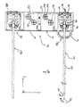
- the FIG. 1 shows an ultrasonic cleaning device 1, which comprises a trough 2, which can be filled with a liquid.
- a trough 2 On the underside 3 of the tub are sound transmission elements (not shown), which transmit ultrasound to the inner walls of the tub 2 and so transmit ultrasonic waves in the liquid contained in the tub 2.
- sound transmission elements not shown
- the illustrated ultrasonic cleaning device is a built-in device, which is embedded in the surface of a tray 4.
- the additional device 100 comprises a frame 110, which projects beyond the upper edge of the trough 2.
- an adapter bank 120 At the lower end of the frame 110 is an adapter bank 120, which is arranged such that it can be inserted into the trough 2.
- the control and / or operating unit 200 can via a cable connection with be connected to a drive of the additional device.
- the cable is both a motor of the drive supplied with electricity, as well as driven, so that performs these movements.
- the control of the control and operating unit 200 by a user is made via the touch-sensitive display 210. It may be a capacitive or resistive touch-sensitive screen.
- a control board 230 having processors and memory units disposed thereon.
- the frame 110 comprises two grip parts 111 and 112 extending in the xz-plane, by means of which the auxiliary device 100 can be put out of and into the trough.
- the handles 111 and 112 are rails 113 and 114, which connect the two handles together.
- an adapter bank 120 is additionally arranged, which in the present exemplary embodiment comprises four adapters 121 to 124.
- the frame 110 may be made of metal or a plastic. It is also possible that, for example, the handles 111 and 112 made of metal and the rails 113 and 114 are made of a plastic. On the rails 113, 114 are also elevations 115 and 116, so that the frame is only pointwise in contact with the tub. The constant width of the frame is ensured by cross struts 117.
- the adapter bank 120 comprises a housing 130 which at the same time forms the housing for the four adapters 121 to 124.
- the housing is made of plastic and includes openings 125 which allow liquid in the tub to enter the interior of the housing 130.
- the adapter 121 comprises at least one coupling element 140 or 142 which is movable relative to the housing.
- the coupling elements may be made of plastic, stainless steel, titanium, other medical materials or other chemically resistant or water-resistant materials and project over the surface 131 of the housing 130 in z Direction.
- the movable coupling elements 140 and 142 are resilient in the z-direction stored.
- the coupling elements sit on one in the representation of the FIG. 2 unrecognizable shaft, which is driven by a mechanical, hydraulic or pneumatic.
- the shaft is anchored to a bottom of the housing and has a spring mechanism which allows suspension of the coupling element in the z-direction. That is, the coupling element can be pressed in the negative z-direction at least by the height at which it projects beyond the surface 131.
- a drive 160 is also arranged, which is arranged at the upper end in the region of the handle 112. This comprises a housing 161, in which there is an electric motor in this case.
- the housing 161 is connected in the present example via a strut 118 to the adapter bank.
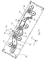
- FIG. 3a is a plan view of the adapter bank of FIG. 1 and 2 shown in the xy plane.
- a fixation device 150 as well as two medical instruments 170 and 170 'can be seen, so that the interaction between the instrument 170 and the coupling elements can be explained in more detail.
- the instrument 170 includes a shaft 172 which is rotatable along the axis of the shaft in the direction R.
- the shaft 172 also includes at its distal end a movable tip 173, which is rotatable in the yz plane in the direction B.
- the instrument comprises a housing (which is cut open in this plan view) which, inter alia, comprises four mechanisms 176, 178, 180 and 182.
- a rotation of the element 176 causes an opening in the direction 02
- the mechanism 180 causes a rotation in the direction O1
- the element 178 a rotation in the direction R
- the element 182 a rotation in the direction B.
- each includes the adapter of the adapter bank 120 has two movable coupling elements 144 and 146, which in each case comprises two grooves 148 extending in a crosswise manner relative to each other.
- the grooves are selected such that a pin located on the underside of the mechanisms 176 to 182, not shown, can be held in a form-fitting manner in the grooves.
- a movement of the coupling element 144 for example, into a movement of the mechanism 182 and thus an active movement of the tip 173 in the direction B is implemented.
- the mechanisms can each be rotated over a range of movement, ie a certain length, in order to pass from a first to a second stop.
- the first and second stops correspond to the extreme positions of the part of the instrument which is moved by the mechanism.
- the pins on the underside of the mechanism of the medical instrument first press against the region of the coupling element 144 or 146 which delimits the grooves.
- the coupling element is pressed in the z direction down.
- the pin of the mechanism now slips along the surface bounding the grooves 148 until it engages in one of the grooves.
- the pressure on the spring-mounted coupling element 144 is reduced and the coupling element is pressed in the positive z-direction upwards.
- the positive connection between the groove and the pin of the medical instrument is brought about.
- the movement of the distal part of the medical instrument may be such that the coupling element 144 is initially moved by certain clockwise and then by the same angle counterclockwise, thereby an active movement is transmitted to the medical instrument, so that the distal tip 173 can be bent over an angular range of for example 180 ° and the arms of the clamp over a range of also almost 180 ° can be moved.
- the grooves 148 serve inter alia also the fixation of the medical instrument.
- holes or webs can take over the function of the grooves.
- the shape of the fixing element, which is arranged on the coupling element, thus essentially depends on the mechanics of the medical instruments. If the medical instruments have pins, grooves or holes are preferable. Have these holes or grooves, webs or pins are used on the movable coupling element.
- each adapter has additional fixing aids.
- a recess 152 is present, which is embedded in the surface 131. In this area are in the illustrated medical instrument electrical contacts, which protrude slightly above the bottom of the medical instrument. These can be aligned in the recess 152, so that the positioning of the medical instrument in the adapter is simplified.
- a web 154 is present, which also engages in a corresponding recess in the underside of the medical instrument.
- the fixing device 150 also has as in the FIG. 3b recognizable, a latching lug 158 which engages in a corresponding recess of the medical instrument.
- the fixing device 150 comprises an undercut 160, which closes in a form-fitting manner with a projection 184 of the medical instrument.
- the fixed in the adapter 121 medical instrument 170 is fixed in its orientation relative to the adapter 121. Only the coupling via the coupling element 144 or 146 and the corresponding mechanism 178 and 182, respectively, causes active movement of the distal end of the medical instrument. Other parts or areas of the medical instrument are not moved by the coupling elements.
- the fixing device 150 also comprises a handle 156, which is pulled in the negative ⁇ -direction, the medical instrument 170 releases. This condition can be recognized, for example, in the adapter 124.
- the fixing element 150 comprises a stop, so that this can only be pulled over the half of the length of the adapter, for example, and then remains in the adapter. Also in this position, a release of the medical instrument from the adapter is possible.
- Both the adapter housing 130 and the coupling element 144, 146 and the gear train, not shown, which sits in the housing 130 may be made of plastic or metal.
- the fixing device 150 may also be made of plastic or metal.
- a flushing device 240 can be seen, which comprises hoses 242/244 for a suction flush and / or a pressure flush.
- the hoses or the flushing liquid located therein are sucked or pressed by means of a pump 246.
- the hoses 242 and 244 can, for example, with the in the FIG. 3a shown rinse adapter 190 (which is connected to the medical instrument 170), which connects the lumen of the shaft 172 with the hose.
- a program can be initiated via the touch-sensitive display, which allows a pressure or suction flushing of the lumen of the shaft 172.
- the controller 230 is programmed so that the single pump 246 can pressurize all four instruments located in the adapter bank 120 with a suction or pressure purge.
- the suction or pressure channel by channel that is, one adapter after another, carried out so that it can be determined at least for the suction irrigation, whether the lumen of the shaft of the medical instrument is clogged or not.
- the switching between suction and pressure operation is performed by a suction and pressure switch 248, the channel switching, ie the channel Actuation takes place in a channel switch, not shown.
- the blockage can be determined via the flow passing through the pump or the pressure associated therewith. Part of this technology is also used in the Sonomic products.
- the control device 230 includes, as mentioned above, a processor and a memory unit.
- the memory unit stores various programs for moving the instruments. Thus, depending on the inserted instrument, a program can be selected which defines the corresponding angular range of rotation of the instrument and the coupling elements to be controlled. These programs are initialized via the processor and the processor takes control of the drive so that it initiates the movement of the coupling elements according to the program.
- connection 250 is also a connection 250 recognizable, via which a connection between the drive 160 of the additional device 100 can take place with the control and / or control unit 200.
- a connection can be a copper connection.
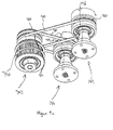
- Fig. 5a are shown in the housing 120 arranged components of the drive 160 in more detail.
- the perspective shown is looking from the bottom of the housing in the z direction.
- a mechanism 300 which includes, inter alia, four shaft elements 301-304.
- the shaft element 301 is connected directly to the coupling rod 162, so that a movement of the motor arranged in the housing 161 is transmitted directly to the shaft element 301.
- the shaft element 301 is coupled to the shaft elements 302 and 303 by means of a first force transmission element 310 in the form of a toothed belt, so that a rotational movement of the shaft element 301 to the left causes a corresponding movement of the shaft elements 302 and 303.
- the toothed belt is guided a deflection element 305.
- the shaft member 301 is further coupled to the shaft member 304 via another first power transmission member 320. Also, this power transmission element 320 is guided over deflecting elements 306 and 307.
- the first power transmission elements 310 and 320 are formed in the present example as a toothed belt, which engage in corresponding teeth 330 of the shaft elements 301-304.
- the timing belt are under a mechanical tension, which further favors the transmission of motion of the shaft elements with each other.
- the first power transmission element may also be a belt without teeth.
- the power transmission element may provide for hydraulic or pneumatic motion transmission.
- the teeth of the shaft members may be similar to turbine blades, such that liquid or air moved by the shaft member 301 without a (closed) channel causes movement of the further shaft members 302-304.
- the shaft elements are cylindrical and are rotatably mounted on a shaft.
- the shaft 308 can be seen.
- a bearing for example, a sliding or ball bearings can be provided.
- Each shaft element 301-304 is coupled to two coupling elements each.
- the shaft element 302 is coupled to the coupling elements 144 and 146 via a respective second force transmission element 340 and 341 in the form of a respective round belt.
- provided with the grooves 148 surfaces of the coupling elements 144 and 148 protrude from openings of the housing 120 as in, for example, in Fig. 2 is shown.
- the shaft elements do not protrude out of the surface through their own openings.
- the round belt runs in a recess of the shaft member and the coupling element. This is for example in the FIG. 5c shown.
- the second power transmission element 340 runs in a groove 350 of the shaft element and a groove 360 of the coupling element.
- the second power transmission element 341 runs in a groove 351 of the shaft element and a groove 361 of the coupling element.
- a mechanic of a robotic medical instrument can engage in, for example, the groove 148 (or a corresponding groove of another coupling element). In this way, movement of the motor, via the coupling rod 162, the shaft elements 301-304 and the second force transmission elements transferred to the coupling elements and the distal ends of the example instruments 170 and 170 'are moved and the shaft of the instrument is rotated.
- a first and a second coupling elements are each coupled to a shaft element via a second force transmission element
- a first coupling element can move independently of the second coupling element in the sense that slippage of the round belt of the first coupling element has no influence on any movement of the first coupling element second coupling element has. In this way it is not important that the distal, movable ends of the instruments are in a predetermined position prior to insertion into an adapter.
- the motor is rotated in each case one direction of rotation for a distance corresponding to the full rotation circumference of the mechanics of the instrument, or the full maximum rotational range of the various mechanisms (each for moving a different Part of the instrument, such as the rotation of the shaft or the rotation of the distal end or various instruments inserted into various adapter of the adapter bank instruments), it can be ensured that all inserted into an adapter instruments are moved over their full range of motion, regardless of the starting position the mechanics of the instruments.
- the mechanics are temporarily moved simultaneously, ie not moved in succession, as long as the mechanism moved by the coupling element has not yet reached the stop.
- a rotational movement in the opposite direction over at least the previous route is performed. From this point on, a synchronization of the movements of the inserted instruments can be guaranteed.
- the duration of the first rotation and the subsequent second rotation, i. the first and second time periods are chosen to be longer than the time it takes for one of the moving mechanics at the given or set speed of the drive to travel through its respective full range of motion.
- the duration of the movement in the first or second direction can be reduced.
- the additional device is during cleaning in a liquid which can penetrate into the housing 120 and thus the movement resistance from which slippage is possible to raise or lower.
- a channel which causes a coupling of the shaft member with the coupling element comprise a pressure relief valve. Bring now a mechanics of an instrument one Resistance to movement on the coupling element, the pressure in the channel increases and the valve opens when a pressure is exceeded.
- the movement of the shaft member no longer leads to a movement of the coupling element, since the force applied to the coupling element resistance to movement is too high and exceeds a predetermined resistance to movement.
- the predetermined resistance to movement is chosen such that a mechanism of an instrument to be cleaned is not damaged.
- a shaft element comprises two rows of teeth for each one toothed belt or two grooves for each round belt. In other embodiments, the number may be varied in each case.
- the coupling element can have a functional division into two parts. It can thus be provided that an upper part of the coupling element that can be brought into engagement with the instrument is connected to a second part of the coupling element which is coupled to the second force transmission element such that when the upper part of the coupling element is acted upon by a movement resistance a movement decoupling of the upper and lower part of the coupling element takes place, in the sense that the two parts are still connected to each other (for example, via a bearing of the shaft), but can be rotated independently, as soon as the upper part undergoes a resistance movement.
- the upper and lower parts may, for example, each comprise mutually corresponding elevations and depressions (eg: wave pattern), which have a positive connection in the direction of power transmission, wherein the positive connection can be canceled by applying the predetermined resistance to movement and the two parts can be rotated against each other.
- the upper and the lower part should be adjustable in height relative to one another, for example along a bearing shaft.
- the upper and the lower part are thus connected to each other via a coupling, wherein the clutch comprises an idling, so that when subjected to the upper part with a resistance to movement the clutch goes into neutral and a movement of the upper part is decoupled from the lower part.
- the feature that the movement of the shaft member is not transmitted to the coupling member may also be expressed by providing a coupling between the second power transmission member and the coupling member which changes into an idling condition by applying the movement of the coupling member.
- a tub 400 is shown in which a non-drawn additional device for fixing medical instruments with four inserted instruments 401-404 is arranged.
- the accessory device may be the accessory device 100 described in this application.
- the position of the instruments 401-404 is predetermined by the auxiliary device.
- ultrasonic transducers 407-411 are located at the bottom of the tub 405 and on the tub wall 406 at the bottom of the tub 405 and on the tub wall 406. Since the selected plan view is on the tub from the outside into the tub interior, arranged on the outside of the tub bottom and the tub wall ultrasonic transducers are shown hatched, since they are actually not visible from the selected perspective. In this case, the ultrasonic transducers 407-410 are located at the bottom of the tub and the ultrasonic transducers 411 are located at the tub wall.
- the ultrasound transducer 407 is located just below the distal tip or in the immediate vicinity of the distal tip of the instrument 401.
- the ultrasonic transducers 408 and 409 are disposed below the shaft of the instrument.
- the ultrasonic transducer 410 is located below the adapter 412 of the instrument.
- the adapter is further sonicated by the arranged on the tub wall ultrasonic transducer 411, which is located at the height of the instrument, preferably at the level of the flushing connections of the instrument.
- Below or on the side of the other instruments 402-404 are further ultrasonic transducers 413, which analog are arranged to the ultrasonic transducers 407-411.
- the distance between the ultrasonic transducers 407-410 with each other can be uniform.
- the tub 400 is shown with an alternative attachment (not shown) for holding MIC instruments 421-424.
- the arrangement of the ultrasonic transducers is also such that at least one ultrasonic transducer 427 is arranged in the region of the distal tip of the instrument.
Landscapes
- Health & Medical Sciences (AREA)
- Surgery (AREA)
- Life Sciences & Earth Sciences (AREA)
- Heart & Thoracic Surgery (AREA)
- Pathology (AREA)
- Oral & Maxillofacial Surgery (AREA)
- Engineering & Computer Science (AREA)
- Biomedical Technology (AREA)
- Nuclear Medicine, Radiotherapy & Molecular Imaging (AREA)
- Medical Informatics (AREA)
- Molecular Biology (AREA)
- Animal Behavior & Ethology (AREA)
- General Health & Medical Sciences (AREA)
- Public Health (AREA)
- Veterinary Medicine (AREA)
- Surgical Instruments (AREA)
Priority Applications (1)
| Application Number | Priority Date | Filing Date | Title |
|---|---|---|---|
| US14/459,148 US9974614B2 (en) | 2013-08-16 | 2014-08-13 | Drive and auxiliary device for ultrasound cleaning apparatus |
Applications Claiming Priority (1)
| Application Number | Priority Date | Filing Date | Title |
|---|---|---|---|
| DE202013007537.6U DE202013007537U1 (de) | 2013-08-16 | 2013-08-16 | Antrieb und Zusatzvorrichtung für Ultraschall-Reinigungsgeräte |
Publications (2)
| Publication Number | Publication Date |
|---|---|
| EP2837353A1 true EP2837353A1 (fr) | 2015-02-18 |
| EP2837353B1 EP2837353B1 (fr) | 2015-09-30 |
Family
ID=49911286
Family Applications (1)
| Application Number | Title | Priority Date | Filing Date |
|---|---|---|---|
| EP13199128.3A Active EP2837353B1 (fr) | 2013-08-16 | 2013-12-20 | Entraînement et dispositif supplémentaire pour appareils de nettoyage à ultrasons |
Country Status (2)
| Country | Link |
|---|---|
| EP (1) | EP2837353B1 (fr) |
| DE (1) | DE202013007537U1 (fr) |
Cited By (3)
| Publication number | Priority date | Publication date | Assignee | Title |
|---|---|---|---|---|
| DE202015106167U1 (de) | 2015-11-13 | 2017-02-16 | BANDELIN patent GmbH & Co. KG | Bewegungsvorrichtung sowie System zur Reinigung von medizinischen Instrumenten |
| WO2018016942A1 (fr) * | 2016-07-21 | 2018-01-25 | P.M.T. Partners Medische Techniek B.V. | Insert conçu pour être disposé dans un dispositif de nettoyage d'instruments médicaux |
| US10648730B1 (en) | 2017-05-08 | 2020-05-12 | Cenorin, Llc | Medical implement drying apparatus |
Families Citing this family (2)
| Publication number | Priority date | Publication date | Assignee | Title |
|---|---|---|---|---|
| CH711143A2 (de) * | 2015-05-18 | 2016-11-30 | Luciene Moreira Petri Martins | Apparat zum Desinfizieren medizinischer Instrumente. |
| CN112451026B (zh) * | 2020-12-07 | 2021-10-08 | 咸宁市中心医院 | 用于穿刺介入手术压迫设备 |
Citations (4)
| Publication number | Priority date | Publication date | Assignee | Title |
|---|---|---|---|---|
| US5711921A (en) * | 1996-01-02 | 1998-01-27 | Kew Import/Export Inc. | Medical cleaning and sterilizing apparatus |
| US20110132404A1 (en) * | 2009-03-16 | 2011-06-09 | Lutz Todd M | Method and apparatus for cleaning of laparoscopic surgical instruments |
| WO2012098732A1 (fr) * | 2011-01-18 | 2012-07-26 | シャープ株式会社 | Appareil de nettoyage et procédé de nettoyage |
| WO2012148266A1 (fr) * | 2011-04-29 | 2012-11-01 | P.M.T. Partners Medische Techniek B.V. | Dispositif d'actionnement destiné à actionner un instrument médical dans une machine de nettoyage et de désinfection |
-
2013
- 2013-08-16 DE DE202013007537.6U patent/DE202013007537U1/de not_active Expired - Lifetime
- 2013-12-20 EP EP13199128.3A patent/EP2837353B1/fr active Active
Patent Citations (5)
| Publication number | Priority date | Publication date | Assignee | Title |
|---|---|---|---|---|
| US5711921A (en) * | 1996-01-02 | 1998-01-27 | Kew Import/Export Inc. | Medical cleaning and sterilizing apparatus |
| US20110132404A1 (en) * | 2009-03-16 | 2011-06-09 | Lutz Todd M | Method and apparatus for cleaning of laparoscopic surgical instruments |
| WO2012098732A1 (fr) * | 2011-01-18 | 2012-07-26 | シャープ株式会社 | Appareil de nettoyage et procédé de nettoyage |
| EP2666427A1 (fr) * | 2011-01-18 | 2013-11-27 | Sharp Kabushiki Kaisha | Appareil de nettoyage et procédé de nettoyage |
| WO2012148266A1 (fr) * | 2011-04-29 | 2012-11-01 | P.M.T. Partners Medische Techniek B.V. | Dispositif d'actionnement destiné à actionner un instrument médical dans une machine de nettoyage et de désinfection |
Cited By (7)
| Publication number | Priority date | Publication date | Assignee | Title |
|---|---|---|---|---|
| DE202015106167U1 (de) | 2015-11-13 | 2017-02-16 | BANDELIN patent GmbH & Co. KG | Bewegungsvorrichtung sowie System zur Reinigung von medizinischen Instrumenten |
| EP3167839A3 (fr) * | 2015-11-13 | 2017-08-02 | BANDELIN patent GmbH & Co. KG | Mécanisme de mouvement et système de nettoyage d'instruments médicaux |
| US10299667B2 (en) | 2015-11-13 | 2019-05-28 | BANDELIN patent GmbH & Co. KG | Movement device as well as system for cleaning medical instruments |
| EP3510964A1 (fr) * | 2015-11-13 | 2019-07-17 | BANDELIN patent GmbH & Co. KG | Mécanisme de mouvement et système de nettoyage d'instruments médicaux |
| WO2018016942A1 (fr) * | 2016-07-21 | 2018-01-25 | P.M.T. Partners Medische Techniek B.V. | Insert conçu pour être disposé dans un dispositif de nettoyage d'instruments médicaux |
| US10648730B1 (en) | 2017-05-08 | 2020-05-12 | Cenorin, Llc | Medical implement drying apparatus |
| US11054183B2 (en) | 2017-05-08 | 2021-07-06 | Cenorin, Llc | Medical implement drying apparatus |
Also Published As
| Publication number | Publication date |
|---|---|
| DE202013007537U1 (de) | 2014-11-17 |
| EP2837353B1 (fr) | 2015-09-30 |
Similar Documents
| Publication | Publication Date | Title |
|---|---|---|
| EP3586783B1 (fr) | Support de trocart | |
| DE69635050T2 (de) | Chirurgischer manipulator für ein ferngesteuertes robotersystem | |
| EP2837353B1 (fr) | Entraînement et dispositif supplémentaire pour appareils de nettoyage à ultrasons | |
| DE102011011662B4 (de) | Geschirrspülmaschine mit einem Türverschluss | |
| EP1649816B1 (fr) | Instrument endoscopique déviable | |
| DE69636220T2 (de) | Endoskopisches biopsieinstrument mit verbesserter beisswirkung | |
| DE60130512T2 (de) | Greifzange für Stab | |
| DE112005002849B4 (de) | Robotergelenkstruktur und Roboterfinger | |
| DE60036946T2 (de) | Vorrichtung mit parallelen backen zur verwendung mit einer elektromechanischen steuerungsvorrichtung | |
| EP3167839B1 (fr) | Mécanisme de mouvement et système de nettoyage d'instruments médicaux | |
| DE102020211137A1 (de) | Lösbares endoskop mit einem einstellbaren biegewinkel | |
| EP2941211B1 (fr) | Poignée chirurgicale pour un outil à tige tubulaire | |
| DE102007008099A1 (de) | Schlauchanordnung für ein Endoskop | |
| EP2153793A2 (fr) | Dispositif de manipulation pour un instrument chirurgical et instrument chirurgical | |
| WO2014140100A2 (fr) | Instrument chirurgical | |
| DE202008001675U1 (de) | Zerlegbares chirurgisches Instrument | |
| WO2017194562A1 (fr) | Dispositif de retenue pour un anneau de suture | |
| DE102020211128A1 (de) | Endoskop mit einer funktion zur verhinderung einer kettenverklemmung | |
| DE112018003556T5 (de) | Mit einer irrigationsfunktion ausgestattete saugvorrichtung | |
| WO2018185546A1 (fr) | Endoscope comprenant une tête d'endoscope et un levier d'albarran pouvant être agencé sur la tête d'endoscope et en être séparé | |
| DE60131466T2 (de) | System für die ophthalmologische chirurgie | |
| EP2837352A1 (fr) | Dispositif supplémentaire pour appareils de nettoyage à ultrasons, dispositif de commande pour un appareil à ultrasons et procédé de déplacement actif d'au moins une zone d'un instrument médical | |
| WO2011120642A1 (fr) | Instrument chirurgical | |
| DE102016001271A1 (de) | Transporteur eines Resektoskopes | |
| DE112011101691B4 (de) | Chirurgische medizinische Vorrichtung |
Legal Events
| Date | Code | Title | Description |
|---|---|---|---|
| 17P | Request for examination filed |
Effective date: 20140819 |
|
| AK | Designated contracting states |
Kind code of ref document: A1 Designated state(s): AL AT BE BG CH CY CZ DE DK EE ES FI FR GB GR HR HU IE IS IT LI LT LU LV MC MK MT NL NO PL PT RO RS SE SI SK SM TR |
|
| PUAI | Public reference made under article 153(3) epc to a published international application that has entered the european phase |
Free format text: ORIGINAL CODE: 0009012 |
|
| 17Q | First examination report despatched |
Effective date: 20150202 |
|
| GRAP | Despatch of communication of intention to grant a patent |
Free format text: ORIGINAL CODE: EPIDOSNIGR1 |
|
| INTG | Intention to grant announced |
Effective date: 20150513 |
|
| GRAS | Grant fee paid |
Free format text: ORIGINAL CODE: EPIDOSNIGR3 |
|
| GRAA | (expected) grant |
Free format text: ORIGINAL CODE: 0009210 |
|
| AK | Designated contracting states |
Kind code of ref document: B1 Designated state(s): AL AT BE BG CH CY CZ DE DK EE ES FI FR GB GR HR HU IE IS IT LI LT LU LV MC MK MT NL NO PL PT RO RS SE SI SK SM TR |
|
| REG | Reference to a national code |
Ref country code: CH Ref legal event code: EP Ref country code: GB Ref legal event code: FG4D Free format text: NOT ENGLISH |
|
| REG | Reference to a national code |
Ref country code: AT Ref legal event code: REF Ref document number: 751919 Country of ref document: AT Kind code of ref document: T Effective date: 20151015 |
|
| REG | Reference to a national code |
Ref country code: IE Ref legal event code: FG4D Free format text: LANGUAGE OF EP DOCUMENT: GERMAN |
|
| REG | Reference to a national code |
Ref country code: DE Ref legal event code: R096 Ref document number: 502013001265 Country of ref document: DE |
|
| REG | Reference to a national code |
Ref country code: CH Ref legal event code: NV Representative=s name: DR. LUSUARDI AG, CH |
|
| REG | Reference to a national code |
Ref country code: FR Ref legal event code: PLFP Year of fee payment: 3 |
|
| REG | Reference to a national code |
Ref country code: DE Ref legal event code: R082 Ref document number: 502013001265 Country of ref document: DE Representative=s name: PFENNING, MEINIG & PARTNER MBB PATENTANWAELTE, DE |
|
| PG25 | Lapsed in a contracting state [announced via postgrant information from national office to epo] |
Ref country code: LV Free format text: LAPSE BECAUSE OF FAILURE TO SUBMIT A TRANSLATION OF THE DESCRIPTION OR TO PAY THE FEE WITHIN THE PRESCRIBED TIME-LIMIT Effective date: 20150930 Ref country code: FI Free format text: LAPSE BECAUSE OF FAILURE TO SUBMIT A TRANSLATION OF THE DESCRIPTION OR TO PAY THE FEE WITHIN THE PRESCRIBED TIME-LIMIT Effective date: 20150930 Ref country code: LT Free format text: LAPSE BECAUSE OF FAILURE TO SUBMIT A TRANSLATION OF THE DESCRIPTION OR TO PAY THE FEE WITHIN THE PRESCRIBED TIME-LIMIT Effective date: 20150930 Ref country code: NO Free format text: LAPSE BECAUSE OF FAILURE TO SUBMIT A TRANSLATION OF THE DESCRIPTION OR TO PAY THE FEE WITHIN THE PRESCRIBED TIME-LIMIT Effective date: 20151230 Ref country code: GR Free format text: LAPSE BECAUSE OF FAILURE TO SUBMIT A TRANSLATION OF THE DESCRIPTION OR TO PAY THE FEE WITHIN THE PRESCRIBED TIME-LIMIT Effective date: 20151231 |
|
| REG | Reference to a national code |
Ref country code: NL Ref legal event code: MP Effective date: 20150930 |
|
| REG | Reference to a national code |
Ref country code: LT Ref legal event code: MG4D |
|
| PG25 | Lapsed in a contracting state [announced via postgrant information from national office to epo] |
Ref country code: RS Free format text: LAPSE BECAUSE OF FAILURE TO SUBMIT A TRANSLATION OF THE DESCRIPTION OR TO PAY THE FEE WITHIN THE PRESCRIBED TIME-LIMIT Effective date: 20150930 Ref country code: HR Free format text: LAPSE BECAUSE OF FAILURE TO SUBMIT A TRANSLATION OF THE DESCRIPTION OR TO PAY THE FEE WITHIN THE PRESCRIBED TIME-LIMIT Effective date: 20150930 Ref country code: SE Free format text: LAPSE BECAUSE OF FAILURE TO SUBMIT A TRANSLATION OF THE DESCRIPTION OR TO PAY THE FEE WITHIN THE PRESCRIBED TIME-LIMIT Effective date: 20150930 |
|
| PG25 | Lapsed in a contracting state [announced via postgrant information from national office to epo] |
Ref country code: CZ Free format text: LAPSE BECAUSE OF FAILURE TO SUBMIT A TRANSLATION OF THE DESCRIPTION OR TO PAY THE FEE WITHIN THE PRESCRIBED TIME-LIMIT Effective date: 20150930 Ref country code: IS Free format text: LAPSE BECAUSE OF FAILURE TO SUBMIT A TRANSLATION OF THE DESCRIPTION OR TO PAY THE FEE WITHIN THE PRESCRIBED TIME-LIMIT Effective date: 20160130 Ref country code: NL Free format text: LAPSE BECAUSE OF FAILURE TO SUBMIT A TRANSLATION OF THE DESCRIPTION OR TO PAY THE FEE WITHIN THE PRESCRIBED TIME-LIMIT Effective date: 20150930 Ref country code: IT Free format text: LAPSE BECAUSE OF FAILURE TO SUBMIT A TRANSLATION OF THE DESCRIPTION OR TO PAY THE FEE WITHIN THE PRESCRIBED TIME-LIMIT Effective date: 20150930 Ref country code: ES Free format text: LAPSE BECAUSE OF FAILURE TO SUBMIT A TRANSLATION OF THE DESCRIPTION OR TO PAY THE FEE WITHIN THE PRESCRIBED TIME-LIMIT Effective date: 20150930 Ref country code: EE Free format text: LAPSE BECAUSE OF FAILURE TO SUBMIT A TRANSLATION OF THE DESCRIPTION OR TO PAY THE FEE WITHIN THE PRESCRIBED TIME-LIMIT Effective date: 20150930 Ref country code: SK Free format text: LAPSE BECAUSE OF FAILURE TO SUBMIT A TRANSLATION OF THE DESCRIPTION OR TO PAY THE FEE WITHIN THE PRESCRIBED TIME-LIMIT Effective date: 20150930 |
|
| PG25 | Lapsed in a contracting state [announced via postgrant information from national office to epo] |
Ref country code: PT Free format text: LAPSE BECAUSE OF FAILURE TO SUBMIT A TRANSLATION OF THE DESCRIPTION OR TO PAY THE FEE WITHIN THE PRESCRIBED TIME-LIMIT Effective date: 20160201 Ref country code: BE Free format text: LAPSE BECAUSE OF NON-PAYMENT OF DUE FEES Effective date: 20151231 Ref country code: RO Free format text: LAPSE BECAUSE OF FAILURE TO SUBMIT A TRANSLATION OF THE DESCRIPTION OR TO PAY THE FEE WITHIN THE PRESCRIBED TIME-LIMIT Effective date: 20150930 Ref country code: PL Free format text: LAPSE BECAUSE OF FAILURE TO SUBMIT A TRANSLATION OF THE DESCRIPTION OR TO PAY THE FEE WITHIN THE PRESCRIBED TIME-LIMIT Effective date: 20150930 |
|
| REG | Reference to a national code |
Ref country code: DE Ref legal event code: R097 Ref document number: 502013001265 Country of ref document: DE |
|
| PG25 | Lapsed in a contracting state [announced via postgrant information from national office to epo] |
Ref country code: MC Free format text: LAPSE BECAUSE OF FAILURE TO SUBMIT A TRANSLATION OF THE DESCRIPTION OR TO PAY THE FEE WITHIN THE PRESCRIBED TIME-LIMIT Effective date: 20150930 Ref country code: LU Free format text: LAPSE BECAUSE OF FAILURE TO SUBMIT A TRANSLATION OF THE DESCRIPTION OR TO PAY THE FEE WITHIN THE PRESCRIBED TIME-LIMIT Effective date: 20151220 |
|
| PLBE | No opposition filed within time limit |
Free format text: ORIGINAL CODE: 0009261 |
|
| STAA | Information on the status of an ep patent application or granted ep patent |
Free format text: STATUS: NO OPPOSITION FILED WITHIN TIME LIMIT |
|
| PG25 | Lapsed in a contracting state [announced via postgrant information from national office to epo] |
Ref country code: DK Free format text: LAPSE BECAUSE OF FAILURE TO SUBMIT A TRANSLATION OF THE DESCRIPTION OR TO PAY THE FEE WITHIN THE PRESCRIBED TIME-LIMIT Effective date: 20150930 |
|
| 26N | No opposition filed |
Effective date: 20160701 |
|
| REG | Reference to a national code |
Ref country code: IE Ref legal event code: MM4A |
|
| PG25 | Lapsed in a contracting state [announced via postgrant information from national office to epo] |
Ref country code: IE Free format text: LAPSE BECAUSE OF NON-PAYMENT OF DUE FEES Effective date: 20151220 |
|
| PG25 | Lapsed in a contracting state [announced via postgrant information from national office to epo] |
Ref country code: SI Free format text: LAPSE BECAUSE OF FAILURE TO SUBMIT A TRANSLATION OF THE DESCRIPTION OR TO PAY THE FEE WITHIN THE PRESCRIBED TIME-LIMIT Effective date: 20150930 |
|
| REG | Reference to a national code |
Ref country code: FR Ref legal event code: PLFP Year of fee payment: 4 |
|
| PG25 | Lapsed in a contracting state [announced via postgrant information from national office to epo] |
Ref country code: BG Free format text: LAPSE BECAUSE OF FAILURE TO SUBMIT A TRANSLATION OF THE DESCRIPTION OR TO PAY THE FEE WITHIN THE PRESCRIBED TIME-LIMIT Effective date: 20150930 |
|
| PG25 | Lapsed in a contracting state [announced via postgrant information from national office to epo] |
Ref country code: HU Free format text: LAPSE BECAUSE OF FAILURE TO SUBMIT A TRANSLATION OF THE DESCRIPTION OR TO PAY THE FEE WITHIN THE PRESCRIBED TIME-LIMIT; INVALID AB INITIO Effective date: 20131220 Ref country code: CY Free format text: LAPSE BECAUSE OF FAILURE TO SUBMIT A TRANSLATION OF THE DESCRIPTION OR TO PAY THE FEE WITHIN THE PRESCRIBED TIME-LIMIT Effective date: 20150930 |
|
| PG25 | Lapsed in a contracting state [announced via postgrant information from national office to epo] |
Ref country code: MT Free format text: LAPSE BECAUSE OF FAILURE TO SUBMIT A TRANSLATION OF THE DESCRIPTION OR TO PAY THE FEE WITHIN THE PRESCRIBED TIME-LIMIT Effective date: 20150930 |
|
| REG | Reference to a national code |
Ref country code: FR Ref legal event code: PLFP Year of fee payment: 5 |
|
| PG25 | Lapsed in a contracting state [announced via postgrant information from national office to epo] |
Ref country code: SM Free format text: LAPSE BECAUSE OF FAILURE TO SUBMIT A TRANSLATION OF THE DESCRIPTION OR TO PAY THE FEE WITHIN THE PRESCRIBED TIME-LIMIT Effective date: 20150930 |
|
| PG25 | Lapsed in a contracting state [announced via postgrant information from national office to epo] |
Ref country code: MK Free format text: LAPSE BECAUSE OF FAILURE TO SUBMIT A TRANSLATION OF THE DESCRIPTION OR TO PAY THE FEE WITHIN THE PRESCRIBED TIME-LIMIT Effective date: 20150930 |
|
| GBPC | Gb: european patent ceased through non-payment of renewal fee |
Effective date: 20171220 |
|
| PG25 | Lapsed in a contracting state [announced via postgrant information from national office to epo] |
Ref country code: AL Free format text: LAPSE BECAUSE OF FAILURE TO SUBMIT A TRANSLATION OF THE DESCRIPTION OR TO PAY THE FEE WITHIN THE PRESCRIBED TIME-LIMIT Effective date: 20150930 Ref country code: TR Free format text: LAPSE BECAUSE OF FAILURE TO SUBMIT A TRANSLATION OF THE DESCRIPTION OR TO PAY THE FEE WITHIN THE PRESCRIBED TIME-LIMIT Effective date: 20150930 |
|
| PG25 | Lapsed in a contracting state [announced via postgrant information from national office to epo] |
Ref country code: GB Free format text: LAPSE BECAUSE OF NON-PAYMENT OF DUE FEES Effective date: 20171220 |
|
| REG | Reference to a national code |
Ref country code: AT Ref legal event code: MM01 Ref document number: 751919 Country of ref document: AT Kind code of ref document: T Effective date: 20181220 |
|
| PG25 | Lapsed in a contracting state [announced via postgrant information from national office to epo] |
Ref country code: AT Free format text: LAPSE BECAUSE OF NON-PAYMENT OF DUE FEES Effective date: 20181220 |
|
| REG | Reference to a national code |
Ref country code: CH Ref legal event code: U11 Free format text: ST27 STATUS EVENT CODE: U-0-0-U10-U11 (AS PROVIDED BY THE NATIONAL OFFICE) Effective date: 20260101 |
|
| PGFP | Annual fee paid to national office [announced via postgrant information from national office to epo] |
Ref country code: DE Payment date: 20251216 Year of fee payment: 13 |
|
| PGFP | Annual fee paid to national office [announced via postgrant information from national office to epo] |
Ref country code: FR Payment date: 20251223 Year of fee payment: 13 |
|
| PGFP | Annual fee paid to national office [announced via postgrant information from national office to epo] |
Ref country code: CH Payment date: 20260101 Year of fee payment: 13 |