EP2839935A1 - Système de robot - Google Patents
Système de robot Download PDFInfo
- Publication number
- EP2839935A1 EP2839935A1 EP12874699.7A EP12874699A EP2839935A1 EP 2839935 A1 EP2839935 A1 EP 2839935A1 EP 12874699 A EP12874699 A EP 12874699A EP 2839935 A1 EP2839935 A1 EP 2839935A1
- Authority
- EP
- European Patent Office
- Prior art keywords
- robot
- work
- unit
- chuck jaws
- chuck
- Prior art date
- Legal status (The legal status is an assumption and is not a legal conclusion. Google has not performed a legal analysis and makes no representation as to the accuracy of the status listed.)
- Withdrawn
Links
Images


Classifications
-
- B—PERFORMING OPERATIONS; TRANSPORTING
- B25—HAND TOOLS; PORTABLE POWER-DRIVEN TOOLS; MANIPULATORS
- B25J—MANIPULATORS; CHAMBERS PROVIDED WITH MANIPULATION DEVICES
- B25J9/00—Program-controlled manipulators
- B25J9/16—Program controls
- B25J9/1602—Program controls characterised by the control system, structure, architecture
-
- B—PERFORMING OPERATIONS; TRANSPORTING
- B25—HAND TOOLS; PORTABLE POWER-DRIVEN TOOLS; MANIPULATORS
- B25J—MANIPULATORS; CHAMBERS PROVIDED WITH MANIPULATION DEVICES
- B25J9/00—Program-controlled manipulators
- B25J9/0093—Program-controlled manipulators co-operating with conveyor means
-
- B—PERFORMING OPERATIONS; TRANSPORTING
- B25—HAND TOOLS; PORTABLE POWER-DRIVEN TOOLS; MANIPULATORS
- B25J—MANIPULATORS; CHAMBERS PROVIDED WITH MANIPULATION DEVICES
- B25J15/00—Gripping heads and other end effectors
- B25J15/0028—Gripping heads and other end effectors with movable, e.g. pivoting gripping jaw surfaces
-
- B—PERFORMING OPERATIONS; TRANSPORTING
- B25—HAND TOOLS; PORTABLE POWER-DRIVEN TOOLS; MANIPULATORS
- B25J—MANIPULATORS; CHAMBERS PROVIDED WITH MANIPULATION DEVICES
- B25J15/00—Gripping heads and other end effectors
- B25J15/0047—Gripping heads and other end effectors for internally gripping hollow or recessed objects
-
- B—PERFORMING OPERATIONS; TRANSPORTING
- B25—HAND TOOLS; PORTABLE POWER-DRIVEN TOOLS; MANIPULATORS
- B25J—MANIPULATORS; CHAMBERS PROVIDED WITH MANIPULATION DEVICES
- B25J15/00—Gripping heads and other end effectors
- B25J15/08—Gripping heads and other end effectors having finger members
- B25J15/10—Gripping heads and other end effectors having finger members with three or more finger members
- B25J15/103—Gripping heads and other end effectors having finger members with three or more finger members for gripping the object in three contact points
-
- B—PERFORMING OPERATIONS; TRANSPORTING
- B25—HAND TOOLS; PORTABLE POWER-DRIVEN TOOLS; MANIPULATORS
- B25J—MANIPULATORS; CHAMBERS PROVIDED WITH MANIPULATION DEVICES
- B25J17/00—Joints
- B25J17/02—Wrist joints
-
- B—PERFORMING OPERATIONS; TRANSPORTING
- B25—HAND TOOLS; PORTABLE POWER-DRIVEN TOOLS; MANIPULATORS
- B25J—MANIPULATORS; CHAMBERS PROVIDED WITH MANIPULATION DEVICES
- B25J9/00—Program-controlled manipulators
- B25J9/16—Program controls
- B25J9/1612—Program controls characterised by the hand, wrist, grip control
-
- Y—GENERAL TAGGING OF NEW TECHNOLOGICAL DEVELOPMENTS; GENERAL TAGGING OF CROSS-SECTIONAL TECHNOLOGIES SPANNING OVER SEVERAL SECTIONS OF THE IPC; TECHNICAL SUBJECTS COVERED BY FORMER USPC CROSS-REFERENCE ART COLLECTIONS [XRACs] AND DIGESTS
- Y10—TECHNICAL SUBJECTS COVERED BY FORMER USPC
- Y10S—TECHNICAL SUBJECTS COVERED BY FORMER USPC CROSS-REFERENCE ART COLLECTIONS [XRACs] AND DIGESTS
- Y10S901/00—Robots
- Y10S901/02—Arm motion controller
-
- Y—GENERAL TAGGING OF NEW TECHNOLOGICAL DEVELOPMENTS; GENERAL TAGGING OF CROSS-SECTIONAL TECHNOLOGIES SPANNING OVER SEVERAL SECTIONS OF THE IPC; TECHNICAL SUBJECTS COVERED BY FORMER USPC CROSS-REFERENCE ART COLLECTIONS [XRACs] AND DIGESTS
- Y10—TECHNICAL SUBJECTS COVERED BY FORMER USPC
- Y10S—TECHNICAL SUBJECTS COVERED BY FORMER USPC CROSS-REFERENCE ART COLLECTIONS [XRACs] AND DIGESTS
- Y10S901/00—Robots
- Y10S901/30—End effector
- Y10S901/31—Gripping jaw
Definitions
- An embodiment of the disclosure relates to a robot system.
- Such robot systems include, for example, one in which a plurality of dedicated robots according to the kinds of members to be handled is placed in the middle of a work transport lane, and members are sequentially assembled to the work by the dedicated robots (see, for example, Patent Literature 1).
- Patent Literature 1 Japanese Patent Application Laid-open No. 2003-324909
- the above-mentioned robot system has a problem that dedicated robots need to be placed according to the kinds of members, and it is likely to give rise to an increase in the size of the system.
- An aspect of an embodiment has been made considering the above, and an object thereof is to provide a robot system that can process a work efficiently without increasing the size of a system.
- a robot system includes a robot, a determination unit, a selection unit, and an instruction unit.
- the robot includes a robot hand having three or more chuck jaws that open and close.
- the determination unit configured to obtain information on a member formed including a substantially ring shape and determine a state of the member.
- the selection unit configured to select whether to hold the member with the chuck jaws from an inner peripheral side or an outer peripheral side based on the determination result of the determination unit.
- the instruction unit configured to instruct the robot to perform operations of transporting the member while holding the member with the chuck jaws based on the selection result of the selection unit, and assembling a predetermined processed product using the member.
- An aspect of an embodiment can process a work efficiently without increasing the size of a system.
- a work that is a product to be processed is a bracket to be mounted on a motor.
- a description is given below taking an example of a robot system that performs processing to mount a bearing and a retaining ring as intermediate members on the bracket.
- a bracket may be described as a "work" below.
- FIG. 1 is a schematic plan view illustrating an entire configuration of a robot system 1 according to the embodiment.
- a three-dimensional orthogonal coordinate system including a z axis in which a vertically upward direction is set as the positive direction is illustrated to facilitate the understanding of the description.
- the orthogonal coordinate system may also be illustrated in other drawings used in the following description.
- the positive direction of the x axis is defined as the front of the robot system 1.
- a reference numeral is assigned only to one of them, and the assignment of reference numerals to the others may be omitted. In such a case, the one to which the reference numeral has been assigned and the others are assumed to have a similar configuration.
- the robot system 1 includes a cell 2 forming a cuboid work space. Moreover, the robot system 1 includes a work supply unit 3 installed side by side to the cell 2. The cell 2 communicates with the work supply unit 3 via an opening whose illustration is omitted.
- the work supply unit 3 is partitioned into a robot side area 31 and a worker side area 32. Both are connected by a guide rail 33.
- a transport pallet 40 is slidably provided on the guide rail 33.
- the transport pallet 40 is a housing unit for works W before and after processing.
- the transport pallet 40 includes a stocker 41.
- the stockers 41 house the works W on multiple stages.
- the transport pallet 40 includes handle portions 42 and 43 formed in shapes that a robot 10 described below can hold using a robot hand (hereinafter described as the "hand").
- the robot 10 slides the transport pallet 40 to the robot side area 31 or the worker side area 32 while holding the handle portions 42 and 43. This point is described below in a description with FIG. 8 .
- FIG. 1 illustrates a state where the transport pallet 40 has been slid to the robot side area 31.
- the robot 10 takes out the work W before processing from the stocker 41 and stores the work W after processing in the stocker 41.
- the worker takes out the work W after processing from the stocker 41 and stores the work W before processing in the stocker 41.
- the robot system 1 includes, in the cell 2, the robot 10, a controller 20, a workbench 50, a first part supply unit 60, a second part supply unit 70, dry shelving 80, an adhesive application unit 90, and a camera unit 100.
- the robot 10 is a single-arm manipulator that operates to process the work W at the operation instruction of the controller 20, and has the hand described below at a mobile terminal portion of the arm (hereinafter described as the "arm").
- the configuration of the robot 10 is described in detail below with reference to FIGs. 2 to 4B .
- the controller 20 is connected to various devices including the robot 10 in the cell 2, and a higher-level device such as a host computer in such a manner as to be able to communicate.
- the controller 20 is a controller that controls the operation of various devices connected, and is configured including various control equipment, arithmetic processing units, storage devices, and the like. The configuration of the controller 20 is described in detail below with reference to FIG. 5 .
- FIG. 1 illustrates the controller 20 having one casing.
- the configuration is not limited to this, but may include, for example, a plurality of casings associated respectively with various devices targeted for control.
- the controller 20 may be placed outside the cell 2.
- the workbench 50 is a workbench used when the robot 10 performs a processing operation on the work W.
- the workbench 50 includes a first workbench 51, a second workbench 52, and a jig storage unit 53.
- the first workbench 51 and the second workbench 52 are used, depending on the kind of work W.
- the jig storage unit 53 is a unit for storing jigs J1 and J2 used for processing operations of the robot 10.
- the jigs J1 and J2 are described in detail in a series of operations of the robot 10 that is described below with reference to FIGs. 7A to 7H .
- the first part supply unit 60 is a unit that supplies, into the cell 2, a bearing (hereinafter described as the "first part") being an intermediate member to be mounted on the bracket (that is, the work W).
- the second part supply unit 70 is a unit that supplies, into the cell 2, a retaining ring (hereinafter described as the "second part") also being an intermediate member.
- the dry shelving 80 is a housing unit temporary for drying the work W where the first and second parts have been mounted and an adhesive has been applied to the mounting locations, for a predetermined period of time.
- the dry shelving 80 includes multiple shelves along the z axis direction. Each shelf includes a handle portion 81 in a similar shape to those of the handle portions 42 and 43.
- the robot 10 can perform a drawing operation or storing operation by sliding each shelf of the dry shelving 80 while holding the handle portion 81 with the hand. The point is described in detail below in a description with FIG. 7G .
- the adhesive application unit 90 is a unit that applies an adhesive to the mounting locations of the first and second parts.
- the camera unit 100 is an imaging device having a predetermined imaging area. It is unclear from FIG. 1 , but the adhesive application unit 90 and the camera unit 100 are assumed to be suspended above the robot 10 from a ceiling section of the cell 2.
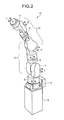
- FIG. 2 is a schematic perspective view illustrating the configuration of the robot 10.
- the robot 10 is a single-arm multi-axis robot. Specifically, the robot 10 includes a first arm section 11, a second arm section 12, a third arm section 13, a fourth arm section 14, a fifth arm section 15, and a base section 16.
- a proximal end portion of the first arm section 11 is supported by the second arm section 12.
- a proximal end portion of the second arm section 12 is supported by the third arm section 13, and its distal end portion supports the first arm section 11.
- a proximal end portion of the third arm section 13 is supported by the fourth arm section 14, and its distal end portion supports the second arm section 12.
- a proximal end portion of the fourth arm section 14 is supported by the fifth arm section 15 and its distal end portion supports the third arm section 13.
- a proximal end portion of the fifth arm section 15 is supported by the base section 16 fixed to a floor surface of the cell 2 (see FIG. 1 ) or the like, and its distal end portion supports the fourth arm section 14.
- an actuator is mounted on each of joints (not illustrated) being coupling portions of the first arm section 11 to the fifth arm section 15.
- the robot 10 can perform multi-axis operations by the drive of the actuators.
- the actuator of the joint coupling the first arm section 11 and the second arm section 12 rotates the first arm section 11 around a B axis.
- the actuator of the joint coupling the second arm section 12 and the third arm section 13 rotates the second arm section 12 around a U axis.
- the actuator of the joint coupling the third arm section 13 and the fourth arm section 14 rotates the third arm section 13 around an L axis.
- the actuator of the joint coupling the fourth arm section 14 and the fifth arm section 15 rotates the fourth arm section 14 around an S axis.
- the robot 10 includes discrete actuators that respectively rotate the first arm section 11 around a T axis, the second arm section 12 around an R axis, and the third arm section 13 around an E axis.
- the robot 10 has seven axes.
- the robot 10 performs various multi-axis operations that combine the seven axes based on the operation instructions of the controller 20. Specifically, the operation instruction of the controller 20 is notified as a driving instruction to each of the above-mentioned actuators.
- a distal end portion of the first arm section 11 is a mobile terminal portion of the robot 10.
- a hand 17 (described below) is mounted on the mobile terminal portion. Next, the hand 17 is described.
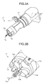
- FIGs. 3A and 3B are schematic perspective views illustrating the configuration of the hand 17. A distal end portion of the hand 17 illustrated in FIG. 3A is expanded and illustrated in FIG. 3B .
- the hand 17 mounted on the first arm section 11 includes a chuck portion 17a, projections 17b, and a gripper 17c.
- the chuck portion 17a includes three chuck jaws 17aa. Proximal end portions of the chuck jaws 17aa are respectively supported by discrete rotary portions 17ab.
- the rotary portion 17ab is formed to a substantially teardrop shape, and placed rotatably around a rotation axis parallel to an extension direction of the hand 17.
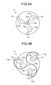
- FIGs. 4A and 4B are schematic front views for illustrating the chucking operation of the hand 17.
- FIG. 4A illustrates a state where the chuck jaws 17aa are closed.
- FIG. 4B illustrates a state where the chuck jaws 17aa are open.
- the state where the chuck jaws 17aa are closed indicates a state where the chuck jaws 17aa are gathered in the center of the distal end portion of the hand 17. Such a state corresponds to a state where the rotary portions 17ab are not being driven.
- the state where the chuck jaws 17aa are open indicates a state where each of the rotary portions 17ab is rotated and driven around a rotation axis Ra parallel to the extension direction of the hand 17, and accordingly the chuck jaws 17aa are opened outward of the hand 17 while each of the chuck jaws 17aa takes an arc path.
- FIG. 4B illustrate a state where the chuck jaws 17aa are opened to the maximum until coming into contact with the projections 17b.
- the rotary portions 17ab are rotated and driven in the reverse direction to when opened and accordingly the chuck jaws 17aa are closed toward the center of the distal end portion of the hand 17 while taking the same arc paths.
- the opening and closing mechanism of the chuck jaws 17aa is configured in this manner, using the rotary portions 17ab that rotate around their respective rotation axes Ra parallel to the extension direction of the hand 17. Accordingly, it is possible to obtain an effect that the dimension width of the hand 17 is reduced, and the hand 17 can be made thinner. This point is advantageous, for example, when a ring-shaped member is chucked from an inner periphery side (which is described below).
- the rotary portions 17ab are formed to a substantially teardrop shape, and their thin distal end portions are placed in such a manner as to abut one another. Accordingly, it is also possible to obtain an effect that the rotary portions 17ab can rotate without interfering with one another.
- the rotation amount of the rotary portions 17ab is controlled at the operation instruction of the controller 20. Accordingly, the opening/closing amount of the chuck jaws 17aa is made variable. Consequently, a variety of kinds of chucking target objects having different dimensions and the like (that is, the work W, the first part, and the like) can be handled.
- the hand 17 can open the chuck jaws 17aa outward from the center of the distal end portion of the hand 17. Accordingly, when the chucking target object has a hollow shape such as a ring, the chuck jaws 17aa are pressed against the inner periphery side of the chucking target object while being opened, and accordingly the hand 17 can chuck the chucking target object.
- the chucking target object can be chucked by being caught by the chuck jaws 17aa from the outer periphery side.
- the robot 10 can be operated according to the condition. Accordingly, the work W can be processed efficiently.
- a chucking method where the chucking direction is set to the outer periphery side may be described as “outer-periphery chuck,” and a chucking method where the chucking direction is set to the inner periphery side as “inner-periphery chuck.”
- the hand 17 further includes a swirl-stop portion 17d and a sensor portion 17e.
- the swirl-stop portion 17d is a member to prevent a chucking target object with a slippery inner periphery side from rotating by being brought into contact with an end of the chucking target object when the chucking target object is "inner-periphery chucked" by the chuck jaws 17aa.
- the swirl-stop portion 17d is preferred to be formed of a rubber material or the like.
- the sensor portion 17e is a detection device configured using a color sensor and the like, and is used for, for example, identification of a chucking target object chucked by the chuck jaws 17aa.
- the projections 17b and the gripper 17c which have been illustrated in FIG. 3A , are described in a series of operations of the robot 10 described below with reference to FIGs. 7A to 7H .
- FIG. 5 is a block diagram of the robot system 1 according to the embodiment. In FIG. 5 , only components necessary for the description of the robot system 1 are illustrated, and a description of general components is omitted.
- the controller 20 includes a control unit 21 and a storage unit 22.
- the control unit 21 further includes a work determination unit 21a, a chucking direction selection unit 21b, and an instruction unit 21c.
- a detection unit 5 illustrated outside the controller 20 is a block indicating the whole of the detection devices such as the above-mentioned camera unit 100 (see FIG. 1 ) and sensor portion 17e (see FIG. 3B ).
- the control unit 21 performs the overall control of the controller 20.
- the work determination unit 21a receives detection information containing the state of the work W detected by the detection unit 5, and the like, and determines the state of the work W based on the detection information.
- the state determination of the work W includes determination of the identification of the work W, which is made by matching the detection information and work identification information 22a.
- the work identification information 22a is information on the identification of the work W such as the shape and dimensions of the work W, and is preregistered in the storage unit 22.
- the state determination is also made for not only the work W but also the whole of chucking target objects to be chucked by the hand 17.
- the work determination unit 21a notifies the determination content to the chucking direction selection unit 21b.
- the chucking direction selection unit 21b selects the chucking direction of the chuck jaws 17aa based on the determination content notified by the work determination unit 21a, teaching information 22b, and the like. Moreover, the chucking direction selection unit 21b notifies the selected chucking direction to the instruction unit 21c.
- the instruction unit 21c generates operation signals that operate various devices such as the robot 10, and the hand 17 and the detection unit 5, which are included in the robot 10, based on the notified chucking direction and the teaching information 22b to output to various devices.
- the teaching information 22b is information containing teaching data for various devices of the robot system 1, and is preregistered via an input device (such as a programming pendant) whose illustration is omitted.
- the teaching data contains a form of the processing operation performed on the work W (specifically, information such as how and which members are assembled to the work W in what order).
- the storage unit 22 is a storage device such as a hard disk drive or a nonvolatile memory.
- the work identification information 22a and the teaching information 22b are stored in the storage unit 22.
- the contents of the work identification information 22a and the teaching information 22b have already been described. Therefore, their descriptions are omitted here.
- the components illustrated inside the controller 20 in FIG. 5 may not be placed only in the controller 20.
- an improvement in throughput may be promoted by storing any or all of the work identification information 22a and the teaching information 22b, which are stored in the storage unit 22, in an internal memory of the robot 10.
- FIG. 5 illustrates an example where the controller 20 determines the state of the work W based on the detection information from the detection unit 5, the preregistered work identification information 22a, and the like.
- necessary information may be sequentially obtained from a higher-level device connected to the controller 20 in such a manner as to be able to communicate with each other.
- FIG. 6A is a schematic plan view of the work W.
- FIG. 6B is a schematic plan view of the first part p1.
- FIG. 6C is a schematic plan view of the second part p2.
- FIG. 6D is a diagram illustrating the outline of the procedure for assembling the work W.
- the work W being a bracket is a member having a ring shape, and includes an inner peripheral portion Wi.
- the first part p1 being a bearing is a ring-shaped member, and includes an inner peripheral portion p1i and an outer peripheral portion p1o.
- the second part p2 being a retaining ring is a ring-shaped member, and includes an inner peripheral portion p2i and an outer peripheral portion p2o.
- the first part p1 is mounted in the inner peripheral portion Wi of the work W first (see arrows 601 in the figure).
- the second part p2 is mounted on an upper part of the mounted first part p1 (see arrows 602 in the figure).
- FIGs. 7A to 7H are explanatory views for illustrating the procedure for assembling the work W.
- the robot 10 takes out the work W from the stocker 41 of the transport pallet 40 and transports the work W (see an arrow 701 in the figure).
- the work W is placed on the workbench 50 with a guiding jig 54 provided on the workbench 50 as the center (see an arrow 702 in the figure).
- the guiding jig 54 is a jig for guiding the first part p1.
- the robot 10 takes out the first part p1 from the first part supply unit 60 and transports the first part p1 (see an arrow 703 in the figure).
- outer-periphery chuck here is that it is necessary to guide the inner peripheral portion p1i of the first part p1 in contact with a peripheral edge of the guiding jig 54.
- the robot 10 then mounts the first part p1 in the inner peripheral portion Wi of the work W while guiding the first part p1 with the guiding jig 54 (see an arrow 704 in the figure).
- the robot 10 places the jig J1 on the work W (see an arrow 705 in the figure).
- the inner peripheral portion J1i of the jig J1 is formed to a taper shape that gradually reduces in diameter toward a lower side.
- the robot 10 takes out the second part p2 from the second part supply unit 70 and transports the second part p2 (see an arrow 706 in the figure).
- inner-periphery chuck here is to temporarily place the outer peripheral portion p2o (see FIG. 6C ) of the second part p2 in contact with the inner peripheral portion J1i of the jig J1 (see an arrow 707 of FIG. 7D ).
- the robot 10 closes the chuck portion 17a of the hand 17, puts the chuck portion 17a in a hollow portion inside the inner peripheral portion J2i of the jig J2, and brings the projections 17b of the hand 17 into contact with an end of the jig J2.
- the jig J2 is then pressed from a direction indicated by an arrow 709 in the figure to press the second part p2 onto the upper part of the first part p1 mounted in the work W.
- the robot 10 transports the work W to the adhesive application unit 90 while holding the work W with the gripper 17c of the hand 17, and applies an adhesive to the mounting locations of the first part p1 and the second part p2.
- the work W is subsequently transported to the imaging area of the camera unit 100 to inspect the adhesive application state with imaging data.
- the work W is then transported to and stored on the dry shelving 80 (see arrows 710 in the figure).
- the reason why the gripper 17c is used in the procedure is to reduce the risk of the chuck portion 17a being contaminated by the adhesive.
- the robot 10 performs an operation of sliding and drawing a dry pallet 82 being a shelf of the dry shelving 80 (see an arrow 712 in the figure), or an operation of storing the dry pallet 82 (see an arrow 711 in the figure).
- the robot 10 chucks the handle portion 81 attached to the dry pallet 82 with the chuck portion 17a of the hand 17, and accordingly these operations can be performed.
- the hand 17 is required to "inner-periphery chuck" the hole portion 81a with the chuck jaws 17aa from the inside of the hole portion 81a (see three arrows in the figure).
- the work W that stored on the dry shelving 80 in FIG. 7G and finished being dried for a predetermined time is transported by the hand 17 and stored in the stocker 41.
- the procedure for assembling one work W then ends.
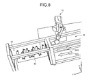
- the above-mentioned handle portion 42 (see FIG. 1 ) and handle portion 43 (see FIG. 1 ) are formed to a similar shape to that of the handle portion 81 illustrated in FIG. 7H . Accordingly, the robot 10 can perform the operation of sliding the transport pallet 40 (see FIG. 1 ). Such a case is illustrated in FIG. 8 .
- FIG. 8 is a schematic perspective view illustrating the operation of sliding the transport pallet 40 by the robot 10.
- the robot 10 performs an operation of chucking the handle portion 42 (illustration omitted) or the handle portion 43 (illustration omitted) with the chuck jaws 17aa and pulling the hand 17.
- the transport pallet 40 can be slid from the worker side area 32 to the robot side area 31 (see an arrow 801 in the figure).
- the transport pallet 40 can be slid from the robot side area 31 to the worker side area 32 by performing a pushing operation with the hand 17 (see an arrow 802 in the figure).
- the robot system 1 can cause the robot 10 to perform all the steps of processing of the work W from the carrying in of the work W into the cell 2 to carrying out without replacing the hand 17.
- the work W can be processed efficiently.
- various chucking target objects including the work W can be chucked and transported only with the hand 17 of the robot 10. Accordingly, there is no need to provide a drive mechanism dedicated for transport or the like. In other words, it can contribute to the avoidance of an increase in the size of the system.
- FIG. 8 illustrates the case where the transport pallet 40 includes one tier, but the transport pallet 40 may include multiple tiers along the z axis.
- the guide rail 33 that circulates across the two upper and lower tiers inside the work supply unit 3 (see FIG. 1 ) may be placed to slide the transport pallet 40 along the guide rail 33.
- the transport pallet 40 is configured in a circulatable manner. Accordingly, the work W can be carried in and out without backing up, and therefore the efficiency can be further promoted.
- the robot system includes the robot, the determination unit (work determination unit), the selection unit (chucking direction selection unit), and the instruction unit.
- the robot includes the robot hand (hand) having three or more chuck jaws.
- the determination unit obtains information on a member formed including a substantially ring shape and determines the state of the member.
- the selection unit selects whether to hold the member with the chuck jaws from the inner peripheral side or outer peripheral side based on the determination result of the determination unit.
- the instruction unit transports the member while holding the member with the chuck jaws based on the selection result of the selection unit, and instructs the robot to perform the operation of assembling a predetermined processed product using the member.
- the robot system according to the embodiment can process a work efficiently without increasing the size of the system.
- the number of chuck jaws is three.
- the number of chuck jaws is not limited and is required to be at least three or more.
- the chuck jaws are rotated by the rotation mechanism to be opened and closed.
- the chuck jaws may be opened and closed by, not limited to the rotation mechanism, but, for example, being linearly moved by a linear motion mechanism.
- the units constructed as separate bodies in the above-mentioned embodiment may be constructed as one unit.
- the first and second part supply units may be constructed as one intermediate member supply unit.
- the above-mentioned embodiment has illustrated a single-arm robot, but is not limited to this.
- a multiple arm robot including two or more arms may be used.
- the above-mentioned embodiment has illustrated a multi-axis robot having seven axes. However, the number of axes is not limited.
Landscapes
- Engineering & Computer Science (AREA)
- Robotics (AREA)
- Mechanical Engineering (AREA)
- Health & Medical Sciences (AREA)
- General Health & Medical Sciences (AREA)
- Orthopedic Medicine & Surgery (AREA)
- Automation & Control Theory (AREA)
- Manipulator (AREA)
- Automatic Assembly (AREA)
Applications Claiming Priority (1)
| Application Number | Priority Date | Filing Date | Title |
|---|---|---|---|
| PCT/JP2012/060597 WO2013157119A1 (fr) | 2012-04-19 | 2012-04-19 | Système de robot |
Publications (1)
| Publication Number | Publication Date |
|---|---|
| EP2839935A1 true EP2839935A1 (fr) | 2015-02-25 |
Family
ID=49383101
Family Applications (1)
| Application Number | Title | Priority Date | Filing Date |
|---|---|---|---|
| EP12874699.7A Withdrawn EP2839935A1 (fr) | 2012-04-19 | 2012-04-19 | Système de robot |
Country Status (5)
| Country | Link |
|---|---|
| US (1) | US20150019003A1 (fr) |
| EP (1) | EP2839935A1 (fr) |
| JP (1) | JPWO2013157119A1 (fr) |
| CN (1) | CN104203504B (fr) |
| WO (1) | WO2013157119A1 (fr) |
Cited By (1)
| Publication number | Priority date | Publication date | Assignee | Title |
|---|---|---|---|---|
| EP4582227A4 (fr) * | 2022-09-02 | 2025-12-24 | Daikin Ind Ltd | Système de robot, système de pressage automatisé, programme et gabarit de pressage |
Families Citing this family (8)
| Publication number | Priority date | Publication date | Assignee | Title |
|---|---|---|---|---|
| US10857674B2 (en) * | 2015-04-28 | 2020-12-08 | Seiko Epson Corporation | Robot system and robot |
| JP6577233B2 (ja) * | 2015-05-11 | 2019-09-18 | 株式会社安川電機 | 生命工学・医薬品化学用自動作業セル、生命工学・医薬品化学用自動作業方法、及び自動作業セル |
| US20180281203A1 (en) * | 2017-03-31 | 2018-10-04 | Sumitomo Chemical Company, Limited | Robot arm and transfer system |
| US10634625B2 (en) * | 2017-03-31 | 2020-04-28 | Sumitomo Chemical Company, Limited | Transfer system and transfer method |
| JP2019063909A (ja) * | 2017-09-29 | 2019-04-25 | ファナック株式会社 | ロボット |
| JP7219148B2 (ja) * | 2018-04-25 | 2023-02-07 | 住友化学株式会社 | 検査システム及び検査システムの駆動方法 |
| US11633861B2 (en) * | 2019-03-01 | 2023-04-25 | Commscope Technologies Llc | Systems, methods and associated components for robotic manipulation of physical objects |
| CN113401853B (zh) * | 2021-06-23 | 2023-03-24 | 中国核动力研究设计院 | 一种用于干燥盐桶的开盖和封盖装置 |
Family Cites Families (22)
| Publication number | Priority date | Publication date | Assignee | Title |
|---|---|---|---|---|
| JPS5928487U (ja) * | 1982-08-12 | 1984-02-22 | 日本電産コパル株式会社 | ロボツトハンドの物品把持装置 |
| JPS5973286A (ja) * | 1982-10-16 | 1984-04-25 | 株式会社日平トヤマ | 搬送方法およびその装置 |
| JPS60161533U (ja) * | 1984-04-04 | 1985-10-26 | 日立精機株式会社 | フイ−ダの割出し装置 |
| US4598942A (en) * | 1984-07-23 | 1986-07-08 | Westinghouse Electric Corp. | Force-controlled gripper with adaptive accommodation |
| JPS61169595U (fr) * | 1985-04-09 | 1986-10-21 | ||
| JPH0451327U (fr) * | 1990-09-03 | 1992-04-30 | ||
| JPH04133587U (ja) * | 1991-05-31 | 1992-12-11 | ぺんてる株式会社 | ユニバ−サル把持装置 |
| JP2002292589A (ja) * | 2001-03-30 | 2002-10-08 | Shindengen Electric Mfg Co Ltd | フランジ付き筒体のチャック装置 |
| JP4390172B2 (ja) * | 2001-05-09 | 2009-12-24 | 本田技研工業株式会社 | 治工具ストッカと作業用ロボットのシステム |
| JP2003062784A (ja) * | 2001-08-27 | 2003-03-05 | Shindengen Electric Mfg Co Ltd | フランジ付き筒体のチャック装置 |
| JP2003191193A (ja) * | 2001-12-21 | 2003-07-08 | Ricoh Co Ltd | スライド式チャック及びその把持方法、並びに記録媒体 |
| JP4006580B2 (ja) | 2002-05-01 | 2007-11-14 | 株式会社富士通ゼネラル | モータの組立装置 |
| JP4257570B2 (ja) * | 2002-07-17 | 2009-04-22 | 株式会社安川電機 | 搬送用ロボットのティーチング装置および搬送用ロボットのティーチング方法 |
| JP3876260B2 (ja) * | 2004-09-16 | 2007-01-31 | ファナック株式会社 | 物品供給装置 |
| JP4182074B2 (ja) * | 2005-03-03 | 2008-11-19 | ファナック株式会社 | ハンド及びハンドリングロボット |
| JP2007223002A (ja) * | 2006-02-24 | 2007-09-06 | Honda Motor Co Ltd | 作業装置及びロボットによる作業方法 |
| JP2008036716A (ja) * | 2006-08-01 | 2008-02-21 | Komatsu Machinery Corp | ワーク把持装置 |
| JP2009291871A (ja) * | 2008-06-04 | 2009-12-17 | Mitsubishi Electric Corp | ロボット用把持ハンド |
| JP5306948B2 (ja) * | 2009-09-10 | 2013-10-02 | 本田技研工業株式会社 | マニプレータ装置 |
| JP2011156649A (ja) * | 2010-02-04 | 2011-08-18 | Yaskawa Electric Corp | グリッパ装置およびそのストローク量変更方法 |
| JP5229253B2 (ja) * | 2010-03-11 | 2013-07-03 | 株式会社安川電機 | ロボットシステム及びロボット装置並びにワーク取り出し方法 |
| JP2012066321A (ja) * | 2010-09-22 | 2012-04-05 | Fuji Electric Co Ltd | ロボットシステムおよびロボット組立システム |
-
2012
- 2012-04-19 JP JP2014511042A patent/JPWO2013157119A1/ja active Pending
- 2012-04-19 CN CN201280071832.1A patent/CN104203504B/zh not_active Expired - Fee Related
- 2012-04-19 WO PCT/JP2012/060597 patent/WO2013157119A1/fr not_active Ceased
- 2012-04-19 EP EP12874699.7A patent/EP2839935A1/fr not_active Withdrawn
-
2014
- 2014-10-03 US US14/505,499 patent/US20150019003A1/en not_active Abandoned
Non-Patent Citations (1)
| Title |
|---|
| See references of WO2013157119A1 * |
Cited By (1)
| Publication number | Priority date | Publication date | Assignee | Title |
|---|---|---|---|---|
| EP4582227A4 (fr) * | 2022-09-02 | 2025-12-24 | Daikin Ind Ltd | Système de robot, système de pressage automatisé, programme et gabarit de pressage |
Also Published As
| Publication number | Publication date |
|---|---|
| CN104203504A (zh) | 2014-12-10 |
| WO2013157119A1 (fr) | 2013-10-24 |
| US20150019003A1 (en) | 2015-01-15 |
| JPWO2013157119A1 (ja) | 2015-12-21 |
| CN104203504B (zh) | 2016-03-09 |
Similar Documents
| Publication | Publication Date | Title |
|---|---|---|
| EP2839935A1 (fr) | Système de robot | |
| TWI657903B (zh) | Manufacturing system, manufacturing system construction method, end effector, robot, and robot operation method | |
| US8788089B2 (en) | Unloading system | |
| EP2623269A2 (fr) | Équipement d'assemblage et procédé d'assemblage | |
| JP6252597B2 (ja) | ロボットシステム | |
| US11623355B2 (en) | Method for producing a robot and device for carrying out said method | |
| US20160114444A1 (en) | Method for making tools and/or handling equipment available, and associated devices | |
| JP5910725B2 (ja) | ロボットシステム | |
| KR20200096326A (ko) | 융통성 있는 조립 기계, 시스템 및 방법 | |
| CN102152298A (zh) | 机器人系统及工件取出方法 | |
| JP6892018B2 (ja) | ロボット装置 | |
| JP2010105105A (ja) | 自動生産装置 | |
| JP2020536761A5 (fr) | ||
| JP6420533B2 (ja) | 作業装置 | |
| KR20160049418A (ko) | 로봇 시스템을 구비한 씨엔씨 공작기계 | |
| KR20180101149A (ko) | 트랜스퍼 유닛 및 이를 이용한 공정 장치 | |
| JP5999198B2 (ja) | ロボットシステム | |
| CN103072130B (zh) | 机器人系统和制造工件的方法 | |
| US20180338397A1 (en) | Method and devices for picking and placing workpieces into devices under manufacture using dual robots | |
| JP6366665B2 (ja) | ロボット装置、組立装置、把持ハンド、および物品の製造方法 | |
| KR20150133493A (ko) | 공작기계용 공작물 인식 장치 | |
| JP2007185746A (ja) | 部品把持機構 | |
| CN111453284B (zh) | 加工品的自动三维测定检查系统 | |
| CN111203743B (zh) | 利用夹具的机器人桌台跟踪进行的连续加工 | |
| WO2026004177A1 (fr) | Système de transport et robot |
Legal Events
| Date | Code | Title | Description |
|---|---|---|---|
| PUAI | Public reference made under article 153(3) epc to a published international application that has entered the european phase |
Free format text: ORIGINAL CODE: 0009012 |
|
| 17P | Request for examination filed |
Effective date: 20141016 |
|
| AK | Designated contracting states |
Kind code of ref document: A1 Designated state(s): AL AT BE BG CH CY CZ DE DK EE ES FI FR GB GR HR HU IE IS IT LI LT LU LV MC MK MT NL NO PL PT RO RS SE SI SK SM TR |
|
| AX | Request for extension of the european patent |
Extension state: BA ME |
|
| STAA | Information on the status of an ep patent application or granted ep patent |
Free format text: STATUS: THE APPLICATION HAS BEEN WITHDRAWN |
|
| 18W | Application withdrawn |
Effective date: 20150601 |