EP2840577B1 - Dispositif de commande centrale pour centrale nucléaire - Google Patents
Dispositif de commande centrale pour centrale nucléaire Download PDFInfo
- Publication number
- EP2840577B1 EP2840577B1 EP13767260.6A EP13767260A EP2840577B1 EP 2840577 B1 EP2840577 B1 EP 2840577B1 EP 13767260 A EP13767260 A EP 13767260A EP 2840577 B1 EP2840577 B1 EP 2840577B1
- Authority
- EP
- European Patent Office
- Prior art keywords
- plant
- operating state
- unit
- nuclear power
- power plant
- Prior art date
- Legal status (The legal status is an assumption and is not a legal conclusion. Google has not performed a legal analysis and makes no representation as to the accuracy of the status listed.)
- Active
Links
Images


Classifications
-
- G—PHYSICS
- G21—NUCLEAR PHYSICS; NUCLEAR ENGINEERING
- G21D—NUCLEAR POWER PLANT
- G21D3/00—Control of nuclear power plant
- G21D3/001—Computer implemented control
-
- G—PHYSICS
- G21—NUCLEAR PHYSICS; NUCLEAR ENGINEERING
- G21D—NUCLEAR POWER PLANT
- G21D3/00—Control of nuclear power plant
- G21D3/008—Man-machine interface, e.g. control room layout
-
- Y—GENERAL TAGGING OF NEW TECHNOLOGICAL DEVELOPMENTS; GENERAL TAGGING OF CROSS-SECTIONAL TECHNOLOGIES SPANNING OVER SEVERAL SECTIONS OF THE IPC; TECHNICAL SUBJECTS COVERED BY FORMER USPC CROSS-REFERENCE ART COLLECTIONS [XRACs] AND DIGESTS
- Y02—TECHNOLOGIES OR APPLICATIONS FOR MITIGATION OR ADAPTATION AGAINST CLIMATE CHANGE
- Y02E—REDUCTION OF GREENHOUSE GAS [GHG] EMISSIONS, RELATED TO ENERGY GENERATION, TRANSMISSION OR DISTRIBUTION
- Y02E30/00—Energy generation of nuclear origin
- Y02E30/30—Nuclear fission reactors
Definitions
- the present invention relates to a central control device for a nuclear power plant.
- An object of the present invention in relation to the issue (1) is to provide a central control device of a nuclear power plant which can reduce a load of an operator and which can improve the safety and reliability of the nuclear power plant.
- Another object of the present invention in relation to the issue (2) is to provide a plant operation support device and a plant operation support method which can correctly and promptly predict the operating state of the plant.
- the invention consists in a central control device for a nuclear power plant according to claim 1.
- a plant operation support device including: a virtual plant creation unit for acquiring operating state data on an actual plant and creating a virtual plant in conformity to an operating state of the actual plant; a reference data storage unit for storing in advance reference data on the virtual plant assuming various operating states of the actual plant; an operating state monitoring unit for monitoring the operating state of the actual plant and sending the operating state data on the actual plant to the virtual plant creation unit, while acquiring from the reference data storage unit the reference data corresponding to change, if occurs, in the operating state of the actual plant and sending the reference data to the virtual plant creation unit; an operating state prediction unit for creating a predicted virtual plant in which an operating state after a lapse of arbitrary time is predicted by accelerating the operating state of the virtual plant created by the virtual plant creation unit at an arbitrary speed; and an operating state displaying unit for displaying the operating state of the actual plant and the operating state of the predicted virtual plant.
- a plant operation support method including: a virtual plant creation step of acquiring operating state data on an actual plant and creating a virtual plant in conformity to an operating state of the actual plant; an operating state monitoring step of monitoring the operating state of the actual plant and providing the operating state data on the actual plant to the virtual plant creation step, while providing reference data created in advance to correspond to change, if occurs, in the operating state of the actual plant to the virtual plant creation step; an operating state prediction step of creating a predicted virtual plant in which an operating state after a lapse of arbitrary time is predicted by accelerating the operating state of the virtual plant created in the virtual plant creation step at an arbitrary speed; and an operating state display step of displaying the operating state of the actual plant and the operating state of the predicted virtual plant.
- an operation procedure document corresponding to an input operation to a monitoring operation device is displayed on the monitoring operation device.
- FIG. 1 is a configuration view illustrating a nuclear power plant according to a first embodiment of the present invention.
- FIG. 1 illustrates the nuclear power plant including a pressurized water reactor (PWR) in one example.
- PWR pressurized water reactor
- BWR boiling water reactor
- a nuclear power plant 110 of FIG. 1 includes a nuclear reactor 112, a steam generator 113, a pressurizer 116, and a cooling water pump 117 in a containment 111.
- An outlet side of the nuclear reactor 112 and an inlet side of the steam generator 113 are connected to each other via a first cooling water pipe 114, and the pressurizer 116 is placed on the cooling water pipe 114.
- An outlet side of the steam generator 113 and an inlet side of the nuclear reactor 112 are connected to each other via a second cooling water pipe 115, and a cooling water pump 117 is placed on the second cooling water pipe 115.
- the nuclear power plant 110 also includes a steam turbine 118, a condenser 119, and a generator 123.
- the steam turbine 118 is coupled to the generator 123 via a turbine rotor.
- An inlet portion of the steam turbine 118 is connected to an outlet portion of the steam generator 113 via a third cooling water pipe 120, while an outlet portion of the steam turbine 118 is connected to the condenser 119.
- the condenser 119 is connected to an inlet portion of the steam generator 113 via a fourth cooling water pipe 121.
- a condensate pump 122 is placed on the fourth cooling water pipe 121.
- the nuclear reactor 112 uses slightly enriched uranium or mixed oxide (MOX) as a fuel, and also uses light water as primary cooling water and a neutron moderator.
- the nuclear reactor 112 heats the primary cooling water with the fuel to generate high-temperature and high-pressure water.
- the pressurizer 116 maintains the primary cooling water in a high pressure state of 150 to 160 atmospheric pressure. As a consequence, there is generated high-temperature and high-pressure primary cooling water which is not boiled throughout the entire reactor core.
- This high-temperature and high-pressure primary cooling water is supplied to the steam generator 113 via the first cooling water pipe 114.
- the steam generator 113 performs heat exchange between the primary cooling water from the nuclear reactor 112 and the secondary cooling water to generate secondary cooling water steam.
- the steam (secondary cooling water) is supplied to the steam turbine 118 via the third cooling water pipe 120.
- the cooling water pump 117 returns the heat-exchanged primary cooling water to the nuclear reactor 112 via the second cooling water pipe 115.
- the steam turbine 118 generates driving torque with the thermal energy of the secondary cooling water coming from the steam generator 113, and drives the generator 123 via a rotor.
- the condenser 119 performs heat exchange between the secondary cooling water which passed the steam turbine 118 and a refrigerant to condense steam.
- the condenser 119 pumps up and takes in sea water used as a refrigerant from an intake pipe, and discharges the heat-exchanged refrigerant through a drain pipe.
- the condensate pump 122 returns the heat-exchanged secondary cooling water to the steam generator 113 via the fourth cooling water pipe 121.
- the generator 123 is continuously driven by circulating the secondary cooling water along the steam generator 113, the steam turbine 118, and the condenser 119.
- the nuclear power plant 110 also includes a control protection system facility 130 and a central control device 140.
- the control protection system facility 130 which is a general purpose computer or a dedicated purpose computer, includes a rack of reactor control system measuring instruments (illustration omitted) having a central processing unit (CPU), a read only memory (ROM), a random access memory (RAM), and the like.
- This control protection system facility 130 controls the operation of various devices, such as pumps and valves for operating the nuclear power plant 110, on the basis of signals from various sensors (illustration omitted) which acquire state quantity of the nuclear power plant 110.
- the control protection system facility 130 also processes the signals from various sensors of the nuclear power plant 110, and outputs specified signals (for example, digital signals indicating process parameters, such as a water level, a pressure, and a flow rate of the nuclear reactor 112, signals indicating the state of respective systems and state of respective devices, alarm signals when abnormality occur, etc.) to the central control device 140.
- the control protection system facility 130 controls various devices of the nuclear power plant 110 on the basis of the signals from the central control device 140.
- the nuclear power plant 110 is controlled so as to implement functions such as stopping nuclear reaction in the nuclear reactor 112, cooling the nuclear power plant 110, and preventing leakage of radioactive substances from the nuclear power plant 110.
- the central control device 140 is composed of a central control panel for monitoring and controlling the nuclear power plant 110, and is placed in a central control room of the nuclear power plant 110.
- the central control device 140 displays specified information relating to the status of the nuclear power plant 110 such as an operating status and a safety status (for example, process parameters, such as the water level, the pressure, and the flow rate of the nuclear reactor 112, the state of respective systems, the state of respective devices, etc.) on a display unit on the basis of the signals from the control protection system facility 130.
- process parameters such as the water level, the pressure, and the flow rate of the nuclear reactor 112, the state of respective systems, the state of respective devices, etc.
- the central control device 140 outputs signals for controlling the respective systems and respective devices of the nuclear power plant 110 to the control protection system facility 130.
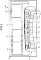
- FIG. 2 is an external configuration view illustrating one example of the central control device described in FIG. 1 .
- FIG. 2 illustrates the central control device having a central control panel.
- the central control device 140 is a central control device including an operation console 141 and a large-size indicator panel 142 (see FIG. 2 ).
- the operation console 141 which is a device for performing monitoring operation of the nuclear power plant 110, includes an alarm visual display unit (VDU) 411, a common system VDU 412, a safety system VDU 413, an operation procedure document VDU 414, and a hardware operation device 415.
- the alarm VDU 411 is a monitoring operation device having both a function as a display unit that displays various kinds of alarms relating to the nuclear power plant 110 when abnormality occurs and a function as an operation unit that operates the nuclear power plant 110.
- the common system VDU 412 is a monitoring operation device having both a function as a display unit that displays information on the nuclear power plant 110 and a function as an operation unit that operates the nuclear power plant 110.
- the safety system VDU 413 is a monitoring operation device having both a function as a display unit that displays information on a safety system of the nuclear power plant 110 and a function as an operation unit that operates the safety system of the nuclear power plant 110.
- the operation procedure document VDU 414 is a monitoring operation device having a function to display operation procedure documents, a function as a display unit that displays the information on the nuclear power plant 110, and a function as an operation unit that operates the nuclear power plant 110.
- the alarm VDU 411, the common system VDU 412, the safety system VDU 413, and the operation procedure document VDU 414 are each composed of, for example, a touch panel operation device.
- the hardware operation device 415 is composed of various kinds of physical switches for operating the nuclear power plant 110.
- the large-size indicator panel 142 includes fixed display units 421 and a variable display unit 422.
- the fixed display units 421 display key parameters, typical alarms, and the like on the constant basis.
- the fixed display units 421 are composed of, for example, an OK monitor that displays specified information such as the operating status and the safety status of the nuclear power plant 110, and a bypassed and inoperable state indication (BISI) monitor that displays whether or not various devices such as pumps and valves for operating the nuclear power plant 110 are operational.
- the variable display unit 422 can selectively display the display screens of the respective VDUs 411 to 414 of the operation console 141.
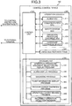
- FIG. 3 is a functional block diagram illustrating the central control device described in FIG. 1 .
- the central control device 140 adopts the following configuration.
- the central control device 140 includes a control unit 143 and a storage unit 144 (see FIG. 3 ).
- the control unit 143 is, for example, a central processing unit (CPU) which reads and executes various kinds of programs and data stored in the storage unit 144 to perform comprehensive control on the operation of the central control device 140 and to implement various functions. Specifically, the control unit 143 performs display control of the operation console 141 and display control of the large-size indicator panel 142 on the basis of input signals from the control protection system facility 130 and the operation console 141. The control unit 143 also generates signals for controlling various devices of the nuclear power plant 110 on the basis of input signals from the operation console 141, and outputs the generated signals to the control protection system facility 130.
- CPU central processing unit
- the storage unit 144 which is a nonvolatile memory or a magnetic storage device for example, stores various kinds of programs and data used for processing performed in the control unit 143. Specifically, the storage unit 144 stores an operation procedure document selection and display program 441, an alarm display program 442, a diagnosis program 443, a plant information display program 444, a secular change diagnosis program 445, an operation history record program 446, and an incorrect operation detection program 447.
- the operation procedure document selection and display program 441 is a program that selects an operation procedure document corresponding to an input operation to one of the monitoring operation devices (the alarm VDU 411, the common system VDU 412, and the safety system VDU 413) of the operation console 141 and displays the operation procedure documents on the pertinent monitoring operation device.
- the alarm display program 442 is a program that displays corresponding alarms on the pertinent monitoring operation device and the large-size indicator panel 142 on the basis of specified alarm signals.
- the diagnosis program 443 is a program that diagnoses the status of the nuclear power plant 110 and displays the diagnosis result on the pertinent monitoring operation device.
- the plant information display program 444 is a program that displays an operation procedure document and information on the nuclear power plant 110 prescribed in the operation procedure document in association with each other on the pertinent monitoring operation device.
- the secular change diagnosis program 445 is a program that diagnoses change in state quantity of the nuclear power plant 110 during steady operation and displays the diagnosis result on the pertinent monitoring operation device.
- the operation history record program 446 is a program that records the corresponding operation prescribed in the operation procedure document displayed on the pertinent monitoring operation device and the input operation to the monitoring operation device in association with each other.
- the incorrect operation detection program 447 is a program that detects inconsistency between the corresponding operation prescribed in the operation procedure document displayed on the pertinent monitoring operation device and the input operation to the monitoring operation device.
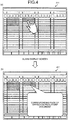
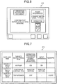
- FIGS. 4 to 7 are explanatory views illustrating the functions of the central control device described in FIG. 1 . These drawings illustrate the operation support performed with use of the operation procedure documents.
- the alarm VDU 411, the common system VDU 412, and the safety system VDU 413 on the operation console 141 are each composed of a touch panel operation device, which has both the function as a display unit and the function as an operation unit (see FIGS. 2 and 3 ).
- the alarm VDU 411 displays various kinds of alarms when abnormality occurs
- the common system VDU 412 displays various kinds of information pieces of the nuclear power plant 110
- the safety system VDU 413 displays various kinds of information pieces relating to the safety system of the nuclear power plant 110.
- the operator monitors the nuclear power plant 110 with use of these displays, and performs an input operation to one of the monitoring operation devices (the alarm VDU 411, the common system VDU 412, and the safety system VDU 413) as necessary.
- the control unit 143 selects an operation procedure document corresponding to the input operation, and pop-up displays the operation procedure document on the monitoring operation device to which the input operation was made. This makes it possible to reduce the load of the operator who has to select a necessary operation procedure document from huge operation procedure documents.
- the operation procedure documents include descriptions about operation procedures of the nuclear power plant 110 (for example, activation procedures, shutdown procedures, etc.), corresponding operations when abnormality occurs, a determination logic of the OK monitor, a diagnostic logic of the later-described diagnosis system, and the like.
- the above-stated execution history of the corresponding operation is managed in the external terminal 150 (see FIG. 1 ).
- the central control device 140 of the nuclear power plant 110 monitors and controls the nuclear power plant 110 (see FIG. 1 ).
- the central control device 140 also includes monitoring operation devices (for example, the alarm VDU 411, the common system VDU 412, and the safety system VDU 413 of the operation console 141) each having both a function as a display unit that displays information on the nuclear power plant 110 (for example, operation information, safety information, etc.) and a function as an operation unit that operates the nuclear power plant 110, and the control unit 143 that controls these monitoring operation devices (see FIG. 3 ).
- the control unit 143 also selects an operation procedure document corresponding to an input operation to a monitoring operation device, and displays the operation procedure document on the monitoring operation device (see FIGS. 4 and 5 ).
- an operation procedure document corresponding to an input operation to a monitoring operation device is displayed on the monitoring operation device, so that the load of the operator, who has to select a necessary operation procedure document from a large amount of operation procedure documents, can advantageously be reduced. Since the information from indicators, operation devices, alarms and the like is combined so that information contents suitable for the operation of the moment is presented to the pertinent monitoring operation device, the operator can perform corresponding operation while referring to this information and the operation procedure document. This provides an advantage that operation quality is improved even when the operator is unskilled and thereby the safety and reliability of the nuclear power plant 110 are improved.
- the control unit 143 displays on the pertinent monitoring operation device an alarm when abnormality occurs in the nuclear power plant 110 (see FIG. 4 ).
- the control unit 143 selects a corresponding operation procedure document, and displays the document on the monitoring operation device.
- the control unit 143 diagnoses the status of the nuclear power plant 110, and displays the diagnosis result on the pertinent monitoring operation device (see FIG. 5 ).
- the control unit 143 selects a corresponding operation procedure document, and displays the document on the monitoring operation device.
- the control unit 143 displays an operation procedure document and information on the nuclear power plant 110 prescribed in the operation procedure document in association with each other on the pertinent monitoring operation device (see FIG. 6 ).
- Such configuration provides an advantage that the operator can confirm necessary information while referring to the operation procedure document, so that the operation quality is advantageously improved and thereby the safety and reliability of the nuclear power plant 110 are improved.
- the control unit 143 displays the operation procedure document and the operation machine to be operated, which provides an advantage of being able to efficiently support the operator in his/her operation.
- the control unit 143 collects and displays the information necessary for the measure on the pertinent monitoring operation device, which provides an advantage of being able to efficiently support the operator in his/her operation.
- the control unit 143 also diagnoses transition in the state quantity of the nuclear power plant 110, and displays the diagnosis result on the pertinent monitoring operation device (illustration omitted).
- the control unit 143 selects a corresponding operation procedure document, and displays the document on the monitoring operation device.
- the control unit 143 records a corresponding operation prescribed in the operation procedure document displayed on the pertinent monitoring operation device and an input operation to the monitoring operation device in association with each other (see FIG. 7 ).
- an execution history of the corresponding operations by the operator can be recorded, which provides an advantage of being able to determine whether or not the corresponding operation is properly performed in conformity with the operation procedure document.
- control unit 143 also detects inconsistency between the corresponding operation prescribed in the operation procedure document displayed on the pertinent monitoring operation device and the input operation to the monitoring operation device (see FIG. 7 ). This provides an advantage of being able to determine incorrect operation and failure of performance with respect to the corresponding operation.
- FIG. 8 is a schematic configuration view of a plant with a plant operation support device according to another example.
- a plant operation support device 1 of this example is applied to, for example, a nuclear power plant (plant) 110.
- a pressurized water reactor 112 is applied to the nuclear power plant 110 for example.
- the pressurized water reactor 112 uses light water as a nuclear reactor coolant and a neutron moderator, the light water being high-temperature and high-pressure water which is not boiled throughout the entire primary system. This high-temperature and high-pressure water is sent to a steam generator to generate steam through heat exchange, and the generated steam is sent to a turbine generator to generate power.
- the pressurized water reactor 112 and a steam generator 113 are stored inside a containment 111.
- the pressurized water reactor 112 and the steam generator 113 are coupled via cooling water pipes 114 and 115.
- the cooling water pipe 114 is equipped with a pressurizer 116
- the cooling water pipe 115 is equipped with a cooling water pump 117.
- light water is used as a moderator and primary cooling water, and in order to suppress boiling of the primary cooling water in a reactor core unit, a primary cooling system is controlled to maintain high pressure state in the range of about 160 atmospheric pressure by the pressurizer 116.
- the pressurized water reactor 112 the light water as the primary cooling water is heated with slightly enriched uranium or MOX as a fuel, and high-temperature primary cooling water is sent to the steam generator 113 through the cooling water pipe 114 in the state of being maintained at a specified high pressure by the pressurizer 116.
- this steam generator 113 heat exchange is performed between the high-pressure and high-temperature primary cooling water and the secondary cooling water, and the cooled primary cooling water is returned to the pressurized water reactor 112 through the cooling water pipe 115.
- the steam generator 113 is coupled to a turbine 118 and a condenser 119, which are provided outside the containment 111, via the cooling water pipes 120 and 121.
- the cooling water pipe 121 is equipped with a condensate pump 122.
- the turbine 118 is connected to a generator 123, while the condenser 119 is coupled to an intake pipe 124 and a drain pipe 125 which supply and discharge the cooling water (for example, sea water). Therefore, the steam generated in the steam generator 113 through heat exchange with the high-pressure and high-temperature primary cooling water is sent to the turbine 118 through the cooling water pipe 120, and the turbine 118 is driven with the steam to generate power in the generator 123.
- the steam which has driven the turbine 118 is cooled in the condenser 119 and is then returned to the steam generator 113 through the cooling water pipe 121.
- the nuclear power plant 110 also includes a central control device 140.
- the central control device 140 which is a general purpose computer or a dedicated purpose computer, includes a CPU, a ROM, a RAM, and the like.
- the central control device 140 which is configured to monitor and control the nuclear power plant 110, controls the operation of various devices, such as valves and pumps for operating the nuclear power plant 110, on the basis of operating state data D1 from various sensors (illustration omitted) which acquire the state quantity of the nuclear power plant 110.
- the central control device 140 executes processing based on the operating state data D1 from various sensors of the nuclear power plant 110.
- the operating state data D1 includes, for example, parameter data indicating parameters, such as a water level, a pressure, and a flow rate of the nuclear reactor 112, device data indicating the state of respective systems and the state of respective devices, and alarm data when abnormality occurs.
- the central control device 140 controls various devices of the nuclear power plant 110 on the basis of the operating state data D1. As a result, the nuclear power plant 110 is controlled so that functions such as stopping nuclear reaction in the nuclear reactor 112, cooling the nuclear power plant 110, and preventing leakage of radioactive substances from the nuclear power plant 110, are implemented.
- FIG. 9 is a configuration view of the plant operation support device according to this example.
- the plant operation support device 1 has a plant operating state prediction function, a plant operating state diagnosis function, a plant operation procedure presentation function, and an operation confirmation function.
- the plant operating state prediction function includes operating state monitoring unit 11, virtual plant creation unit 12, operating state prediction unit 13, reference data storage unit 14, and operating state displaying unit 15.
- the operating state monitoring unit 11 is configured to monitor the operating state of the nuclear power plant 110.
- the nuclear power plant 110 is defined as an actual plant that is actually operated.
- the operating state monitoring unit 11 acquires and analyzes operating state data D1 on the actual plant 110.
- the virtual plant creation unit 12 creates a virtual plant 210 in conformity to the operating state of the actual plant 110.
- the virtual plant creation unit 12 is what is called a simulator, which acquires operating state data D1 on the actual plant 110 from the operating state monitoring unit 11 and simulates the actual plant 110.
- the virtual plant creation unit 12 reads the operating state data D1 on the actual plant 110 acquired by the operating state monitoring unit 11 with a given period and reflects the operating state data D1 upon the virtual plant 210. With this processing, the operating state of the actual plant 110 is conformed to the operating state (calculated value) of the virtual plant 210.
- the operating state data D1 includes alarm data
- the operating state monitoring unit 11 immediately acquires the operating state data D1
- the virtual plant creation unit 12 immediately reads the acquired operating state data D1.
- the operating state prediction unit 13 accelerates operating state calculation of the virtual plant 210, which was created by the virtual plant creation unit 12, at an arbitrary speed so as to calculate the operating state after a lapse of arbitrary time. As a result, a predicted virtual plant 210' in which the operating state after a lapse of arbitrary time is predicted is created.
- the reference data storage unit 14 is a data base storing in advance reference data D2 for creating the virtual plant 210 assuming various operating states of the actual plant 110.
- the various operating states of the actual plant 110 include, for example, a state of 100% rated operation, a start-up operating state, and a state immediately after automatic shutdown.
- the reference data D2 is the data created in advance in conformity to the operating states of the actual plant 110, so that the reference data D2 conforms to the actual operating state of the actual plant 110.
- the operating state monitoring unit 11 acquires reference data D2 corresponding to the operating state from the reference data storage unit 14, and sends the reference data D2 to the virtual plant creation unit 12.
- the virtual plant creation unit 12 creates a virtual plant 210 based on the sent reference data D2.
- the operating state displaying unit 15 is configured to display the operating state of the actual plant 110 and the operating state of a predicted virtual plant 210'.
- the operating state of the actual plant 110 is input from the operating state monitoring unit 11.
- the operating state of the predicted virtual plant 210' is input from the operating state prediction unit 13.
- the operating state of the actual plant 110 and the operating state of the predicted virtual plant 210' are displayed, for example, on an operating state display unit 16 in the large-size indicator panel 142 placed in the central control room (not illustrate) including the central control device 140.
- the operating state displaying unit 15 makes the operating state display unit 16 switch and display either the operating state of the actual plant 110 or the operating state of the predicted virtual plant 210', or display both the operating states in combination.
- FIG. 10 is a flow chart illustrating processing procedures of the plant operation support device according to this example.
- FIG. 10 illustrates the processing procedures of the plant operating state prediction function in the plant operation support device 1.
- the operating state data D1 on the actual plant 110 acquired by the operating state monitoring unit 11 is first sent to the virtual plant creation unit 12, where the virtual plant 210 is created (step S11).
- the operating state data D1 on the actual plant 110 acquired by the operating state monitoring unit 11 is sent to the virtual plant creation unit 12 with a given period.
- the operating state (calculated value) of the virtual plant 210 is synchronized with and is thereby conformed to the operating state data D1 on the actual plant 110 (step S12).
- step S13: Yes when the operating state data D1 (operating state) on the actual plant 110 acquired by the operating state monitoring unit 11 is changed from the previous data (step S13: Yes), the processing proceeds to step S14.
- step S13: No when the operating state data D1 on the actual plant 110 acquired by the operating state monitoring unit 11 is not changed from the previous data (step S13: No), the processing proceeds to step S16.
- step S14 it is determined whether or not to re-create the virtual plant 210 in the virtual plant creation unit 12.
- the operating state monitoring unit 11 reads reference data D2 from the reference data storage unit 14, and sends the reference data D2 to the virtual plant creation unit 12, where the virtual plant 210 is re-created (step S15).
- the actual plant 110 is not in an abnormal operation state, such as in the case where the operating state data D1 does not include alarm data, it is determined that the virtual plant 210 is not re-created (step S14: No), and the processing returns to step S12.
- step S16 operating state calculation is accelerated from the operating state of the latest virtual plant 210 at an arbitrary speed in the operating state prediction unit 13, so that a predicted virtual plant 210' is created in the virtual plant creation unit 12 (step S16).
- the operating state of the predicted virtual plant 210' is sent to the operating state prediction unit 13.
- the operating state of the actual plant 110 is acquired from the operating state monitoring unit 11 by the operating state displaying unit 15, while the operating state of the predicted virtual plant 210' is acquired from the operating state prediction unit 13. These operating states are displayed on the operating state display unit 16 (step S17).
- the plant operation support device 1 of this example includes: the virtual plant creation unit 12 for acquiring operating state data D1 on the actual plant 110 and creating a virtual plant 210 in conformity to the operating state of the actual plant 110; the reference data storage unit 14 for storing in advance reference data D2 on the virtual plant 210 assuming various operating states of the actual plant 110; the operating state monitoring unit 11 for monitoring the operating state of the actual plant 110 and sending the operating state data D1 on the actual plant 110 to the virtual plant creation unit 12, while acquiring reference data D2 corresponding to a change, if occurs, in the operating state of the actual plant 110 from the reference data storage unit 14 and sending the reference data D2 to the virtual plant creation unit 12; the operating state prediction unit 13 for creating a predicted virtual plant 210' in which an operating state after a lapse of arbitrary time is predicted by accelerating the operating state of the virtual plant 210 created by the virtual plant creation unit 12 at an arbitrary speed; and the operating state displaying unit 15 for displaying the operating state of the actual plant 110
- a plant operation support method of this example includes: a virtual plant creation step of acquiring operating state data D1 on the actual plant 110 and creating the virtual plant 210 in conformity to the operating state of the actual plant 110; an operating state monitoring step of monitoring the operating state of the actual plant 110 and sending the operating state data on the actual plant 110 to the virtual plant creation step, while providing the virtual plant creation step with reference data D2 created in advance to correspond to a change, if occurs, in the operating state of the actual plant 110; an operating state prediction step of creating a predicted virtual plant 210' in which an operating state after a lapse of arbitrary time is predicted by accelerating the operating state of the virtual plant 210 created in the virtual plant creation step at an arbitrary speed; and an operating state display step of displaying the operating state of the actual plant 110 and the operating state of the predicted virtual plant 210'.
- the operating state of the actual plant 110 and the operating state of the predicted virtual plant 210' are displayed on the operating state display unit 16, so that the operating state of the actual plant 110 after a lapse of arbitrary time can be compared with the current state.
- the operating state of the actual plant 110 suddenly changes, such as in the case where the operating state data D1 includes alarm data in particular, the virtual plant 210 and the predicted virtual plant 210' are immediately created with use of the reference data D2 conformed to the operating state of the actual plant 110, so that correct and rapid prediction can be achieved in response to the change in the operating state of the actual plant 110.
- the predicted virtual plant 210' can be created with use of the reference data D2 without waiting for the operating state data D1 to be read out if the operating state of the actual plant 110 is suddenly changed. This makes it possible to perform more rapid prediction. Moreover, after the predicted virtual plant 210' is created with use of the reference data D2, the operating state data D1 on the actual plant 110 is acquired and synchronized by interruption, so that more correct prediction can be performed.
- the plant operating state diagnosis function includes operating state diagnosis unit 21, diagnosis data storage unit 22, and diagnosis result displaying unit 23 as illustrated in FIG. 9 .
- the operating state diagnosis unit 21 diagnoses the operating state of the actual plant 110, while diagnosing the operating state of the predicted virtual plant 210'.
- the operating state data D1 on the actual plant 110 is acquired, and the operating state of the actual plant 110 is diagnosed on the basis of the operating state data D1.
- the operating state of the predicted virtual plant 210' is acquired from the operating state prediction unit 13, and diagnosis based on this is performed.
- the diagnosis data storage unit 22 is a data base storing in advance diagnosis data D3 conformed to the operating states of the actual plant 110 and/or the predicted virtual plant 210'.
- the diagnosis data D3 includes, for example, data for diagnosing the data equivalent to the operating state data D1, such as parameter diagnosis data indicating parameters, such as a water level, a pressure, and a flow rate of the nuclear reactor 112, device diagnosis data indicating the state of respective systems and the state of respective devices, and alarm diagnosis data when abnormality occurs.
- the diagnosis data D3 is read in diagnosing operation performed by the operating state diagnosis unit 21.
- the diagnosis result displaying unit 23 is configured to display the result of diagnosing the operating state of the actual plant 110 and the result of diagnosing the operating state of the predicted virtual plant 210'.
- the result of diagnosing the operating state of the actual plant 110 and the result of diagnosing the operating state of the predicted virtual plant 210' are input from the operating state diagnosis unit 21.
- the result of diagnosing the operating state of the actual plant 110 and the result of diagnosing the operating state of the predicted virtual plant 210' are displayed, for example, on a diagnosis result display unit 24 in the large-size indicator panel 142 placed in the central control room (not illustrate) including the central control device 140.
- the diagnosis result displaying unit 23 makes the diagnosis result display unit 24 switch and display either the result of diagnosing the operating state of the actual plant 110 or the result of diagnosing the operating state of the predicted virtual plant 210', or display both the diagnosis results.
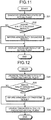
- FIGS. 11 and 12 are flow charts illustrating processing procedures of the plant operation support device according to this example.
- FIG. 11 illustrates the processing procedure for diagnosing the operating state of the actual plant 110 in the plant operating state diagnosis function in the plant operation support device 1.
- FIG. 12 illustrates the processing procedure for diagnosing the operating state of the predicted virtual plant 210' in the plant operating state diagnosis function in the plant operation support device 1.
- the operating state of the actual plant 110 is first diagnosed by the operating state diagnosis unit 21 as illustrated in FIG. 11 (step S21). Specifically, the operating state data D1 on the actual plant 110 is sent to the operating state diagnosis unit 21.
- the operating state diagnosis unit 21 reads diagnosis data D3 from the diagnosis data storage unit 22 according to the operating state data D1, and compares the data D1 and the data D3.
- the abnormality diagnosis result is informed (step S23).
- the abnormality diagnosis result may be informed simply by displaying the result on the diagnosis result display unit 24 by the diagnosis result displaying unit 23 (step S24).
- the abnormality diagnosis result may also be informed by a buzzer and/or a voice message not illustrated in the drawing.
- the abnormality diagnosis result herein refers to the case where inconsistency is present between the data D1 and the data D3.
- step S22 when the diagnosis result of diagnosing the operating state of the actual plant 110 by the operating state diagnosis unit 21 is not an abnormality diagnosis result (step S22: No), the diagnosis result is displayed on the diagnosis result display unit 24 by the diagnosis result displaying unit 23 (step S24).
- the operating state of the predicted virtual plant 210' is first diagnosed by the operating state diagnosis unit 21 as illustrated in FIG. 11 (step S25). Specifically, the operating state of the predicted virtual plant 210' is acquired from the operating state prediction unit 13, and is sent to the operating state diagnosis unit 21. The operating state diagnosis unit 21 reads diagnosis data D3 from the diagnosis data storage unit 22 according to the operating state, and compares these.
- the abnormality diagnosis result is informed (step S27).
- the abnormality diagnosis result may be informed simply by displaying the result on the diagnosis result display unit 24 by the diagnosis result displaying unit 23 (step S28).
- the abnormality diagnosis result may also be informed by a buzzer and/or a voice message not illustrated in the drawing.
- the abnormality diagnosis result herein refers to the case where inconsistency is present between the data D1 and the data D3.
- diagnosis result of the operating state diagnosis unit 21 diagnosing the operating state of the predicted virtual plant 210' is not an abnormality diagnosis result (step S26: No)
- diagnosis result is displayed on the diagnosis result display unit 24 by the diagnosis result displaying unit 23 (step S28).
- the plant operation support device 1 of this example includes the operating state diagnosis unit 21 for diagnosing the operating state of the actual plant 110 while diagnosing the operating state of the predicted virtual plant 210', and the diagnosis result displaying unit 23 for displaying the diagnosis result of the actual plant 110 and the diagnosis result of the predicted virtual plant 210'.
- the plant operation support method of this example also includes an operating state diagnosis step of diagnosing the operating state of the actual plant 110 while diagnosing the operating state of the predicted virtual plant 210', and a diagnosis result display step of displaying the diagnosis result of the actual plant 110 and the diagnosis result of the predicted virtual plant 210'.
- the operating state of the actual plant 110 is diagnosed, while the operating state of the predicted virtual plant 210', which is created as a result of correct and rapid prediction in response to the change in the operating state of the actual plant 110 in the plant operating state prediction function, is diagnosed, so that comparison of both the diagnosis results in accordance with the prediction can correctly and promptly be performed.
- the plant operation procedure presentation function includes operation procedure setting unit 31, operation procedure data storage unit 32, and operation procedure displaying unit 33 as illustrated in FIG. 9 .
- the operation procedure setting unit 31 which corresponds to the diagnosis result in the aforementioned plant operating state diagnosis function, sets operation procedures of the actual plant 110 while setting operation procedures of the predicted virtual plant 210'.
- the diagnosis result of the actual plant 110 is acquired from the operating state diagnosis unit 21, and the operation procedures of the actual plant 110 are set on the basis of the diagnosis result.
- the diagnosis result of the predicted virtual plant 210' is acquired from the operating state diagnosis unit 21, and the operation procedures of the predicted virtual plant 210' are set on the basis of the diagnosis result.
- the operation procedure data storage unit 32 is a data base storing in advance operation procedure data D4 conformed to the result of diagnosing the operating states of the actual plant 110 and/or the predicted virtual plant 210'.
- the operation procedure data D4 includes, for example, operation procedures corresponding to change in such data as parameter diagnosis data indicating parameters, such as a water level, a pressure, and a flow rate of the nuclear reactor 112, device diagnosis data indicating the state of respective systems and the state of respective devices, and alarm diagnosis data when abnormality occurs.
- the operation procedure data D4 is read in setting operation performed by the operation procedure setting unit 31.
- the operation procedure displaying unit 33 is configured to display the operation procedures set for the actual plant 110 and the predicted virtual plant 210'.
- the operation procedures of the actual plant 110 and the predicted virtual plant 210' are input from the operation procedure setting unit 31.
- the operation procedures of the actual plant 110 and the predicted virtual plant 210' are displayed, for example, on an operation procedure display unit 34 in the large-size indicator panel 142 placed in the central control room (not illustrate) including the central control device 140.
- the operation procedure displaying unit 33 makes the operation procedure display unit 34 switch and display either the operation procedures of the actual plant 110 or the operation procedures of the predicted virtual plant 210', and/or display both the operating procedures.
- FIGS. 13 and 14 are flow charts illustrating processing procedures of the plant operation support device according to this example.
- FIG. 13 illustrates the processing procedures for setting the operation procedures of the actual plant 110 in the plant operation procedure presentation function in the plant operation support device 1.
- FIG. 14 illustrates the processing procedures for setting the operation procedures of the predicted virtual plant 210' in the plant operation procedure presentation function in the plant operation support device 1.
- the operation procedures of the actual plant 110 are first set by the operation procedure setting unit 31 as illustrated in FIG. 13 (step S31). Specifically, the operating state of the actual plant 110 diagnosed by the operating state diagnosis unit 21 is sent to the operation procedure setting unit 31.
- the operation procedure setting unit 31 reads the operation procedure data D4 from the operation procedure data storage unit 32 according to the operating state, and sets the operation procedures on the basis of this operation procedure data D4.
- step S32 the operation procedures of the actual plant 110 set by the operation procedure setting unit 31 are displayed on the operation procedure display unit 34 by the operation procedure displaying unit 33.
- the operation procedures of the predicted virtual plant 210' are first set by the operation procedure setting unit 31 as illustrated in FIG. 14 (step S33). Specifically, the operating state of the predicted virtual plant 210' diagnosed by the operating state diagnosis unit 21 is sent to the operation procedure setting unit 31.
- the operation procedure setting unit 31 reads the operation procedure data D4 from the operation procedure data storage unit 32 according to the operating state, and sets the operation procedure on the basis of this operation procedure data D4.
- step S34 the operation procedures of the predicted virtual plant 210' set by the operation procedure setting unit 31 are displayed on the operation procedure display unit 34 by the operation procedure displaying unit 33 (step S34) .
- the plant operation support device 1 of this example includes the operation procedure setting unit 31 for setting the operation procedures corresponding to the diagnosis result of the actual plant 110, while setting the operation procedures corresponding to the diagnosis result of the predicted virtual plant 210', and the operation procedure displaying unit 33 for displaying the operation procedures of the actual plant 110 and the operation procedures of the predicted virtual plant 210' .
- the plant operation support method of this example includes an operation procedure setting step of setting the operation procedures corresponding to the diagnosis result of the actual plant 110, while setting the operation procedures corresponding to the diagnosis result of the predicted virtual plant 210', and an operation procedure display step of displaying the operation procedures of the actual plant 110 and the operation procedures of the predicted virtual plant 210'.
- the operation procedures of the actual plant 110 are set, while the operation procedures of the predicted virtual plant 210', which is created as a result of correct and rapid prediction in response to the change in the operating state of the actual plant 110 in the plant operating state prediction function, are set so that setting of the operation procedures in accordance with the prediction can correctly and promptly be performed.
- the operation confirmation function includes operation confirmation unit 41 and confirmation result displaying unit 42 as illustrated in FIG. 9 .
- the operation confirmation unit 41 which corresponds to setting of the operation procedures in the aforementioned plant operation procedure presentation function, confirms whether or not the operation of the actual plant 110 is in conformity with the operation procedure.
- the operating state data D1 is acquired, while the set operation procedures are acquired from the operation procedure setting unit 31, and the operating state data D1 and the operation procedure are compared for confirmation.
- the operation confirmation unit 41 is configured to display the result of confirming the operation of the actual plant 110.
- the result of confirming the operation of the actual plant 110 is input from the operation confirmation unit 41.
- the result of confirming the operation of the actual plant 110 is displayed, for example, on a confirmation result display unit 43 in the large-size indicator panel 142 placed in the central control room (not illustrate) including the central control device 140.
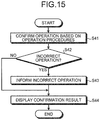
- FIG. 15 is a flow chart illustrating processing procedures of the plant operation support device according to this example.
- FIG. 15 illustrates the processing procedures for confirming the operation of the actual plant 110 in the operation confirmation function in the plant operation support device 1.
- step S41 For confirmation of the operation of the actual plant 110, the operation is first confirmed by the operation confirmation unit 41 on the basis of the operation procedures as illustrated in FIG. 15 (step S41). Specifically, after the operation based on the operation procedures is performed, the operating state data D1 on the actual plant 110 is sent to the operation confirmation unit 41, while the set operation procedures are sent from the operation procedure setting unit 31, and both the operating state data D1 and the operation procedures are compared.
- step S42 when the confirmation result of confirming the operation of the actual plant 110 by the operation confirmation unit 41 is an incorrect operation (step S42: Yes), the incorrect operation is informed (step S43).
- the incorrect operation may be informed simply by displaying the result on the confirmation result display unit 43 by the confirmation result displaying unit 42 (step S44).
- the incorrect operation may also be informed by a buzzer and/or a voice message not illustrated in the drawing.
- the incorrect operation herein refers to the case where the operation in the operating state data D1 is different from the operation in the set operation procedures.
- step S42 when the confirmation result of confirming the operation of the actual plant 110 by the operation confirmation unit 41 is not an incorrect operation (step S42: No), the confirmation result is displayed on the confirmation result display unit 43 by the confirmation result displaying unit 42 (step S44).
- the plant operation support device 1 of this example includes the operation confirmation unit 41 for confirming whether or not the operation of the actual plant 110 is in conformity with the operation procedures, and the confirmation result displaying unit 42 for displaying the confirmation result of the operation.
- the plant operation support method of this example includes an operation confirmation step of confirming whether or not the operation of the actual plant 110 is in conformity with the operation procedure, and a confirmation result display step of displaying the confirmation result of the operation.
Landscapes
- Engineering & Computer Science (AREA)
- Physics & Mathematics (AREA)
- General Engineering & Computer Science (AREA)
- Plasma & Fusion (AREA)
- High Energy & Nuclear Physics (AREA)
- Testing And Monitoring For Control Systems (AREA)
- Monitoring And Testing Of Nuclear Reactors (AREA)
Claims (7)
- Dispositif de commande central (140) prévu pour surveiller et commander une centrale nucléaire (110), le dispositif de commande central (140) comportant :un dispositif d'opération de surveillance (411 ; 412 ; 413), le dispositif d'opération de surveillance étant prévu à la fois comme une unité d'affichage configurée pour afficher de l'information sur la centrale nucléaire (110) et une unité de fonctionnement configurée pour faire fonctionner la centrale nucléaire (110) ; etune unité d'affichage visuel de document de procédure de fonctionnement (414), l'unité d'affichage visuel de document de procédure de fonctionnement étant prévue à la fois comme une unité d'affichage configurée pour afficher un document de procédure de fonctionnement et également comme une unité de fonctionnement configurée pour faire fonctionner la centrale nucléaire ; etune unité de commande (143) configurée pour commander le dispositif d'opération de surveillance (411 ; 412 ; 413) et l'unité d'affichage visuel de document de procédure de fonctionnement (414), dans lequell'unité de commande (143) est configurée pour sélectionner le document de procédure de fonctionnement correspondant à une opération d'entrée dans l'unité de fonctionnement du dispositif d'opération de surveillance (411 ; 412 ; 413) et pour afficher le document de procédure de fonctionnement sur le dispositif d'opération de surveillance (411 ; 412 ; 413) et sur l'unité d'affichage visuel de document de procédure de fonctionnement (414).
- Dispositif de commande central (140) selon la revendication 1, dans lequel l'unité de commande (143) est prévue pour afficher une alarme sur le dispositif d'opération de surveillance (411 ; 412 ; 413) quand une anomalie se produit dans la centrale nucléaire (110).
- Dispositif de commande central (140) selon la revendication 1 ou 2, dans lequel l'unité de commande (143) est prévue pour diagnostiquer un état de la centrale nucléaire (110) et pour afficher un résultat de diagnostic sur le dispositif d'opération de surveillance (411 ; 412 ; 413) .
- Dispositif de commande central (140) selon l'une quelconque des revendications 1 à 3, dans lequel l'unité de commande (143) est prévue pour afficher le document de procédure de fonctionnement et de l'information sur la centrale nucléaire (110) prescrite dans le document de procédure de fonctionnement en association l'un avec l'autre sur le dispositif d'opération de surveillance (411 ; 412 ; 413).
- Dispositif de commande central (140) selon l'une quelconque des revendications 1 à 4, dans lequel l'unité de commande (143) est prévue pour diagnostiquer une transition dans une quantité d'état de la centrale nucléaire (110) pendant un fonctionnement stabilisé et pour afficher un résultat de diagnostic sur le dispositif d'opération de surveillance (411 ; 412 ; 413).
- Dispositif de commande central (140) selon l'une quelconque des revendications 1 à 5, dans lequel l'unité de commande (143) est prévue pour enregistrer une opération correspondante prescrite dans le document de procédure de fonctionnement affiché sur le dispositif d'opération de surveillance (411 ; 412 ; 413) et l'opération d'entrée dans l'unité de fonctionnement du dispositif d'opération de surveillance (411 ; 412 ; 413) en association l'une avec l'autre.
- Dispositif de commande central (140) selon l'une quelconque des revendications 1 à 6, dans lequel l'unité de commande (143) est prévue pour détecter une incohérence entre l'opération correspondante prescrite dans le document de procédure de fonctionnement affiché sur le dispositif d'opération de surveillance (411 ; 412 ; 413) et l'opération d'entrée dans l'unité de fonctionnement du dispositif d'opération de surveillance (411 ; 412 ; 413).
Priority Applications (1)
| Application Number | Priority Date | Filing Date | Title |
|---|---|---|---|
| EP16200780.1A EP3154062B1 (fr) | 2012-03-26 | 2013-03-18 | Dispositif d'assistance au fonctionnement et procédé d'aide au fonctionnement d'une centrale nucléaire |
Applications Claiming Priority (3)
| Application Number | Priority Date | Filing Date | Title |
|---|---|---|---|
| JP2012070314A JP6037635B2 (ja) | 2012-03-26 | 2012-03-26 | 原子力プラントの中央制御装置 |
| JP2012258023A JP6192925B2 (ja) | 2012-11-26 | 2012-11-26 | プラント運転支援装置およびプラント運転支援方法 |
| PCT/JP2013/057690 WO2013146432A1 (fr) | 2012-03-26 | 2013-03-18 | Dispositif de commande centrale pour centrale nucléaire, dispositif d'aide d'opération de centrale et procédé d'aide d'opération de centrale |
Related Child Applications (2)
| Application Number | Title | Priority Date | Filing Date |
|---|---|---|---|
| EP16200780.1A Division-Into EP3154062B1 (fr) | 2012-03-26 | 2013-03-18 | Dispositif d'assistance au fonctionnement et procédé d'aide au fonctionnement d'une centrale nucléaire |
| EP16200780.1A Division EP3154062B1 (fr) | 2012-03-26 | 2013-03-18 | Dispositif d'assistance au fonctionnement et procédé d'aide au fonctionnement d'une centrale nucléaire |
Publications (3)
| Publication Number | Publication Date |
|---|---|
| EP2840577A1 EP2840577A1 (fr) | 2015-02-25 |
| EP2840577A4 EP2840577A4 (fr) | 2016-05-18 |
| EP2840577B1 true EP2840577B1 (fr) | 2017-12-27 |
Family
ID=49259693
Family Applications (2)
| Application Number | Title | Priority Date | Filing Date |
|---|---|---|---|
| EP16200780.1A Active EP3154062B1 (fr) | 2012-03-26 | 2013-03-18 | Dispositif d'assistance au fonctionnement et procédé d'aide au fonctionnement d'une centrale nucléaire |
| EP13767260.6A Active EP2840577B1 (fr) | 2012-03-26 | 2013-03-18 | Dispositif de commande centrale pour centrale nucléaire |
Family Applications Before (1)
| Application Number | Title | Priority Date | Filing Date |
|---|---|---|---|
| EP16200780.1A Active EP3154062B1 (fr) | 2012-03-26 | 2013-03-18 | Dispositif d'assistance au fonctionnement et procédé d'aide au fonctionnement d'une centrale nucléaire |
Country Status (3)
| Country | Link |
|---|---|
| US (1) | US20150049851A1 (fr) |
| EP (2) | EP3154062B1 (fr) |
| WO (1) | WO2013146432A1 (fr) |
Families Citing this family (17)
| Publication number | Priority date | Publication date | Assignee | Title |
|---|---|---|---|---|
| JP6262255B2 (ja) | 2014-01-06 | 2018-01-17 | 三菱重工業株式会社 | 緊急時の意思決定支援システム |
| JP5680784B1 (ja) * | 2014-08-04 | 2015-03-04 | 株式会社テイエルブイ | 蒸気利用設備の管理方法、及び、蒸気利用設備 |
| CN104331064B (zh) * | 2014-10-10 | 2017-02-01 | 中国航天科技集团公司第四研究院第四十一研究所 | 一种用于测控设备的双向供电控制电路及其控制方法 |
| CN104392752B (zh) * | 2014-10-13 | 2016-11-30 | 中国科学院合肥物质科学研究院 | 一种实时在线的核反应堆故障诊断与监测系统 |
| US10254138B2 (en) | 2015-03-31 | 2019-04-09 | Mitsubishi Heavy Industries, Ltd. | Display generating device, display control device, and display generating method |
| WO2016158800A1 (fr) | 2015-03-31 | 2016-10-06 | 三菱重工業株式会社 | Système et procédé de planification d'itinéraire, système et procédé de planification d'agencement d'articles, système d'aide à la décision, programme informatique et support de stockage |
| JP6596261B2 (ja) | 2015-08-19 | 2019-10-23 | 三菱重工業株式会社 | 原子力プラントの電子手順書表示装置、安全系制御監視システム、及び運転監視システム |
| US10460847B2 (en) * | 2016-01-19 | 2019-10-29 | Information Systems Laboratories, Inc. | Gravity-based, non-invasive reactor system and method for coolant inventory monitoring |
| KR101698342B1 (ko) * | 2016-07-27 | 2017-01-20 | 한국수력원자력 주식회사 | 원자력발전소 디지털 주제어실 화면공유시스템 |
| JP6837893B2 (ja) * | 2017-03-31 | 2021-03-03 | 住友重機械工業株式会社 | 故障診断システム |
| CN108303971B (zh) * | 2018-02-28 | 2023-11-03 | 中国船舶重工集团公司第七一九研究所 | 海洋核动力平台的核安全工程师操控台及操控系统 |
| TWI728317B (zh) * | 2019-02-27 | 2021-05-21 | 敏 陳 | 核能發電設備的安全控制系統 |
| CN110400646B (zh) * | 2019-04-28 | 2024-07-09 | 北京广利核系统工程有限公司 | 应用于核电站安全级dcs的人机交互装置、系统及方法 |
| CN111524622B (zh) * | 2020-03-19 | 2022-10-18 | 岭东核电有限公司 | 核电站机组故障报警定位方法、系统、计算机设备及介质 |
| CN113701519B (zh) * | 2021-08-16 | 2023-09-29 | 中国能源建设集团江苏省电力设计院有限公司 | 一种主汽机和小汽机分设凝汽器下的循环水系统优化方法 |
| CN113760433B (zh) * | 2021-09-06 | 2023-12-15 | 中广核工程有限公司 | 面向顺序控制的核电厂监控方法、系统和计算机设备 |
| CN115019392A (zh) * | 2022-06-01 | 2022-09-06 | 中广核工程有限公司 | 控制系统的在线预警方法、装置、计算机设备及介质 |
Family Cites Families (8)
| Publication number | Priority date | Publication date | Assignee | Title |
|---|---|---|---|---|
| JPS5717894A (en) * | 1980-07-07 | 1982-01-29 | Nippon Atomic Ind Group Co | Operator supporting system for atomic power plant |
| US4711753A (en) * | 1986-03-19 | 1987-12-08 | Westinghouse Electric Corp. | Calibration of a nuclear reactor core parameter predictor |
| US4815014A (en) * | 1987-02-27 | 1989-03-21 | Westinghouse Electric Corp. | Machine assisted execution of process operating procedures |
| JPH0961587A (ja) * | 1995-08-24 | 1997-03-07 | Hitachi Ltd | プラント運転監視方法及びその装置 |
| JPH1020924A (ja) * | 1996-07-03 | 1998-01-23 | Toshiba Corp | プラント監視装置 |
| JP3964568B2 (ja) | 1999-02-26 | 2007-08-22 | 東京電力株式会社 | 画像情報表示方法及び装置 |
| JP2000266888A (ja) * | 1999-03-17 | 2000-09-29 | Central Res Inst Of Electric Power Ind | 原子炉の運転支援方法および運転支援装置並びに記録媒体 |
| JP4607702B2 (ja) | 2005-08-10 | 2011-01-05 | 株式会社東芝 | プラント運転支援装置およびプラント運転支援方法 |
-
2013
- 2013-03-18 EP EP16200780.1A patent/EP3154062B1/fr active Active
- 2013-03-18 EP EP13767260.6A patent/EP2840577B1/fr active Active
- 2013-03-18 WO PCT/JP2013/057690 patent/WO2013146432A1/fr not_active Ceased
- 2013-03-18 US US14/387,118 patent/US20150049851A1/en not_active Abandoned
Non-Patent Citations (1)
| Title |
|---|
| None * |
Also Published As
| Publication number | Publication date |
|---|---|
| WO2013146432A1 (fr) | 2013-10-03 |
| EP2840577A1 (fr) | 2015-02-25 |
| US20150049851A1 (en) | 2015-02-19 |
| EP3154062B1 (fr) | 2019-07-31 |
| EP3154062A1 (fr) | 2017-04-12 |
| EP2840577A4 (fr) | 2016-05-18 |
Similar Documents
| Publication | Publication Date | Title |
|---|---|---|
| EP2840577B1 (fr) | Dispositif de commande centrale pour centrale nucléaire | |
| US11551824B2 (en) | Control room for nuclear power plant | |
| CN102156449B (zh) | 核电机组总体程序的数字化方法、系统及dcs控制系统 | |
| EP2650884A1 (fr) | Système de commande numérisé pour une centrale nucléaire, procédé de traitement d'information et dispositif pour ledit système | |
| JP2011095095A (ja) | 原子力発電プラントの運転支援装置及び運転支援方法 | |
| US6163740A (en) | Integrated iconic display for power plants by displaying plurality of process icons corresponding to all operating heat engines in one single computer screen | |
| GB2272325A (en) | Plant monitor system | |
| KR100191566B1 (ko) | 원자력 발전소 제어 컴플렉스에서 지시기의 유효화 방법 | |
| JP6037635B2 (ja) | 原子力プラントの中央制御装置 | |
| JP6192925B2 (ja) | プラント運転支援装置およびプラント運転支援方法 | |
| Yu et al. | Process control evolution and challenges in nuclear power plants | |
| Husseiny et al. | Operating procedure automation to enhance safety of nuclear power plants | |
| JP5416069B2 (ja) | 警報処理システム | |
| Lew et al. | Computerized operator support system for nuclear power plant hybrid main control room | |
| JP2646115B2 (ja) | 試験監視制御装置及び方法 | |
| JP3893563B2 (ja) | 制御棒位置表示装置 | |
| JP3659417B2 (ja) | 制御棒操作監視装置 | |
| JP7433171B2 (ja) | 表示装置、プラント運転支援システムおよびプラント運転支援方法 | |
| CN115116641B (zh) | 核电厂火灾后果监测方法、系统及存储介质 | |
| Suh et al. | An overview of instrumentation and control systems of a Korea standard nuclear power plant: A signal interface standpoint | |
| Pelo | Evaluation of an advanced fault detection system using Koeberg nuclear power plant data | |
| Fujii et al. | BWR Plant Advanced Central Control Panel----PODIA | |
| JP2014178829A (ja) | プラント情報表示システム及びプラント情報表示方法 | |
| JPH02224001A (ja) | 異常原因判定装置 | |
| Jang et al. | System design strategies of post-accident monitoring system for a PGSFR in Korea |
Legal Events
| Date | Code | Title | Description |
|---|---|---|---|
| PUAI | Public reference made under article 153(3) epc to a published international application that has entered the european phase |
Free format text: ORIGINAL CODE: 0009012 |
|
| 17P | Request for examination filed |
Effective date: 20140924 |
|
| AK | Designated contracting states |
Kind code of ref document: A1 Designated state(s): AL AT BE BG CH CY CZ DE DK EE ES FI FR GB GR HR HU IE IS IT LI LT LU LV MC MK MT NL NO PL PT RO RS SE SI SK SM TR |
|
| AX | Request for extension of the european patent |
Extension state: BA ME |
|
| DAX | Request for extension of the european patent (deleted) | ||
| RIC1 | Information provided on ipc code assigned before grant |
Ipc: G21C 17/00 20060101AFI20151019BHEP Ipc: G05B 23/02 20060101ALI20151019BHEP |
|
| RA4 | Supplementary search report drawn up and despatched (corrected) |
Effective date: 20160420 |
|
| RIC1 | Information provided on ipc code assigned before grant |
Ipc: G21D 3/00 20060101ALI20160414BHEP Ipc: G21C 17/00 20060101AFI20160414BHEP Ipc: G05B 23/02 20060101ALI20160414BHEP |
|
| GRAP | Despatch of communication of intention to grant a patent |
Free format text: ORIGINAL CODE: EPIDOSNIGR1 |
|
| INTG | Intention to grant announced |
Effective date: 20170712 |
|
| GRAS | Grant fee paid |
Free format text: ORIGINAL CODE: EPIDOSNIGR3 |
|
| GRAA | (expected) grant |
Free format text: ORIGINAL CODE: 0009210 |
|
| AK | Designated contracting states |
Kind code of ref document: B1 Designated state(s): AL AT BE BG CH CY CZ DE DK EE ES FI FR GB GR HR HU IE IS IT LI LT LU LV MC MK MT NL NO PL PT RO RS SE SI SK SM TR |
|
| REG | Reference to a national code |
Ref country code: GB Ref legal event code: FG4D |
|
| REG | Reference to a national code |
Ref country code: CH Ref legal event code: EP |
|
| REG | Reference to a national code |
Ref country code: AT Ref legal event code: REF Ref document number: 958947 Country of ref document: AT Kind code of ref document: T Effective date: 20180115 |
|
| REG | Reference to a national code |
Ref country code: IE Ref legal event code: FG4D |
|
| REG | Reference to a national code |
Ref country code: DE Ref legal event code: R096 Ref document number: 602013031391 Country of ref document: DE |
|
| REG | Reference to a national code |
Ref country code: FR Ref legal event code: PLFP Year of fee payment: 6 |
|
| PG25 | Lapsed in a contracting state [announced via postgrant information from national office to epo] |
Ref country code: LT Free format text: LAPSE BECAUSE OF FAILURE TO SUBMIT A TRANSLATION OF THE DESCRIPTION OR TO PAY THE FEE WITHIN THE PRESCRIBED TIME-LIMIT Effective date: 20171227 Ref country code: NO Free format text: LAPSE BECAUSE OF FAILURE TO SUBMIT A TRANSLATION OF THE DESCRIPTION OR TO PAY THE FEE WITHIN THE PRESCRIBED TIME-LIMIT Effective date: 20180327 Ref country code: FI Free format text: LAPSE BECAUSE OF FAILURE TO SUBMIT A TRANSLATION OF THE DESCRIPTION OR TO PAY THE FEE WITHIN THE PRESCRIBED TIME-LIMIT Effective date: 20171227 |
|
| REG | Reference to a national code |
Ref country code: NL Ref legal event code: MP Effective date: 20171227 |
|
| REG | Reference to a national code |
Ref country code: LT Ref legal event code: MG4D |
|
| REG | Reference to a national code |
Ref country code: AT Ref legal event code: MK05 Ref document number: 958947 Country of ref document: AT Kind code of ref document: T Effective date: 20171227 |
|
| PG25 | Lapsed in a contracting state [announced via postgrant information from national office to epo] |
Ref country code: HR Free format text: LAPSE BECAUSE OF FAILURE TO SUBMIT A TRANSLATION OF THE DESCRIPTION OR TO PAY THE FEE WITHIN THE PRESCRIBED TIME-LIMIT Effective date: 20171227 Ref country code: GR Free format text: LAPSE BECAUSE OF FAILURE TO SUBMIT A TRANSLATION OF THE DESCRIPTION OR TO PAY THE FEE WITHIN THE PRESCRIBED TIME-LIMIT Effective date: 20180328 Ref country code: RS Free format text: LAPSE BECAUSE OF FAILURE TO SUBMIT A TRANSLATION OF THE DESCRIPTION OR TO PAY THE FEE WITHIN THE PRESCRIBED TIME-LIMIT Effective date: 20171227 Ref country code: BG Free format text: LAPSE BECAUSE OF FAILURE TO SUBMIT A TRANSLATION OF THE DESCRIPTION OR TO PAY THE FEE WITHIN THE PRESCRIBED TIME-LIMIT Effective date: 20180327 Ref country code: LV Free format text: LAPSE BECAUSE OF FAILURE TO SUBMIT A TRANSLATION OF THE DESCRIPTION OR TO PAY THE FEE WITHIN THE PRESCRIBED TIME-LIMIT Effective date: 20171227 |
|
| PG25 | Lapsed in a contracting state [announced via postgrant information from national office to epo] |
Ref country code: NL Free format text: LAPSE BECAUSE OF FAILURE TO SUBMIT A TRANSLATION OF THE DESCRIPTION OR TO PAY THE FEE WITHIN THE PRESCRIBED TIME-LIMIT Effective date: 20171227 |
|
| PG25 | Lapsed in a contracting state [announced via postgrant information from national office to epo] |
Ref country code: CY Free format text: LAPSE BECAUSE OF FAILURE TO SUBMIT A TRANSLATION OF THE DESCRIPTION OR TO PAY THE FEE WITHIN THE PRESCRIBED TIME-LIMIT Effective date: 20171227 Ref country code: EE Free format text: LAPSE BECAUSE OF FAILURE TO SUBMIT A TRANSLATION OF THE DESCRIPTION OR TO PAY THE FEE WITHIN THE PRESCRIBED TIME-LIMIT Effective date: 20171227 Ref country code: SK Free format text: LAPSE BECAUSE OF FAILURE TO SUBMIT A TRANSLATION OF THE DESCRIPTION OR TO PAY THE FEE WITHIN THE PRESCRIBED TIME-LIMIT Effective date: 20171227 Ref country code: ES Free format text: LAPSE BECAUSE OF FAILURE TO SUBMIT A TRANSLATION OF THE DESCRIPTION OR TO PAY THE FEE WITHIN THE PRESCRIBED TIME-LIMIT Effective date: 20171227 Ref country code: CZ Free format text: LAPSE BECAUSE OF FAILURE TO SUBMIT A TRANSLATION OF THE DESCRIPTION OR TO PAY THE FEE WITHIN THE PRESCRIBED TIME-LIMIT Effective date: 20171227 |
|
| PG25 | Lapsed in a contracting state [announced via postgrant information from national office to epo] |
Ref country code: PL Free format text: LAPSE BECAUSE OF FAILURE TO SUBMIT A TRANSLATION OF THE DESCRIPTION OR TO PAY THE FEE WITHIN THE PRESCRIBED TIME-LIMIT Effective date: 20171227 Ref country code: AT Free format text: LAPSE BECAUSE OF FAILURE TO SUBMIT A TRANSLATION OF THE DESCRIPTION OR TO PAY THE FEE WITHIN THE PRESCRIBED TIME-LIMIT Effective date: 20171227 Ref country code: SM Free format text: LAPSE BECAUSE OF FAILURE TO SUBMIT A TRANSLATION OF THE DESCRIPTION OR TO PAY THE FEE WITHIN THE PRESCRIBED TIME-LIMIT Effective date: 20171227 Ref country code: IT Free format text: LAPSE BECAUSE OF FAILURE TO SUBMIT A TRANSLATION OF THE DESCRIPTION OR TO PAY THE FEE WITHIN THE PRESCRIBED TIME-LIMIT Effective date: 20171227 Ref country code: RO Free format text: LAPSE BECAUSE OF FAILURE TO SUBMIT A TRANSLATION OF THE DESCRIPTION OR TO PAY THE FEE WITHIN THE PRESCRIBED TIME-LIMIT Effective date: 20171227 Ref country code: IS Free format text: LAPSE BECAUSE OF FAILURE TO SUBMIT A TRANSLATION OF THE DESCRIPTION OR TO PAY THE FEE WITHIN THE PRESCRIBED TIME-LIMIT Effective date: 20180427 |
|
| REG | Reference to a national code |
Ref country code: DE Ref legal event code: R097 Ref document number: 602013031391 Country of ref document: DE |
|
| REG | Reference to a national code |
Ref country code: DE Ref legal event code: R119 Ref document number: 602013031391 Country of ref document: DE |
|
| REG | Reference to a national code |
Ref country code: CH Ref legal event code: PL |
|
| PLBE | No opposition filed within time limit |
Free format text: ORIGINAL CODE: 0009261 |
|
| STAA | Information on the status of an ep patent application or granted ep patent |
Free format text: STATUS: NO OPPOSITION FILED WITHIN TIME LIMIT |
|
| GBPC | Gb: european patent ceased through non-payment of renewal fee |
Effective date: 20180327 |
|
| PG25 | Lapsed in a contracting state [announced via postgrant information from national office to epo] |
Ref country code: MC Free format text: LAPSE BECAUSE OF FAILURE TO SUBMIT A TRANSLATION OF THE DESCRIPTION OR TO PAY THE FEE WITHIN THE PRESCRIBED TIME-LIMIT Effective date: 20171227 Ref country code: DK Free format text: LAPSE BECAUSE OF FAILURE TO SUBMIT A TRANSLATION OF THE DESCRIPTION OR TO PAY THE FEE WITHIN THE PRESCRIBED TIME-LIMIT Effective date: 20171227 |
|
| 26N | No opposition filed |
Effective date: 20180928 |
|
| REG | Reference to a national code |
Ref country code: BE Ref legal event code: MM Effective date: 20180331 |
|
| REG | Reference to a national code |
Ref country code: IE Ref legal event code: MM4A |
|
| PG25 | Lapsed in a contracting state [announced via postgrant information from national office to epo] |
Ref country code: LU Free format text: LAPSE BECAUSE OF NON-PAYMENT OF DUE FEES Effective date: 20180318 |
|
| PG25 | Lapsed in a contracting state [announced via postgrant information from national office to epo] |
Ref country code: IE Free format text: LAPSE BECAUSE OF NON-PAYMENT OF DUE FEES Effective date: 20180318 Ref country code: DE Free format text: LAPSE BECAUSE OF NON-PAYMENT OF DUE FEES Effective date: 20181002 |
|
| PG25 | Lapsed in a contracting state [announced via postgrant information from national office to epo] |
Ref country code: SI Free format text: LAPSE BECAUSE OF FAILURE TO SUBMIT A TRANSLATION OF THE DESCRIPTION OR TO PAY THE FEE WITHIN THE PRESCRIBED TIME-LIMIT Effective date: 20171227 Ref country code: BE Free format text: LAPSE BECAUSE OF NON-PAYMENT OF DUE FEES Effective date: 20180331 Ref country code: CH Free format text: LAPSE BECAUSE OF NON-PAYMENT OF DUE FEES Effective date: 20180331 Ref country code: GB Free format text: LAPSE BECAUSE OF NON-PAYMENT OF DUE FEES Effective date: 20180327 Ref country code: LI Free format text: LAPSE BECAUSE OF NON-PAYMENT OF DUE FEES Effective date: 20180331 |
|
| PG25 | Lapsed in a contracting state [announced via postgrant information from national office to epo] |
Ref country code: MT Free format text: LAPSE BECAUSE OF NON-PAYMENT OF DUE FEES Effective date: 20180318 |
|
| PG25 | Lapsed in a contracting state [announced via postgrant information from national office to epo] |
Ref country code: TR Free format text: LAPSE BECAUSE OF FAILURE TO SUBMIT A TRANSLATION OF THE DESCRIPTION OR TO PAY THE FEE WITHIN THE PRESCRIBED TIME-LIMIT Effective date: 20171227 |
|
| PG25 | Lapsed in a contracting state [announced via postgrant information from national office to epo] |
Ref country code: PT Free format text: LAPSE BECAUSE OF FAILURE TO SUBMIT A TRANSLATION OF THE DESCRIPTION OR TO PAY THE FEE WITHIN THE PRESCRIBED TIME-LIMIT Effective date: 20171227 |
|
| PG25 | Lapsed in a contracting state [announced via postgrant information from national office to epo] |
Ref country code: SE Free format text: LAPSE BECAUSE OF FAILURE TO SUBMIT A TRANSLATION OF THE DESCRIPTION OR TO PAY THE FEE WITHIN THE PRESCRIBED TIME-LIMIT Effective date: 20171227 Ref country code: HU Free format text: LAPSE BECAUSE OF FAILURE TO SUBMIT A TRANSLATION OF THE DESCRIPTION OR TO PAY THE FEE WITHIN THE PRESCRIBED TIME-LIMIT; INVALID AB INITIO Effective date: 20130318 Ref country code: MK Free format text: LAPSE BECAUSE OF NON-PAYMENT OF DUE FEES Effective date: 20171227 |
|
| PG25 | Lapsed in a contracting state [announced via postgrant information from national office to epo] |
Ref country code: AL Free format text: LAPSE BECAUSE OF FAILURE TO SUBMIT A TRANSLATION OF THE DESCRIPTION OR TO PAY THE FEE WITHIN THE PRESCRIBED TIME-LIMIT Effective date: 20171227 |
|
| P01 | Opt-out of the competence of the unified patent court (upc) registered |
Effective date: 20230522 |
|
| PGFP | Annual fee paid to national office [announced via postgrant information from national office to epo] |
Ref country code: FR Payment date: 20260209 Year of fee payment: 14 |