EP2843233A2 - Récipient doté d'une pompe submersible - Google Patents
Récipient doté d'une pompe submersible Download PDFInfo
- Publication number
- EP2843233A2 EP2843233A2 EP20140002191 EP14002191A EP2843233A2 EP 2843233 A2 EP2843233 A2 EP 2843233A2 EP 20140002191 EP20140002191 EP 20140002191 EP 14002191 A EP14002191 A EP 14002191A EP 2843233 A2 EP2843233 A2 EP 2843233A2
- Authority
- EP
- European Patent Office
- Prior art keywords
- container
- flange
- pump
- outside
- submersible pump
- Prior art date
- Legal status (The legal status is an assumption and is not a legal conclusion. Google has not performed a legal analysis and makes no representation as to the accuracy of the status listed.)
- Withdrawn
Links
- 239000007788 liquid Substances 0.000 claims abstract description 22
- 230000008878 coupling Effects 0.000 claims abstract description 13
- 238000010168 coupling process Methods 0.000 claims abstract description 13
- 238000005859 coupling reaction Methods 0.000 claims abstract description 13
- 238000007789 sealing Methods 0.000 claims description 9
- 238000010276 construction Methods 0.000 claims description 8
- 238000007872 degassing Methods 0.000 claims description 7
- 238000005086 pumping Methods 0.000 description 17
- 238000012423 maintenance Methods 0.000 description 5
- 238000000034 method Methods 0.000 description 4
- 230000008901 benefit Effects 0.000 description 3
- 230000035515 penetration Effects 0.000 description 3
- 239000011344 liquid material Substances 0.000 description 2
- 239000000463 material Substances 0.000 description 2
- 230000000149 penetrating effect Effects 0.000 description 2
- 238000012545 processing Methods 0.000 description 2
- QVGXLLKOCUKJST-UHFFFAOYSA-N atomic oxygen Chemical compound [O] QVGXLLKOCUKJST-UHFFFAOYSA-N 0.000 description 1
- 238000013461 design Methods 0.000 description 1
- 238000004519 manufacturing process Methods 0.000 description 1
- 238000010327 methods by industry Methods 0.000 description 1
- 238000012544 monitoring process Methods 0.000 description 1
- 229910052760 oxygen Inorganic materials 0.000 description 1
- 239000001301 oxygen Substances 0.000 description 1
- 229920003023 plastic Polymers 0.000 description 1
- 239000004033 plastic Substances 0.000 description 1
- 238000004886 process control Methods 0.000 description 1
- 238000003756 stirring Methods 0.000 description 1
Images

Classifications
-
- F—MECHANICAL ENGINEERING; LIGHTING; HEATING; WEAPONS; BLASTING
- F04—POSITIVE - DISPLACEMENT MACHINES FOR LIQUIDS; PUMPS FOR LIQUIDS OR ELASTIC FLUIDS
- F04D—NON-POSITIVE-DISPLACEMENT PUMPS
- F04D13/00—Pumping installations or systems
- F04D13/02—Units comprising pumps and their driving means
- F04D13/021—Units comprising pumps and their driving means containing a coupling
- F04D13/024—Units comprising pumps and their driving means containing a coupling a magnetic coupling
-
- F—MECHANICAL ENGINEERING; LIGHTING; HEATING; WEAPONS; BLASTING
- F04—POSITIVE - DISPLACEMENT MACHINES FOR LIQUIDS; PUMPS FOR LIQUIDS OR ELASTIC FLUIDS
- F04D—NON-POSITIVE-DISPLACEMENT PUMPS
- F04D13/00—Pumping installations or systems
- F04D13/16—Pumping installations or systems with storage reservoirs
Definitions
- the present invention relates to a device having a container volume which can be sealed off from the outside environment and having a submersible pump in a lower region of the container volume, which is adapted to pump liquid in the container out of the container through a line leading outwardly through a container wall.
- the requirement of the absence of bubbles of the material requires the use of negative pressure (so-called vacuum) in the container volume in various such processes for degassing the liquid (in particular for liquids which tend to absorb oxygen).
- vacuum negative pressure
- mechanical means such as stirring or centrifugal units with spoon or blade-like actuators, which act on the liquid in the container interior and are driven from outside the container by suitable motor.
- a penetration of the container wall is required, for example, between the pump or motor outside and vacuum line mouth or actuator inside the required operative connection.
- an upper-side opening is provided with a lid, which is not least also equipped to maintain the vacuum in the container with a sealing construction.
- the line 8' is guided by the lid 10 ', which closes the top-side filling opening 12' of the container 2 '.
- the shaft drive 14 'of the submersible pump 4' is guided by the lid 10 ', and the vacuum pump 16' is flanged here.
- the mechanical operative connection (usually a drive shaft 14 ') thus has to overcome the entire container height from above the cover 10' to the pumping station 4 'at the very bottom of the container.
- the process control requires a device as far as possible the most accurate pressure monitoring in the line 8 'as close to the pumping station 4'.
- sensors can not be there in the container surrounded by liquid attach with turn the disadvantageous consequence that it is usually accepted to attach the sensor 20 'only above the lid 10' outside of the container and therefore the pressure loss in the Can not detect line 8 'on the container height.
- the present invention is based on the object to provide a container with pump of the type described in the introduction, which is process and user-friendly, as well as cost-saving and in particular overcomes the disadvantages mentioned above.
- a device has a container volume which can be sealed off from the outside environment for storing liquid and a submersible pump in a lower region of the container volume, which is set up to pump liquid in the container out of the container through a line which leads through a container wall to the outside ,
- the submersible pump is placed directly in the container volume - and possibly at the lowest point to ensure the most complete emptying and while minimizing sealing measures at the pump to minimize as mentioned at least as possible by the pumping station itself is surrounded by the material to be pumped and therefore not must be sealed against an outside environment.
- the container volume particularly preferably has a particularly top-side opening with lid, which is equipped, for example, for maintaining a vacuum in the container with a sealing construction.
- the submersible pump is driven in rotation by a motor which is arranged outside the container. This is done by means of a magnetic coupling which transmits the drive torque of the motor (in particular from a shaft of the motor) through a container wall, without physically penetrating the wall.
- the drive torque of the motor is thus transmitted by magnetic force of the magnetic coupling to the submersible pump in the lower region of the container, in particular on a submersible pump shaft, which transmits the drive torque in the container interior through the magnetic coupling to the submersible pump.
- the submersible pump can continue to be at the very bottom and a lid for filling the container continue with simple seal construction at the top - but now with the advantageous consequence that the submersible pump down there in the container with drive torque is supplied extremely short-stretched, by a preferably as possible near container wall by means of the magnetic coupling, so that it does not require any seal a (conventionally required) penetration of the container wall (especially not of moving parts such as a drive shaft).
- a simple flange gasket is needed to seal about the containment shell of the magnetic coupling to the flange plate of the container.
- the container wall through which the magnetic coupling transmits the drive torque in the container part of a flange, which has a flange of the Close container tightly to get there easily through to the submersible pumping station.
- the pumping station is mounted on the inside of the flange and can be so easily decrease as the cover is removed.
- the line is preferably also leads through the flange to the outside.
- the conduit path from the pump out of the container can be designed to be extremely advantageously short and designed so that the path of the conduit out of the container is at the same height as the pumping station, without, as in the prior art the submersible pump has to overcome with its performance when pumping the liquid, first the entire container height.
- a pressure sensor and also any other sensors can now also advantageously be arranged very close to the pumping station in the region of the outside of the flange cover (or at least at the exit point of the line from the container) and there to measure the pressure very close to the pumping station in the line the pump is created in the liquid to allow quick and accurate control.
- vacuum can be generated in the container for degassing the liquid by means of a vacuum pump and / or a mechanical degassing device can be provided.
- a vacuum pump and / or a mechanical degassing device can be provided.
- These are then preferably installed in each case in one or in a common flange lid, which tightly seals a flange opening of the container, namely preferably the conventional filling opening of the container.
- This flange cover for the degassing is then the conventional lid of the conventional filling.
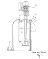
- a device 1 according to the invention Fig. 2 has a tank volume 2 for storing liquid 6, which is tightly sealable with respect to the outside environment, and a submersible pump 4 in a lower area of the container volume 2 which is set up, liquid 6 in the container 2 through a line 8 which leads through a container wall 24 to the outside, to pump out of the container 2.
- a submersible pump 4 in the container volume 2 (surrounded by the liquid 4) is arranged - and possibly at the lowest point to allow the most complete emptying possible with this advantage.
- the container volume 2 has an upper-side opening 12 with lid 10, which is equipped (for maintaining a vacuum in the container 2) with a sealing construction (not shown).
- the submersible pump 4 is rotationally driven by a motor 20 disposed outside of the container 2. This is done by means of a magnetic coupling 21, which transmits the drive torque from a shaft 23 of the motor 20 through a container wall 24, without physically penetrating the wall 24.
- the drive torque of the motor 20 is thus transmitted by magnetic force of the magnetic coupling 21 on the submersible pump 4 in the lower region of the container 2, on a submersible pump shaft (not shown), which transmits the drive torque through the magnetic coupling 21 to the submersible pump 4 in the container interior 2.
- the pump is located in a shaft-like, outwardly projecting arrangement in the bottom structure 26 of the container 2, from the otherwise substantially cylindrical container contour laterally (in Fig. 2 sticking out to the right).
- the submersible pump 4 continues to continue at the bottom and the lid 10 for filling the container 2 through a filling 12 further with simple seal construction at the top of the device 1 - but now with the advantageous technical possibility that the submersible pump. 4 down there in the container 4 with drive torque is supplied extremely short-stretched, namely by a near container wall 24 by means of the magnetic coupling 21, so that it does not require any seal a (conventionally required) penetration of the container wall with a movable part (namely, the drive shaft).
- the container wall 24, by means of which the magnetic coupling 21 transmits the drive torque to the container 2, is part of a flange cover 27, which tightly closes a flange opening 28 of the container 2 in order to get there easily through to the submersible pumping station 4.
- the pumping station 4 is mounted on the inside of the flange cover 27 and can be easily removed with removal of the cover 27 with and out of the interior of the container 2. In particular, for easier disassembly and maintenance and the line 8 is through the flange 27 leads to the outside.
- the conduction path 8 (from the pump 4 out of the container 2) can be designed to be extremely short and so designed that the path of the conduit 8 out of the container 2 is at the same height as the pumping station 4 located - without that is, as in the prior art, the submersible pump 4 has to overcome with their performance in pumping the liquid 6, first, the entire container height.
- a pressure sensor 22 is now also advantageously located very close to the pumping station 4 in the region of the outside of the flange 27 near the exit point of the conduit 8 from the container 2 and measures there (very close to the pumping station 4) in the line 8, the pressure that the pump 4 generated in the liquid 8.
- vacuum can be generated by means of a vacuum pump 32 for degassing the liquid. This communicates with the cover 10 in line connection, which closes the filling opening 12 of the container 2 tight.
Landscapes
- Engineering & Computer Science (AREA)
- Mechanical Engineering (AREA)
- General Engineering & Computer Science (AREA)
- Structures Of Non-Positive Displacement Pumps (AREA)
Applications Claiming Priority (1)
| Application Number | Priority Date | Filing Date | Title |
|---|---|---|---|
| DE201310010590 DE102013010590A1 (de) | 2013-06-26 | 2013-06-26 | Behälter mit Tauchpumpe |
Publications (2)
| Publication Number | Publication Date |
|---|---|
| EP2843233A2 true EP2843233A2 (fr) | 2015-03-04 |
| EP2843233A3 EP2843233A3 (fr) | 2015-04-08 |
Family
ID=51032888
Family Applications (1)
| Application Number | Title | Priority Date | Filing Date |
|---|---|---|---|
| EP20140002191 Withdrawn EP2843233A3 (fr) | 2013-06-26 | 2014-06-26 | Récipient doté d'une pompe submersible |
Country Status (2)
| Country | Link |
|---|---|
| EP (1) | EP2843233A3 (fr) |
| DE (1) | DE102013010590A1 (fr) |
Family Cites Families (9)
| Publication number | Priority date | Publication date | Assignee | Title |
|---|---|---|---|---|
| US3321081A (en) * | 1964-06-18 | 1967-05-23 | Aquariums Inc | Aquarium filter apparatus |
| DE3029044C2 (de) * | 1980-07-31 | 1986-04-30 | Agfa-Gevaert Ag, 5090 Leverkusen | Vorrichtung zum Entwickeln von fotografischen Schichtträgern |
| DE8115960U1 (de) * | 1981-05-29 | 1981-09-24 | Lederle Gmbh Pumpen Und Maschinenfabrik, 7800 Freiburg | "motorpumpen-aggregat" |
| US4645432A (en) * | 1986-02-14 | 1987-02-24 | General Motors Corporation | Magnetic drive vehicle coolant pump |
| DE3729708A1 (de) * | 1986-09-05 | 1988-03-17 | Fuji Photo Film Co Ltd | Magnetpumpe |
| DE9307447U1 (de) * | 1993-05-17 | 1993-07-22 | Friatec-Rheinhütte GmbH & Co., 6200 Wiesbaden | Vertikale Magnetkupplungspumpe bzw. -rührer |
| DE4327735A1 (de) * | 1993-08-18 | 1995-02-23 | Grundfos As | Vorrichtung zum Liefern von Flüssigkeit |
| JP2001295799A (ja) * | 2000-04-14 | 2001-10-26 | Matsushita Refrig Co Ltd | 給水装置およびその給水装置を備えた冷蔵庫と電気ジャーポット |
| EP1318306B1 (fr) * | 2001-12-04 | 2005-06-01 | Levitronix LLC | Dispositif de distribution de liquid |
-
2013
- 2013-06-26 DE DE201310010590 patent/DE102013010590A1/de not_active Withdrawn
-
2014
- 2014-06-26 EP EP20140002191 patent/EP2843233A3/fr not_active Withdrawn
Non-Patent Citations (1)
| Title |
|---|
| None |
Also Published As
| Publication number | Publication date |
|---|---|
| DE102013010590A1 (de) | 2014-12-31 |
| EP2843233A3 (fr) | 2015-04-08 |
Similar Documents
| Publication | Publication Date | Title |
|---|---|---|
| EP2296795A1 (fr) | Système de mélange | |
| WO2015158764A1 (fr) | Balance doseuse différentielle pour le dosage de liquides | |
| EP2843233A2 (fr) | Récipient doté d'une pompe submersible | |
| DE202013005711U1 (de) | Behälter mit Tauchpumpe | |
| DE102011084906A1 (de) | Verfahren zur Überwachung einer Pumpe für Flüssigkeiten und Pumpe | |
| CN201036735Y (zh) | 可视化旋转式混合装置 | |
| DE102020116815A1 (de) | Pump-Einheit, damit ausgestattete Lagervorrichtung sowie Verfahren zum Betreiben der Pump -Einheit | |
| DE102012215330A1 (de) | Rührwerk | |
| DE10101099A1 (de) | Verfahren zum Überwachen des Trockenlaufs einer Förderpumpe und nach dem Verfahren arbeitende Förderpumpe | |
| WO2021078876A1 (fr) | Unité de pompe, dispositif de stockage équipé de celle-ci, et procédé de fonctionnement du dispositif de stockage | |
| EP3441612A1 (fr) | Unité de pompe, dispositif de stockage équipé d'une telle unité de pompe et procédé de fonctionnement dudit dispositif de stockage | |
| CN217576558U (zh) | 一种肉粉混合物存储罐 | |
| DE202007018863U1 (de) | Gär- bzw. Faulbehälter | |
| CN208630946U (zh) | 一种有机硅密封胶的过滤输送装置 | |
| CN103977633A (zh) | 压滤机过滤自动加药系统 | |
| CN212076587U (zh) | 一种根据锅炉水质自动加药的控制系统 | |
| CN203877908U (zh) | 储绒装置 | |
| DE2330922A1 (de) | Vorrichtung zum zufuehren von fuellgut, insbesondere fuer wurstfuellmaschinen | |
| CN209109110U (zh) | 一种润滑油搅拌装置 | |
| CN217262133U (zh) | 一种排出量可控的丙酮储存罐 | |
| CN105013377A (zh) | 一种进料可控的可抽真空的自动搅拌装置 | |
| AT56215B (de) | Wassermesser. | |
| CN206336798U (zh) | 一种防堵自动输料装置 | |
| CN208759952U (zh) | 一种注塑机用胶液分注装置 | |
| CN220737246U (zh) | 一种消毒供应室用消毒液配制装置 |
Legal Events
| Date | Code | Title | Description |
|---|---|---|---|
| 17P | Request for examination filed |
Effective date: 20140626 |
|
| AK | Designated contracting states |
Kind code of ref document: A2 Designated state(s): AL AT BE BG CH CY CZ DE DK EE ES FI FR GB GR HR HU IE IS IT LI LT LU LV MC MK MT NL NO PL PT RO RS SE SI SK SM TR |
|
| AX | Request for extension of the european patent |
Extension state: BA ME |
|
| PUAI | Public reference made under article 153(3) epc to a published international application that has entered the european phase |
Free format text: ORIGINAL CODE: 0009012 |
|
| PUAL | Search report despatched |
Free format text: ORIGINAL CODE: 0009013 |
|
| AK | Designated contracting states |
Kind code of ref document: A3 Designated state(s): AL AT BE BG CH CY CZ DE DK EE ES FI FR GB GR HR HU IE IS IT LI LT LU LV MC MK MT NL NO PL PT RO RS SE SI SK SM TR |
|
| AX | Request for extension of the european patent |
Extension state: BA ME |
|
| RIC1 | Information provided on ipc code assigned before grant |
Ipc: F04D 13/16 20060101ALI20150304BHEP Ipc: F04D 13/02 20060101AFI20150304BHEP |
|
| R17P | Request for examination filed (corrected) |
Effective date: 20151008 |
|
| RBV | Designated contracting states (corrected) |
Designated state(s): AL AT BE BG CH CY CZ DE DK EE ES FI FR GB GR HR HU IE IS IT LI LT LU LV MC MK MT NL NO PL PT RO RS SE SI SK SM TR |
|
| STAA | Information on the status of an ep patent application or granted ep patent |
Free format text: STATUS: REQUEST FOR EXAMINATION WAS MADE |
|
| STAA | Information on the status of an ep patent application or granted ep patent |
Free format text: STATUS: THE APPLICATION IS DEEMED TO BE WITHDRAWN |
|
| 18D | Application deemed to be withdrawn |
Effective date: 20170103 |