EP2843680A2 - Commutateur thermique - Google Patents
Commutateur thermique Download PDFInfo
- Publication number
- EP2843680A2 EP2843680A2 EP14179631.8A EP14179631A EP2843680A2 EP 2843680 A2 EP2843680 A2 EP 2843680A2 EP 14179631 A EP14179631 A EP 14179631A EP 2843680 A2 EP2843680 A2 EP 2843680A2
- Authority
- EP
- European Patent Office
- Prior art keywords
- plunger
- temperature
- spring
- switch according
- dependent switch
- Prior art date
- Legal status (The legal status is an assumption and is not a legal conclusion. Google has not performed a legal analysis and makes no representation as to the accuracy of the status listed.)
- Granted
Links
Images


Classifications
-
- H—ELECTRICITY
- H01—ELECTRIC ELEMENTS
- H01H—ELECTRIC SWITCHES; RELAYS; SELECTORS; EMERGENCY PROTECTIVE DEVICES
- H01H37/00—Thermally-actuated switches
- H01H37/02—Details
- H01H37/32—Thermally-sensitive members
- H01H37/52—Thermally-sensitive members actuated due to deflection of bimetallic element
- H01H37/54—Thermally-sensitive members actuated due to deflection of bimetallic element wherein the bimetallic element is inherently snap acting
-
- H—ELECTRICITY
- H01—ELECTRIC ELEMENTS
- H01H—ELECTRIC SWITCHES; RELAYS; SELECTORS; EMERGENCY PROTECTIVE DEVICES
- H01H37/00—Thermally-actuated switches
- H01H37/02—Details
- H01H37/32—Thermally-sensitive members
- H01H37/52—Thermally-sensitive members actuated due to deflection of bimetallic element
- H01H37/54—Thermally-sensitive members actuated due to deflection of bimetallic element wherein the bimetallic element is inherently snap acting
- H01H37/5427—Thermally-sensitive members actuated due to deflection of bimetallic element wherein the bimetallic element is inherently snap acting encapsulated in sealed miniaturised housing
-
- H—ELECTRICITY
- H01—ELECTRIC ELEMENTS
- H01H—ELECTRIC SWITCHES; RELAYS; SELECTORS; EMERGENCY PROTECTIVE DEVICES
- H01H1/00—Contacts
- H01H1/12—Contacts characterised by the manner in which co-operating contacts engage
- H01H1/14—Contacts characterised by the manner in which co-operating contacts engage by abutting
- H01H1/24—Contacts characterised by the manner in which co-operating contacts engage by abutting with resilient mounting
- H01H1/26—Contacts characterised by the manner in which co-operating contacts engage by abutting with resilient mounting with spring blade support
-
- H—ELECTRICITY
- H01—ELECTRIC ELEMENTS
- H01H—ELECTRIC SWITCHES; RELAYS; SELECTORS; EMERGENCY PROTECTIVE DEVICES
- H01H37/00—Thermally-actuated switches
- H01H37/02—Details
- H01H37/32—Thermally-sensitive members
- H01H37/52—Thermally-sensitive members actuated due to deflection of bimetallic element
- H01H37/54—Thermally-sensitive members actuated due to deflection of bimetallic element wherein the bimetallic element is inherently snap acting
- H01H2037/549—Details of movement transmission between bimetallic snap element and contact
-
- H—ELECTRICITY
- H01—ELECTRIC ELEMENTS
- H01H—ELECTRIC SWITCHES; RELAYS; SELECTORS; EMERGENCY PROTECTIVE DEVICES
- H01H37/00—Thermally-actuated switches
- H01H37/02—Details
- H01H37/32—Thermally-sensitive members
- H01H37/52—Thermally-sensitive members actuated due to deflection of bimetallic element
- H01H37/54—Thermally-sensitive members actuated due to deflection of bimetallic element wherein the bimetallic element is inherently snap acting
- H01H37/5418—Thermally-sensitive members actuated due to deflection of bimetallic element wherein the bimetallic element is inherently snap acting using cantilevered bimetallic snap elements
Definitions
- the present invention relates to a temperature-dependent switch having a first and a second outer terminal, a stationary contact part electrically conductively connected to the first outer terminal, a movable contact part cooperating with the stationary contact part and attached to a spring part which is electrically conductively connected to the second outer terminal is, and which presses the movable contact part against the stationary contact part, a bimetallic element and disposed between the bimetallic part and the spring member plunger, the bimetallic part exerts pressure forces on the spring member on exceeding a switching temperature on the plunger and thereby the movable contact part of the stationary contact part takes off.
- Such a switch is from the DE 10 2011 016 896 B3 known.
- the well-known switch is temperature protection switch, in which by the switching movement of a bimetallic disc via a plunger pressure forces are transmitted to a current-carrying spring part, which acts here as a closing spring.
- the closing spring carries a movable contact part, which presses it with a closed switch against a stationary contact part.
- Stationary contact part and closing spring are each connected to a connecting plate.
- the two connection plates are fixed to an insulator body, from which they protrude laterally.
- the temperature protection switch has a flat housing from which the two connection plates protrude as external connections.
- Such temperature-dependent switches are used in a known manner to protect electrical equipment from overheating.
- the switch is electrically connected via its two external connections with the device to be protected in series and mechanically arranged on the device so that it is in thermal communication with this.
- a switch according to the DE 44 28 226 C1 is arranged in a housing, a temperature-dependent switching mechanism of Federschnappulation, bimetallic snap disk and movable contact part, which is in the closed state of the switch in contact with a stationary contact part inside the upper part, which is plated through to the outside to a first terminal on the upper part.
- the second connection is the conductive lower part.
- the operating current of the device to be protected flows through the two contact parts and the spring snap disc in the lower part.
- the from the DE 44 28 226 C1 Known switch is provided with an electrically arranged in series with the outer terminals heating resistor, which provides a current-dependent switching function.
- the operating current of the device to be protected thus flows constantly through this heating resistor, which can be dimensioned so that it ensures that when a certain operating current is exceeded, that the bimetallic snap disk to a temperature above its response temperature is heated, so that the switch opens at an increased operating current before the device to be protected has heated inadmissible.
- the circuit Below the response temperature of the bimetallic snap disk, the circuit is closed and the device to be protected is powered by the switch with power. Increases the temperature either due to an excessive operating current or due to an overheated, protected device beyond a permissible value, so deforms the bimetallic snap disk, whereby the spring snap disk of their first stable geometric configuration in which they the movable contact part pushes against the stationary contact part, umspringt in its second stable geometric configuration in which it lifts the movable contact part of the stationary contact part.
- the switch is opened and the supply of the device to be protected is interrupted.
- the now de-energized device can then cool down again.
- the thermally coupled to the device switch cools down again, which then automatically closes again. While such switching behavior protects e.g. A hair dryer can be quite useful, this is not desirable anywhere where the device to be protected after switching off may not automatically turn on to avoid damage. This is for example for electric motors, which are used as drive units.
- the temperature-dependent switching mechanism may also comprise only a bimetallic snap-action disk which carries the movable contact part and thus carries the operating current.
- the derailleur may also comprise a bimetallic spring tongue, as in the DE 198 16 807 A1 is described.
- This bimetallic spring tongue carries at its free end a movable contact part, which cooperates with a stationary counter contact.
- the stationary mating contact is electrically connected to the first terminal, wherein the second terminal is electrically connected to the clamped end of the bimetallic spring tongue.
- the bimetallic spring tongue guides the operating current of the electrical device to be protected.
- the temperature-dependent switch is to carry particularly high currents, so often a current transfer member in the form of a contact bridge or a contact plate is used, which is moved by a spring member and carries two contact parts, which cooperate with two stationary mating contacts; see for example the DE 26 44 411 A1 ,
- the operating current of the device to be protected flows from the first mating contact via the first contact part into the contact plate, through it to the second contact part and from this into the second mating contact.
- the spring part is thus de-energized.
- the spring member itself, so for example a bimetallic snap disk or a working against a bimetal Federschnappulation as a contact bridge, which carries the operating current.
- the known switches must be able to reliably protect motors both in the limit mode with maximum allowable power and blocking rotor. To test whether the switch does this, usually two tests are performed.
- the motor In the so-called heating test , the motor is operated at maximum power, wherein neither the flow of current through the switch nor the case thereby transferred from the engine to the switch heat may open the switch.
- the motor is connected to the operating voltage with the rotor locked , which results in an operating current flowing through the motor which is three to five times greater than the usual operating current.
- the switch In addition to good thermal coupling, the switch must also meet the required number of switching cycles, which should be at least 3,000 for typical requirements as described above.
- the bimetallic disc is also arranged in a recess on an outer side of the insulator body to thermally decouple on the one hand from the current-carrying closing spring and on the other hand to allow a good thermal coupling of the bimetallic disc to the device to be protected.
- the temperature-dependent switching mechanism used in the known switch is basically constructed as a so-called thermostat switch, which is used to control the temperature of a device equipped with it, for example to control the temperature of a hot plate.
- thermostat switches can be found in the following protective rights: DE 31 36 312 A1 . DE 196 37 706 A1 . US 3,972,016 A . US 4,669,182 A . US 5,059,937 A and US 2004/0066269 A1 ,
- the US 3,931,603 A shows a temperature monitor with bimetallic snap disk, spring washer and contact bridge. Between bimetallic snap disk and spring washer acts a bolt which is fastened with its one end to the bimetallic snap disk. At the other end of the bolt sits the spring washer, wherein between the spring washer and bimetallic snap disk on the bolt a contact bridge and between the contact bridge and bimetallic snap disk a compression spring is arranged.
- the bimetallic snap disk pushes the bolt in the direction of two stationary mating contacts, to which the contact bridge applies under the force of the compression spring, which is supported on the other end of the bimetallic snap disk.
- the DE 26 25 102 A also shows a temperature-dependent switch with bimetallic snap disk, spring snap-action disc and contact bridge, in which a plunger is connected at its one end to the spring snap-action disc and at its other end to the contact bridge, which cooperates with two stationary mating contacts.
- a bimetal snap-action disc On the side remote from the plunger side of the spring snap-action disc a bimetal snap-action disc is arranged, which lies below its switching temperature loosely below the spring snap-action disc, so that the switch is closed.
- a switching punch is provided, which is arranged via a second bistable spring snap-action disc on an actuating knob.
- the switching punch presses against the contact bridge when the switch is open.
- the actuating force of the second spring snap-action disc is less than the sum of the actuating forces of the first spring snap-action disc and the bimetal snap-action disc, so that when the actuating knob is pressed into the housing, the second spring snap-action disc snaps into its inactive position when the bimetal Snap disc is above its switching temperature.
- a temperature-dependent switch in which a bimetallic snap disk acts via a plunger on a switching arm, which carries at its free end a movable contact part which cooperates with a stationary counter-contact.
- the bimetallic snap disk is fixed by a spring washer on a shoulder of the housing of the temperature-dependent switch.
- the spring washer allows snapping the bimetallic snap disk and dampens the movement of the bimetallic snap disk during the switching operations and is intended to improve the heat exchange between the bimetallic snap disk and the housing.
- this object is achieved in the switch mentioned above in that the plunger is arranged between the spring member and the bimetallic part that it transmits compressive and tensile forces of the bimetal on the spring member.
- the plunger now in contrast to the known switch not only when opening the switch but also when closing the switch movement the bimetallic part transmits to the spring member, the closing speed is increased, the invention is no longer determined only by the spring member, so the closing spring.
- the inventors of the present application have not gone the offering way to influence the arc formation itself or to reshape the spring member, but have increased the switching dynamics of the known switch in that a positive coupling is provided between the closing spring and the bimetal.
- This positive coupling is achieved in a structurally simple and inexpensive manner, that the plunger transfers not only when opening in a known manner, a compressive force of the bimetal on the spring member, but according to the invention transmits a tensile force from the bimetal on the spring member when closing.
- the advantage here is in particular that not the force of the spring member is increased, but an additional closing force is applied by the bimetallic disc. In this way, the opening speed of the switch is not adversely affected, because when opening the bimetal disc only has to overcome the previous closing force of the spring member.
- the switch comprises a via the plunger on the spring member compressive and tensile forces transmitted Federschnappteil.
- the advantage here is that not only the closing speed is further increased by the additional Federschnappteil, but also the opening speed is increased.
- a “spring snap part” is understood to mean a spring part which has two stable geometric configurations, as is generally known for spring snap disks in the case of temperature-dependent switches. Through the bimetal part, the spring snap part is pressed from its one towards the other geometrically stable configuration until the spring snap part then abruptly completely recoils.
- the switch can each be provided with a heating resistor for defined current-dependent switching and possibly additionally with a self-holding resistor, so that the open switch does not cool and automatically closes again.
- the spring snap part and the bimetallic part are arranged at a first end of the plunger and the spring part at a second end of the plunger, wherein preferably the plunger has a shank which has a tapered portion at its first end, the one opposite wearing the tapered portion widened head, wherein disposed on the tapered portion of the bimetal and optionally the Federschnappteil with their respective through hole such in that the bimetal part and the optionally provided spring snap part are held with play between the head and the shaft, and more preferably the plunger has a shaft which has at its second end a tapered section which carries a head widened with respect to the tapered section wherein on the tapered portion, the spring member is arranged with a through hole such that the spring member is held with play between the head and the shaft.
- the tapered portion may be integrally formed with the head or shaft, either inserting the tapered portion into a blind hole provided in the shaft or seating the head on the tapered portion.
- the head may also be formed as a rivet, the bolt is inserted into a provided in the tapered portion blind hole.
- the bimetallic part is formed as an elongated tongue, which is arranged at its opposite narrow sides between two abutments, which lie opposite each other in the longitudinal direction of the plunger, further preferably the Federschnappteil is formed as an elongated tongue which at their opposite narrow sides respectively is arranged between two abutments, which lie opposite each other in the longitudinal direction of the plunger, more preferably the bimetallic part is formed as a bimetallic disc, which is arranged at its edge between two abutments which lie opposite each other in the longitudinal direction of the plunger, further preferably the spring snap part as a spring Snap disc is formed, which is arranged at its edge between two abutments which lie opposite each other in the longitudinal direction of the plunger.
- the first and second external connection are fixed to an insulator body, wherein preferably the first and the second external connection are formed as first and second connection plates, the two connection plates protrude from the insulator body, and the insulator body is arranged in a housing
- the spring part has a first and a second leg
- the movable contact part is attached to the first leg
- the second leg is electrically connected to the second connection plate
- the plunger is arranged between the first leg and the bimetallic part
- the Housing has a top and a bottom, which are connected to each other via narrow sides, and the housing has on one of its narrow sides an opening and is plugged with this opening on the insulator body, more preferably the two legs for breaking a conductive connection between the two connecting plates are bent apart from the plunger, more preferably the second leg rests against the second connecting plate
- the insulator body is composed of two partial bodies, and the two connecting plates between the two partial bodies.
- the bimetallic part is arranged in a recess on an outer side of the insulator body, more preferably the Federschnappteil is disposed in a recess on an outer side of the insulator body, and finally in the recess is provided an externally inserted ring serving as an abutment for the spring snap part and / or the bimetallic part is used
- the advantage of the increased opening speed is maintained.
- the plunger is also so quickly withdrawn by the action of Federschnappteil on the bimetal, that the closing speed relative to that of the DE 10 2011 016 896 B3 known switch can still be increased.
- the present invention also relates to a switch of the type mentioned, which has a spring snap part which presses the plunger against the spring part at least when the switching temperature is exceeded.
- the spring snap part and the bimetal part are arranged at a first end of the plunger and the spring part at a second end of the plunger, wherein more preferably the spring snap part and the bimetallic part are connected to the plunger so that they transmit compressive and tensile forces on the plunger, more preferably, the plunger has a shank having at its first end a tapered portion which has a widened from the tapered portion Head carries, wherein on the tapered portion, the bimetallic element and the spring latching part are arranged with their respective through hole such that the bimetallic member and the spring snap member with play between the head and the shaft are held.
- bimetallic part is arranged between the plunger and the spring snap part.
- the advantage here is that the spring snap part is located on the outside of the bimetal and this protects.
- the spring snap part is arranged between the plunger and the bimetal part.
- the outer bimetallic part can be thermally coupled well to a device to be protected, wherein it is also advantageous that even without forced coupling between plunger and bimetallic and Federschnappteil the bimetal in the direction of ram over him spring snap part Opening the switch quickly brings you to snap.
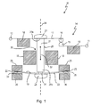
- a first embodiment of a very schematically illustrated temperature-dependent switch 10 is shown, which comprises a first and a second external terminal 11, 12 and a switching mechanism 14, the temperature-dependent establishes or opens an electrically conductive connection between the external terminals 11, 12.
- the rear derailleur 14 comprises a stationary contact part 15 which is electrically conductively connected to the first outer terminal 11 and a movable contact part 16 which cooperates with the stationary contact part 15 and is fastened to a spring part 17 which is electrically conductively connected to the second outer terminal 12 and acts as a closing spring, which presses the movable contact part 16 against the stationary contact part 15.
- the spring member 17 is formed in this simplified embodiment as a leaf spring, which is fixed in the region of the second outer terminal 12 to a schematically illustrated insulator body 18 to which also the first outer terminal 11 and the stationary contact member 15 are fixed.
- the rear derailleur 14 further comprises a bimetallic member 19 and a ram 21 disposed between the bimetal member 19 and the spring member 17.
- the spring member 17 and bimetallic member 19 are disposed at opposite ends 20a and 20b of the ram 21.
- the bimetal part 19 presses the plunger 21 against the spring part 17 when a switching temperature is exceeded, thereby lifting the movable contact part 16 away from the stationary contact part 15.
- the bimetallic part 19 is designed in the embodiment shown as elongated tongue, which are arranged at their opposite narrow sides 22 and 23 each with sufficient for snapping mechanical play between two in the longitudinal direction 24 of the plunger 21 opposing abutments 25, 26.
- the upper abutment 25 are part of the insulator body 18, while the lower abutment 26 are formed as a fastening ring for the bimetal 19.
- the plunger 21 is connected via an upper head 27 and a lower head 28 to train and pressure with the spring member 17 and the bimetal 19, respectively. Between a shaft 29 of the plunger 21 and the lower head 28, a tapered portion 31 is provided, on which the bimetal 17 sits with play. Also, the spring member 17 may be set with play on the plunger 21. The head 27 and the head 28 are widened with respect to the tapered portion 31 and the shaft 29, respectively.
- the shaft 29 of the plunger is guided in a arranged in the insulating member 18 through hole 30 to protect it from tilting and / or jamming.
- the switch 10 is closed.
- the spring part 17 presses the movable contact part 16 on the stationary contact part 15, so that between the two outer terminals 11, 12 of the circuit is closed and the operating current of a device to be protected by the spring member 17 flows.
- the narrow sides 22, 23 of the bimetal part which is in its first geometric configuration, abut against the upper abutments 25 and thus support the closing pressure with which the movable contact part 16 is pressed onto the stationary contact part 15.
- the bimetallic part 17 flips over into its other geometric configuration in such a way that the narrow sides 22, 23 come into abutment with the lower abutment 26, so that the bimetal part 17 engages the plunger 21 in FIG Fig. 1 upwards along the arrow 32 presses. Thereby, the plunger 21 pushes the spring member 17 upward, so that the movable contact member 16 is lifted from the stationary contact member 15 and the circuit is opened.
- Parallel to the bimetallic 19 is formed also designed as an elongated tongue Federschnappteil 33 at the end 20 b of the plunger 21, the opposite narrow sides 34 and 35 are also with play between the abutments 25 and 26.
- the spring snap part also sits with play on the rejuvenated Section 31 of the plunger 21 so that it can exert pressure and tensile forces on the spring member 17 via the plunger.
- the spring snap part 33 can be arranged either between bimetallic 19 and plunger 21, or on the side facing away from the plunger 21 side of the bimetal 19, as shown in the Fig. 1 to 5 is shown.
- the spring snap part 33 further increases the switching dynamics of the rear derailleur 14. In the manner described above, on the one hand, the closing speed is further increased, because the spring snap part 33 also jumps back into its other stable configuration when closing the switch 10 from its one stable configuration, in which the narrow sides 34, 35 rest against the abutments 26, in which the narrow sides are supported on the abutments 25. In this case, the spring snap part 33, like the bimetal part 19, exerts a pulling force on the spring part 17 via the plunger 21.
- the jumping of the spring snap part 33 between its two stable geometric configurations is triggered by the temperature-dependent jumping of the bimetal part 19 between its two geometric configurations.
- the spring snap part 33 also exerts a compressive force on the spring part 17 via the plunger 21, the opening speed with which the movable contact part 16 lifts off from the stationary contact part 15 is increased when the switch 10 is opened by jumping over the bimetal part 19.
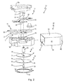
- Fig. 2 shows an exploded view of a specific embodiment of the switch 10 from Fig. 1 ,
- the switch 10 comprises a two-part insulator body 18, which has an upper part 18a and a lower part 18b.
- the first outer terminal 11 is formed as a connection plate 36 which carries the stationary contact part 15.
- the second outer terminal 12 is formed as a terminal plate 37, which is electrically connected to the spring member 17 is connected, which here has a first leg 38 to which the movable contact part 16 is fixed.
- the spring part 17 also has a second leg 39, which runs parallel to the first leg 38 and has a laterally projecting side wing 41, which comes into contact with the second connection plate 37 during assembly.
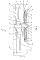
- the insulator body 18 is then inserted into an in Fig. 2 to be recognized flat housing 42 pushed that has a top 43 and a bottom 44, which are connected by narrow sides 45, wherein the housing has on one of its narrow sides 45 an opening 46 and is inserted with this opening 46 on the insulator body 18, such as it in Fig. 3 can be seen.
- the bimetallic part 19 is formed as a bimetallic disc 47 and the spring snap part 33 as a spring snap-action disc 48. Both disks have an edge 51 and 52, respectively, and are inserted into a recess 53, which is arranged on the lower outer side 18c of the lower part 18b, and is outwardly open, in that they bear against circumferential abutments 25a and 25b of the lower part 18b, respectively Switch 10 is closed.
- a ring 54 is inserted, which engages over the edges 51, 52 radially inwardly and forms the abutment 26 on which the bimetallic disc 47 and the spring snap disc 48 are supported with their edges 51 and 52, when they Open switch 10.
- the edges 51 and 52 are guided with a mechanical clearance, so that the bimetallic disc 47 and the spring snap disc As they snap over, they can expand from one another into their other geometric configuration.
- the plunger 21 comprises the shaft 29 with the lower tapered portion 31, on which the bimetallic disc 47 and the spring snap disc 48 are fitted with their respective through hole 55 and 56 with play.
- the plunger 21 passes through the through hole 30 formed in the lower part 18b.
- the head 27 is provided with a bolt 57 and the head 28 with a bolt 58.
- the bolt 57 is seated in an upper blind hole 61 in the shaft 29, the bolt 58 in a lower blind hole 62 in the tapered section 31.die heads 27 and 28 are compared to the bolts 57 and 59 and the shaft 29 widened in diameter.
- the first leg 38 has a through hole 63 with which it is arranged on the bolt 57 with clearance.
- Fig. 5 is in a second embodiment, a switch 10 'and in Fig. 6 in a third embodiment, a switch 10 "shown, each in a representation as in Fig. 1 ,
- the same reference numerals denote identical features with identical properties, so that, due to the basic structure and the principal function to the above description of the Fig. 1 is referenced.
- the switch 10 'off Fig. 5 has only the lower head 28, via which the bimetal 19 and the spring latch member 33 are connected to the plunger 21 so that they along the arrow 32 in Fig. 5 move up and down when the bimetallic 19 and, as a result, the snap spring 33 snaps from its respective one in the other geometric configuration.
- the spring member 17 abuts against the upper end 20a of the plunger 21, so that when the switch 20a is opened by the combined pressure force of the bimetallic member 19 and the spring member 33, it is pushed up very rapidly.
- the spring member 17 is not actively pulled by the plunger 17 down, because the head 27 made Fig. 1 not provided here. Nevertheless, the switch closes 10 'faster than a switch without positive coupling between plunger 21 and bimetallic 19 and spring detent 33, because the plunger 21 is moved so fast down that it opposes the closing movement of the spring member 17 no resistance.
- both the opening speed and the closing speed are increased compared with a switch in which only one bimetallic part 19 is provided which, moreover, is not positively coupled with the tappet 21.
- the assembly is also simpler than with the switch 10 of FIGS Fig. 1 to 4 ,
- the plunger 21 is then connected via the head 28 captive with the bimetal part 19 and the spring snap part 33, and this unit then in Fig. 2 from below into the preassembled insulator body 18, that is inserted into the recess 53 in the lower part 18 b.
- the plunger is thereby passed with its upper end 20a through the through hole 30 and reaches with its upper end 20a in abutment with the first leg 38th
- the bimetal part 19 springs from the in Fig. 6 shown low-temperature configuration in its other geometric configuration. It presses it centrally on the Federschnappteil 33, which is thereby gradually bent so far in its center until it abruptly umschnappt in its other geometrically stable configuration and together with the bimetal 19, the plunger in Fig. 6 abruptly pushes up.
- the spring member 17 abuts against the upper end 20a of the plunger 21, so that it is pushed up very quickly when opening the switch 20a here by the combined pressure of bimetal 19 and spring member 33.
- the spring member 17 is thus not actively pulled by the plunger 17 down, because the head 27 made Fig. 1 is not provided here.
- the switch 10 'opens not only faster than a switch without Federschnappteil 33, it can close faster with appropriate design. This faster closing results because the bimetallic part 19 is moved so fast downwards as a result of the snapping snap spring 33, that it no longer opposes the plunger 21, if this again by the closing movement of the spring member 17 completely down in his in Fig. 6 shown position is moved.
- the insulator body 18 is assembled, so that the two terminal plates 36, 37 and the spring member 17 between the upper part 18a and lower part 18b are clamped.
- the plunger 21 is passed with its upper end 20a through the through hole 30 and reaches with its upper end 20a into abutment with the first leg 38. Then the spring snap part 33 and then the bimetal 19 are inserted into the recess 53.
Landscapes
- Physics & Mathematics (AREA)
- Thermal Sciences (AREA)
- Thermally Actuated Switches (AREA)
Priority Applications (2)
| Application Number | Priority Date | Filing Date | Title |
|---|---|---|---|
| EP17172229.1A EP3229255B1 (fr) | 2013-08-07 | 2014-08-04 | Commutateur thermique |
| PL14179631T PL2843680T3 (pl) | 2013-08-07 | 2014-08-04 | Wyłącznik termiczny |
Applications Claiming Priority (1)
| Application Number | Priority Date | Filing Date | Title |
|---|---|---|---|
| DE102013108504.0A DE102013108504C5 (de) | 2013-08-07 | 2013-08-07 | Temperaturabhängiger Schalter |
Related Child Applications (1)
| Application Number | Title | Priority Date | Filing Date |
|---|---|---|---|
| EP17172229.1A Division EP3229255B1 (fr) | 2013-08-07 | 2014-08-04 | Commutateur thermique |
Publications (3)
| Publication Number | Publication Date |
|---|---|
| EP2843680A2 true EP2843680A2 (fr) | 2015-03-04 |
| EP2843680A3 EP2843680A3 (fr) | 2015-07-08 |
| EP2843680B1 EP2843680B1 (fr) | 2017-05-31 |
Family
ID=51260749
Family Applications (2)
| Application Number | Title | Priority Date | Filing Date |
|---|---|---|---|
| EP14179631.8A Active EP2843680B1 (fr) | 2013-08-07 | 2014-08-04 | Commutateur thermique |
| EP17172229.1A Active EP3229255B1 (fr) | 2013-08-07 | 2014-08-04 | Commutateur thermique |
Family Applications After (1)
| Application Number | Title | Priority Date | Filing Date |
|---|---|---|---|
| EP17172229.1A Active EP3229255B1 (fr) | 2013-08-07 | 2014-08-04 | Commutateur thermique |
Country Status (5)
| Country | Link |
|---|---|
| EP (2) | EP2843680B1 (fr) |
| DE (1) | DE102013108504C5 (fr) |
| DK (1) | DK2843680T3 (fr) |
| ES (1) | ES2637659T3 (fr) |
| PL (1) | PL2843680T3 (fr) |
Cited By (2)
| Publication number | Priority date | Publication date | Assignee | Title |
|---|---|---|---|---|
| CN109064700A (zh) * | 2018-08-27 | 2018-12-21 | 佛山市高明毅力温控器有限公司 | 一种电气火灾报警器 |
| EP4391001A1 (fr) * | 2022-12-21 | 2024-06-26 | Marcel P. Hofsaess | Mécanisme de commutation dépendant de la température et interrupteur dépendant de la température doté d'un tel mécanisme de commutation |
Families Citing this family (1)
| Publication number | Priority date | Publication date | Assignee | Title |
|---|---|---|---|---|
| JP6997685B2 (ja) * | 2018-07-31 | 2022-01-18 | ボーンズ株式会社 | 電流遮断装置、安全回路及び2次電池パック |
Citations (13)
| Publication number | Priority date | Publication date | Assignee | Title |
|---|---|---|---|---|
| US3931603A (en) | 1974-09-19 | 1976-01-06 | Robertshaw Controls Company | Temperature responsive electrical switch construction and method of making the same |
| US3972016A (en) | 1974-06-28 | 1976-07-27 | Therm-O-Disc Incorporated | Thermostat |
| DE2625102A1 (de) | 1976-02-09 | 1977-08-11 | Wirth Gallo & Co | Massen- und kraftmessgeraet |
| DE2644411A1 (de) | 1976-10-01 | 1978-04-06 | Hofsass P | Temperaturwaechter |
| DE3136312A1 (de) | 1981-01-29 | 1982-08-19 | Elmwood Sensors Inc., Cranston, R.I. | Thermostatschalter |
| US4669182A (en) | 1984-01-23 | 1987-06-02 | Therm-O-Disc, Incorporated | Method of gaging a snap disc condition sensor |
| US4908596A (en) | 1989-02-17 | 1990-03-13 | Therm-O-Disc, Incorporated | Thermostat assembly |
| US5059937A (en) | 1990-10-23 | 1991-10-22 | Therm-O-Disc, Incorporated | Switch assembly |
| DE4428226C1 (de) | 1994-08-10 | 1995-10-12 | Thermik Geraetebau Gmbh | Temperaturwächter |
| DE19637706A1 (de) | 1995-09-11 | 1997-03-13 | Elmwood Sensors | Thermoschalter mit Rückstellung |
| DE19816807A1 (de) | 1998-04-16 | 1999-10-28 | Thermik Geraetebau Gmbh | Temperaturabhängiger Schalter |
| US20040066269A1 (en) | 2000-05-30 | 2004-04-08 | Truong Nguyen | Bimetal snap disc thermostat with heaters |
| DE102011016896B3 (de) | 2011-04-13 | 2012-08-23 | Tmc Sensortechnik Gmbh | Temperaturschutzschalter |
Family Cites Families (7)
| Publication number | Priority date | Publication date | Assignee | Title |
|---|---|---|---|---|
| US2309207A (en) * | 1938-10-14 | 1943-01-26 | Honeywell Regulator Co | Electric switch |
| DE2625120C3 (de) * | 1976-06-04 | 1980-04-10 | Peter 7530 Pforzheim Hofsaess | Elektrischer Temperaturschutzschalter |
| CH607300A5 (fr) * | 1976-11-23 | 1978-11-30 | Limitor Ag | |
| DE2917482C2 (de) * | 1979-04-30 | 1982-11-25 | Peter 7530 Pforzheim Hofsäss | Übertemperaturschutzschalter |
| DE19919648C2 (de) * | 1999-04-30 | 2003-03-13 | Marcel Hofsaess | Gerät mit in einer Tasche vorgesehenem temperaturabhängigen Schaltwerk |
| DE102007014237A1 (de) * | 2007-03-16 | 2008-09-18 | Hofsaess, Marcel P. | Temperaturabhängiger Schalter und dafür vorgesehenes Schaltwerk |
| US20130057381A1 (en) * | 2011-09-06 | 2013-03-07 | Honeywell International Inc. | Thermostat and method |
-
2013
- 2013-08-07 DE DE102013108504.0A patent/DE102013108504C5/de active Active
-
2014
- 2014-08-04 EP EP14179631.8A patent/EP2843680B1/fr active Active
- 2014-08-04 PL PL14179631T patent/PL2843680T3/pl unknown
- 2014-08-04 ES ES14179631.8T patent/ES2637659T3/es active Active
- 2014-08-04 EP EP17172229.1A patent/EP3229255B1/fr active Active
- 2014-08-04 DK DK14179631.8T patent/DK2843680T3/en active
Patent Citations (13)
| Publication number | Priority date | Publication date | Assignee | Title |
|---|---|---|---|---|
| US3972016A (en) | 1974-06-28 | 1976-07-27 | Therm-O-Disc Incorporated | Thermostat |
| US3931603A (en) | 1974-09-19 | 1976-01-06 | Robertshaw Controls Company | Temperature responsive electrical switch construction and method of making the same |
| DE2625102A1 (de) | 1976-02-09 | 1977-08-11 | Wirth Gallo & Co | Massen- und kraftmessgeraet |
| DE2644411A1 (de) | 1976-10-01 | 1978-04-06 | Hofsass P | Temperaturwaechter |
| DE3136312A1 (de) | 1981-01-29 | 1982-08-19 | Elmwood Sensors Inc., Cranston, R.I. | Thermostatschalter |
| US4669182A (en) | 1984-01-23 | 1987-06-02 | Therm-O-Disc, Incorporated | Method of gaging a snap disc condition sensor |
| US4908596A (en) | 1989-02-17 | 1990-03-13 | Therm-O-Disc, Incorporated | Thermostat assembly |
| US5059937A (en) | 1990-10-23 | 1991-10-22 | Therm-O-Disc, Incorporated | Switch assembly |
| DE4428226C1 (de) | 1994-08-10 | 1995-10-12 | Thermik Geraetebau Gmbh | Temperaturwächter |
| DE19637706A1 (de) | 1995-09-11 | 1997-03-13 | Elmwood Sensors | Thermoschalter mit Rückstellung |
| DE19816807A1 (de) | 1998-04-16 | 1999-10-28 | Thermik Geraetebau Gmbh | Temperaturabhängiger Schalter |
| US20040066269A1 (en) | 2000-05-30 | 2004-04-08 | Truong Nguyen | Bimetal snap disc thermostat with heaters |
| DE102011016896B3 (de) | 2011-04-13 | 2012-08-23 | Tmc Sensortechnik Gmbh | Temperaturschutzschalter |
Cited By (5)
| Publication number | Priority date | Publication date | Assignee | Title |
|---|---|---|---|---|
| CN109064700A (zh) * | 2018-08-27 | 2018-12-21 | 佛山市高明毅力温控器有限公司 | 一种电气火灾报警器 |
| CN109064700B (zh) * | 2018-08-27 | 2024-04-02 | 佛山市高明毅力温控器有限公司 | 一种电气火灾报警器 |
| EP4391001A1 (fr) * | 2022-12-21 | 2024-06-26 | Marcel P. Hofsaess | Mécanisme de commutation dépendant de la température et interrupteur dépendant de la température doté d'un tel mécanisme de commutation |
| EP4539083A1 (fr) * | 2022-12-21 | 2025-04-16 | Marcel P. Hofsaess | Mécanisme de commutation dépendant de la température et interrupteur dépendant de la température doté d'un tel mécanisme de commutation |
| US12586745B2 (en) | 2022-12-21 | 2026-03-24 | Marcel P. HOFSAESS | Temperature-dependent switching mechanism and temperature-dependent switch |
Also Published As
| Publication number | Publication date |
|---|---|
| PL2843680T3 (pl) | 2017-10-31 |
| DK2843680T3 (en) | 2017-09-04 |
| DE102013108504A1 (de) | 2015-02-12 |
| DE102013108504B4 (de) | 2015-02-19 |
| EP2843680B1 (fr) | 2017-05-31 |
| EP3229255A1 (fr) | 2017-10-11 |
| EP2843680A3 (fr) | 2015-07-08 |
| DE102013108504C5 (de) | 2018-11-15 |
| ES2637659T3 (es) | 2017-10-16 |
| EP3229255B1 (fr) | 2023-03-22 |
Similar Documents
| Publication | Publication Date | Title |
|---|---|---|
| DE102011101862B4 (de) | Temperaturabhängiger Schalter mit Stromübertragungsglied | |
| DE102007063650B4 (de) | Temperaturabhängiger Schalter mit Selbsthaltefunktion | |
| EP3796359B1 (fr) | Commutateur dépendant de la température | |
| EP2867910B1 (fr) | Circuit protecteur thermique | |
| DE102011016896C5 (de) | Temperaturschutzschalter | |
| DE102013101392A1 (de) | Temperaturabhängiger Schalter | |
| EP2958125B1 (fr) | Commutateur thermodépendant doté de bague d'espacement | |
| DE2917557C2 (de) | Wärmeschutzschalter | |
| EP0951040B2 (fr) | Interrupteur à commande thermique | |
| EP0828273B1 (fr) | Interrupteur avec un élément de sécurité | |
| EP2843680B1 (fr) | Commutateur thermique | |
| EP3736845B1 (fr) | Commutateur dépendant de la température | |
| EP0938116B1 (fr) | Interrupteur | |
| EP0201002B1 (fr) | Elément interrupteur à commande thermique, en particulier thermostat ou limiteur de température | |
| DE102013022331B4 (de) | Temperaturabhängiger Schalter | |
| DE2511214C2 (de) | Temperaturregeleinrichtung für elektrische Geräte | |
| DE102017112281A1 (de) | Schutz-Vorrichtung sowie Anordnung mit einer solchen Schutz-Vorrichtung, einem elektrischen Motor und einer Stromversorgung | |
| DE69837032T2 (de) | Magnetothermische Steuervorrichtung und mit einer solchen Vorrichtung ausgerüsteter Schutzschalter | |
| EP0162940A1 (fr) | Interrupteur de protection contre les surchages | |
| DE102011104984B4 (de) | Temperaturabhängiger Schalter mit Heizwiderstand auf Trägerplatte |
Legal Events
| Date | Code | Title | Description |
|---|---|---|---|
| 17P | Request for examination filed |
Effective date: 20140804 |
|
| AK | Designated contracting states |
Kind code of ref document: A2 Designated state(s): AL AT BE BG CH CY CZ DE DK EE ES FI FR GB GR HR HU IE IS IT LI LT LU LV MC MK MT NL NO PL PT RO RS SE SI SK SM TR |
|
| AX | Request for extension of the european patent |
Extension state: BA ME |
|
| PUAI | Public reference made under article 153(3) epc to a published international application that has entered the european phase |
Free format text: ORIGINAL CODE: 0009012 |
|
| PUAL | Search report despatched |
Free format text: ORIGINAL CODE: 0009013 |
|
| AK | Designated contracting states |
Kind code of ref document: A3 Designated state(s): AL AT BE BG CH CY CZ DE DK EE ES FI FR GB GR HR HU IE IS IT LI LT LU LV MC MK MT NL NO PL PT RO RS SE SI SK SM TR |
|
| AX | Request for extension of the european patent |
Extension state: BA ME |
|
| RIC1 | Information provided on ipc code assigned before grant |
Ipc: H01H 1/26 20060101ALN20150603BHEP Ipc: H01H 37/54 20060101AFI20150603BHEP |
|
| R17P | Request for examination filed (corrected) |
Effective date: 20151215 |
|
| RBV | Designated contracting states (corrected) |
Designated state(s): AL AT BE BG CH CY CZ DE DK EE ES FI FR GB GR HR HU IE IS IT LI LT LU LV MC MK MT NL NO PL PT RO RS SE SI SK SM TR |
|
| 17Q | First examination report despatched |
Effective date: 20160614 |
|
| GRAP | Despatch of communication of intention to grant a patent |
Free format text: ORIGINAL CODE: EPIDOSNIGR1 |
|
| STAA | Information on the status of an ep patent application or granted ep patent |
Free format text: STATUS: GRANT OF PATENT IS INTENDED |
|
| RIC1 | Information provided on ipc code assigned before grant |
Ipc: H01H 1/26 20060101ALN20161121BHEP Ipc: H01H 37/54 20060101AFI20161121BHEP |
|
| RIC1 | Information provided on ipc code assigned before grant |
Ipc: H01H 37/54 20060101AFI20161207BHEP Ipc: H01H 1/26 20060101ALN20161207BHEP |
|
| INTG | Intention to grant announced |
Effective date: 20161222 |
|
| GRAS | Grant fee paid |
Free format text: ORIGINAL CODE: EPIDOSNIGR3 |
|
| GRAA | (expected) grant |
Free format text: ORIGINAL CODE: 0009210 |
|
| STAA | Information on the status of an ep patent application or granted ep patent |
Free format text: STATUS: THE PATENT HAS BEEN GRANTED |
|
| AK | Designated contracting states |
Kind code of ref document: B1 Designated state(s): AL AT BE BG CH CY CZ DE DK EE ES FI FR GB GR HR HU IE IS IT LI LT LU LV MC MK MT NL NO PL PT RO RS SE SI SK SM TR |
|
| REG | Reference to a national code |
Ref country code: GB Ref legal event code: FG4D Free format text: NOT ENGLISH Ref country code: CH Ref legal event code: EP |
|
| REG | Reference to a national code |
Ref country code: AT Ref legal event code: REF Ref document number: 898144 Country of ref document: AT Kind code of ref document: T Effective date: 20170615 |
|
| REG | Reference to a national code |
Ref country code: IE Ref legal event code: FG4D Free format text: LANGUAGE OF EP DOCUMENT: GERMAN |
|
| REG | Reference to a national code |
Ref country code: DE Ref legal event code: R096 Ref document number: 502014003985 Country of ref document: DE |
|
| REG | Reference to a national code |
Ref country code: CH Ref legal event code: NV Representative=s name: RENTSCH PARTNER AG, CH |
|
| REG | Reference to a national code |
Ref country code: FR Ref legal event code: PLFP Year of fee payment: 4 |
|
| REG | Reference to a national code |
Ref country code: DK Ref legal event code: T3 Effective date: 20170901 |
|
| REG | Reference to a national code |
Ref country code: NL Ref legal event code: FP |
|
| REG | Reference to a national code |
Ref country code: SE Ref legal event code: TRGR |
|
| REG | Reference to a national code |
Ref country code: CH Ref legal event code: PCAR Free format text: NEW ADDRESS: BELLERIVESTRASSE 203 POSTFACH, 8034 ZUERICH (CH) |
|
| REG | Reference to a national code |
Ref country code: LT Ref legal event code: MG4D |
|
| REG | Reference to a national code |
Ref country code: ES Ref legal event code: FG2A Ref document number: 2637659 Country of ref document: ES Kind code of ref document: T3 Effective date: 20171016 |
|
| PG25 | Lapsed in a contracting state [announced via postgrant information from national office to epo] |
Ref country code: GR Free format text: LAPSE BECAUSE OF FAILURE TO SUBMIT A TRANSLATION OF THE DESCRIPTION OR TO PAY THE FEE WITHIN THE PRESCRIBED TIME-LIMIT Effective date: 20170901 Ref country code: NO Free format text: LAPSE BECAUSE OF FAILURE TO SUBMIT A TRANSLATION OF THE DESCRIPTION OR TO PAY THE FEE WITHIN THE PRESCRIBED TIME-LIMIT Effective date: 20170831 Ref country code: HR Free format text: LAPSE BECAUSE OF FAILURE TO SUBMIT A TRANSLATION OF THE DESCRIPTION OR TO PAY THE FEE WITHIN THE PRESCRIBED TIME-LIMIT Effective date: 20170531 Ref country code: FI Free format text: LAPSE BECAUSE OF FAILURE TO SUBMIT A TRANSLATION OF THE DESCRIPTION OR TO PAY THE FEE WITHIN THE PRESCRIBED TIME-LIMIT Effective date: 20170531 Ref country code: LT Free format text: LAPSE BECAUSE OF FAILURE TO SUBMIT A TRANSLATION OF THE DESCRIPTION OR TO PAY THE FEE WITHIN THE PRESCRIBED TIME-LIMIT Effective date: 20170531 |
|
| PGFP | Annual fee paid to national office [announced via postgrant information from national office to epo] |
Ref country code: FR Payment date: 20170830 Year of fee payment: 4 Ref country code: ES Payment date: 20170928 Year of fee payment: 4 Ref country code: CH Payment date: 20170921 Year of fee payment: 4 |
|
| PG25 | Lapsed in a contracting state [announced via postgrant information from national office to epo] |
Ref country code: LV Free format text: LAPSE BECAUSE OF FAILURE TO SUBMIT A TRANSLATION OF THE DESCRIPTION OR TO PAY THE FEE WITHIN THE PRESCRIBED TIME-LIMIT Effective date: 20170531 Ref country code: RS Free format text: LAPSE BECAUSE OF FAILURE TO SUBMIT A TRANSLATION OF THE DESCRIPTION OR TO PAY THE FEE WITHIN THE PRESCRIBED TIME-LIMIT Effective date: 20170531 Ref country code: IS Free format text: LAPSE BECAUSE OF FAILURE TO SUBMIT A TRANSLATION OF THE DESCRIPTION OR TO PAY THE FEE WITHIN THE PRESCRIBED TIME-LIMIT Effective date: 20170930 Ref country code: BG Free format text: LAPSE BECAUSE OF FAILURE TO SUBMIT A TRANSLATION OF THE DESCRIPTION OR TO PAY THE FEE WITHIN THE PRESCRIBED TIME-LIMIT Effective date: 20170831 |
|
| PGFP | Annual fee paid to national office [announced via postgrant information from national office to epo] |
Ref country code: DK Payment date: 20170830 Year of fee payment: 4 Ref country code: PL Payment date: 20170801 Year of fee payment: 4 |
|
| PG25 | Lapsed in a contracting state [announced via postgrant information from national office to epo] |
Ref country code: RO Free format text: LAPSE BECAUSE OF FAILURE TO SUBMIT A TRANSLATION OF THE DESCRIPTION OR TO PAY THE FEE WITHIN THE PRESCRIBED TIME-LIMIT Effective date: 20170531 Ref country code: SK Free format text: LAPSE BECAUSE OF FAILURE TO SUBMIT A TRANSLATION OF THE DESCRIPTION OR TO PAY THE FEE WITHIN THE PRESCRIBED TIME-LIMIT Effective date: 20170531 Ref country code: EE Free format text: LAPSE BECAUSE OF FAILURE TO SUBMIT A TRANSLATION OF THE DESCRIPTION OR TO PAY THE FEE WITHIN THE PRESCRIBED TIME-LIMIT Effective date: 20170531 Ref country code: CZ Free format text: LAPSE BECAUSE OF FAILURE TO SUBMIT A TRANSLATION OF THE DESCRIPTION OR TO PAY THE FEE WITHIN THE PRESCRIBED TIME-LIMIT Effective date: 20170531 |
|
| PG25 | Lapsed in a contracting state [announced via postgrant information from national office to epo] |
Ref country code: SM Free format text: LAPSE BECAUSE OF FAILURE TO SUBMIT A TRANSLATION OF THE DESCRIPTION OR TO PAY THE FEE WITHIN THE PRESCRIBED TIME-LIMIT Effective date: 20170531 |
|
| REG | Reference to a national code |
Ref country code: DE Ref legal event code: R097 Ref document number: 502014003985 Country of ref document: DE |
|
| PG25 | Lapsed in a contracting state [announced via postgrant information from national office to epo] |
Ref country code: MC Free format text: LAPSE BECAUSE OF FAILURE TO SUBMIT A TRANSLATION OF THE DESCRIPTION OR TO PAY THE FEE WITHIN THE PRESCRIBED TIME-LIMIT Effective date: 20170531 |
|
| PLBE | No opposition filed within time limit |
Free format text: ORIGINAL CODE: 0009261 |
|
| STAA | Information on the status of an ep patent application or granted ep patent |
Free format text: STATUS: NO OPPOSITION FILED WITHIN TIME LIMIT |
|
| REG | Reference to a national code |
Ref country code: BE Ref legal event code: MM Effective date: 20170831 |
|
| 26N | No opposition filed |
Effective date: 20180301 |
|
| REG | Reference to a national code |
Ref country code: IE Ref legal event code: MM4A |
|
| PG25 | Lapsed in a contracting state [announced via postgrant information from national office to epo] |
Ref country code: SI Free format text: LAPSE BECAUSE OF FAILURE TO SUBMIT A TRANSLATION OF THE DESCRIPTION OR TO PAY THE FEE WITHIN THE PRESCRIBED TIME-LIMIT Effective date: 20170531 |
|
| PG25 | Lapsed in a contracting state [announced via postgrant information from national office to epo] |
Ref country code: LU Free format text: LAPSE BECAUSE OF NON-PAYMENT OF DUE FEES Effective date: 20170804 |
|
| PG25 | Lapsed in a contracting state [announced via postgrant information from national office to epo] |
Ref country code: IE Free format text: LAPSE BECAUSE OF NON-PAYMENT OF DUE FEES Effective date: 20170804 |
|
| PG25 | Lapsed in a contracting state [announced via postgrant information from national office to epo] |
Ref country code: BE Free format text: LAPSE BECAUSE OF NON-PAYMENT OF DUE FEES Effective date: 20170831 |
|
| PG25 | Lapsed in a contracting state [announced via postgrant information from national office to epo] |
Ref country code: MT Free format text: LAPSE BECAUSE OF FAILURE TO SUBMIT A TRANSLATION OF THE DESCRIPTION OR TO PAY THE FEE WITHIN THE PRESCRIBED TIME-LIMIT Effective date: 20170531 |
|
| REG | Reference to a national code |
Ref country code: DK Ref legal event code: EBP Effective date: 20180831 |
|
| REG | Reference to a national code |
Ref country code: CH Ref legal event code: PL |
|
| GBPC | Gb: european patent ceased through non-payment of renewal fee |
Effective date: 20180804 |
|
| PG25 | Lapsed in a contracting state [announced via postgrant information from national office to epo] |
Ref country code: LI Free format text: LAPSE BECAUSE OF NON-PAYMENT OF DUE FEES Effective date: 20180831 Ref country code: CH Free format text: LAPSE BECAUSE OF NON-PAYMENT OF DUE FEES Effective date: 20180831 |
|
| PG25 | Lapsed in a contracting state [announced via postgrant information from national office to epo] |
Ref country code: HU Free format text: LAPSE BECAUSE OF FAILURE TO SUBMIT A TRANSLATION OF THE DESCRIPTION OR TO PAY THE FEE WITHIN THE PRESCRIBED TIME-LIMIT; INVALID AB INITIO Effective date: 20140804 |
|
| PG25 | Lapsed in a contracting state [announced via postgrant information from national office to epo] |
Ref country code: DK Free format text: LAPSE BECAUSE OF NON-PAYMENT OF DUE FEES Effective date: 20180831 |
|
| PG25 | Lapsed in a contracting state [announced via postgrant information from national office to epo] |
Ref country code: FR Free format text: LAPSE BECAUSE OF NON-PAYMENT OF DUE FEES Effective date: 20180831 |
|
| REG | Reference to a national code |
Ref country code: ES Ref legal event code: FD2A Effective date: 20190918 |
|
| PG25 | Lapsed in a contracting state [announced via postgrant information from national office to epo] |
Ref country code: ES Free format text: LAPSE BECAUSE OF NON-PAYMENT OF DUE FEES Effective date: 20180805 Ref country code: CY Free format text: LAPSE BECAUSE OF FAILURE TO SUBMIT A TRANSLATION OF THE DESCRIPTION OR TO PAY THE FEE WITHIN THE PRESCRIBED TIME-LIMIT Effective date: 20170531 Ref country code: GB Free format text: LAPSE BECAUSE OF NON-PAYMENT OF DUE FEES Effective date: 20180804 |
|
| PG25 | Lapsed in a contracting state [announced via postgrant information from national office to epo] |
Ref country code: MK Free format text: LAPSE BECAUSE OF FAILURE TO SUBMIT A TRANSLATION OF THE DESCRIPTION OR TO PAY THE FEE WITHIN THE PRESCRIBED TIME-LIMIT Effective date: 20170531 |
|
| PG25 | Lapsed in a contracting state [announced via postgrant information from national office to epo] |
Ref country code: PL Free format text: LAPSE BECAUSE OF NON-PAYMENT OF DUE FEES Effective date: 20180804 |
|
| PG25 | Lapsed in a contracting state [announced via postgrant information from national office to epo] |
Ref country code: TR Free format text: LAPSE BECAUSE OF FAILURE TO SUBMIT A TRANSLATION OF THE DESCRIPTION OR TO PAY THE FEE WITHIN THE PRESCRIBED TIME-LIMIT Effective date: 20170531 |
|
| PG25 | Lapsed in a contracting state [announced via postgrant information from national office to epo] |
Ref country code: PT Free format text: LAPSE BECAUSE OF FAILURE TO SUBMIT A TRANSLATION OF THE DESCRIPTION OR TO PAY THE FEE WITHIN THE PRESCRIBED TIME-LIMIT Effective date: 20170531 |
|
| PG25 | Lapsed in a contracting state [announced via postgrant information from national office to epo] |
Ref country code: AL Free format text: LAPSE BECAUSE OF FAILURE TO SUBMIT A TRANSLATION OF THE DESCRIPTION OR TO PAY THE FEE WITHIN THE PRESCRIBED TIME-LIMIT Effective date: 20170531 |
|
| REG | Reference to a national code |
Ref country code: AT Ref legal event code: MM01 Ref document number: 898144 Country of ref document: AT Kind code of ref document: T Effective date: 20190804 |
|
| PG25 | Lapsed in a contracting state [announced via postgrant information from national office to epo] |
Ref country code: AT Free format text: LAPSE BECAUSE OF NON-PAYMENT OF DUE FEES Effective date: 20190804 |
|
| PGFP | Annual fee paid to national office [announced via postgrant information from national office to epo] |
Ref country code: SE Payment date: 20200826 Year of fee payment: 7 |
|
| PGFP | Annual fee paid to national office [announced via postgrant information from national office to epo] |
Ref country code: NL Payment date: 20210819 Year of fee payment: 8 |
|
| REG | Reference to a national code |
Ref country code: SE Ref legal event code: EUG |
|
| PG25 | Lapsed in a contracting state [announced via postgrant information from national office to epo] |
Ref country code: SE Free format text: LAPSE BECAUSE OF NON-PAYMENT OF DUE FEES Effective date: 20210805 |
|
| REG | Reference to a national code |
Ref country code: NL Ref legal event code: MM Effective date: 20220901 |
|
| P01 | Opt-out of the competence of the unified patent court (upc) registered |
Effective date: 20230522 |
|
| PG25 | Lapsed in a contracting state [announced via postgrant information from national office to epo] |
Ref country code: NL Free format text: LAPSE BECAUSE OF NON-PAYMENT OF DUE FEES Effective date: 20220901 |
|
| PGFP | Annual fee paid to national office [announced via postgrant information from national office to epo] |
Ref country code: DE Payment date: 20250826 Year of fee payment: 12 |
|
| PGFP | Annual fee paid to national office [announced via postgrant information from national office to epo] |
Ref country code: IT Payment date: 20250825 Year of fee payment: 12 |