EP2848950A1 - Installation d'antenne radio avec la surveillance d'une propriété électrique d'un câble et une partie de montée à coupler une unité de mesure de résistance. - Google Patents
Installation d'antenne radio avec la surveillance d'une propriété électrique d'un câble et une partie de montée à coupler une unité de mesure de résistance. Download PDFInfo
- Publication number
- EP2848950A1 EP2848950A1 EP14003004.0A EP14003004A EP2848950A1 EP 2848950 A1 EP2848950 A1 EP 2848950A1 EP 14003004 A EP14003004 A EP 14003004A EP 2848950 A1 EP2848950 A1 EP 2848950A1
- Authority
- EP
- European Patent Office
- Prior art keywords
- contact element
- transmitting antenna
- antenna system
- measuring device
- transport path
- Prior art date
- Legal status (The legal status is an assumption and is not a legal conclusion. Google has not performed a legal analysis and makes no representation as to the accuracy of the status listed.)
- Withdrawn
Links
- 230000008878 coupling Effects 0.000 title claims description 43
- 238000010168 coupling process Methods 0.000 title claims description 43
- 238000005859 coupling reaction Methods 0.000 title claims description 43
- 238000009434 installation Methods 0.000 title claims description 17
- 230000005540 biological transmission Effects 0.000 claims abstract description 43
- 238000005259 measurement Methods 0.000 claims abstract description 28
- 238000012544 monitoring process Methods 0.000 claims abstract description 26
- 239000003990 capacitor Substances 0.000 claims description 22
- 238000009413 insulation Methods 0.000 claims description 14
- 238000002347 injection Methods 0.000 claims description 9
- 239000007924 injection Substances 0.000 claims description 9
- 230000007704 transition Effects 0.000 claims description 9
- 230000006978 adaptation Effects 0.000 claims description 7
- 238000000034 method Methods 0.000 claims description 7
- 230000007935 neutral effect Effects 0.000 claims description 3
- 230000036962 time dependent Effects 0.000 claims description 2
- 238000012546 transfer Methods 0.000 claims description 2
- 230000008901 benefit Effects 0.000 description 9
- 230000006378 damage Effects 0.000 description 6
- 238000013461 design Methods 0.000 description 6
- 238000010586 diagram Methods 0.000 description 6
- 230000015572 biosynthetic process Effects 0.000 description 2
- 239000000919 ceramic Substances 0.000 description 2
- 230000008859 change Effects 0.000 description 2
- 230000001066 destructive effect Effects 0.000 description 2
- 238000011161 development Methods 0.000 description 2
- 230000018109 developmental process Effects 0.000 description 2
- 230000000694 effects Effects 0.000 description 2
- 238000005516 engineering process Methods 0.000 description 2
- 238000011156 evaluation Methods 0.000 description 2
- 238000000926 separation method Methods 0.000 description 2
- 238000012360 testing method Methods 0.000 description 2
- 230000001960 triggered effect Effects 0.000 description 2
- 230000003993 interaction Effects 0.000 description 1
- JEIPFZHSYJVQDO-UHFFFAOYSA-N iron(III) oxide Inorganic materials O=[Fe]O[Fe]=O JEIPFZHSYJVQDO-UHFFFAOYSA-N 0.000 description 1
- 238000010409 ironing Methods 0.000 description 1
- 238000006386 neutralization reaction Methods 0.000 description 1
- 230000037361 pathway Effects 0.000 description 1
- 230000009467 reduction Effects 0.000 description 1
- 230000008439 repair process Effects 0.000 description 1
- 238000001228 spectrum Methods 0.000 description 1
- 230000002269 spontaneous effect Effects 0.000 description 1
Images


Classifications
-
- H—ELECTRICITY
- H04—ELECTRIC COMMUNICATION TECHNIQUE
- H04B—TRANSMISSION
- H04B17/00—Monitoring; Testing
- H04B17/10—Monitoring; Testing of transmitters
- H04B17/101—Monitoring; Testing of transmitters for measurement of specific parameters of the transmitter or components thereof
- H04B17/104—Monitoring; Testing of transmitters for measurement of specific parameters of the transmitter or components thereof of other parameters, e.g. DC offset, delay or propagation times
-
- G—PHYSICS
- G01—MEASURING; TESTING
- G01R—MEASURING ELECTRIC VARIABLES; MEASURING MAGNETIC VARIABLES
- G01R31/00—Arrangements for testing electric properties; Arrangements for locating electric faults; Arrangements for electrical testing characterised by what is being tested not provided for elsewhere
- G01R31/50—Testing of electric apparatus, lines, cables or components for short-circuits, continuity, leakage current or incorrect line connections
- G01R31/58—Testing of lines, cables or conductors
Definitions
- the invention relates to a transmitting antenna system with a transmission power of at least 2 kW with a monitoring of an electrical line characteristic of the transmitting antenna system. Furthermore, a built-in component with at least one coupling of a resistance-measuring device direction into a power transport path of such a transmitting antenna system is proposed.
- Transmitting antenna systems with a transmission power of at least 2 kW are used for example in terrestrial broadcasting technology.
- Examples include transmitting antenna systems, which are used for the broadcasting of radio programs in the frequency ranges FM, DAB and partly also the DVB-T.
- Transmitting antenna systems of these examples have at least one transmitting antenna, in most cases also a plurality of transmitting antennas.
- the transmission antennas are often housed in tall structures, such as in radio towers.
- the invention is based on the object of increasing the safety of the transmitting antenna system, in particular with regard to imminent damage caused by sources of fire.
- the object is with a transmitting antenna system with a transmission power of at least 2 kW with a monitoring of an electrical line property of the transmitting antenna system according to claim 1 and with a built-in part with at least one coupling of a resistance measuring device in a power transport path of the transmitting antenna system solved with a transmission power of at least 2 kW according to claim 13. Furthermore, the object is achieved with a method for monitoring an electrical line characteristic of a transmitting antenna system with a transmission power of at least 2 kW according to claim 19. Further advantageous embodiments and developments will become apparent from the following description.
- One or more features of the claims, description, and figures may be combined with one or more other features of the disclosure to provide additional further aspects of the invention.
- one or more features of the independent claims may be replaced by one or more other features of the description and / or figures.
- the proposed claims are preferably to be construed as merely a draft to formulate the subject matter without, however, limiting it.
- the transmitting antenna system has at least one power transport path for supplying power to at least one first transmitting antenna and at least one resistance measuring device for determining an ohmic resistance for monitoring the transmitting antenna system.
- the resistance measuring device comprises at least one DC voltage source for acting on at least the portion of the power transport path with a DC measuring voltage. Furthermore, the resistance measuring device has at least one measuring device for determining the resistance of the section which is subjected to the measuring direct voltage.
- the proposed monitoring at transmit power up to 50 kW, preferably from preferably 2 kW to 50 kW can be used operationally.
- a measuring device for determining the resistance may be an ohmmeter, but it may also be additionally or alternatively provided, for example, that a measuring device is provided which provides an indirect determination of a resistance.
- a redundancy measurement may be provided, for example for adjustment and / or for cross-checking Determination of a determination of an electrical current and / or an electrical voltage to be provided.
- the resistance measuring device is arranged in an electrical feed line region of the power transport path.
- the power line section of the power transport path designates a portion of the transmitting antenna system, which is preferably formed as an RF cable or as an RF cable bundle leading to the first transmitting antenna.
- the resistance measuring device is arranged on or in an HF cable or on or in a casing section of the power transport path.
- An advantage of an arrangement of the resistance measuring device on or in an RF cable or on a piping section of the power transport path is, for example, that a cost-effective attachment of the resistance measuring device is possible due to its direct arrangement with the already existing infrastructure of the transmitting antenna system while at the same time being efficient works and can be flexibly positioned.
- a resistance measuring device may be arranged to be displaceable.
- a further embodiment provides, for example, that the resistance measuring device is not permanently installed. Rather, according to one embodiment, these can be arranged completely or at least partially only temporarily or arranged in the power transport path. Thus, for example, by means of a transportable checking device, a check of the power transport path can take place or a check can be made of the permanently installed monitoring of the power transport path according to the system described here.
- the resistance measuring device is arranged at a feed line beginning.
- An arrangement of the resistance measuring device at a feed line beginning in particular has the advantage of being able to enable a complete monitoring of the infrastructure located beyond the feed line beginning to change the resistance.
- a complete monitoring of the power transport path and the transmitting antenna against change in resistance allows.
- the resistance measuring device is arranged in a pluggable switching field of the feed line beginning.
- An introduction of the resistance measuring device in an equipable switching field of the feed line start has the advantage that the flexible assembly of the transmitting antenna system is possible.
- introducing the resistance measuring device into an equipable switching field of the feed line start has the advantage that already provided components provided for introduction into the switching field can be modified and used with the integrated resistance measuring device such that the existing infrastructure can otherwise be used largely unchanged ,
- each of the half antennas may use a dedicated resistance measuring device and / or a dedicated DC feed element.
- the resistance measuring device is completely or partially installed in a U-shaped plug, which has at least one GleichstromeinspeIseglied.
- the resistance measuring device has a direct current injection element.
- the power transmission path of the transmitting antenna system which is provided during operation for the transport of high-frequency power, be subjected to a direct current.
- the direct current feeding element has a first contact element and a second contact element. It may further be provided that the first contact element and the second contact element are capacitively coupled, for example by means of at least one capacitor.
- the capacitive coupling causes the RF power to be transported to continue to pass between the transmitter and the power transport path, but the path for a DC power is disabled due to the capacitive coupling.
- provision can be made, for example, for a second connecting line leading from a first connecting line of the first contact element to the second contact element to lead to a third contact element.
- the second connecting line is starting from one side of the first connecting line, which faces the power transport path side of the capacitor. This creates a possibility of connecting the power transport path to one end of the second connection line, whereas a connection of one end of the second connection line to the transmission system is prevented via a direct current through the capacitive coupling of the first contact element.
- the second connecting line has at least one coupling element of the DC infeed element for connecting the second contact element to the third contact element.
- the coupling member as ⁇ / 4-stub adjustment to the transmitting antenna or as an LC parallel resonant circuit is formed.
- the coupling member is designed as a throttle.
- a coupling member which is designed as a ⁇ / 4-stub adaptation, as an LC parallel oscillating circuit or as a choke, inter alia, takes place by means of destructive interference leading to the power transport path AC voltage attenuation in the direction of the measuring device and / or the DC voltage source, so that they are separated from the AC voltage-conducting components of the transmitting antenna system.
- the design of the coupling element at a bandwidth of a frequency range emitted by the transmitting antenna is carried out, for example, in such a way that the coupling element filters a frequency approximately in the middle of the frequency range.
- ⁇ c / f
- c the speed of light
- f the above-mentioned frequency.
- a return loss value of> 21 dB and a negligibly small transmission loss were demonstrated in a field test, so that the intended function of the DC infeed was ensured in combination with an insulation measuring device.
- the transmission parameters of the emitted signals were not demonstrably influenced, as a result of which the functionality of the described experimental setup is proven.
- the second connecting line has a transition capacitor of the DC feed element arranged between the coupling element and the third contact element.
- an RF neutral space of the DC feed member is arranged, which preferably has a gas discharge surge arrester.
- the resistance measuring device has a built-in, preferably exchangeable and / or pluggable, built-in component which contains at least the direct-current injection element.
- the insulation measuring device preferably has the DC voltage source and the measuring device for determining the resistance.
- the connector of the dc feed member with the insulation measuring means forms, for example, the resistance measuring means.
- a combination of at least one DC power source and at least one measuring device is arranged on the third plug socket.
- the resistance measuring device is formed in which more than one DC power source and more than one measuring device are arranged on the third plug socket.
- Embodiments are also possible in which the DC feed element, the DC source and / or the measuring device are arranged in a compact component.
- a connection with the first socket, with the second socket and / or the third socket can be revisibly solvable, which in particular has the advantage that the resistance measuring device or components of the resistance measuring device are interchangeable.
- the DC feed member is provided as a compact component, and that the DC feed member is present as an exchangeable built-in component.
- a connection of the third socket to the DC power source and / or the measuring device or a connection of the third socket with the insulation measuring device is designed as non-destructive releasable, for example, as a welded connection.
- a DC measurement voltage with a value between 500 V and 1500 V can be provided.
- a DC measurement voltage with a value between 750 and 1250 V can be provided.
- different measured DC voltages can be used, which are preferably within the specified range.
- the transmitting antenna system is a radio antenna system.
- Another aspect of the invention which can be used depending as well as independently of the transmitting antenna system described above, relates to a built-in part.
- the resistance measuring device preferably has an insulation measuring device.
- a built-in part may be provided, whose first contact element and second contact element are capacitively coupled by means of at least one capacitor of the DC infeed element.
- the installation part it can be provided, for example, that starting from a first connection line of the DC infeed element between the first contact element and the second contact element, preferably power transmission side of the capacitor, a second connecting line of the DC infeed member leading to the third contact element is arranged.
- a coupling element may be provided, which is provided as part of the second connection line.
- the coupling element is preferably designed as a ⁇ / 4 stub line adaptation to the transmitting antenna and / or as an L-C parallel resonant circuit.
- the second connecting line has a transition capacitor arranged between the coupling element and the third contact element and that an HF-neutral space of the DC infeed element is arranged between the transition capacitor and the third contact element, which preferably has a surge arrester.
- the third contact element is a two-pole socket with a first pole and a second pole, one of the two poles being a grounding pole.
- a resistance measuring device is arranged exchangeably on the installation part.
- Another aspect of the invention which can be applied depending on how independent of the transmitting antenna equipment described above, relates to a method for Monitoring an electrical line characteristic of a transmitting antenna system with a transmission power of at least 2 kW.
- the transmitting antenna system has at least one power transport path and at least one first transmitting antenna.
- At least one section of the power transport path is subjected to a DC measurement voltage and an ohmic resistance determination of at least the section of the power transport path is made.
- the ohmic resistance determination is time-dependent.
- an alarm signal is output when falling below a set threshold value of the ohmic resistance, preferably when falling below an ohmic resistance value between 100 kOhm and 500 kOhm, particularly preferably falls below an ohmic resistance value between 150 kOhm and 250 kOhm.
- the values mentioned here are low enough to avoid any false alarms due to weather-related lowering of the resistance values, for example due to high air humidity and / or salty air.
- the ohmic resistance determination is carried out with a controlled resistance determination in a continuous manner or at predetermined times.
- a use of a transmitting antenna installation for the monitored operation of a telecommunication system with continuous or regularly recurring insulation measurement can be provided by applying at least a portion of the power transport path of the transmitting antenna installation with a DC measuring voltage and an ohmic resistance determination of the section of the power transport path.
- measurements are made at equidistant intervals.
- An active control is not necessarily necessary for this, but a control can take place according to a predetermined schedule.
- measurements are taken at an interval of N hours between an ith measurement and an (i + 1) th measurement, where i is a positive natural number used as a running index.
- the number N here can be a positive decimal number between 2 and 10, preferably between 4 and 8, particularly preferably between 5 and 7.
- the measurement result can be displayed directly on site, for example.
- the measurement result is transmitted, for example via a bus system.
- a remote transmission may be provided, which allows monitoring far away from the transmitter.
- This may be, for example, a central monitoring center capable of monitoring a plurality of transmitters, towers and towers at different locations.
- the monitoring is computer controlled.
- a measurement can not only be monitored but also triggered by computer control.
- the measurement results are stored and can be evaluated automatically, for example, be evaluated statistically. For example, a repair may be triggered by this, in particular a foresighted check before major damage can occur.
- a radio tower may have a plurality of such monitors distributed along the power transport path, preferably one behind the other at greater distances from each other along the path. This not only allows, for example, the entire measurement of the power transport path. Rather, it is possible by respective Measurement to locate one or more fault locations better along the power transport path. Thus, for example, a deviation can be detected via a comparison with a reference measurement. If the measurement starts with a monitoring that is closest to the transmitting antenna, but there are no or only slight deviations from the reference measurement, it can then be determined by the measurement at the next monitoring, further away from the transmitting antenna, whether set a deviation outside a tolerance. Thus, the test can be carried out more and more, until finally there is a deviation for the first time out of tolerance. As a result, the error parts can be limited, which facilitates the work, for example, in a radio tower.
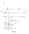
- Fig. 1 is a transmitting antenna system 1 with a transmission power of at least 2 kW and with a monitoring of an electrical conductivity property of the transmitting antenna system 1 refer.
- the transmitting antenna system 1 has a first transmitting antenna 3, which is supplied via a power transport path 2 with signals to be emitted via the first transmitting antenna 3.
- the supply of the first transmitting antenna 3 with the signals to be emitted takes place from a transmitter 8.
- the infrastructure of the first transmitting antenna 3 for monitoring a electrical line property of the transmitter a built-in part 4, which is arranged in the illustrated embodiment of the transmitting antenna system 1, for example in the casing of the power transport path 2.
- the resistance measuring device 5 has a DC voltage source 6 and a resistance measuring device 7. Starting from the transmitter 8, in addition to the wiring leading to the first transmission antenna 3, four further cables are shown, which extend to other antennas, which extend into Fig. 1 but not shown.
- Fig. 2 schematically is an embodiment of a built-in part 4 with at least one coupling of a resistance measuring device in a power transmission path of a transmitting antenna system with a transmission power of at least 2 kW to take.
- Fig. 2 is to take a housing 21 within which a Gleichstromeinspeiseglied (22) is arranged.
- the DC infeed member has a first contact element 12 for coupling to the transmitter, a second contact element 13 for coupling to the power transport path, and a third contact element 14.
- the third contact element 14 serves to connect a DC voltage source and / or a measuring device for determining the resistance.
- a device combination is connected, which has a DC voltage source and / or a measuring device for determining the resistance.
- a commercially available insulation measuring device is connected to the third contact element 14.
- a DC voltage for energizing the power transport path is fed to the power transport path via the DC feed member 22 located in the fixture 4.
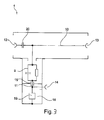
- Fig. 3 is an embodiment of a built-in part 4 with at least one coupling of a resistance measuring device 5 in a power transport path 2 of a transmitting antenna system with a transmission power of at least 2 kW.
- the mounting part 4 is designed as a compact part, which is arranged completely in a housing 21.
- the built-in part 4 comprises in the embodiment shown a direct current injection element whose design is shown in the circuit diagram shown within the housing 21.
- the DC feed member has a first contact element 12 and a second contact element 13.
- the first contact element 12 is provided for the connection of the built-in part 4 with a transmitting side, in the embodiment shown with a transmitting system, the transmitting antenna system.
- the transmitting side of the transmitting antenna system is connected to a power transport path 2 which is connected to the second contact element 13 with the built-in part.
- the power transport path 2 starting from the contact made, leads to at least one first transmitting antenna 3.
- the first connecting line 10 has an isolating capacitor 20, which capacitively couples the transmitting station and the power transport path. The capacitive coupling ensures that the first connection line is permeable to the alternating current, which is used for the transport of the transmission signal. In contrast to a transport of a direct current, the first connecting line via the isolating capacitor 20, however, is largely blocked, so that, for example, a feeding of interference signals in the power transport path is avoided.
- a second connecting line 11 is arranged on the side of the separating capacitor 20, which faces the second contact element 13, a second connecting line 11 is arranged.
- the second connection line 11 connects the power-transport-side section of the first connection line 10 and the infrastructure connected to the second contact element 13 to the third contact element 14.
- the third contact element 14 is provided for the intended coupling of the resistance measuring device in the power transport path.
- a coupling member 9 is arranged for coupling the resistance measuring device in the power transport path.
- the coupling member 9 is formed as a parallel arrangement of a capacitor and a coil. The connection of the coupling member 9 with the third contact element 14 via a transition capacitor 15.
- a surge arrester 19 is formed as part of the Gleichstromeinspeiseglieds parallel to the third contact element 14.
- the surge arrester is disposed within a RF-neutral space 16.
- the surge arrester is designed in the embodiment shown as a gas discharge surge arrester.
- the gas discharge surge arrester It is able to neutralize electromagnetic pulses of natural origin, such as direct or indirect lightning strikes, and thereby keep them away from the connected equipment.
- the neutralization of electromagnetic pulses from the connected devices is formed by the arrangement of the surge arrester 19 within the RF neutral space 16 and by the electrostatic separation of the remaining components of the Gleichstromeinspeiseglieds by means of a transition capacitor 15 in a particularly efficient manner.
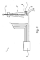
- Fig. 4 shows a further embodiment of a built-in part 4 with at least one coupling of a resistance measuring device 5 in a power transport path 2 of a transmitting antenna system.
- the transmitting antenna system has a transmission power of at least 2 kW.
- a fitting 4 modified to the effect that the connection of the second contact element 13 with the third contact element 14 via a coupling member 9, which in contrast to the embodiment of Fig. 4 is formed as a ⁇ / 4 stub.
- the ⁇ / 4 stub line is connected to the high-frequency resonance of the connected to the third contact element in the Fig. 4 Not shown first transmitting antenna 3 and adapted to this leading power transport path.
- the ⁇ / 4 stub is an empty line, by means of which the circuit targeted a reactance is provided.
- an insulation measuring device is connected to the third contact element 14, which provides for simultaneous application of the direct current voltage to the power transport path 2 and measurement of the ohmic resistance of the power transfer subjected to the DC voltage.
- a stationary insulation meter of the type ST 2383 Sourcetronic GmbH, Fahrenheltstrasse 1, D-28359 Bremen, with an adjustable measuring voltage between 10 V and 1000 V and an isomeas of 100 kOhm and 10 TOhm with an adjustable signal window can be used.
- An evaluation can be made via an acoustic signal with a binary output of a signal below a previously defined and set limit value.
- a triggering and / or an evaluation of the measured data can take place via an interface interface RS 232.
- the measuring cycle is adjustable.
- FIG. 5 Another embodiment of a built-in part 4 with coupling at least one resistance measuring device 5 is Fig. 5 refer to.
- the design of the Fig. 5 is in its basic arrangement of the formation of the Gleichstromeinspeiseglieds the embodiment of a component of the Fig. 3 comparable.
- Fig. 5 In addition to the positional orientation of the components to each other, there is a significant difference Fig. 5 to the embodiment of Fig. 3 in the embodiment of the first contact element 12 and the second contact element 13.
- the first contact element 12 and the second contact element 13 are in the Fig. 5 to be removed embodiment designed as sockets.
- the capacitor 10 is formed to improve the capacitive separation of the first contact element 12 and the second contact element 13 as a ceramic plate.
- the ceramic plate shown for example, has a capacity of at least 500 micro-rat.
- the in the Fig. 5 The embodiment shown corresponds in its design, for example, a stirrup connector, as used in many cases at a feed line beginning of a transmitting antenna system, in which the resistance measuring device is arranged integrated.
Landscapes
- Physics & Mathematics (AREA)
- Electromagnetism (AREA)
- Engineering & Computer Science (AREA)
- Computer Networks & Wireless Communication (AREA)
- Signal Processing (AREA)
- Measurement Of Resistance Or Impedance (AREA)
Applications Claiming Priority (1)
| Application Number | Priority Date | Filing Date | Title |
|---|---|---|---|
| DE102013014476.0A DE102013014476A1 (de) | 2013-09-02 | 2013-09-02 | Sendeantennenanlage mit einer Überwachung einer elektrischen Leitungseigenschaft und Einbauteil mit einer Einkopplung einer Widerstandsmesseinrichtung |
Publications (1)
| Publication Number | Publication Date |
|---|---|
| EP2848950A1 true EP2848950A1 (fr) | 2015-03-18 |
Family
ID=51535303
Family Applications (1)
| Application Number | Title | Priority Date | Filing Date |
|---|---|---|---|
| EP14003004.0A Withdrawn EP2848950A1 (fr) | 2013-09-02 | 2014-09-01 | Installation d'antenne radio avec la surveillance d'une propriété électrique d'un câble et une partie de montée à coupler une unité de mesure de résistance. |
Country Status (2)
| Country | Link |
|---|---|
| EP (1) | EP2848950A1 (fr) |
| DE (1) | DE102013014476A1 (fr) |
Families Citing this family (1)
| Publication number | Priority date | Publication date | Assignee | Title |
|---|---|---|---|---|
| EP3224902B1 (fr) * | 2014-11-25 | 2020-03-18 | Media Broadcast GmbH | Dispositif de surveillance pour une installation d'antennes d'émission et procédé de surveillance d'une installation d'antenne d'émission |
Citations (8)
| Publication number | Priority date | Publication date | Assignee | Title |
|---|---|---|---|---|
| US2637533A (en) * | 1949-09-24 | 1953-05-05 | Andrew Corp | Multi-v fm antenna |
| US4286238A (en) * | 1978-12-29 | 1981-08-25 | Thomson-Csf | Harmonic filtering device for radio transmitter |
| US20030223160A1 (en) * | 2002-05-31 | 2003-12-04 | Henry Pixley | Ground fault circuit interrupter for coaxial drop cable and method of operation |
| JP2004085355A (ja) * | 2002-08-27 | 2004-03-18 | Hitachi Cable Ltd | 温度測定装置および温度監視システム |
| GB2454236A (en) * | 2007-11-02 | 2009-05-06 | Stanelco Rf Technologies Ltd | Radio frequency cable monitor |
| JP2010010841A (ja) * | 2008-06-24 | 2010-01-14 | Toyota Motor Corp | 無線通信装置 |
| WO2010108330A1 (fr) * | 2009-03-27 | 2010-09-30 | Siemens Aktiengesellschaft | Système de radiocommunication et procédé de communication entre station de base et antenne |
| WO2012060414A1 (fr) * | 2010-11-02 | 2012-05-10 | 矢崎総業株式会社 | Dispositif de test à haute tension |
Family Cites Families (2)
| Publication number | Priority date | Publication date | Assignee | Title |
|---|---|---|---|---|
| DE3013755A1 (de) * | 1980-04-10 | 1981-10-15 | geb. Jacob Ursula 4330 Mülheim Nies | Verfahren und antennen-checker zur ueberpruefung von autoantennen |
| IT1275418B (it) * | 1995-06-02 | 1997-08-05 | Forem Spa | Polarizzatore dc per alte potenze rf e bassa intermodulazione |
-
2013
- 2013-09-02 DE DE102013014476.0A patent/DE102013014476A1/de not_active Withdrawn
-
2014
- 2014-09-01 EP EP14003004.0A patent/EP2848950A1/fr not_active Withdrawn
Patent Citations (9)
| Publication number | Priority date | Publication date | Assignee | Title |
|---|---|---|---|---|
| US2637533A (en) * | 1949-09-24 | 1953-05-05 | Andrew Corp | Multi-v fm antenna |
| US4286238A (en) * | 1978-12-29 | 1981-08-25 | Thomson-Csf | Harmonic filtering device for radio transmitter |
| US20030223160A1 (en) * | 2002-05-31 | 2003-12-04 | Henry Pixley | Ground fault circuit interrupter for coaxial drop cable and method of operation |
| JP2004085355A (ja) * | 2002-08-27 | 2004-03-18 | Hitachi Cable Ltd | 温度測定装置および温度監視システム |
| GB2454236A (en) * | 2007-11-02 | 2009-05-06 | Stanelco Rf Technologies Ltd | Radio frequency cable monitor |
| JP2010010841A (ja) * | 2008-06-24 | 2010-01-14 | Toyota Motor Corp | 無線通信装置 |
| WO2010108330A1 (fr) * | 2009-03-27 | 2010-09-30 | Siemens Aktiengesellschaft | Système de radiocommunication et procédé de communication entre station de base et antenne |
| WO2012060414A1 (fr) * | 2010-11-02 | 2012-05-10 | 矢崎総業株式会社 | Dispositif de test à haute tension |
| EP2642306A1 (fr) * | 2010-11-02 | 2013-09-25 | Yazaki Corporation | Dispositif de test à haute tension |
Also Published As
| Publication number | Publication date |
|---|---|
| DE102013014476A1 (de) | 2015-03-05 |
Similar Documents
| Publication | Publication Date | Title |
|---|---|---|
| DE69820101T2 (de) | Überspannungsunterdrückungsvorrichtung | |
| DE102011079935B4 (de) | Überwachungsvorrichtung für eine Kabelmuffe und Kabelmuffe mit Überwachungsvorrichtung | |
| EP3139188B1 (fr) | Procédé et dispositif de recherche d'erreur d'isolation comprenant une détermination adaptative de courant de test | |
| DE2413345A1 (de) | Isoliertes rohrleitungssystem, insbesondere ein unterirdisches rohrleitungssystem fuer fernheizung | |
| EP2427940A1 (fr) | Dispositif de surveillance | |
| EP1090303B1 (fr) | Procede et dispositif pour la surveillance d'une ligne d'electrode d'une installation bipolaire de transport de courant continu a haute tension (c.c.h.t) | |
| EP1708239B1 (fr) | Générateur de plasma sous vide | |
| DE102013107968A1 (de) | Online-Überwachungssystem für den Einsatz in elektrischen Anlagen und Verfahren zu dessen Betrieb | |
| EP2848950A1 (fr) | Installation d'antenne radio avec la surveillance d'une propriété électrique d'un câble et une partie de montée à coupler une unité de mesure de résistance. | |
| EP1850501B1 (fr) | Couplage adaptatif et capacitif et procédé de transmission d'informations par un câble d'alimentation blindé d'un réseau de distribution d'énergie électrique | |
| EP2375543A1 (fr) | Procédé de surveillance d'une ligne de transport d'énergie, suppression de bruit par transmission répété de données | |
| EP3269015B1 (fr) | Procédé de détermination d'état et de localisation de défauts sur des dérivations isolées installées dans un système de protection extérieure contre la foudre | |
| DE202014100207U1 (de) | Koppler für Mittelspannungs-Powerline-Communication | |
| DE102008062659A1 (de) | Vorrichtung zur Diebstahl-Überwachung des Solargenerators einer PV-Anlage | |
| EP4484967B1 (fr) | Dispositif de test de tension capacitif | |
| EP3224902B1 (fr) | Dispositif de surveillance pour une installation d'antennes d'émission et procédé de surveillance d'une installation d'antenne d'émission | |
| DE102007008263B4 (de) | Überwachungsvorrichtung für eine Zweidraht-Leitung, Gefahrenmeldesystem mit der Überwachungsvorrichtung | |
| AT522128B1 (de) | Überprüfen von Mantelspannungsbegrenzern | |
| EP0745862A2 (fr) | Procédé et appareil pour déterminer les propriétés d'isolation d'objets à examiner | |
| DE202014011102U1 (de) | Elektrische Schaltvorrichtung mit einem eingebauten Verbindungssystem zum Verbinden einer Messungseinrichtung und Einspeisen und Erfassen von niederfrequenten und hochfrequenten Signalen | |
| DE19515068A1 (de) | Anordnung zur TE-Detektion in Hochspannungskabeln und in deren Verbindungselementen | |
| DE102006045083A1 (de) | Schienenfahrzeug mit einer Branddetektionseinrichtung | |
| DE102018219959A1 (de) | Verfahren und Messanordnung zur Fehlererkennung auf elektrischen Leitungen | |
| AT516165B1 (de) | Detektieren des unbefugten Entfernens von Erdungsleitern | |
| DE102019133121A1 (de) | Feldgerät sowie Verfahren zum Betreiben eines Feldgerätes |
Legal Events
| Date | Code | Title | Description |
|---|---|---|---|
| PUAI | Public reference made under article 153(3) epc to a published international application that has entered the european phase |
Free format text: ORIGINAL CODE: 0009012 |
|
| 17P | Request for examination filed |
Effective date: 20140901 |
|
| AK | Designated contracting states |
Kind code of ref document: A1 Designated state(s): AL AT BE BG CH CY CZ DE DK EE ES FI FR GB GR HR HU IE IS IT LI LT LU LV MC MK MT NL NO PL PT RO RS SE SI SK SM TR |
|
| AX | Request for extension of the european patent |
Extension state: BA ME |
|
| STAA | Information on the status of an ep patent application or granted ep patent |
Free format text: STATUS: THE APPLICATION HAS BEEN WITHDRAWN |
|
| 18W | Application withdrawn |
Effective date: 20150923 |