EP3224902B1 - Dispositif de surveillance pour une installation d'antennes d'émission et procédé de surveillance d'une installation d'antenne d'émission - Google Patents
Dispositif de surveillance pour une installation d'antennes d'émission et procédé de surveillance d'une installation d'antenne d'émission Download PDFInfo
- Publication number
- EP3224902B1 EP3224902B1 EP15767114.0A EP15767114A EP3224902B1 EP 3224902 B1 EP3224902 B1 EP 3224902B1 EP 15767114 A EP15767114 A EP 15767114A EP 3224902 B1 EP3224902 B1 EP 3224902B1
- Authority
- EP
- European Patent Office
- Prior art keywords
- signal
- antenna system
- measuring
- transmitting antenna
- resistance
- Prior art date
- Legal status (The legal status is an assumption and is not a legal conclusion. Google has not performed a legal analysis and makes no representation as to the accuracy of the status listed.)
- Active
Links
Images


Classifications
-
- H—ELECTRICITY
- H01—ELECTRIC ELEMENTS
- H01Q—ANTENNAS, i.e. RADIO AERIALS
- H01Q1/00—Details of, or arrangements associated with, antennas
- H01Q1/50—Structural association of antennas with earthing switches, lead-in devices or lightning protectors
-
- H—ELECTRICITY
- H04—ELECTRIC COMMUNICATION TECHNIQUE
- H04B—TRANSMISSION
- H04B1/00—Details of transmission systems, not covered by a single one of groups H04B3/00 - H04B13/00; Details of transmission systems not characterised by the medium used for transmission
- H04B1/02—Transmitters
- H04B1/04—Circuits
- H04B1/0475—Circuits with means for limiting noise, interference or distortion
Definitions
- the present invention relates to a transmission antenna system monitoring device with an arcing sensor. Furthermore, a transmission antenna system monitoring device with several monitoring modules for the respective monitoring of different electrical parameters of the transmission antenna system is proposed.
- the invention also includes a method for monitoring a transmitting antenna system by means of at least one arc sensor.
- the detection device In the detection device according to the document DE-A-10 2015 001 493 there is no provision for evaluating the detection signal in a low-frequency range between 0 and 60 kHz. Also, the cited document does not provide for the detection signal to be coupled out by direct, galvanic connection to the inner conductor.
- WO-A-2014/032 650 describes a device and a method for arc detection in photovoltaic systems.
- Transmitting antenna systems of the type concerned here are VHF / DAB and DVBT transmitting antenna systems. These are used to send information to areas far away. This means that high-frequency electrical power must be used in order to be able to send these signals via a transmitting antenna, which is not comparable with those in smaller transmitting systems. This requires transmission power in the kW range.
- the generic transmission antenna systems are often arranged on steel lattice masts or on closed telecommunication towers in exposed positions. Due to the very long operating time of these systems, these are subject to various influences. Operating times of 30 years and longer are not uncommon, so that effects such as corrosion, material fatigue, condensation water storage or other changes can occur which affect and possibly endanger the operational safety of the transmitter antenna systems.
- the object of the present invention is therefore to permanently monitor the operational safety of such large transmitting antenna systems in order to identify possible emergency situations at an early stage.
- the solution to the problem is a monitoring device for a transmitting antenna system, which has a coaxial power transport path, which has an inner conductor and an outer conductor, with a measurement signal tapping line for electrical connection to the inner conductor and an evaluation and control unit with an input connected to the measurement signal tapping line and with one Output, and an interruption switch for interrupting the transmission signal supply to the transmission antenna system, the interruption switch being able to be switched on and off by means of an output signal from the evaluation and control unit, and the evaluation unit having a predetermined low-frequency range between 0 Hz and 60 kHz, in particular in an audible range Frequency range between 0 Hz and 20 kHz, 0 Hz and 19 kHz, 0 Hz and 15 kHz, 0 Hz and 5 kHz or 0 Hz and 4 kHz with compares a threshold value and, if the measured value in the said frequency range is greater than the threshold value, outputs a switch-off signal at its output for at least temporarily switching off the interruption switch.
- the evaluation and control unit has an arc or arcing detector.
- This detector evaluates the measurement signal in a predeterminable, preferred frequency range. It is advantageous to limit the evaluation to the frequency ranges mentioned, since the arcing signal can be detected particularly well in these frequency ranges.
- the frequency ranges mentioned are sufficiently far from the frequency range in which the useful signal is transmitted. This ensures that there is no significant overlay of useful and interference signals. As a result, the interference signal to be detected can be detected particularly well since it is separated from the useful signal.
- the direct, galvanic tapping of the signal on the inner conductor enables a low-resistance tapping of the signal.
- the evaluation and control unit can be supplied with a significantly stronger signal than would be the case if the tap were made inductively.
- the measured value compared with the threshold value represents an intensity value of the measurement signal.
- an intensity value that is measured at a single frequency can be compared with the predefinable threshold value. This intensity value can be measured, for example, at 60 kHz, at 20 kHz or at 19 kHz.
- the measured value is determined from a measurement in a predetermined frequency range. It is possible, for example, to add the arithmetic mean of the measurement signal in a frequency range from 0 Hz to 60 kHz or from 0 Hz to 20 kHz (or one of the previously mentioned frequency ranges) use that is compared to a threshold value. It is also possible to use the arithmetic mean of the amount of the measurement signal in one of the previously mentioned frequency ranges as the measurement value. Furthermore, the variance or the standard deviation of the measurement signal in a predeterminable frequency range can also be used as the measurement value.
- the evaluation and control unit automatically outputs a switch-on signal for the interruption switch after a switch-off signal and checks whether the measured value in the said frequency range is greater than the threshold value, whereupon if this is the case , the evaluation and control unit again outputs a switch-off signal for switching off the interruption switch.
- the interruption switch By repeatedly switching the interruption switch on and off, it can be checked whether the detected fault is a short-term fault or whether this fault is permanent. A malfunction often disappears after the transmitter antenna system has been switched off and on again. In this case, the fault can usually be ignored. However, if the fault is longer and cannot be remedied by simply switching it off and on, the transmitter antenna system can then be switched off permanently until the problem has been rectified by a service technician, for example.
- the evaluation and control unit alternately sends switch-on and switch-off signals for the interruption switch until the measured value in the said frequency range is greater than the threshold value, after a predetermined number of repetitions of the alternate output of switch-on and switch-off signals the circuit breaker remains switched off.
- the transmitting antenna system can be checked whether the fault can be remedied by switching the transmitting antenna system off and on several times. It can be specified how often the transmitting antenna system should be switched off and on before the transmitting antenna system is to be finally switched off. For example, it can be specified here that the transmitting antenna system is switched off and on a total of three times until it is finally switched off if the interference signal is still present.
- the measurement signal tapping line is a ⁇ / 4 line, where ⁇ is the wavelength of the carrier frequency of the transmission signal of the transmission antenna system.
- the evaluation and control unit impresses a measuring current into the inner conductor via the measuring signal tapping line and measures the resistance between the outer conductor and the inner conductor of the power path and, if the measured resistance is less is a predefinable minimum resistance, outputs a switch-off signal for the interruption switch at its output and / or outputs a display signal at its output for the optical display of the measured resistance or a value characterizing it.
- This measurement is an insulation resistance measurement.
- a malfunction or a deficiency in the antenna system can be detected early by measuring the insulation resistance. If the measured resistance falls below a predefinable threshold value, the transmitting antenna system is switched off and / or a warning is issued.
- the insulation resistance can decrease, for example, by the fact that moisture or wetness penetrates into the antenna system and this causes an increase in the conductivity of insulation components that are required for the design. As a result, there is a risk of a short circuit and damage or even destruction of the antenna system.
- the warning in the event of a detected malfunction can be given by an optical signal.
- LEDs can be arranged side by side in a chain, the lighting up of each individual LED being able to indicate the resistance range in which the measured resistance value is located.
- the evaluation and control unit carries out a measurement of the resistance of the electrical circuit comprising the inner conductor, outer conductor and antenna via the measurement signal tapping line, and if the measured resistance is greater as a predeterminable permissible maximum resistance, outputs a switch-off signal for the interruption switch at its output, and / or outputs a display signal for the optical display of the measured resistance or a value characterizing it.
- the resistance described which is also referred to as a loop resistance, is typically only a few 10 m ⁇ to a few 100 m ⁇ . If a greater resistance is measured, for example a resistance that is greater than or equal to 1 ⁇ , it can be assumed that at least one component of the antenna system is defective. This deficiency can arise in particular from signs of aging such as corrosion of individual antenna components.
- the antenna system to be monitored is permanently or even temporarily exposed to a DC voltage (i.e. permanent or even only a small amount of DC current always flows in the same electrical direction), ion migration can occur, resulting in material being shipped.
- the DC voltage fed in for measurement purposes must be re-keyed with a (albeit) very low frequency.
- the measurement signal tapping line can be connected galvanically to the inner conductor of a bridge connector of the transmitting antenna system.
- a method for monitoring a transmitting antenna system which has a power transport path with an inner conductor and an outer conductor, is proposed to achieve the aforementioned object, wherein in the method a measuring signal is tapped from the inner conductor via a measuring signal tapping line that is electrically connected to the latter, and a measured value of the measurement signal in a predeterminable frequency range between 0 and 60 kHz, in particular between 0 and 20 kHz, is compared with a threshold value and, if the measurement value in the said frequency range is greater than the threshold value, the supply of a transmission signal to the transmission antenna system is at least temporarily interrupted .
- a ⁇ / 4 line is used as the measurement signal tapping line, where ⁇ is the wavelength of the carrier frequency of the transmission signal of the transmission antenna system.
- a measurement current is impressed into the inner conductor via the measurement signal tapping line and the resistance between the outer conductor and the inner conductor of the power path is measured and if the measured resistance is less than a predeterminable minimum resistance, the supply of the transmission signal to the transmission antenna system is interrupted at least temporarily and / or a display signal for the optical display of the measured resistance or a value characterizing it is output.
- the measurement signal tapping line carries out a measurement of the resistance of the electrical circuit comprising the inner conductor, outer conductor and antenna and, if the measured resistance is greater than a predeterminable permissible maximum resistance, a switch-off signal for the interruption switch is output at its output and / or a display signal for visual display of the measured resistance or a value characterizing this.
- the measurement signal tapping line is electrically connected to the inner conductor of a bridge connector of the transmitting antenna system.
- a transmission antenna system with a power transport path with an inner conductor and an outer conductor and with a monitoring device with the aforementioned features and / or a method with the aforementioned features is proposed to achieve the above-mentioned object.
- a transmission antenna system monitoring device with an arcing sensor that monitors a noise component of a frequency range has an interrupter which interrupts a carrier loop of the transmitting antenna system.
- this interrupter is also referred to as an interruption switch.
- a controller is provided which is connected to the interrupter and triggers the interrupter as a function of a recorded smoke signal, the controller selecting between at least a brief interruption and a permanent interruption of the carrier loop as a function of the noise signal.
- the arcing fault sensor, the interrupter and also the controller are preferably arranged together on a carrier board. This allows, for example, the arcing sensor to be used as a single component, for example can be connected to the transmitter antenna system in its own housing.
- an arc detection board is accommodated in an attachment housing.
- This is connected directly to a jumper plug, for example.
- a jumper plug goes out of the DE 10 2013 014 476 , to which reference is made in full in the context of the disclosure.
- Such a bridge connector has, for example, a ⁇ / 4 stub line, via which the arcing sensor receives information regarding a noise spectrum.
- the sensor preferably has ideal low-resistance access to the inner conductor of the entire antenna system. This allows an arc to be detected that can occur anywhere in the antenna system.
- a power path between the transmission system, filter chain, mask filter and the RF switching field can preferably also be detected on an arc.
- the arrangement of the stirrup connector in front of the RF control panel means that the entire power path from the RF control panel can be checked.
- a further development provides that the check by means of the arc sensor is carried out permanently. This has the advantage that even briefly occurring noise can be detected directly and can be examined in the context of a control, possibly regulation, to determine whether it is an indication of an arc that has arisen or whether it is noise, for example due to atmospheric Disturbances in the power path has been generated. As a result, the arc sensor is able to detect even the smallest spark formation, which could be caused by contact or insulation problems.
- the arc sensor preferably monitors a predetermined frequency range. It is particularly preferred if this predeterminable frequency range can also be changed. According to a further embodiment, it is provided, for example, that different frequency ranges are monitored. This can, for example by a large number of arcing sensors assigned to a frequency range. Another embodiment in turn provides that a plurality of frequency ranges are assigned to an arcing fault sensor. By jumping between these different frequency ranges and scanning them in each case, a noise state can also be detected, which enables an indication of an error.
- the arcing fault sensor continuously detects the RF transport path for noise components in a range around 450 kHz. If the arc sensor now detects an abnormal noise component in the 450 kHz window, it is provided, for example, that this noise bell is monitored for its duration for a short period of time. If this noise bell lasts longer, for example 3 or more seconds, it can be provided that the interrupter interrupts the associated carrier loop. As a result, the transmission power of all transmitters on this antenna is briefly interrupted. Afterwards, however, the interruption is immediately canceled and the carrier loop is closed. If, after the transmitter or the transmitter has been briefly switched off, the noise components have disappeared, it can be provided, for example, that logging is carried out for this purpose, which is then used as part of regular maintenance of the transmitter antenna system, for example.
- the carrier loop is then permanently interrupted.
- One embodiment provides, for example, that multiple tests are carried out to determine whether the noise bell is produced again immediately after the carrier loop is opened and closed. For example, a repeated interruption and closing of the carrier loop can be provided, whereby after reaching an adjustable number of interruptions and closings, the carrier loop is no longer briefly interrupted but permanently.
- this is repeated three times in succession before the carrier loop remains permanently open. It is preferred that the permanent interruption of the carrier loop cannot be canceled again by the arc sensor or the associated control itself. Rather, it is preferably provided that another actuation is required to cancel the interruption. In particular, it is provided that this can only be done by manual resetting on site.
- restart can also be carried out using other activation options. For example, provision can be made that manual activation is necessary before the restart can be triggered, for example, by a remote control room.
- provision can be made that manual activation is necessary before the restart can be triggered, for example, by a remote control room.
- Detection can take place, for example, using different measuring devices at different locations on the carrier loop.
- a transmission antenna system monitoring device with a plurality of monitoring modules for the respective monitoring of different electrical parameters of the transmission antenna system.
- This transmission antenna system monitoring device is preferably provided with a first module with an insulation resistance measurement for monitoring a galvanically open antenna construction via a DC feeder switch of the transmission antenna system, with a second module with a low-resistance loop measurement of a resistance of an inner conductor in a power transport path, and with a third module , which has an arcing sensor, preferably an arcing sensor, as described above.
- the first module preferably has a high-resistance insulation measurement, such as that already mentioned above DE 10 2013 014 476 the applicant emerges.
- a high-resistance insulation measurement such as that already mentioned above DE 10 2013 014 476 the applicant emerges.
- the insulation resistance measurement is preferably carried out permanently, the insulation resistance of galvanically open antenna constructions being monitored via a direct current feed switch.
- This DC feed-in switch emerges from the above-mentioned document.
- the resistance is determined by a simultaneous current and voltage measurement.
- a current-correct measuring circuit is used for this.
- the measurement results are processed in an electronic module, decoded in a display module and displayed using an LED chain.
- An external constant current source supplies this measuring device with an operating voltage.
- the display can also take place in another way, the LED chain making it possible to clearly display a wide variety of resistance values.
- These resistance values have a size of 10 k ⁇ , 100 k ⁇ , 1 M ⁇ , 10 M ⁇ and 100 M ⁇ , for example.
- this high-resistance measurement showed that measured values of 10 k ⁇ and less should serve as an alarm threshold for transmit antenna systems of the type mentioned. Therefore, for example, according to one embodiment, it is provided that when a resistance value of 10 k ⁇ or less is reached, this is used to provide a potential-free contact. An alarm can then also be triggered when the measured value of 10 k ⁇ and less is reached.
- the measured values of 100 k ⁇ to 100 M ⁇ are more of an informative character, but can provide information as part of longer-term maintenance monitoring. If, for example, a measured value of 10 k ⁇ or less is determined as part of the LED display, a red LED lights up. If, on the other hand, a measured value of 100 k ⁇ and more is achieved, a green LED will light up.
- the resistance values and the limit value are only given as examples. Other values can also be used. Instead of discrete value displays, concrete value displays of the measured resistances can be determined or displayed and, if necessary. to be processed further.
- the second module preferably has a low-resistance measurement. This is intended for transmit antenna systems that are galvanically closed. Like the first module, the second module is preferably able to access the electrical antenna structure via the bridge connector. Using a low-impedance loop measurement, the resistance of the inner conductor of the power transmission path of the transmission antenna system between the bow connector over the entire RF piping of the feed line and all the plug-in connections up to the distributors is preferably permanently monitored. As in the first module, the resistance is preferably determined by a simultaneous current and voltage measurement, in this way a voltage-correct physical measurement is carried out.
- the voltage source used for the resistance measurement reverses the polarity of the applied voltage at predetermined time intervals makes. This can prevent a unipolar voltage from causing ion migration over a longer period of measurement, ie over several days, months or years, which would consequently lead to material loading.
- the measure of the alternating voltage is particularly advantageous in the monitoring device according to the invention, since a permanent and permanent measurement of the transmitting antenna system is desired here.
- the DC voltage is represented by a square-wave signal, which changes between a positive and a negative value. This change can take place at a low frequency, for example at a few Hz or in the mHz range. It can also be provided that the polarity reversal of the voltage takes place after a few minutes or hours. Furthermore, it can be provided that instead of a DC voltage, an AC voltage is used to measure the insulation resistance or the loop resistance.
- the measurement results obtained in this way are in turn processed in an electronic module, decoded in a display module and brought to the attention by means of a display.
- An LED chain can also be used here. It is preferred, for example, that an external constant current source is used to provide the measuring device of the second module with an operating voltage.
- This low-resistance measurement allows, for example, a display to be divided into the following or similar steps: 50 m ⁇ , 100 m ⁇ , 250 m ⁇ , 500 mQ and 1 ⁇ . While the measured values from 50 mQ to 250 mQ are displayed using a green LED, for example, a red LED is triggered when 500 mQ or 1 ⁇ is reached. If a resistance value of 500 mQ and more is reached, an alarm message is preferably also carried out.
- a further embodiment provides that the first, the second and the third module are arranged together in one housing.
- This housing is preferably in turn arranged in a bow connector, as described above.
- first, the second and the third module are accommodated in a common housing which is arranged on a bridge connector.
- this enables the first, the second and / or the third module to use the components contained in the bridge connector, such as a ⁇ / 4 stub.
- a constant current source can also be provided in the bridge connector, for example, which is capable of supplying at least the first and the second module with a sufficient operating voltage.
- the first and the second module are each connected to a display, the display being supplied with a signal which characterizes a measured resistance value.
- the use of separate displays, which are preferably arranged on the housing and in which the first and the second module are located, allows the transmitting antenna system monitoring device to be transportable, in particular. This can be done for example by arrangement on the bridge connector. However, it can also be arranged at a different location of the transmitting antenna system, depending on where an interface is provided or can be set up, which enables the different modules to perform their respective monitoring tasks.
- the first and the second module each have a separate threshold value with regard to a recorded measured value, an alarm function being connected to the respective threshold value.
- the threshold value is preferably set depending on the transmission antenna system that is to be monitored. This threshold value can also be set, for example, depending on the antenna that is to be checked. This allows, for example, identical or similar transmitter antenna system monitoring devices to be manufactured in a basic configuration and then adapted to the respective transmitter antenna system, compared with corresponding parameters available there and adjusted. This way, several transmitting antenna system monitoring devices can also be used can be used in a radio mast or transmission tower, each of which can monitor different power paths or sections thereof, overlapping but also separately from one another.
- the first and the second module have a common switch, by means of which it is possible to switch between the first and the second module.
- the switch is connected to the display panel, the LED chain or another display, for example. This enables a user to display different modules.
- the switch can be operated manually. But there is also the possibility that a changeover switch can be triggered by other modes of operation. It is preferred here that the display is housed together with the modules in or on a housing. Furthermore, a changeover switch can be provided if it is to be switched between different modules or measurements.
- the arcing fault sensor has an IP interface for communication and preferably also a potential-free contact, via which the hot carrier loop of the connected transmitter or transmitters can be opened.
- one or more of the modules can each have at least one IP address, an IP interface being provided on the housing. The respective modules can then be connected to this IP interface.
- Another embodiment provides that administrator rights can be assigned to the circuit board on which the arc sensor is arranged. Via access via a fixed IP address, an administrator can then, for example, access the arcing fault sensor or the local time switch of the control in order to make changes. This can, for example Changes regarding the duration, the short-term interruption, the repetition of this short-term interruption as well as, for example, the frequency band to be monitored.
- a further use of the proposed transmission antenna system monitoring device is to be able to carry out a quality assessment of the transmission antenna system. If, for example, an initial measurement is carried out when the transmitting antenna system is started up, such parameters as DAB, VHF or DVBT transmitting antenna systems can be recorded at the beginning. If changes then occur in the operation of the respective transmitting antenna, in particular creeping damage, this can be detected via the various modules. In particular, a slowly advancing change in resistance, recorded by the first or second module, can provide information as to where appropriate, in particular also where revisions to the transmission antenna system might be due in the future. This allows, for example, better planning of revision periods in order to prevent damage that occurs during a previous, i.e. previous revision, could have been avoided.
- the proposed transmission antenna system monitoring device is arranged portably, but permanently on the transmission antenna system. This allows constant monitoring of the various electrical parameters.
- a method for monitoring a transmitting antenna system by means of at least one arc sensor is proposed.
- a transmission antenna system monitoring device can be used here, as has already been described above.
- the arcing fault sensor monitors a carrier loop of the transmitting antenna system, the carrier loop being interrupted at least once briefly when a noise component is detected, then the carrier loop being closed again, provided that the noise signal is still detected after the carrier loop has been opened and closed at least once, the carrier loop is finally interrupted permanently.
- a further development of the method provides that, in the event of a permanent interruption of the carrier loop by the arcing sensor, an interfering signal is triggered which is forwarded to a remote control room remote from the transmitting antenna system.
- the IP interface presented above can be used for this purpose, for example. This allows a large number of transmitting antenna systems distributed over a very large area to be monitored simultaneously at a single remote control room. In particular, this also enables automated monitoring, in which an actual damage incident or a threshold value is only triggered to the operating team before the start of a damage incident, if this has been determined and forwarded by one of the modules or by the arc sensor.
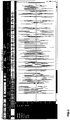
- Fig. 1 shows in an exemplary embodiment a so-called "sturgeon mist" as it arises when an arc is generated.
- An arc spectrum is shown, which was recorded with an arc demonstrator, applied to a VHF test case with 100 MHz and 600 W.
- the interference fog resulted with a measuring device Rohde & Schwarz FSH 3, which was between 10 and 20 mV with an attenuation of 10 dB had in the entrance.
- the arc creates an interference mist that extends from the LF range to approximately 1.5 GHz. If such a nebula is detected, the arcing sensor is able to interpret this determined noise component in such a way that the interrupter interrupts the performance in the carrier loop.
- Fig. 2 shows an exemplary view of an evaporation process in the low-frequency frequency range audible to the human ear
- this recording shows a real decomposition process of approx. 2cl water in the wiring of a transmitting antenna system operated with a radio frequency power of approx. 500 W at an operating frequency of 100MHz.
- the spectrum recorded shows the characteristics of an arcing fault caused by the penetration of moisture.
- the arcing fault signal can be clearly recognized in the low-frequency, audible range.
- the interference signal can be detected particularly well in the frequency range from 0 Hz to 15 kHz.
- the chaotic interference signal can be evaluated as described above.
- an intensity value of the measurement signal, which was recorded at a specific frequency can be compared as a measured value with a threshold value.
- the measured value, which was recorded at a frequency of 19 kHz can be compared with a threshold value. If this measured value is above the threshold value, an interference signal is accepted.
- a frequency range such as the range between 0 kHz and 5 kHz or between 0 kHz and 4 kHz can also be evaluated, for example. For example, an average value of the measurement signal within this frequency range can be compared with a predefined threshold value.
- the detection of arcing faults using the described method also takes place in the early stages of damage, so that it is still possible to repair the transmitting antenna system before irreparable damage has occurred. Even slight rollovers can be detected with the monitoring device according to the invention.
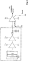
- Fig. 3 shows a schematic view of a block diagram of a possible arc detection, as is explained in more detail in the following publication.
- Arc sensors are known in the prior art. For example, go out of the WO 2014/032650 A1 a method and an apparatus for arc detection. This as well as the resulting block diagram can be used to provide an arc sensor accordingly. On the relevant content of this publication is in Scope of disclosure referred to.
- other arc sensors can also be used.
- arc detections that are arranged in the inverter. These are housed on a circuit board and allow the monitoring of solar cells there.
- Such boards can also be used for transmitting antenna systems in order to detect arcing faults, such as can occur, for example, in the case of damaged connecting terminals, corroded cables, worn insulation or other damage events in the area of the transmitting antenna system.
- arcing faults such as can occur, for example, in the case of damaged connecting terminals, corroded cables, worn insulation or other damage events in the area of the transmitting antenna system.
- noise by an arc generated there is the possibility that an arc is also detected in a different way.
- the monitoring has proven to be particularly advantageous in that the arc can be inferred on the basis of noise and thus the entire power path can also be monitored.
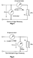
- Fig. 4 again shows a current-correct measurement in an exemplary circuit diagram
- Fig. 5 shows a voltage-correct measurement of the resistance. Both options are used in the first and in the second module, whereby from Fig. 6 an exemplary embodiment of the resistance measuring circuit for the first module emerges.
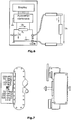
- Fig. 7 shows a schematic view of a stirrup connector, as has been discussed in more detail above, based on the patent application filed by the applicant.
- a housing for accommodating the resistance measuring device, the display electronics and also the internal arc sensor can be provided on this stirrup plug and on the devices there.
- a first LED chain can be provided, for example, which displays high-resistance measurement values, while a second LED chain displays low-resistance measurement values.
- the switch shown there it is possible to switch between a low-resistance and a high-resistance measurement.
- the transmitting antenna system to be monitored has at least one power transport path for supplying power to at least one first transmitting antenna and at least one resistance measuring device for determining an ohmic resistance for monitoring the transmitting antenna system.
- the resistance measuring device comprises at least one DC voltage source for applying a measurement DC voltage to at least the section of the power transport path. Furthermore, the resistance measuring device has at least one measuring device for determining the resistance of the section to which the DC measurement voltage is applied.
- the proposed monitoring can be used in a functional manner for transmission powers of up to 50 kW, preferably of preferably 2 kW to 50 kW.
- a measuring device for determining the resistance can be an ohmmeter, but it can also be additionally or alternatively provided, for example, that a measuring device is provided which provides for an indirect determination of a resistance.
- a redundancy measurement can be provided, for example for comparison and / or for cross-checking.
- an indirect determination can be provided by determining an electrical current and / or an electrical voltage.
- the resistance measuring device is arranged in an electrical feed line area of the power transport path.
- the feed line area of the power transport path denotes an area of the transmission antenna system, which is preferably designed as an RF cable or as an RF cable bundle, which leads to the first transmission antenna.
- the resistance measuring device is arranged on or in an HF cable or on or in a piping section of the power transport path.
- An advantage of arranging the resistance measuring device on or in an HF cable or on or in a piping section of the power transmission path is, for example, that the direct arrangement on the already existing infrastructure of the transmitting antenna system enables the resistance measuring device to be attached inexpensively while at the same time being efficient works and can be positioned flexibly.
- a resistance measuring device can be arranged such that it can be moved.
- Another embodiment provides, for example, that the resistance measuring device is not permanently installed. Rather, according to one embodiment, it can be arranged completely or at least partly only temporarily or arranged in the power transport path.
- a transportable checking device can be used to check the power transport path or to check the permanently installed monitoring of the power transport path in accordance with the system described here.
- the resistance measuring device is arranged at the start of a feed line.
- Arranging the resistance measuring device at the start of a feed line has the particular advantage of being able to enable complete monitoring of the infrastructure located beyond the start of the feed line against changes in resistance. In particular, this enables complete monitoring of the power transport path and the transmitting antenna against changes in resistance.
- the resistance measuring device is arranged in a switchgear panel that can be fitted at the start of the feed line.
- installing the resistance measuring device in a switchgear panel at the start of the feed line has the advantage that components that are already available and are intended to be inserted into the switch panel can be modified and used with the integrated resistance measuring device to such an extent that the existing infrastructure can otherwise be used largely unchanged .
- stirrup plug it can also be provided here, for example, that more than one stirrup plug are used in a parallel arrangement.
- the resistance measuring device is completely or partially installed in a stirrup plug which has at least one direct current feed element.
- the resistance measuring device has a direct current feed element.
- the power transport path of the transmitting antenna system which is provided for the transport of high-frequency power during operation, can be supplied with a direct current.
- the direct current feed element has a first contact element and a second contact element. It can further be provided that the first contact element and the second contact element are capacitively coupled, for example by means of at least one capacitor.
- the capacitive coupling means that the RF power to be transported can continue to pass between the transmitter and the power transport path, but the path for a direct current is blocked due to the capacitive coupling.
- a second connecting line leading to a third contact element is arranged starting from a first connecting line between the first contact element and the second contact element.
- the second connection line is starting from a side of the first connection line which faces the power transport path side of the capacitor. This creates a possibility of connecting the power transport path to one end of the second connecting line, whereas connecting one end of the second connecting line to the transmitter system via a direct current is prevented by the capacitive coupling of the first contact element.
- the second connecting line has at least one coupling element of the direct current feed element for connecting the second contact element to the third contact element.
- the coupling element is designed as a ⁇ / 4 stub line adaptation to the transmission antenna or as an L-C parallel resonant circuit.
- the coupling member is designed as a throttle.
- the advantage of introducing a coupling element which is designed as a ⁇ / 4 stub line adaptation, as an LC parallel resonant circuit or as a choke, is, among other things, a damping in the direction of the measuring device and / or the DC voltage source that occurs by means of destructive interference of the AC voltage leading to the power transport path so that they are separated from the AC components of the transmitter antenna system.
- the design of the coupling element with a bandwidth of a frequency range emitted by the transmitting antenna is carried out, for example, in such a way that that the coupling element filters a frequency approximately in the middle of the frequency range.
- a coupling element as a ⁇ / 4 stub line adaptation
- the second connecting line has a transition capacitor of the direct current feed element arranged between the coupling element and the third contact element.
- an RF-neutral space of the direct current feed element is arranged between the coupling element and the third contact element, which preferably has a gas discharge surge arrester.
- the resistance measuring device is connected to the system preferably has an interchangeable and / or pluggable built-in part which contains at least the direct current feed element.
- Embodiments are also possible in which the direct current feed element, the direct current source and / or the measuring device are arranged in a compact component.
- a connection to the first socket, the second socket and / or the third socket can be resolvable, which has the particular advantage that the resistance measuring device or components of the resistance measuring device are interchangeable.
- the direct current feed element is provided as a compact component and that the direct current feed element is present as an exchangeable built-in part.
- a connection of the third socket to the direct current source and / or the measuring device, or a connection of the third socket to the insulation measuring device is designed to be non-destructive, for example as a welded connection.
- a DC measurement voltage with a value between 48V and 500V can be provided.
- a DC measurement voltage with a value of 48V can preferably be provided. Different DC measuring voltages can also be used, which are preferably within the specified range.
- the transmitting antenna system is a radio antenna system.
- Another idea of the invention which can be used as a function of and independently of the transmission antenna system described above, relates to an installation part.
- an installation part can be provided, for example, whose first contact element and second contact element are capacitively coupled by means of at least one capacitor of the direct current feed element.
- it can be provided, for example, that starting from a first connecting line of the direct current supply element between the first contact element and the second contact element, preferably oriented on the power transport side of the capacitor, a second connecting line of the direct current supply element leading to the third contact element is arranged.
- a coupling member can be provided that is provided as part of the second connecting line.
- the coupling element is preferably designed as a ⁇ / 4 stub line adaptation to the transmission antenna and / or as an L-C parallel resonant circuit.
- the second connecting line has a transition capacitor arranged between the coupling element and the third contact element and that an HF-neutral one is provided between the transition capacitor and the third contact element Space of the DC supply element is arranged, which preferably has a surge arrester.
- the third contact element is a two-pole socket with a first pole and a second pole, one of the two poles being an earth pole.
- a resistance measuring device is arranged so that it can be replaced on the built-in part.
- Another idea of the invention which can be used depending on how independently of the transmission antenna system described above, relates to a method for monitoring an electrical line property of a transmission antenna system with a transmission power of at least 2 kW.
- the transmitting antenna system has at least one power transport path and at least one first transmitting antenna.
- At least a section of the power transport path is subjected to a DC measurement voltage and an ohmic resistance determination is carried out at least of the section of the power transport path.
- the ohmic resistance is determined as a function of time.
- an alarm signal is output when the resistance falls below a predetermined threshold, preferably when the resistance falls below between 100 kOhm and 500 kOhm, particularly preferably when the resistance falls below between 150 kOhm and 250 kOhm.
- the values mentioned here are low enough to avoid any false alarms due to a weather-related lowering of the resistance values, for example due to high air humidity and / or salty air.
- the ohmic resistance determination is preferably carried out with a controlled resistance determination in a continuous manner or at predetermined times.
- a transmission antenna system for the monitored operation of a telecommunications system with continuous or regularly recurring insulation measurement by providing at least a section of the power transmission path of the transmission antenna system with a DC measurement voltage and ohmic resistance determination of the section of the power transport path can be provided.
- provision can be made for measurements to be carried out at equidistant intervals. This does not necessarily require active regulation, but can be controlled according to a previously defined schedule.
- measurements take place at an interval of N hours between an i-th measurement and an (i + 1) -th measurement, where i is a positive natural number that is used as a running index.
- the number N can be a positive decimal number between 2 and 10, preferably between 4 and 8, particularly preferably between 5 and 7.
- the measurement result can be displayed directly on site.
- the measurement result is transmitted, for example via a bus system.
- a remote transmission can be provided, which enables monitoring far from the transmitter system.
- This can be a central monitoring center, for example, which is able to monitor a plurality of transmitter systems, transmitter masts and radio towers at different locations.
- Monitoring is preferably computer-controlled.
- a measurement can not only be monitored, but also triggered by a computer.
- the measurement results are preferably stored and can be evaluated automatically, for example statistically. For example, a repair can be triggered, especially a predictive check, before major damage can occur.
- a radio tower can have a plurality of such monitors distributed along the power transport path, preferably one behind the other at greater distances along the path. This not only enables the entire measurement of the power transport path, for example. Rather, it is possible to better locate one or more fault locations along the power transport path by means of the respective measurement. For example, a deviation can be detected by a comparison with a reference measurement. If the measurement begins with a monitoring device that is located closest to the transmitting antenna, but there are no or only slight deviations from the reference measurement, the measurement at the next monitoring device located further away from the transmitting antenna can then be used to determine whether has set a deviation outside of a tolerance. In this way, the test can continue to be carried out until a deviation is finally found outside of it Tolerance lies. This allows the location of the fault to be narrowed down, which makes work in a radio tower easier, for example.
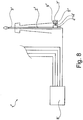
- a transmission antenna system 1 'with a transmission power of at least 2 kW and with monitoring of an electrical line characteristic of the transmission antenna system 1' can be seen.
- the transmitting antenna system 1 ' has a first transmitting antenna 3', which runs over a power transport path 2 'is supplied with signals to be emitted via the first transmitting antenna 3'.
- the supply of the first transmitter antenna 3 'with the signals to be emitted takes place from a transmitter system 8'.
- the infrastructure of the first transmitter antenna 3' has a built-in part 4 'for monitoring an electrical line property of the transmitter system, which in the embodiment shown shows the Transmitting antenna system 1 'is arranged, for example, in the piping of the power transport path 2'.
- a resistance measuring device 5 'designed as an insulation measuring device is arranged on a third contact element 14' of the built-in part 4 '.
- the resistance measuring device 5 ' has a DC voltage source 6' and a resistance measuring device 7 '.
- four further cables can be seen, which run to further antennas, which in FIG Fig. 8 but are not shown.
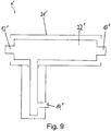
- FIG. 9 A configuration of an installation part 4 ′ with at least one coupling of a resistance measuring device into a power transport path of a transmitting antenna system with a transmitting power of at least 2 kW can be seen schematically.
- Fig. 9 a housing 21 'can be seen within which a direct current feed element (22') is arranged.
- the direct current feed element has a first contact element 12 'for coupling to the transmitter system, a second contact element 13' for coupling to the power transport path and a third contact element 14 '.
- the third contact element 14 ' is used to connect a DC voltage source and / or a measuring device for determining the resistance.
- a device combination is connected, which has a DC voltage source and / or a measuring device for determining the resistance.
- a commercially available insulation measuring device is connected to the third contact element 14 '.
- a DC voltage to act on the power transport path is fed into the power transport path via the direct current feed element 22 ′, which is located in the installation part 4 ′.
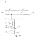
- FIG. 10 An embodiment of an installation part 4 'with at least one coupling of a resistance measuring device 5' into a power transport path 2 'can be found in a transmitting antenna system with a transmitting power of at least 2 kW.
- the built-in part 4 ' is designed as a compact part which is arranged entirely in a housing 21'.
- the installation part 4 ' comprises a direct current feed element, the design of which is shown in the circuit diagram shown within the housing 21'.
- the direct current feed element has a first contact element 12 'and a second contact element 13'.
- the first contact element 12 ' is provided for connecting the built-in part 4' to a transmission side, in the embodiment shown with a transmission system, the transmission antenna system.
- the transmitting side of the transmitting antenna system is connected to a power transport path 2' which is connected to the installation part at the second contact element 13 '.
- the power transport path 2 ' leads to at least one first transmission antenna 3' based on the contact made.
- the first connecting line 10 ' has an isolating capacitor 20', which capacitively couples the transmitter system and the power transport path to one another.
- the capacitive coupling ensures that the first connecting line is permeable to the alternating current that is used for the transport of the transmission signal.
- the first connecting line via the isolating capacitor 20 ' is largely blocked in relation to the transport of a direct current, so that, for example, the feeding of interference signals into the power transport path is avoided.
- a second connecting line 11 ' is arranged on the side of the separating capacitor 20' which faces the second contact element 13 '.
- the second connecting line 11 ' connects the section of the first connecting line 10' on the power transport side and the infrastructure connected to it via the second contact element 13 'with the third contact element 14'.
- the third contact element 14 ' is provided for the intended coupling of the resistance measuring device into the power transport path.
- a coupling element 9 ' is arranged, starting from the first connecting line 10' to the third contact element 14 'in the illustrated embodiment of the installation part 4' to the first one.
- the coupling member 9 ' is designed as a parallel arrangement of a capacitor and a coil.
- the coupling element 9 ' is connected to the third contact element 14' via a transition capacitor 15 '. Furthermore, an overvoltage arrester 19 'is formed in parallel to the third contact element 14' as part of the direct current feed element.
- the surge arrester is arranged within an HF-neutral space 16 '. In the embodiment shown, the surge arrester is designed as a gas discharge surge arrester.
- the gas discharge surge arrester is able to neutralize electromagnetic pulses, particularly those of natural origin, such as direct or indirect lightning strikes, and thereby keep them away from the connected devices.
- the neutralization of electromagnetic pulses from the connected devices is formed in a particularly efficient manner by the arrangement of the overvoltage lead 19 'within the HF-neutral space 16' and by the electrostatic separation from the other components of the direct current supply element by means of a transition capacitor 15 '.
- FIG. 11 A further embodiment of an installation part 4 'with at least one coupling of a resistance measuring device 5' into a power transport path 2 'can be found in a transmission antenna system.
- the transmitting antenna system has a transmitting power of at least 2 kW.
- Shown embodiment of the installation part 4 ' is that in the Fig. 11 Shown embodiment of a built-in part 4 'modified so that the connection of the second contact element 13' with the third contact element 14 'via a coupling member 9' which, in contrast to the configuration of the Fig. 11 is designed as a ⁇ / 4 stub.
- the ⁇ / 4 stub is based on the high-frequency resonance of the connected to the third contact element in the Fig. 11 adapted first transmission antenna 3 ', not shown, and the power transport path leading to it.
- the ⁇ / 4 stub is an empty line, by means of which the circuit is specifically provided with a reactance.
- an insulation measuring device is connected to the third contact element 14 ', which provides for the DC voltage to be simultaneously applied to the power transport path 2' and the ohmic resistance of the power transport to which the DC voltage is applied to be measured.
- a stationary insulation measuring device of type ST 2383 from Sourcetronic GmbH, Fahrenheitstrasse 1, D-28359 Bremen, with an adjustable measuring voltage between 10 V and 1000 V and an iso measuring range of 100 kOhm and 10 TOhm with an adjustable signal window can be used.
- An evaluation can be carried out via an acoustic signal with a binary output of a signal when the value falls below a previously defined and set limit.
- the measurement data can be controlled and / or evaluated via an RS 232 interface.
- the measuring cycle is adjustable.
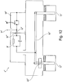
- FIG. 12 A further embodiment of an installation part 4 'with coupling in of at least one resistance measuring device 5' is Fig. 12 refer to.
- the design of the Fig. 12 is in its basic arrangement of the formation of the direct current feeder the design of an installation part of the Fig. 10 comparable.
- Fig. 12 On the design of the Fig. 10 in the design of the first contact element 12 'and the second contact element 13'.
- the first contact element 12 'and the second contact element 13' are in the Fig. 12 designed to be removed as sockets.
- the capacitor 10 ' is designed to improve the capacitive separation of the first contact element 12' and the second contact element 13 'as a ceramic plate.
- the ceramic plate shown for example, has a capacity of at least 500 microfarads.
- the in the Fig. 12 The embodiment shown corresponds in its design, for example, to a stirrup plug, as is used in many cases at the start of a feed line of a transmitting antenna system in which the resistance measuring device is integrated.
Landscapes
- Engineering & Computer Science (AREA)
- Computer Networks & Wireless Communication (AREA)
- Signal Processing (AREA)
- Measurement Of Resistance Or Impedance (AREA)
- Arrangements For Transmission Of Measured Signals (AREA)
Claims (16)
- Dispositif de surveillance (4') destiné à une installation d'antenne émettrice (1'), comportant un trajet de transport de puissance (2') doté d'un conducteur intérieur et d'un conducteur extérieur, avec- un conducteur de saisie de signal de mesure pour raccordement galvanique au conducteur intérieur et- une unité de contrôle et de commande dotée d'une entrée reliée au conducteur de saisie de signal de mesure et d'une sortie, et- un interrupteur destiné à interrompre l'alimentation du signal d'émission de l'installation d'antenne émettrice,- dans lequel l'interrupteur peut être ouvert ou fermé par le biais d'un signal de sortie de l'unité de contrôle et de commande et- dans lequel l'unité de contrôle et de commande compare à une valeur seuil une valeur de mesure d'un signal de mesure fourni par le biais du conducteur de saisie de signal de mesure dans un intervalle de fréquence entre 0 et 60 kHz pouvant être prédéfini et ensuite, lorsque la valeur de mesure dans l'intervalle de fréquence spécifié est supérieure à la valeur seuil, délivre à sa sortie un signal d'ouverture ouvrant l'interrupteur au moins temporairement.
- Dispositif de surveillance (4') selon la revendication 1, caractérisé en ce que l'unité de contrôle et de commande compare à une valeur seuil une valeur de mesure d'un signal de mesure pouvant être fourni par le biais du conducteur de saisie de signal de mesure dans un intervalle de fréquence entre 0 et 20 kHz pouvant être prédéfini et ensuite, lorsque la valeur de mesure dans l'intervalle de fréquence spécifié est supérieure à la valeur seuil, délivre à sa sortie un signal d'ouverture ouvrant l'interrupteur au moins temporairement.
- Dispositif de surveillance (4') selon la revendication 1 ou 2, caractérisé en ce que la valeur de mesure comparée à la valeur seuil représente une valeur d'intensité du signal de mesure.
- Dispositif de surveillance (4') selon l'une des revendications 1 à 3, caractérisé en ce que l'unité de contrôle et de commande délivre automatiquement un signal de fermeture pour l'interrupteur après un signal d'ouverture et vérifie si la valeur de mesure dans l'intervalle de fréquence spécifié est supérieure à la valeur seuil, après quoi, si c'est le cas, l'unité de contrôle et de commande délivre de nouveau un signal d'ouverture afin d'ouvrir l'interrupteur.
- Dispositif de surveillance (4') selon l'une des revendications 1 à 4, caractérisé en ce que l'unité de contrôle et de commande émet de manière alternée des signaux de fermeture et d'ouverture pour l'interrupteur, à savoir tant que la valeur de mesure dans l'intervalle de fréquence spécifié est supérieure à la valeur seuil, dans lequel après un nombre prédéfini de répétitions d'émissions alternées de signaux de fermeture et d'ouverture, l'interrupteur reste ouvert.
- Dispositif de surveillance (4') selon l'une des revendications 1 à 5, caractérisé en ce que le conducteur de saisie de signal de mesure est un conducteur λ/4, dans lequel λ est la longueur d'onde de la fréquence porteuse du signal d'émission de l'installation d'antenne émettrice.
- Dispositif de surveillance (4') selon l'une des revendications 1 à 6, caractérisé en ce que pour une installation d'antenne émettrice dotée d'une antenne ouverte galvaniquement, l'unité de contrôle et de commande imprime un courant de mesure dans le conducteur intérieur par le biais du conducteur de saisie de signal de mesure, et mesure la résistance entre le conducteur extérieur et le conducteur intérieur du trajet de puissance (2') et, lorsque la résistance mesurée est inférieure à une résistance minimale pouvant être prédéfinie, fournit à sa sortie un signal d'ouverture pour l'interrupteur et/ou fournit à sa sortie un signal d'affichage destiné à l'affichage optique de la résistance mesurée ou d'une valeur caractérisant celle-ci.
- Dispositif de surveillance (4') selon l'une des revendications 1 à 7, caractérisé en ce que pour une installation d'antenne émettrice (1') dotée d'une antenne fermée galvaniquement, l'unité de contrôle et de commande effectue par le biais du conducteur de saisie de signal de mesure une mesure de la résistance du circuit électrique formé par le conducteur extérieur, le conducteur intérieur et l'antenne et, lorsque la résistance mesurée est supérieure à une résistance maximale autorisée pouvant être prédéfinie, fournit à sa sortie un signal d'ouverture pour l'interrupteur et/ou fournit un signal d'affichage destiné à l'affichage optique de la résistance mesurée ou d'une valeur caractérisant celle-ci.
- Dispositif de surveillance (4') selon l'une des revendications 1 à 8, caractérisé en ce que le conducteur de saisie de signal de mesure peut être relié galvaniquement au conducteur intérieur d'un connecteur en pont de l'installation d'antenne émettrice (1').
- Procédé de surveillance d'une installation d'antenne émettrice (1'), comportant un trajet de transport de puissance (2') doté d'un conducteur intérieur et d'un conducteur extérieur,- dans lequel, lors du procédé, un signal de mesure est saisi depuis le conducteur intérieur par le biais d'un conducteur de saisie de signal de mesure relié à celui-ci, et- une valeur de mesure du signal de mesure dans un intervalle de fréquence entre 0 et 60 kHz pouvant être prédéfini est comparée à une valeur seuil et- ensuite, si la valeur de mesure dans l'intervalle de fréquence spécifié est supérieure à la valeur seuil, la fourniture d'un signal d'émission à l'installation d'antenne d'émission (1') est interrompue au moins temporairement.
- Procédé selon la revendication 10, caractérisé en ce qu'une valeur de mesure du signal de mesure dans un intervalle de fréquence entre 0 et 20 kHz pouvant être prédéfini est comparée à une valeur seuil et ensuite, si la valeur de mesure dans l'intervalle de fréquence spécifié est supérieure à la valeur seuil, la fourniture d'un signal d'émission à l'installation d'antenne d'émission (1') est interrompue au moins temporairement.
- Procédé selon la revendication 10 ou 11, caractérisé en ce qu'un conducteur λ/4 est utilisé comme conducteur de saisie de signal de mesure, dans lequel λ est la longueur d'onde de la fréquence porteuse du signal d'émission de l'installation d'antenne émettrice (1').
- Procédé selon l'une des revendications 10 à 12, caractérisé en ce que pour une installation d'antenne émettrice (1') dotée d'une antenne ouverte galvaniquement, un courant de mesure est imprimé dans le conducteur intérieur par le biais du conducteur de saisie de signal de mesure, et la résistance entre le conducteur extérieur et le conducteur intérieur du trajet de puissance (2') est mesurée et, lorsque la résistance mesurée est inférieure à une résistance minimale pouvant être prédéfinie, la fourniture du signal d'émission à l'installation d'antenne émettrice (1') est interrompue au moins temporairement et/ou un signal d'affichage destiné à l'affichage optique de la résistance mesurée ou d'une valeur caractérisant celle-ci est émis.
- Procédé selon l'une des revendications 10 à 13, caractérisé en ce que pour une installation d'antenne émettrice (1') dotée d'une antenne fermée galvaniquement, une mesure de la résistance du circuit électrique formé par le conducteur extérieur, le conducteur intérieur et l'antenne est effectuée par le biais du conducteur de saisie de signal de mesure et, lorsque la résistance mesurée est supérieure à une résistance maximale autorisée pouvant être prédéfinie, un signal d'ouverture pour l'interrupteur est émis à sa sortie et/ou un signal d'affichage destiné à l'affichage optique de la résistance mesurée ou d'une valeur caractérisant celle-ci est émis.
- Procédé selon l'une des revendications 10 à 14, caractérisé en ce que le conducteur de saisie de signal de mesure est relié galvaniquement au conducteur intérieur d'un connecteur en pont de l'installation d'antenne émettrice (1').
- Installation d'antenne émettrice comportant un trajet de transport de puissance (2') doté d'un conducteur intérieur et d'un conducteur extérieur et d'un dispositif de surveillance (4') selon l'une des revendications 1 à 9.
Applications Claiming Priority (2)
| Application Number | Priority Date | Filing Date | Title |
|---|---|---|---|
| DE102014224037 | 2014-11-25 | ||
| PCT/EP2015/070770 WO2016082953A1 (fr) | 2014-11-25 | 2015-09-10 | Dispositif de surveillance pour une installation d'antennes d'émission et procédé de surveillance d'une installation d'antenne d'émission |
Publications (2)
| Publication Number | Publication Date |
|---|---|
| EP3224902A1 EP3224902A1 (fr) | 2017-10-04 |
| EP3224902B1 true EP3224902B1 (fr) | 2020-03-18 |
Family
ID=54151258
Family Applications (1)
| Application Number | Title | Priority Date | Filing Date |
|---|---|---|---|
| EP15767114.0A Active EP3224902B1 (fr) | 2014-11-25 | 2015-09-10 | Dispositif de surveillance pour une installation d'antennes d'émission et procédé de surveillance d'une installation d'antenne d'émission |
Country Status (2)
| Country | Link |
|---|---|
| EP (1) | EP3224902B1 (fr) |
| WO (1) | WO2016082953A1 (fr) |
Family Cites Families (4)
| Publication number | Priority date | Publication date | Assignee | Title |
|---|---|---|---|---|
| DE102012110687A1 (de) * | 2012-08-27 | 2014-05-15 | Newtos Ag | Verfahren zur Lichtbogenerkennung in Photovoltaikanlagen |
| US9438027B2 (en) * | 2013-03-15 | 2016-09-06 | General Electric Company | Systems and methods for power interruption |
| DE102013014476A1 (de) * | 2013-09-02 | 2015-03-05 | Media Broadcast Gmbh | Sendeantennenanlage mit einer Überwachung einer elektrischen Leitungseigenschaft und Einbauteil mit einer Einkopplung einer Widerstandsmesseinrichtung |
| RU2015103516A (ru) * | 2014-02-06 | 2016-08-20 | Институт Фюр Рундфунктехник ГмбХ | Устройство для наблюдения за функционированием системы передающих антенн, способ наблюдения и устройство обнаружения, которое можно применять в устройстве для наблюдения |
-
2015
- 2015-09-10 EP EP15767114.0A patent/EP3224902B1/fr active Active
- 2015-09-10 WO PCT/EP2015/070770 patent/WO2016082953A1/fr not_active Ceased
Non-Patent Citations (1)
| Title |
|---|
| None * |
Also Published As
| Publication number | Publication date |
|---|---|
| WO2016082953A1 (fr) | 2016-06-02 |
| EP3224902A1 (fr) | 2017-10-04 |
Similar Documents
| Publication | Publication Date | Title |
|---|---|---|
| EP2737330B1 (fr) | Procédé d'adaptation d'un capteur d'arc électrique | |
| EP3923010B1 (fr) | Prise de courant de sécurité et procédé de localisation des défauts d'isolation dans un système d'alimentation électrique non mis à la masse avec surveillance d'isolation | |
| DE102012109749A1 (de) | Verfahren und Vorrichtung zum Erkennen eines Lichtbogens in einem Gleichstromkreis | |
| EP3139188B1 (fr) | Procédé et dispositif de recherche d'erreur d'isolation comprenant une détermination adaptative de courant de test | |
| DE102008063682A1 (de) | Einheit zur Überwachung und/oder Signalisierung/Visualisierung von Betriebsgrößen einer gasisolierten Schaltanlage | |
| EP3861359B1 (fr) | Procédé pour déterminer un court-circuit à l'apparition d'un arc électrique sur un conducteur électrique | |
| DE102011079935A1 (de) | Überwachungsvorrichtung für eine Kabelmuffe | |
| AT508192A1 (de) | Überwachungsvorrichtung | |
| EP3273459A1 (fr) | Dispositif et procede de surveillance d'une unite d'interruption dans un reseau d'alimentation en energie electrique et station de distribution comprenant une unite d'interruption surveillee | |
| DE112011100449B4 (de) | Verfahren zum Überprüfen eines Kurzschluss-Schutzsystems in einer Abzweigleitung sowie Diagnoseeinrichtung zum Durchführen des Verfahrens | |
| WO2005060063A1 (fr) | Procede et dispositif de detection d'une source de bruit a bande large dans un reseau de distribution a tension continue | |
| EP3655786A1 (fr) | Procédé et système d'identification de décharges partielles dans une ressource électrique | |
| EP3245694B1 (fr) | Procédé de catégorisation d'un arc électrique ou de détection d'un arc électrique parasite | |
| EP3224902B1 (fr) | Dispositif de surveillance pour une installation d'antennes d'émission et procédé de surveillance d'une installation d'antenne d'émission | |
| EP2462670A1 (fr) | Configuration d'installation électrique | |
| EP3269015B1 (fr) | Procédé de détermination d'état et de localisation de défauts sur des dérivations isolées installées dans un système de protection extérieure contre la foudre | |
| WO2004102760A1 (fr) | Procede et dispositif de detection d'arcs electriques perturbateurs | |
| DE102007008263B4 (de) | Überwachungsvorrichtung für eine Zweidraht-Leitung, Gefahrenmeldesystem mit der Überwachungsvorrichtung | |
| DE4026428A1 (de) | Vorrichtung zum bestimmen sich verschlechternder eigenschaften einer hochspannungsleitung | |
| EP2954757B1 (fr) | Installation d'éclairage et procédé de détermination de l'état de fonctionnement d'une installation d'éclairage | |
| DE112020006177T5 (de) | Verfahren, Vorrichtung und Anordnung zur Überwachung von elektrischen Wechselstromgeräten | |
| EP2848950A1 (fr) | Installation d'antenne radio avec la surveillance d'une propriété électrique d'un câble et une partie de montée à coupler une unité de mesure de résistance. | |
| DE102022117038B3 (de) | Verfahren zum Überwachen eines Schutzleiters eines Versorgungsnetzes und eine entsprechend konfigurierte Überwachungseinrichtung | |
| DE202014011102U1 (de) | Elektrische Schaltvorrichtung mit einem eingebauten Verbindungssystem zum Verbinden einer Messungseinrichtung und Einspeisen und Erfassen von niederfrequenten und hochfrequenten Signalen | |
| DE102020129825A1 (de) | Verfahren zur Vermeidung einer Kollision bei der Messung der Schleifenimpedanz durch mehrere Teilnehmer |
Legal Events
| Date | Code | Title | Description |
|---|---|---|---|
| STAA | Information on the status of an ep patent application or granted ep patent |
Free format text: STATUS: THE INTERNATIONAL PUBLICATION HAS BEEN MADE |
|
| PUAI | Public reference made under article 153(3) epc to a published international application that has entered the european phase |
Free format text: ORIGINAL CODE: 0009012 |
|
| STAA | Information on the status of an ep patent application or granted ep patent |
Free format text: STATUS: REQUEST FOR EXAMINATION WAS MADE |
|
| 17P | Request for examination filed |
Effective date: 20170531 |
|
| AK | Designated contracting states |
Kind code of ref document: A1 Designated state(s): AL AT BE BG CH CY CZ DE DK EE ES FI FR GB GR HR HU IE IS IT LI LT LU LV MC MK MT NL NO PL PT RO RS SE SI SK SM TR |
|
| AX | Request for extension of the european patent |
Extension state: BA ME |
|
| DAV | Request for validation of the european patent (deleted) | ||
| DAX | Request for extension of the european patent (deleted) | ||
| GRAP | Despatch of communication of intention to grant a patent |
Free format text: ORIGINAL CODE: EPIDOSNIGR1 |
|
| STAA | Information on the status of an ep patent application or granted ep patent |
Free format text: STATUS: GRANT OF PATENT IS INTENDED |
|
| INTG | Intention to grant announced |
Effective date: 20180809 |
|
| GRAJ | Information related to disapproval of communication of intention to grant by the applicant or resumption of examination proceedings by the epo deleted |
Free format text: ORIGINAL CODE: EPIDOSDIGR1 |
|
| STAA | Information on the status of an ep patent application or granted ep patent |
Free format text: STATUS: REQUEST FOR EXAMINATION WAS MADE |
|
| STAA | Information on the status of an ep patent application or granted ep patent |
Free format text: STATUS: EXAMINATION IS IN PROGRESS |
|
| INTC | Intention to grant announced (deleted) | ||
| 17Q | First examination report despatched |
Effective date: 20190115 |
|
| GRAS | Grant fee paid |
Free format text: ORIGINAL CODE: EPIDOSNIGR3 |
|
| STAA | Information on the status of an ep patent application or granted ep patent |
Free format text: STATUS: GRANT OF PATENT IS INTENDED |
|
| GRAP | Despatch of communication of intention to grant a patent |
Free format text: ORIGINAL CODE: EPIDOSNIGR1 |
|
| INTG | Intention to grant announced |
Effective date: 20191211 |
|
| GRAA | (expected) grant |
Free format text: ORIGINAL CODE: 0009210 |
|
| STAA | Information on the status of an ep patent application or granted ep patent |
Free format text: STATUS: THE PATENT HAS BEEN GRANTED |
|
| AK | Designated contracting states |
Kind code of ref document: B1 Designated state(s): AL AT BE BG CH CY CZ DE DK EE ES FI FR GB GR HR HU IE IS IT LI LT LU LV MC MK MT NL NO PL PT RO RS SE SI SK SM TR |
|
| REG | Reference to a national code |
Ref country code: GB Ref legal event code: FG4D Free format text: NOT ENGLISH |
|
| REG | Reference to a national code |
Ref country code: DE Ref legal event code: R096 Ref document number: 502015012058 Country of ref document: DE |
|
| REG | Reference to a national code |
Ref country code: AT Ref legal event code: REF Ref document number: 1247010 Country of ref document: AT Kind code of ref document: T Effective date: 20200415 Ref country code: IE Ref legal event code: FG4D Free format text: LANGUAGE OF EP DOCUMENT: GERMAN |
|
| PG25 | Lapsed in a contracting state [announced via postgrant information from national office to epo] |
Ref country code: RS Free format text: LAPSE BECAUSE OF FAILURE TO SUBMIT A TRANSLATION OF THE DESCRIPTION OR TO PAY THE FEE WITHIN THE PRESCRIBED TIME-LIMIT Effective date: 20200318 Ref country code: NO Free format text: LAPSE BECAUSE OF FAILURE TO SUBMIT A TRANSLATION OF THE DESCRIPTION OR TO PAY THE FEE WITHIN THE PRESCRIBED TIME-LIMIT Effective date: 20200618 Ref country code: FI Free format text: LAPSE BECAUSE OF FAILURE TO SUBMIT A TRANSLATION OF THE DESCRIPTION OR TO PAY THE FEE WITHIN THE PRESCRIBED TIME-LIMIT Effective date: 20200318 |
|
| REG | Reference to a national code |
Ref country code: NL Ref legal event code: MP Effective date: 20200318 |
|
| PG25 | Lapsed in a contracting state [announced via postgrant information from national office to epo] |
Ref country code: SE Free format text: LAPSE BECAUSE OF FAILURE TO SUBMIT A TRANSLATION OF THE DESCRIPTION OR TO PAY THE FEE WITHIN THE PRESCRIBED TIME-LIMIT Effective date: 20200318 Ref country code: HR Free format text: LAPSE BECAUSE OF FAILURE TO SUBMIT A TRANSLATION OF THE DESCRIPTION OR TO PAY THE FEE WITHIN THE PRESCRIBED TIME-LIMIT Effective date: 20200318 Ref country code: LV Free format text: LAPSE BECAUSE OF FAILURE TO SUBMIT A TRANSLATION OF THE DESCRIPTION OR TO PAY THE FEE WITHIN THE PRESCRIBED TIME-LIMIT Effective date: 20200318 Ref country code: GR Free format text: LAPSE BECAUSE OF FAILURE TO SUBMIT A TRANSLATION OF THE DESCRIPTION OR TO PAY THE FEE WITHIN THE PRESCRIBED TIME-LIMIT Effective date: 20200619 Ref country code: BG Free format text: LAPSE BECAUSE OF FAILURE TO SUBMIT A TRANSLATION OF THE DESCRIPTION OR TO PAY THE FEE WITHIN THE PRESCRIBED TIME-LIMIT Effective date: 20200618 |
|
| REG | Reference to a national code |
Ref country code: LT Ref legal event code: MG4D |
|
| PG25 | Lapsed in a contracting state [announced via postgrant information from national office to epo] |
Ref country code: NL Free format text: LAPSE BECAUSE OF FAILURE TO SUBMIT A TRANSLATION OF THE DESCRIPTION OR TO PAY THE FEE WITHIN THE PRESCRIBED TIME-LIMIT Effective date: 20200318 |
|
| PG25 | Lapsed in a contracting state [announced via postgrant information from national office to epo] |
Ref country code: SM Free format text: LAPSE BECAUSE OF FAILURE TO SUBMIT A TRANSLATION OF THE DESCRIPTION OR TO PAY THE FEE WITHIN THE PRESCRIBED TIME-LIMIT Effective date: 20200318 Ref country code: EE Free format text: LAPSE BECAUSE OF FAILURE TO SUBMIT A TRANSLATION OF THE DESCRIPTION OR TO PAY THE FEE WITHIN THE PRESCRIBED TIME-LIMIT Effective date: 20200318 Ref country code: SK Free format text: LAPSE BECAUSE OF FAILURE TO SUBMIT A TRANSLATION OF THE DESCRIPTION OR TO PAY THE FEE WITHIN THE PRESCRIBED TIME-LIMIT Effective date: 20200318 Ref country code: CZ Free format text: LAPSE BECAUSE OF FAILURE TO SUBMIT A TRANSLATION OF THE DESCRIPTION OR TO PAY THE FEE WITHIN THE PRESCRIBED TIME-LIMIT Effective date: 20200318 Ref country code: RO Free format text: LAPSE BECAUSE OF FAILURE TO SUBMIT A TRANSLATION OF THE DESCRIPTION OR TO PAY THE FEE WITHIN THE PRESCRIBED TIME-LIMIT Effective date: 20200318 Ref country code: LT Free format text: LAPSE BECAUSE OF FAILURE TO SUBMIT A TRANSLATION OF THE DESCRIPTION OR TO PAY THE FEE WITHIN THE PRESCRIBED TIME-LIMIT Effective date: 20200318 Ref country code: PT Free format text: LAPSE BECAUSE OF FAILURE TO SUBMIT A TRANSLATION OF THE DESCRIPTION OR TO PAY THE FEE WITHIN THE PRESCRIBED TIME-LIMIT Effective date: 20200812 Ref country code: IS Free format text: LAPSE BECAUSE OF FAILURE TO SUBMIT A TRANSLATION OF THE DESCRIPTION OR TO PAY THE FEE WITHIN THE PRESCRIBED TIME-LIMIT Effective date: 20200718 |
|
| REG | Reference to a national code |
Ref country code: DE Ref legal event code: R097 Ref document number: 502015012058 Country of ref document: DE |
|
| PLBE | No opposition filed within time limit |
Free format text: ORIGINAL CODE: 0009261 |
|
| STAA | Information on the status of an ep patent application or granted ep patent |
Free format text: STATUS: NO OPPOSITION FILED WITHIN TIME LIMIT |
|
| PG25 | Lapsed in a contracting state [announced via postgrant information from national office to epo] |
Ref country code: ES Free format text: LAPSE BECAUSE OF FAILURE TO SUBMIT A TRANSLATION OF THE DESCRIPTION OR TO PAY THE FEE WITHIN THE PRESCRIBED TIME-LIMIT Effective date: 20200318 Ref country code: DK Free format text: LAPSE BECAUSE OF FAILURE TO SUBMIT A TRANSLATION OF THE DESCRIPTION OR TO PAY THE FEE WITHIN THE PRESCRIBED TIME-LIMIT Effective date: 20200318 Ref country code: IT Free format text: LAPSE BECAUSE OF FAILURE TO SUBMIT A TRANSLATION OF THE DESCRIPTION OR TO PAY THE FEE WITHIN THE PRESCRIBED TIME-LIMIT Effective date: 20200318 |
|
| 26N | No opposition filed |
Effective date: 20201221 |
|
| PG25 | Lapsed in a contracting state [announced via postgrant information from national office to epo] |
Ref country code: PL Free format text: LAPSE BECAUSE OF FAILURE TO SUBMIT A TRANSLATION OF THE DESCRIPTION OR TO PAY THE FEE WITHIN THE PRESCRIBED TIME-LIMIT Effective date: 20200318 |
|
| REG | Reference to a national code |
Ref country code: CH Ref legal event code: PL |
|
| GBPC | Gb: european patent ceased through non-payment of renewal fee |
Effective date: 20200910 |
|
| PG25 | Lapsed in a contracting state [announced via postgrant information from national office to epo] |
Ref country code: SI Free format text: LAPSE BECAUSE OF FAILURE TO SUBMIT A TRANSLATION OF THE DESCRIPTION OR TO PAY THE FEE WITHIN THE PRESCRIBED TIME-LIMIT Effective date: 20200318 |
|
| REG | Reference to a national code |
Ref country code: BE Ref legal event code: MM Effective date: 20200930 |
|
| PG25 | Lapsed in a contracting state [announced via postgrant information from national office to epo] |
Ref country code: LU Free format text: LAPSE BECAUSE OF NON-PAYMENT OF DUE FEES Effective date: 20200910 |
|
| PG25 | Lapsed in a contracting state [announced via postgrant information from national office to epo] |
Ref country code: FR Free format text: LAPSE BECAUSE OF NON-PAYMENT OF DUE FEES Effective date: 20200930 |
|
| PG25 | Lapsed in a contracting state [announced via postgrant information from national office to epo] |
Ref country code: BE Free format text: LAPSE BECAUSE OF NON-PAYMENT OF DUE FEES Effective date: 20200930 Ref country code: CH Free format text: LAPSE BECAUSE OF NON-PAYMENT OF DUE FEES Effective date: 20200930 Ref country code: IE Free format text: LAPSE BECAUSE OF NON-PAYMENT OF DUE FEES Effective date: 20200910 Ref country code: LI Free format text: LAPSE BECAUSE OF NON-PAYMENT OF DUE FEES Effective date: 20200930 Ref country code: GB Free format text: LAPSE BECAUSE OF NON-PAYMENT OF DUE FEES Effective date: 20200910 |
|
| REG | Reference to a national code |
Ref country code: AT Ref legal event code: MM01 Ref document number: 1247010 Country of ref document: AT Kind code of ref document: T Effective date: 20200910 |
|
| PG25 | Lapsed in a contracting state [announced via postgrant information from national office to epo] |
Ref country code: AT Free format text: LAPSE BECAUSE OF NON-PAYMENT OF DUE FEES Effective date: 20200910 |
|
| PG25 | Lapsed in a contracting state [announced via postgrant information from national office to epo] |
Ref country code: TR Free format text: LAPSE BECAUSE OF FAILURE TO SUBMIT A TRANSLATION OF THE DESCRIPTION OR TO PAY THE FEE WITHIN THE PRESCRIBED TIME-LIMIT Effective date: 20200318 Ref country code: MT Free format text: LAPSE BECAUSE OF FAILURE TO SUBMIT A TRANSLATION OF THE DESCRIPTION OR TO PAY THE FEE WITHIN THE PRESCRIBED TIME-LIMIT Effective date: 20200318 Ref country code: CY Free format text: LAPSE BECAUSE OF FAILURE TO SUBMIT A TRANSLATION OF THE DESCRIPTION OR TO PAY THE FEE WITHIN THE PRESCRIBED TIME-LIMIT Effective date: 20200318 |
|
| PG25 | Lapsed in a contracting state [announced via postgrant information from national office to epo] |
Ref country code: MK Free format text: LAPSE BECAUSE OF FAILURE TO SUBMIT A TRANSLATION OF THE DESCRIPTION OR TO PAY THE FEE WITHIN THE PRESCRIBED TIME-LIMIT Effective date: 20200318 Ref country code: MC Free format text: LAPSE BECAUSE OF FAILURE TO SUBMIT A TRANSLATION OF THE DESCRIPTION OR TO PAY THE FEE WITHIN THE PRESCRIBED TIME-LIMIT Effective date: 20200318 Ref country code: AL Free format text: LAPSE BECAUSE OF FAILURE TO SUBMIT A TRANSLATION OF THE DESCRIPTION OR TO PAY THE FEE WITHIN THE PRESCRIBED TIME-LIMIT Effective date: 20200318 |
|
| P01 | Opt-out of the competence of the unified patent court (upc) registered |
Effective date: 20230524 |
|
| PGFP | Annual fee paid to national office [announced via postgrant information from national office to epo] |
Ref country code: DE Payment date: 20250717 Year of fee payment: 11 |