EP2851300A1 - Verkleidungsvorrichtung für das gesamte Antriebssystem eines Luftfahrzeugs, die ein Innenfach mit einem Ventilator enthält - Google Patents
Verkleidungsvorrichtung für das gesamte Antriebssystem eines Luftfahrzeugs, die ein Innenfach mit einem Ventilator enthält Download PDFInfo
- Publication number
- EP2851300A1 EP2851300A1 EP20140184962 EP14184962A EP2851300A1 EP 2851300 A1 EP2851300 A1 EP 2851300A1 EP 20140184962 EP20140184962 EP 20140184962 EP 14184962 A EP14184962 A EP 14184962A EP 2851300 A1 EP2851300 A1 EP 2851300A1
- Authority
- EP
- European Patent Office
- Prior art keywords
- gear
- propeller
- turbomachine
- fan
- rotor
- Prior art date
- Legal status (The legal status is an assumption and is not a legal conclusion. Google has not performed a legal analysis and makes no representation as to the accuracy of the status listed.)
- Granted
Links
Images



Classifications
-
- F—MECHANICAL ENGINEERING; LIGHTING; HEATING; WEAPONS; BLASTING
- F02—COMBUSTION ENGINES; HOT-GAS OR COMBUSTION-PRODUCT ENGINE PLANTS
- F02C—GAS-TURBINE PLANTS; AIR INTAKES FOR JET-PROPULSION PLANTS; CONTROLLING FUEL SUPPLY IN AIR-BREATHING JET-PROPULSION PLANTS
- F02C7/00—Features, components parts, details or accessories, not provided for in, or of interest apart form groups F02C1/00 - F02C6/00; Air intakes for jet-propulsion plants
- F02C7/12—Cooling of plants
- F02C7/16—Cooling of plants characterised by cooling medium
- F02C7/18—Cooling of plants characterised by cooling medium the medium being gaseous, e.g. air
-
- B—PERFORMING OPERATIONS; TRANSPORTING
- B64—AIRCRAFT; AVIATION; COSMONAUTICS
- B64D—EQUIPMENT FOR FITTING IN OR TO AIRCRAFT; FLIGHT SUITS; PARACHUTES; ARRANGEMENT OR MOUNTING OF POWER PLANTS OR PROPULSION TRANSMISSIONS IN AIRCRAFT
- B64D33/00—Arrangement in aircraft of power plant parts or auxiliaries not otherwise provided for
- B64D33/08—Arrangement in aircraft of power plant parts or auxiliaries not otherwise provided for of power plant cooling systems
-
- F—MECHANICAL ENGINEERING; LIGHTING; HEATING; WEAPONS; BLASTING
- F02—COMBUSTION ENGINES; HOT-GAS OR COMBUSTION-PRODUCT ENGINE PLANTS
- F02C—GAS-TURBINE PLANTS; AIR INTAKES FOR JET-PROPULSION PLANTS; CONTROLLING FUEL SUPPLY IN AIR-BREATHING JET-PROPULSION PLANTS
- F02C7/00—Features, components parts, details or accessories, not provided for in, or of interest apart form groups F02C1/00 - F02C6/00; Air intakes for jet-propulsion plants
- F02C7/32—Arrangement, mounting, or driving, of auxiliaries
-
- B—PERFORMING OPERATIONS; TRANSPORTING
- B64—AIRCRAFT; AVIATION; COSMONAUTICS
- B64D—EQUIPMENT FOR FITTING IN OR TO AIRCRAFT; FLIGHT SUITS; PARACHUTES; ARRANGEMENT OR MOUNTING OF POWER PLANTS OR PROPULSION TRANSMISSIONS IN AIRCRAFT
- B64D33/00—Arrangement in aircraft of power plant parts or auxiliaries not otherwise provided for
- B64D33/02—Arrangement in aircraft of power plant parts or auxiliaries not otherwise provided for of combustion air intakes
- B64D2033/024—Arrangement in aircraft of power plant parts or auxiliaries not otherwise provided for of combustion air intakes comprising cooling means
-
- B—PERFORMING OPERATIONS; TRANSPORTING
- B64—AIRCRAFT; AVIATION; COSMONAUTICS
- B64D—EQUIPMENT FOR FITTING IN OR TO AIRCRAFT; FLIGHT SUITS; PARACHUTES; ARRANGEMENT OR MOUNTING OF POWER PLANTS OR PROPULSION TRANSMISSIONS IN AIRCRAFT
- B64D33/00—Arrangement in aircraft of power plant parts or auxiliaries not otherwise provided for
- B64D33/02—Arrangement in aircraft of power plant parts or auxiliaries not otherwise provided for of combustion air intakes
- B64D2033/0266—Arrangement in aircraft of power plant parts or auxiliaries not otherwise provided for of combustion air intakes specially adapted for particular type of power plants
- B64D2033/0286—Arrangement in aircraft of power plant parts or auxiliaries not otherwise provided for of combustion air intakes specially adapted for particular type of power plants for turbofan engines
-
- F—MECHANICAL ENGINEERING; LIGHTING; HEATING; WEAPONS; BLASTING
- F05—INDEXING SCHEMES RELATING TO ENGINES OR PUMPS IN VARIOUS SUBCLASSES OF CLASSES F01-F04
- F05D—INDEXING SCHEME FOR ASPECTS RELATING TO NON-POSITIVE-DISPLACEMENT MACHINES OR ENGINES, GAS-TURBINES OR JET-PROPULSION PLANTS
- F05D2260/00—Function
- F05D2260/60—Fluid transfer
- F05D2260/608—Aeration, ventilation, dehumidification or moisture removal of closed spaces
-
- Y—GENERAL TAGGING OF NEW TECHNOLOGICAL DEVELOPMENTS; GENERAL TAGGING OF CROSS-SECTIONAL TECHNOLOGIES SPANNING OVER SEVERAL SECTIONS OF THE IPC; TECHNICAL SUBJECTS COVERED BY FORMER USPC CROSS-REFERENCE ART COLLECTIONS [XRACs] AND DIGESTS
- Y02—TECHNOLOGIES OR APPLICATIONS FOR MITIGATION OR ADAPTATION AGAINST CLIMATE CHANGE
- Y02T—CLIMATE CHANGE MITIGATION TECHNOLOGIES RELATED TO TRANSPORTATION
- Y02T50/00—Aeronautics or air transport
- Y02T50/60—Efficient propulsion technologies, e.g. for aircraft
Definitions
- the present invention relates to an aircraft propulsion unit comprising at least one fairing device, and more particularly to the cooling of a compartment defined inside such a fairing device.
- the invention is equally applicable to propulsion assemblies comprising a turbojet and to those comprising a turboprop or to those comprising a turbojet engine with unducted propellers, of the type also called "Open Rotor".
- the fairing device may be of the type externally defining the secondary flow channel of a turbofan engine, or of the type separating the secondary flow channel and the core of such a turbofan engine. , or else of the type externally defining a turboprop or a turbojet engine with unducted propellers.
- the invention also relates to an aircraft equipped with such a propulsion unit, as well as a method of ventilating an interior compartment in a fairing device of such a propulsion unit.
- the outer fairing device which surrounds the turbojet engine generally comprises an annular wall or outer casing and an annular wall or inner casing.
- the outer annular wall forms an outer fairing along which the relative wind flows in flight, while the inner annular wall is intended to channel a flow of air supplying the turbomachine.
- the flow of air channelized by the inner annular wall is the secondary flow propelled by the fan and flowing downstream around the heart of the turbojet engine.
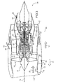
- the figure 1 is a partial view in axial section of an aircraft propulsion assembly 10 of a known type, comprising a turbofan engine 12 and an outer fairing device 14 surrounding this turbojet engine.
- the outer annular wall 16 cares the propulsion assembly 10 with respect to the relative wind 18 while the inner annular wall 20 channels, upstream, the air flow 22 penetrating the assembly propellant, and downstream, the secondary flow 24 from said flow 22 and flowing around the core 26 of the turbojet engine 12.
- upstream and downstream directions are defined with respect to the overall direction of the gas flow in the turbomachine, and the terms “before” and “back” are to be considered in relation to to a direction F of advancement of the aircraft under the effect of the thrust exerted by the turbojet engine 12, this direction being parallel to a longitudinal axis 72 of the turbojet engine.
- the outer annular walls 16 and inner 20 delimit between them an inner compartment 28 of the outer fairing device 14, also called “fan compartment” due to its location at the right of the fan 30, between an air inlet sleeve 32 and a thrust reverser 34.
- the outer wall 16, an upstream portion of the inner wall 20 corresponding to the air inlet sleeve 32, and a downstream portion of the inner wall 20 corresponding to the thrust reverser 34, are part of a nacelle of the propulsion unit 10.
- an intermediate portion of the inner wall 20, which defines the inner compartment 28, is part of an intermediate casing 35 integral with the core 26 of the turbojet engine.
- the inner compartment 28 usually contains an accessory control box 36, also called AGB ("Accessory Gear Box "), for mechanically connecting a rotor 38 of the turbomachine to one or more accessories, such as a starter.
- AGB Accessory Gear Box
- the rotor 38 concerned is a rotor of high pressure compressor and is connected to the AGB 36 via a deflection shaft 40 extending from the core 26 of the turbojet engine into the inner compartment 28.
- the inner compartment 28 is generally used to house one or more systems, such as a control unit of the engine, also called ECU ("Engine Control Unit"), none of these systems being visible in the section plane of the figure 1 .
- ECU Engine Control Unit
- the safety standards require that the concentration of air in flammable vapors within the interior compartment 28 does not exceed a predefined maximum level, so that the interior compartment must be ventilated. By “ventilation” it is necessary to understand the regular renewal of the air within the interior compartment 28.
- the outer fairing device 14 usually comprises an air intake port 42 and an air exhaust port 43 formed in the outer wall 16.
- the two orifices 42 and 43 are generally diametrically opposed as on the figure 1 .
- the air intake port 42 is generally arranged near the upstream end of the interior compartment 28 while the exhaust port is typically arranged near the downstream end of the interior compartment 28. .
- the outer wall 16 is generally shaped to form a dynamic air intake.
- the upstream edge 44 of the air intake orifice 42 is for example curved towards the inside of the inner compartment 28 as on the figure 1 to form an air intake of the type commonly called "NACA", such as to promote the penetration of the boundary air layer, flowing along the outer wall 16, into the air inlet port 42.
- the downstream edge of the air intake port 42 may be outwardly curved to form a scoop, also likely to promote the sampling air circulating along the outer wall 16.
- Such scoop may alternatively be formed of an insert on the outer wall 16, facing the air intake port 42.
- the flow of air admitted into the inner compartment 28 then forms a ventilation flow 46 circulating in the inner compartment to finally exit through the air exhaust port 43.
- the effectiveness of the cooling of the inner compartment 28 depends on the speed of the relative wind 18 bathing the outer fairing device 14, and therefore the speed of advance of the aircraft.
- One solution to ensure as much as possible satisfactory ventilation and cooling under these low speed conditions is to oversize the air intake and air exhaust ports 43, and / or to enhance the aerodynamic profile of the outer wall 20 at the edge of the air inlet 42, so as to increase the flow rate of the ventilation flow 46.
- the external fairing devices are generally equipped with a fire extinguishing system capable of delivering an extinguishing agent within the interior compartment 28.
- the relatively high flow rate of the ventilation air flow then makes it necessary to oversize the fire suppression system so that the latter is able to ensure a concentration satisfactory extinguishing agent within the interior compartment 28 in case of fire.
- the ventilation air flow 46 of the interior compartment 28 can not be interrupted or at least decreased, which tends to reduce the effectiveness of the extinguishing agent.
- the secondary flow 24 is separated from the core 26 of the turbojet engine by an inner fairing device 48 comprising an outer wall 50 and an inner wall 52 defining between them an inner compartment 54, commonly called “heart compartment”.
- the outer wall 50 is sometimes called "IFS"("Inner Fixed Structure”).
- this inner compartment 54 also requires ventilation, which is generally achieved by means of an air inlet 56, usually upstream, and an orifice of air exhaust 58, usually downstream. These orifices 56 and 58 allow the circulation of a flow of ventilation air 60 within the inner compartment 54.
- the orifices 56 and 58 are preferably diametrically opposed.
- the air exhaust orifice 58 is preferably arranged downstream of a downstream end 62 of the outer fairing device 14 so that the pressure of the air flowing along the outer wall 50 of inner fairing 48 is as small as possible facing the air exhaust port 58.
- the air exhaust port 58 may communicate with a channel through an arm connected to the outer fairing device 14 and opening outwardly of the propulsion unit through the outer wall 16 of the outer fairing device 14.
- the air inlet 56 may take the form of a dynamic socket with a suitable conformation of the outer wall 50, as explained above with respect to the outer fairing device 14.
- the circulation of the ventilation flow 60 in the inner compartment 54 also makes it possible, if necessary, to cool any systems housed within this compartment.
- the ventilation flow 60 passing through the inner compartment 54 of the inner fairing device 48 may prove to be insufficient, in particular in turbojet engines having high dilution ratios.
- the invention aims in particular to provide a simple, economical and effective solution to these problems, to avoid at least partly the aforementioned drawbacks.
- the invention is particularly intended to provide these problems a solution that consumes little energy and has all the guarantees required in terms of security.
- the invention proposes for this purpose a propulsion unit for an aircraft, comprising a turbomachine, wherein the turbomachine comprises a rotor and is equipped with an accessory control box comprising at least one gear mechanically coupled to the rotor.
- the propulsion assembly further comprises a fairing device, comprising an outer annular wall and an inner annular wall which delimit between them an inner compartment provided with an air intake port and an exhaust port of air.
- the propulsion unit comprises at least one fan housed in said inner compartment and comprising a propeller and means for coupling and uncoupling said propeller and said gear.
- the fan allows the interior compartment to cool even when the aircraft is traveling at low speed on the ground or when it is stationary.
- the invention thus makes it possible to limit the dimensions required for the air intake orifice formed in the outer wall of the fairing device.
- the invention also makes it superfluous the presence of a dynamic air intake to ensure the admission of air. This also contributes to the reduction of the capture trailing of the fairing device.
- the invention further provides more possibilities with respect to the positioning of the air intake port.
- the means of coupling and uncoupling of the propeller and the gear enable in turn to couple and uncouple these two elements, and thus start and stop the fan at will.
- Said coupling and uncoupling means advantageously comprise a first shaft integral in rotation with said propeller, a second shaft rotatably connected to said gear of said accessory control box, and an electromagnetic clutch mutually connecting said first shaft to said second shaft. tree.
- said turbomachine is a turbofan engine
- said outer annular wall forms an outer shroud of said turbomachine
- said inner annular wall defines an annular flow channel of a turbofan flow. secondary air of said turbomachine.
- the outer annular wall is bathed by the relative wind flowing around the turbomachine, while the inner annular wall is bathed by the secondary air flow.
- said inner compartment is preferably located axially between an air intake sleeve and a thrust reverser forming part of said fairing device.
- said turbomachine is a turbofan engine
- said outer annular wall defines an annular flow channel of a secondary air flow of said turbomachine
- said inner annular wall defines a core of said turbomachine
- the outer annular wall is bathed by the secondary air flow, while the inner annular wall surrounds the core of the turbomachine. Certain portions of the inner annular wall may delimit an annular flow channel of a primary air flow of the turbomachine.
- said turbomachine is a single-jet turbojet engine or a turbofanless turbojet engine or turboprop engine
- said outer annular wall forms an outer shroud of said turbomachine
- said inner annular wall defines a heart of said turbomachine.
- the outer annular wall is bathed by the relative wind flowing around the turbomachine, while the inner annular wall surrounds the core of the turbomachine. Certain portions of the inner annular wall may define an annular flow channel of an air flow within the turbomachine.
- the propulsion unit advantageously comprises a control unit for controlling said coupling and uncoupling means.
- the control unit is preferably electrically connected to the coupling and uncoupling means so as to allow electrical control of the latter.
- the propulsion unit advantageously comprises measuring means configured to measure the temperature of the air within said inner compartment and to provide the result of this measurement to said control unit.
- said control unit is preferably configured so that said fan fan and said gear of the accessory control box are uncoupled when the temperature measured by said measuring means is lower than a predetermined temperature threshold, and so that said fan impeller and said gear of the accessory control box are coupled when the temperature measured by said measuring means is greater than said predetermined temperature threshold.
- the ventilation can be activated as soon as the temperature measured in the compartment reaches the above-mentioned temperature threshold.
- the propulsion unit advantageously comprises information means for providing information relating to the rotational speed of the rotor to said control unit, and said control unit is preferably configured so that said fan propeller and said accessories control gear are uncoupled when the rotational speed of the rotor is greater than a predetermined speed threshold, and so that said fan propeller and said accessory control gear gear are coupled when the rotational speed of the rotor is less than said predetermined speed threshold.
- the ventilation can be activated as soon as the rotational speed of the rotor falls below the speed threshold mentioned above. Such a situation may indeed correspond to a phase of displacement of the aircraft at low speed, justifying the activation of the ventilation.
- the control unit is preferably configured so that said fan propeller and said gear of the control box of accessories are uncoupled when the temperature measured by said measuring means is lower than the predetermined temperature threshold and the rotational speed of the rotor is greater than the predetermined speed threshold, and so that said fan propeller and said gear are coupled when the temperature measured by said measuring means is greater than said predetermined temperature threshold or the rotational speed of the rotor is below said predetermined speed threshold.
- the invention also relates to an aircraft, comprising at least one propulsion unit of the type described above.
- the invention relates to a method of ventilating an interior compartment in a fairing device of a propulsion assembly of the type described above, comprising the coupling of said propeller and said gear so that the gear drives the propeller so as to generate a flow of ventilation air, and the uncoupling of said propeller and said gear so that the gear no longer drives the propeller.
- said method preferably comprises coupling said fan propeller and said gear of the accessory control box when the temperature measured by said means measurement is greater than said predetermined temperature threshold, and the uncoupling of said helix and said gear when the temperature measured by said measuring means is less than said predetermined threshold.
- said method preferably comprises coupling said fan propeller and said gear of the accessory control box when the rotation speed of the rotor is below that threshold predefined speed, and the uncoupling of said propeller and said gear when the rotational speed of the rotor is greater than said predefined speed threshold.
- said method preferably comprises the uncoupling of said propeller and said gear when the temperature measured by said measuring means is lower. at the predetermined temperature threshold and the rotational speed of the rotor is greater than the predetermined speed threshold, and the coupling of said propeller and said gear when the temperature measured by said measuring means is greater than said predetermined temperature threshold or the speed of Rotation of the rotor is less than said predetermined speed threshold.
- the figure 2 illustrates a propulsion unit 10 according to a first embodiment of the invention, similar to that of the figure 1 but in which a fan 70 is housed in the inner compartment 28 of the outer fairing device 14, behind the air intake port 42.
- the fan 70 comprises, from front to rear, a propeller 74, a first shaft 76 integral with the propeller 74, an electromagnetic clutch 78, a second shaft 80 carrying a first gear 82 meshing with a rotor shaft 84 an electric motor 86 and a second gear gear meshing with a gear 89 forming part of the accessory control gearbox 36 and driven in rotation by the deflection shaft 40.
- the first shaft 76, the electromagnetic clutch 78, the second shaft 80, and the second gear 88 form means for coupling and uncoupling the propeller 74 and the gear 89 of the accessory control box 36. , in the terminology of the invention.
- the electromagnetic clutch 78 illustrated very schematically on the figure 2a , comprises a first rotatable portion 90 integral in rotation with the first shaft 76, as well as a second rotational portion 92 integral in rotation with the second shaft 80.
- the electromagnetic clutch 78 incorporates electrically controlled means allowing alternatively to couple and uncouple the two rotating parts 90 and 92. More specifically, the two rotary parts 90 and 92 are coupled while being urged towards each other, under the effect of a restoring force, preferably of mechanical origin, to come into contact and to join in rotation with each other. Conversely, the two rotating parts 90 and 92 are uncoupled by being urged towards the opposite direction to the other, under the effect of a magnetic force of opposite direction, until the two rotating parts are more solidary in rotation with each other.
- the electric motor 86 is used as a source of electrical power to control the electromagnetic clutch 78.
- the rotor 84 of the electric motor 86 is rotated by the first gear 82 carried by the second shaft 80 so as to induce an electric current supplying the electromagnetic clutch 78.
- the electric motor can be integrated with the second shaft 80, that is to say that the rotor of the electric motor can be directly constituted by the second shaft 80, in which case the stator of the electric motor surrounds the second shaft 80.
- the electromagnetic clutch 78 may be connected to a general electrical network of the turbojet, powered by a main alternator of the turbojet engine, sometimes called “ IDG” ( “Integrated Drive Generator”), and if necessary by an auxiliary group of power of this turbojet, commonly referred to as “ APU”("Auxiliary Power Unit” ).
- IDG main alternator of the turbojet engine
- APU auxiliary group of power of this turbojet
- the propulsion unit 10 comprises a control unit 94 capable of switching the state of the electromagnetic clutch 78 and thus of controlling the rotation and stopping of the propeller 74 of the fan 70.
- This control unit 94 may be a multifunctional unit commonly called “engine control unit” or “ECU”("Engine Control Unit”), or alternatively, an electronic unit dedicated to the control of the fan 70.
- control unit 94 is preferably coupled to measuring means, comprising a sensor 96, for measuring the temperature of the air within the inner compartment 28.
- control unit 94 is preferably coupled to information means 98 for providing information relating to the speed of rotation of the rotor 38 to the control unit 94.
- the propeller 74 of the fan 50 is rotated and makes it possible to increase the ventilation of the inner compartment 28 by forced convection, and thus also to improve the cooling of the possible systems. housed within the inner compartment 28. It is the same when the rotational speed of the rotor 38 is less than the predetermined speed threshold, which may reflect a phase of flight at low speed or taxiing requiring the action of the fan.
- the propeller 74 of the fan 70 is not rotated, in order to limit the speed of rotation. trapping trailing relative to the air intake port 42 as well as the energy consumption of the fan 50.
- the information means 98 may comprise a dedicated speed sensor connected to the control unit 94 and making it possible to measure the speed of rotation of the rotor.
- the information means 98 may consist of a link able to be connected to an electronic unit fitted to the cell of an aircraft to receive information relating to the engine speed or the flight phase corresponding to the position of the aircraft. flight control devices equipping the cockpit of the aircraft.
- the predetermined speed threshold may correspond to a minimum engine speed imposed for a certain phase of flight, for example the cruise phase.
- control unit 94 is configured so that, in the so-called fail safe condition , the two rotating parts 90 and 92 of the electromagnetic clutch 78 are coupled, so that the fan 70 then provides ventilation. of the inner compartment 28.
- the electromagnetic clutch 78 is designed so that in the absence of electric current to power it, its two rotating parts 90 and 92 are coupled.
- the invention according to the first embodiment thus provides a simple and effective means for ventilating the interior compartment 28 of the external fairing device 14, which retains its effectiveness when the aircraft is traveling at low speed on the ground or when it is stopped.
- the invention thus makes it possible to limit the dimensions required for the air intake orifice 42 formed in the outer wall 16 of the outer fairing device 14. This makes it possible, in particular, to facilitate the extinction of a possible fire within the internal compartment 28, and therefore to limit the dimensioning of the fire suppression system required for the external fairing device 14.
- the invention also makes it possible to make the dynamic nature of the air intake formed by the air intake orifice 42 superfluous.
- the outer wall 16 may have no profiled portion and scoop. that the air inlet substantially forms a static air intake. This results in a reduction of the aerodynamic drag of the outer fairing device 14.
- the absence of scoop also makes it possible to reduce the risk of accretion of frost at the level of the air intake orifice 42.
- the invention generally makes it possible to better control the flow rate of the ventilation air flow 46, which makes it possible in particular to limit the catch of flight during flight.
- the figure 3 illustrates a propulsion unit 10 according to a second embodiment of the invention, similar to that of the figure 1 but in which a fan 100 is housed in the inner compartment 54 of the inner fairing device 48, behind the air intake port 56 thereof.
- the fan 100 is similar to the fan 70 of the figure 2 , and is also coupled to a gear of an accessory control box, the latter being in this case housed in the inner compartment 54 of the inner fairing device 48. It should be noted that for a gain of space, the fan 100 is circumferentially offset around the longitudinal axis 72 of the turbojet, relative to the accessory control box, so that the latter is not visible in the section plane of the figure 3 .
- the operation of the fan 100 is similar to that of the fan 70 described above.
- the invention according to the second embodiment thus provides a simple and effective means to ensure the ventilation of the inner compartment 54 of the inner fairing device 48, which is particularly advantageous in a turbojet engine with a high dilution ratio.
- the invention according to this second embodiment also has the advantages of the first embodiment relating to the risk of fire, but here within the inner compartment 54 of the inner fairing device 48.
- the two embodiments described above can be combined to provide a turbojet wherein the respective inner compartments 28 and 54 of the outer fairing 14 and inner 48 each include a fan.
- the two fans can each be coupled to the compressor rotor 38 by mechanical means provided for this purpose.
- the figure 4 illustrates a propulsion unit 10 'according to a third embodiment of the invention, the turbomachine of which is a turboprop 12' and generally comprises a helix 30 'and a core 26' including for example a intermediate pressure compressor 110, a high pressure compressor 112, a combustion chamber 114, a high pressure turbine 116, an intermediate pressure turbine 118 and a low pressure turbine 120.
- the propeller 30 ' is coupled to a reducing device 122 even coupled to a rotor shaft 124 of the intermediate pressure compressor 110.
- the core 26 'of the turboprop is surrounded by a fairing device 48' having an outer annular wall 50 'which seals the propulsion assembly, and an inner annular wall 52' which surrounds a flow channel of the primary air flow 25 supplying the heart 26 'of the turboprop.
- the outer annular walls 50 'and inner 52' delimit between them an inner compartment 54 '.
- the outer annular wall 50 ' is provided with an air inlet 56' as well as an air exhaust port 58 'arranged downstream of the air inlet 56' and diametrically opposite to the latter.
- an accessory control box 36 ' is housed in the inner compartment 54'.
- the propulsion unit 10 comprises a fan 100' housed in the inner compartment 54 'so as to generate a ventilation air flow 46' by forced convection.
- the fan 100 ' is similar to the fan 100 of the figure 3 and is also coupled to a gear 89 'of the accessory control box 36'.
- the invention according to this third embodiment thus has the same advantages as those described above with regard to the second embodiment.
Landscapes
- Engineering & Computer Science (AREA)
- Chemical & Material Sciences (AREA)
- Combustion & Propulsion (AREA)
- Mechanical Engineering (AREA)
- General Engineering & Computer Science (AREA)
- Aviation & Aerospace Engineering (AREA)
- Structures Of Non-Positive Displacement Pumps (AREA)
Applications Claiming Priority (1)
| Application Number | Priority Date | Filing Date | Title |
|---|---|---|---|
| FR1359028A FR3010699A1 (fr) | 2013-09-19 | 2013-09-19 | Dispositif de carenage pour ensemble propulsif d'aeronef comprenant un compartiment interieur equipe d'un ventilateur |
Publications (2)
| Publication Number | Publication Date |
|---|---|
| EP2851300A1 true EP2851300A1 (de) | 2015-03-25 |
| EP2851300B1 EP2851300B1 (de) | 2016-05-04 |
Family
ID=49816971
Family Applications (1)
| Application Number | Title | Priority Date | Filing Date |
|---|---|---|---|
| EP14184962.0A Active EP2851300B1 (de) | 2013-09-19 | 2014-09-16 | Verkleidungsvorrichtung für das gesamte Antriebssystem eines Luftfahrzeugs, die ein Innenfach mit einem Ventilator enthält |
Country Status (5)
| Country | Link |
|---|---|
| US (1) | US10066551B2 (de) |
| EP (1) | EP2851300B1 (de) |
| CN (1) | CN104443405B (de) |
| CA (1) | CA2863639A1 (de) |
| FR (1) | FR3010699A1 (de) |
Cited By (5)
| Publication number | Priority date | Publication date | Assignee | Title |
|---|---|---|---|---|
| EP3081799A1 (de) * | 2015-04-14 | 2016-10-19 | Rolls-Royce Deutschland Ltd & Co KG | Fluidleitungssystem, turbomaschine mit einem fluidleitungssystem |
| FR3107563A1 (fr) * | 2020-02-25 | 2021-08-27 | Airbus Operations | Ensemble propulsif pour aeronef comportant un systeme de ventilation |
| EP4102039A1 (de) * | 2021-06-11 | 2022-12-14 | Pratt & Whitney Canada Corp. | Mittel zum handhaben von gasförmigem brennstoff |
| FR3162206A1 (fr) * | 2024-05-17 | 2025-11-21 | Safran Aircraft Engines | Nacelle de turbomachine équipée d’un évent de ventilation actif |
| FR3166405A1 (fr) * | 2024-09-14 | 2026-03-20 | Safran Nacelles | Nacelle pour turbomachine d’aéronef comprenant un dispositif d’inversion de poussée comprenant une conduite d’évacuation et procédé associé |
Families Citing this family (23)
| Publication number | Priority date | Publication date | Assignee | Title |
|---|---|---|---|---|
| US10273017B2 (en) * | 2016-03-15 | 2019-04-30 | The Boeing Company | System and method for protecting the structural integrity of an engine strut |
| US10619569B2 (en) | 2016-06-17 | 2020-04-14 | United Technologies Corporation | Gas turbine engine and method to cool a gas turbine engine case assembly |
| US20180016933A1 (en) * | 2016-07-12 | 2018-01-18 | General Electric Company | Method and system for soak-back mitigation by active cooling |
| US10371063B2 (en) * | 2016-11-29 | 2019-08-06 | General Electric Company | Turbine engine and method of cooling thereof |
| US20180149086A1 (en) * | 2016-11-29 | 2018-05-31 | General Electric Company | Turbine engine and method of cooling thereof |
| US20180363676A1 (en) * | 2017-06-16 | 2018-12-20 | General Electric Company | Inlet pre-swirl gas turbine engine |
| US10822100B2 (en) * | 2017-06-26 | 2020-11-03 | General Electric Company | Hybrid electric propulsion system for an aircraft |
| CN110159358B (zh) * | 2018-02-14 | 2022-02-08 | 中国航发商用航空发动机有限责任公司 | 级间机匣 |
| US10981660B2 (en) * | 2018-04-19 | 2021-04-20 | The Boeing Company | Hybrid propulsion engines for aircraft |
| GB201807773D0 (en) * | 2018-05-14 | 2018-06-27 | Rolls Royce Plc | Aircraft propulsion system |
| US11098649B2 (en) * | 2018-07-19 | 2021-08-24 | The Boeing Company | Self-regulating back-side pressurization system for thermal insulation blankets |
| CN109236494B (zh) * | 2018-11-01 | 2022-09-23 | 夏丰 | 超高速推力矢量喷气发动机 |
| US11047306B1 (en) | 2020-02-25 | 2021-06-29 | General Electric Company | Gas turbine engine reverse bleed for coking abatement |
| US12104533B2 (en) | 2020-04-24 | 2024-10-01 | General Electric Company | Methods and apparatus for gas turbine frame flow path hardware cooling |
| GB2594958A (en) * | 2020-05-13 | 2021-11-17 | Rolls Royce Plc | Zone ventilation arrangement |
| FR3118789A1 (fr) | 2021-01-14 | 2022-07-15 | Airbus Operations | Ensemble propulsif pour aéronef comportant un système de ventilation et un système anti-incendie |
| US12031484B2 (en) | 2021-01-28 | 2024-07-09 | General Electric Company | Gas turbine engine cooling system control |
| US11773781B2 (en) * | 2021-06-11 | 2023-10-03 | Pratt & Whitney Canada Corp. | Means for handling gaseous fuel |
| US20220397063A1 (en) * | 2021-06-11 | 2022-12-15 | Pratt & Whitney Canada Corp. | Means for handling gaseous fuel |
| US12366201B2 (en) | 2023-02-17 | 2025-07-22 | General Electric Company | Reverse flow gas turbine engine having electric machine |
| FR3147254A1 (fr) * | 2023-03-31 | 2024-10-04 | Airbus Operations (S.A.S.) | Ensemble de propulsion comprenant au moins un dispositif de ventilation régulé, aéronef comprenant au moins un tel ensemble de propulsion |
| FR3153077A1 (fr) * | 2023-09-18 | 2025-03-21 | Airbus | Ensemble propulsif pour aéronef |
| US12595746B2 (en) * | 2024-06-27 | 2026-04-07 | Pratt & Whitney Canada Corp. | Aircraft propulsion system with clocked electric machine and accessory gearbox |
Citations (6)
| Publication number | Priority date | Publication date | Assignee | Title |
|---|---|---|---|---|
| US2578481A (en) * | 1946-03-25 | 1951-12-11 | Rolls Royce | Gas turbine power plant with auxiliary compressor supplying cooling air for the turbine |
| DE3512714A1 (de) * | 1985-04-09 | 1986-10-09 | Klöckner-Humboldt-Deutz AG, 5000 Köln | Gasturbinentriebwerk |
| US6202403B1 (en) * | 1998-12-22 | 2001-03-20 | General Electric Company | Core compartment valve cooling valve scheduling |
| WO2010136710A2 (fr) * | 2009-05-27 | 2010-12-02 | Airbus Operations (S.A.S) | Dispositif de refroidissement de fluides pour propulseur à turbomachine |
| FR2955897A1 (fr) * | 2010-01-29 | 2011-08-05 | Snecma | Procede et circuit simplifies de ventilation d'equipements d'un turboreacteur |
| EP2607658A2 (de) * | 2011-12-21 | 2013-06-26 | Rolls-Royce Deutschland Ltd & Co KG | Befestigungsanordnung für Gasturbinentriebwerk- Zubehör |
Family Cites Families (16)
| Publication number | Priority date | Publication date | Assignee | Title |
|---|---|---|---|---|
| US2268183A (en) * | 1938-03-17 | 1941-12-30 | Bugatti Ettore | Cooling system for aircraft |
| US4773212A (en) * | 1981-04-01 | 1988-09-27 | United Technologies Corporation | Balancing the heat flow between components associated with a gas turbine engine |
| US4525995A (en) * | 1983-04-04 | 1985-07-02 | Williams International Corporation | Oil scavening system for gas turbine engine |
| US5012639A (en) * | 1989-01-23 | 1991-05-07 | United Technologies Corporation | Buffer region for the nacelle of a gas turbine engine |
| US5357742A (en) * | 1993-03-12 | 1994-10-25 | General Electric Company | Turbojet cooling system |
| GB9400555D0 (en) * | 1994-01-13 | 1994-03-09 | Short Brothers Plc | Boundery layer control in aerodynamic low drag structures |
| DE19524731A1 (de) * | 1995-07-07 | 1997-01-09 | Bmw Rolls Royce Gmbh | Turboprop-Triebwerk mit einem Luft-Ölkühler |
| FR2788308A1 (fr) * | 1999-01-07 | 2000-07-13 | Snecma | Dispositif de refroidissement d'un reducteur de vitesse de turbomachine |
| US6851255B2 (en) * | 2002-12-18 | 2005-02-08 | Pratt & Whitney Canada Corp. | Normally open reverse flow flapper valve |
| FR2862045B1 (fr) * | 2003-11-12 | 2006-05-05 | Snecma Moteurs | Turboreacteur destine a etre fixe sur le fuselage d'un avion et en particulier sur sa partie arriere |
| DE102006026287A1 (de) * | 2006-06-02 | 2007-12-06 | Rolls-Royce Deutschland Ltd & Co Kg | Zwei-Wellen-Triebwerk für Flugzeuge mit hohem Bedarf an elektrischer Leistung |
| CN100498123C (zh) * | 2006-10-19 | 2009-06-10 | 何君 | 内燃机废气能量与高速电机混合驱动的空气循环制冷系统 |
| US7665310B2 (en) * | 2006-12-27 | 2010-02-23 | General Electric Company | Gas turbine engine having a cooling-air nacelle-cowl duct integral with a nacelle cowl |
| GB0714924D0 (en) * | 2007-08-01 | 2007-09-12 | Rolls Royce Plc | An engine arrangement |
| DE102008028987A1 (de) * | 2008-06-20 | 2009-12-24 | Rolls-Royce Deutschland Ltd & Co Kg | Turboproptriebwerk mit einer Vorrichtung zum Erzeugen eines Kühlluftstroms |
| CN203067072U (zh) * | 2013-01-29 | 2013-07-17 | 安徽安凯汽车股份有限公司 | 一种用于客车发动机的冷却系统 |
-
2013
- 2013-09-19 FR FR1359028A patent/FR3010699A1/fr active Pending
-
2014
- 2014-09-12 CA CA2863639A patent/CA2863639A1/en not_active Abandoned
- 2014-09-12 US US14/485,158 patent/US10066551B2/en active Active
- 2014-09-16 EP EP14184962.0A patent/EP2851300B1/de active Active
- 2014-09-19 CN CN201410483673.7A patent/CN104443405B/zh active Active
Patent Citations (6)
| Publication number | Priority date | Publication date | Assignee | Title |
|---|---|---|---|---|
| US2578481A (en) * | 1946-03-25 | 1951-12-11 | Rolls Royce | Gas turbine power plant with auxiliary compressor supplying cooling air for the turbine |
| DE3512714A1 (de) * | 1985-04-09 | 1986-10-09 | Klöckner-Humboldt-Deutz AG, 5000 Köln | Gasturbinentriebwerk |
| US6202403B1 (en) * | 1998-12-22 | 2001-03-20 | General Electric Company | Core compartment valve cooling valve scheduling |
| WO2010136710A2 (fr) * | 2009-05-27 | 2010-12-02 | Airbus Operations (S.A.S) | Dispositif de refroidissement de fluides pour propulseur à turbomachine |
| FR2955897A1 (fr) * | 2010-01-29 | 2011-08-05 | Snecma | Procede et circuit simplifies de ventilation d'equipements d'un turboreacteur |
| EP2607658A2 (de) * | 2011-12-21 | 2013-06-26 | Rolls-Royce Deutschland Ltd & Co KG | Befestigungsanordnung für Gasturbinentriebwerk- Zubehör |
Cited By (7)
| Publication number | Priority date | Publication date | Assignee | Title |
|---|---|---|---|---|
| EP3081799A1 (de) * | 2015-04-14 | 2016-10-19 | Rolls-Royce Deutschland Ltd & Co KG | Fluidleitungssystem, turbomaschine mit einem fluidleitungssystem |
| FR3107563A1 (fr) * | 2020-02-25 | 2021-08-27 | Airbus Operations | Ensemble propulsif pour aeronef comportant un systeme de ventilation |
| EP3872326A1 (de) * | 2020-02-25 | 2021-09-01 | Airbus Operations | Antriebseinheit für luftfahrzeug, die ein belüftungssystem umfasst |
| US11846233B2 (en) | 2020-02-25 | 2023-12-19 | Airbus Operations Sas | Aircraft propulsion assembly having a ventilation system |
| EP4102039A1 (de) * | 2021-06-11 | 2022-12-14 | Pratt & Whitney Canada Corp. | Mittel zum handhaben von gasförmigem brennstoff |
| FR3162206A1 (fr) * | 2024-05-17 | 2025-11-21 | Safran Aircraft Engines | Nacelle de turbomachine équipée d’un évent de ventilation actif |
| FR3166405A1 (fr) * | 2024-09-14 | 2026-03-20 | Safran Nacelles | Nacelle pour turbomachine d’aéronef comprenant un dispositif d’inversion de poussée comprenant une conduite d’évacuation et procédé associé |
Also Published As
| Publication number | Publication date |
|---|---|
| US10066551B2 (en) | 2018-09-04 |
| FR3010699A1 (fr) | 2015-03-20 |
| CA2863639A1 (en) | 2015-03-19 |
| EP2851300B1 (de) | 2016-05-04 |
| CN104443405A (zh) | 2015-03-25 |
| US20150267616A1 (en) | 2015-09-24 |
| CN104443405B (zh) | 2019-11-05 |
Similar Documents
| Publication | Publication Date | Title |
|---|---|---|
| EP2851300B1 (de) | Verkleidungsvorrichtung für das gesamte Antriebssystem eines Luftfahrzeugs, die ein Innenfach mit einem Ventilator enthält | |
| EP1382817B1 (de) | System für den Antrieb einer Pumpe in einer Turbomaschine | |
| CA2719461C (fr) | Turbomoteur comportant une machine electrique reversible | |
| CA2807909C (fr) | Procede d'optimisation de l'operabilite de motorisation d'un aeronef et groupe de puissance principal de mise en oeuvre | |
| EP3817978B1 (de) | Antriebsflugzeug und flugzeugsystem, angetrieben durch ein integriertes antriebssystem an der rückseite eines flugzeugrumpf | |
| EP3619417B1 (de) | Turbomaschine mit gebläserotor und reduktionsgetriebe zum antrieb einer niederdruckdekompressorwelle | |
| FR3074476A1 (fr) | Turbopropulseur d'aeronef comportant une helice non carenee | |
| CA2922989C (fr) | Systeme et procede de demarrage d'urgence d'une turbomachine d'aeronef | |
| FR2908461A1 (fr) | Generateur de secours a turboreacteur a double flux | |
| FR3017159A1 (fr) | Alimentation en air d'un circuit de conditionnement d'air d'une cabine d'un aeronef a partir de son turbopropulseur | |
| EP4244474B1 (de) | Turbomaschine mit freier turbine mit elektrischen maschinen zur unterstützung eines gasgenerators und einer freien turbine | |
| FR3048675A1 (fr) | Alimentation en air d'un circuit de conditionnement d'air d'une cabine d'un aeronef | |
| EP3674208B1 (de) | Bli-antriebssystem mit drei hecktriebwerken | |
| FR3075875B1 (fr) | Circuit d'huile pour turbomachine a boucle d'huile auxiliaire | |
| WO2017013363A1 (fr) | Aeronef avec un ensemble propulsif comprenant une soufflante a l'arriere du fuselage | |
| EP3870811B1 (de) | Turbomaschine mit einer elektrischen maschine mit einem an dem gebläse angebundenen ring | |
| EP2419330A1 (de) | Aktuatorsystem für eine bewegliche platte einer gondel eines turbojets | |
| FR3054526A1 (fr) | Aeronef comportant un turboreacteur integre au fuselage arriere comportant un carenage permettant l'ejection de pales | |
| EP2547583B1 (de) | Verfahren und vorrichtung zum antreiben mindestens eines flugzeugfahrwerkrades mittels eines radmotors | |
| FR3080886A1 (fr) | Turbomachine a soufflante carenee | |
| FR3039206A1 (fr) | Turbomachine pour aeronef comportant une turbine libre dans le flux primaire | |
| EP4296491B1 (de) | Öltank für eine turbomaschine mit unterem fach mit einem negativ-g-kompatiblen ölauslasskanal | |
| FR3133592A1 (fr) | Turbomachine améliorée pour aéronef hybridé | |
| FR2950928A1 (fr) | Cone d'entree autodegivrant pour turbomachine d'aeronef | |
| FR3056556A1 (fr) | Aeronef a turbomachine integree au fuselage arriere comportant une helice entourant un carter d'echappement |
Legal Events
| Date | Code | Title | Description |
|---|---|---|---|
| PUAI | Public reference made under article 153(3) epc to a published international application that has entered the european phase |
Free format text: ORIGINAL CODE: 0009012 |
|
| 17P | Request for examination filed |
Effective date: 20140916 |
|
| AK | Designated contracting states |
Kind code of ref document: A1 Designated state(s): AL AT BE BG CH CY CZ DE DK EE ES FI FR GB GR HR HU IE IS IT LI LT LU LV MC MK MT NL NO PL PT RO RS SE SI SK SM TR |
|
| AX | Request for extension of the european patent |
Extension state: BA ME |
|
| R17P | Request for examination filed (corrected) |
Effective date: 20150903 |
|
| RBV | Designated contracting states (corrected) |
Designated state(s): AL AT BE BG CH CY CZ DE DK EE ES FI FR GB GR HR HU IE IS IT LI LT LU LV MC MK MT NL NO PL PT RO RS SE SI SK SM TR |
|
| GRAP | Despatch of communication of intention to grant a patent |
Free format text: ORIGINAL CODE: EPIDOSNIGR1 |
|
| RIC1 | Information provided on ipc code assigned before grant |
Ipc: B64D 33/08 20060101AFI20151102BHEP Ipc: F02C 7/18 20060101ALI20151102BHEP |
|
| INTG | Intention to grant announced |
Effective date: 20151120 |
|
| GRAS | Grant fee paid |
Free format text: ORIGINAL CODE: EPIDOSNIGR3 |
|
| GRAA | (expected) grant |
Free format text: ORIGINAL CODE: 0009210 |
|
| AK | Designated contracting states |
Kind code of ref document: B1 Designated state(s): AL AT BE BG CH CY CZ DE DK EE ES FI FR GB GR HR HU IE IS IT LI LT LU LV MC MK MT NL NO PL PT RO RS SE SI SK SM TR |
|
| REG | Reference to a national code |
Ref country code: GB Ref legal event code: FG4D Free format text: NOT ENGLISH |
|
| REG | Reference to a national code |
Ref country code: CH Ref legal event code: EP |
|
| REG | Reference to a national code |
Ref country code: AT Ref legal event code: REF Ref document number: 796673 Country of ref document: AT Kind code of ref document: T Effective date: 20160515 |
|
| REG | Reference to a national code |
Ref country code: IE Ref legal event code: FG4D Free format text: LANGUAGE OF EP DOCUMENT: FRENCH |
|
| REG | Reference to a national code |
Ref country code: DE Ref legal event code: R096 Ref document number: 602014001796 Country of ref document: DE |
|
| REG | Reference to a national code |
Ref country code: NL Ref legal event code: MP Effective date: 20160504 |
|
| REG | Reference to a national code |
Ref country code: LT Ref legal event code: MG4D |
|
| REG | Reference to a national code |
Ref country code: FR Ref legal event code: PLFP Year of fee payment: 3 |
|
| PG25 | Lapsed in a contracting state [announced via postgrant information from national office to epo] |
Ref country code: NO Free format text: LAPSE BECAUSE OF FAILURE TO SUBMIT A TRANSLATION OF THE DESCRIPTION OR TO PAY THE FEE WITHIN THE PRESCRIBED TIME-LIMIT Effective date: 20160804 Ref country code: LT Free format text: LAPSE BECAUSE OF FAILURE TO SUBMIT A TRANSLATION OF THE DESCRIPTION OR TO PAY THE FEE WITHIN THE PRESCRIBED TIME-LIMIT Effective date: 20160504 Ref country code: FI Free format text: LAPSE BECAUSE OF FAILURE TO SUBMIT A TRANSLATION OF THE DESCRIPTION OR TO PAY THE FEE WITHIN THE PRESCRIBED TIME-LIMIT Effective date: 20160504 Ref country code: NL Free format text: LAPSE BECAUSE OF FAILURE TO SUBMIT A TRANSLATION OF THE DESCRIPTION OR TO PAY THE FEE WITHIN THE PRESCRIBED TIME-LIMIT Effective date: 20160504 |
|
| REG | Reference to a national code |
Ref country code: AT Ref legal event code: MK05 Ref document number: 796673 Country of ref document: AT Kind code of ref document: T Effective date: 20160504 |
|
| PG25 | Lapsed in a contracting state [announced via postgrant information from national office to epo] |
Ref country code: PT Free format text: LAPSE BECAUSE OF FAILURE TO SUBMIT A TRANSLATION OF THE DESCRIPTION OR TO PAY THE FEE WITHIN THE PRESCRIBED TIME-LIMIT Effective date: 20160905 Ref country code: HR Free format text: LAPSE BECAUSE OF FAILURE TO SUBMIT A TRANSLATION OF THE DESCRIPTION OR TO PAY THE FEE WITHIN THE PRESCRIBED TIME-LIMIT Effective date: 20160504 Ref country code: LV Free format text: LAPSE BECAUSE OF FAILURE TO SUBMIT A TRANSLATION OF THE DESCRIPTION OR TO PAY THE FEE WITHIN THE PRESCRIBED TIME-LIMIT Effective date: 20160504 Ref country code: ES Free format text: LAPSE BECAUSE OF FAILURE TO SUBMIT A TRANSLATION OF THE DESCRIPTION OR TO PAY THE FEE WITHIN THE PRESCRIBED TIME-LIMIT Effective date: 20160504 Ref country code: SE Free format text: LAPSE BECAUSE OF FAILURE TO SUBMIT A TRANSLATION OF THE DESCRIPTION OR TO PAY THE FEE WITHIN THE PRESCRIBED TIME-LIMIT Effective date: 20160504 Ref country code: RS Free format text: LAPSE BECAUSE OF FAILURE TO SUBMIT A TRANSLATION OF THE DESCRIPTION OR TO PAY THE FEE WITHIN THE PRESCRIBED TIME-LIMIT Effective date: 20160504 Ref country code: GR Free format text: LAPSE BECAUSE OF FAILURE TO SUBMIT A TRANSLATION OF THE DESCRIPTION OR TO PAY THE FEE WITHIN THE PRESCRIBED TIME-LIMIT Effective date: 20160805 |
|
| PG25 | Lapsed in a contracting state [announced via postgrant information from national office to epo] |
Ref country code: SK Free format text: LAPSE BECAUSE OF FAILURE TO SUBMIT A TRANSLATION OF THE DESCRIPTION OR TO PAY THE FEE WITHIN THE PRESCRIBED TIME-LIMIT Effective date: 20160504 Ref country code: CZ Free format text: LAPSE BECAUSE OF FAILURE TO SUBMIT A TRANSLATION OF THE DESCRIPTION OR TO PAY THE FEE WITHIN THE PRESCRIBED TIME-LIMIT Effective date: 20160504 Ref country code: RO Free format text: LAPSE BECAUSE OF FAILURE TO SUBMIT A TRANSLATION OF THE DESCRIPTION OR TO PAY THE FEE WITHIN THE PRESCRIBED TIME-LIMIT Effective date: 20160504 Ref country code: DK Free format text: LAPSE BECAUSE OF FAILURE TO SUBMIT A TRANSLATION OF THE DESCRIPTION OR TO PAY THE FEE WITHIN THE PRESCRIBED TIME-LIMIT Effective date: 20160504 Ref country code: EE Free format text: LAPSE BECAUSE OF FAILURE TO SUBMIT A TRANSLATION OF THE DESCRIPTION OR TO PAY THE FEE WITHIN THE PRESCRIBED TIME-LIMIT Effective date: 20160504 |
|
| REG | Reference to a national code |
Ref country code: DE Ref legal event code: R097 Ref document number: 602014001796 Country of ref document: DE |
|
| PG25 | Lapsed in a contracting state [announced via postgrant information from national office to epo] |
Ref country code: PL Free format text: LAPSE BECAUSE OF FAILURE TO SUBMIT A TRANSLATION OF THE DESCRIPTION OR TO PAY THE FEE WITHIN THE PRESCRIBED TIME-LIMIT Effective date: 20160504 Ref country code: AT Free format text: LAPSE BECAUSE OF FAILURE TO SUBMIT A TRANSLATION OF THE DESCRIPTION OR TO PAY THE FEE WITHIN THE PRESCRIBED TIME-LIMIT Effective date: 20160504 Ref country code: BE Free format text: LAPSE BECAUSE OF NON-PAYMENT OF DUE FEES Effective date: 20160930 Ref country code: SM Free format text: LAPSE BECAUSE OF FAILURE TO SUBMIT A TRANSLATION OF THE DESCRIPTION OR TO PAY THE FEE WITHIN THE PRESCRIBED TIME-LIMIT Effective date: 20160504 |
|
| PLBE | No opposition filed within time limit |
Free format text: ORIGINAL CODE: 0009261 |
|
| STAA | Information on the status of an ep patent application or granted ep patent |
Free format text: STATUS: NO OPPOSITION FILED WITHIN TIME LIMIT |
|
| 26N | No opposition filed |
Effective date: 20170207 |
|
| PG25 | Lapsed in a contracting state [announced via postgrant information from national office to epo] |
Ref country code: MC Free format text: LAPSE BECAUSE OF FAILURE TO SUBMIT A TRANSLATION OF THE DESCRIPTION OR TO PAY THE FEE WITHIN THE PRESCRIBED TIME-LIMIT Effective date: 20160504 |
|
| PG25 | Lapsed in a contracting state [announced via postgrant information from national office to epo] |
Ref country code: SI Free format text: LAPSE BECAUSE OF FAILURE TO SUBMIT A TRANSLATION OF THE DESCRIPTION OR TO PAY THE FEE WITHIN THE PRESCRIBED TIME-LIMIT Effective date: 20160504 |
|
| REG | Reference to a national code |
Ref country code: IE Ref legal event code: MM4A |
|
| PG25 | Lapsed in a contracting state [announced via postgrant information from national office to epo] |
Ref country code: IE Free format text: LAPSE BECAUSE OF NON-PAYMENT OF DUE FEES Effective date: 20160916 |
|
| PG25 | Lapsed in a contracting state [announced via postgrant information from national office to epo] |
Ref country code: LU Free format text: LAPSE BECAUSE OF NON-PAYMENT OF DUE FEES Effective date: 20160916 |
|
| REG | Reference to a national code |
Ref country code: FR Ref legal event code: PLFP Year of fee payment: 4 |
|
| REG | Reference to a national code |
Ref country code: BE Ref legal event code: MM Effective date: 20160930 |
|
| REG | Reference to a national code |
Ref country code: CH Ref legal event code: PL |
|
| PG25 | Lapsed in a contracting state [announced via postgrant information from national office to epo] |
Ref country code: HU Free format text: LAPSE BECAUSE OF FAILURE TO SUBMIT A TRANSLATION OF THE DESCRIPTION OR TO PAY THE FEE WITHIN THE PRESCRIBED TIME-LIMIT; INVALID AB INITIO Effective date: 20140916 |
|
| PG25 | Lapsed in a contracting state [announced via postgrant information from national office to epo] |
Ref country code: MT Free format text: LAPSE BECAUSE OF FAILURE TO SUBMIT A TRANSLATION OF THE DESCRIPTION OR TO PAY THE FEE WITHIN THE PRESCRIBED TIME-LIMIT Effective date: 20160504 Ref country code: IS Free format text: LAPSE BECAUSE OF FAILURE TO SUBMIT A TRANSLATION OF THE DESCRIPTION OR TO PAY THE FEE WITHIN THE PRESCRIBED TIME-LIMIT Effective date: 20160504 Ref country code: CY Free format text: LAPSE BECAUSE OF FAILURE TO SUBMIT A TRANSLATION OF THE DESCRIPTION OR TO PAY THE FEE WITHIN THE PRESCRIBED TIME-LIMIT Effective date: 20160504 Ref country code: MK Free format text: LAPSE BECAUSE OF FAILURE TO SUBMIT A TRANSLATION OF THE DESCRIPTION OR TO PAY THE FEE WITHIN THE PRESCRIBED TIME-LIMIT Effective date: 20160504 |
|
| PG25 | Lapsed in a contracting state [announced via postgrant information from national office to epo] |
Ref country code: LI Free format text: LAPSE BECAUSE OF NON-PAYMENT OF DUE FEES Effective date: 20170930 Ref country code: CH Free format text: LAPSE BECAUSE OF NON-PAYMENT OF DUE FEES Effective date: 20170930 Ref country code: BG Free format text: LAPSE BECAUSE OF FAILURE TO SUBMIT A TRANSLATION OF THE DESCRIPTION OR TO PAY THE FEE WITHIN THE PRESCRIBED TIME-LIMIT Effective date: 20160504 |
|
| REG | Reference to a national code |
Ref country code: FR Ref legal event code: PLFP Year of fee payment: 5 |
|
| PG25 | Lapsed in a contracting state [announced via postgrant information from national office to epo] |
Ref country code: TR Free format text: LAPSE BECAUSE OF FAILURE TO SUBMIT A TRANSLATION OF THE DESCRIPTION OR TO PAY THE FEE WITHIN THE PRESCRIBED TIME-LIMIT Effective date: 20160504 Ref country code: AL Free format text: LAPSE BECAUSE OF FAILURE TO SUBMIT A TRANSLATION OF THE DESCRIPTION OR TO PAY THE FEE WITHIN THE PRESCRIBED TIME-LIMIT Effective date: 20160504 |
|
| PGFP | Annual fee paid to national office [announced via postgrant information from national office to epo] |
Ref country code: DE Payment date: 20250919 Year of fee payment: 12 |
|
| PGFP | Annual fee paid to national office [announced via postgrant information from national office to epo] |
Ref country code: IT Payment date: 20250923 Year of fee payment: 12 |
|
| PGFP | Annual fee paid to national office [announced via postgrant information from national office to epo] |
Ref country code: GB Payment date: 20250918 Year of fee payment: 12 |
|
| PGFP | Annual fee paid to national office [announced via postgrant information from national office to epo] |
Ref country code: FR Payment date: 20250922 Year of fee payment: 12 |