EP2852012B1 - Dispositif à effet laser - Google Patents
Dispositif à effet laser Download PDFInfo
- Publication number
- EP2852012B1 EP2852012B1 EP13791219.2A EP13791219A EP2852012B1 EP 2852012 B1 EP2852012 B1 EP 2852012B1 EP 13791219 A EP13791219 A EP 13791219A EP 2852012 B1 EP2852012 B1 EP 2852012B1
- Authority
- EP
- European Patent Office
- Prior art keywords
- gas
- time
- lasing device
- laser medium
- supply valve
- Prior art date
- Legal status (The legal status is an assumption and is not a legal conclusion. Google has not performed a legal analysis and makes no representation as to the accuracy of the status listed.)
- Not-in-force
Links
- 230000003287 optical effect Effects 0.000 claims description 34
- 230000004044 response Effects 0.000 claims description 6
- 230000002596 correlated effect Effects 0.000 claims description 4
- 230000001276 controlling effect Effects 0.000 claims 1
- 239000007789 gas Substances 0.000 description 248
- 230000014509 gene expression Effects 0.000 description 17
- 239000000203 mixture Substances 0.000 description 8
- 230000003247 decreasing effect Effects 0.000 description 6
- 238000000034 method Methods 0.000 description 6
- 230000007423 decrease Effects 0.000 description 4
- 238000010586 diagram Methods 0.000 description 4
- 230000008859 change Effects 0.000 description 3
- 238000011144 upstream manufacturing Methods 0.000 description 3
- 230000005284 excitation Effects 0.000 description 2
- 239000001307 helium Substances 0.000 description 2
- 229910052734 helium Inorganic materials 0.000 description 2
- SWQJXJOGLNCZEY-UHFFFAOYSA-N helium atom Chemical compound [He] SWQJXJOGLNCZEY-UHFFFAOYSA-N 0.000 description 2
- 230000008569 process Effects 0.000 description 2
- 230000002411 adverse Effects 0.000 description 1
- 230000006835 compression Effects 0.000 description 1
- 238000007906 compression Methods 0.000 description 1
- 230000000875 corresponding effect Effects 0.000 description 1
- 230000000694 effects Effects 0.000 description 1
- 238000009434 installation Methods 0.000 description 1
- 239000000463 material Substances 0.000 description 1
- 239000002184 metal Substances 0.000 description 1
- 230000009467 reduction Effects 0.000 description 1
- 239000011347 resin Substances 0.000 description 1
- 229920005989 resin Polymers 0.000 description 1
- 230000001360 synchronised effect Effects 0.000 description 1
- 238000003466 welding Methods 0.000 description 1
- 230000003245 working effect Effects 0.000 description 1
Images


Classifications
-
- H—ELECTRICITY
- H01—ELECTRIC ELEMENTS
- H01S—DEVICES USING THE PROCESS OF LIGHT AMPLIFICATION BY STIMULATED EMISSION OF RADIATION [LASER] TO AMPLIFY OR GENERATE LIGHT; DEVICES USING STIMULATED EMISSION OF ELECTROMAGNETIC RADIATION IN WAVE RANGES OTHER THAN OPTICAL
- H01S3/00—Lasers, i.e. devices using stimulated emission of electromagnetic radiation in the infrared, visible or ultraviolet wave range
- H01S3/02—Constructional details
- H01S3/03—Constructional details of gas laser discharge tubes
- H01S3/036—Means for obtaining or maintaining the desired gas pressure within the tube, e.g. by gettering, replenishing; Means for circulating the gas, e.g. for equalising the pressure within the tube
-
- H—ELECTRICITY
- H01—ELECTRIC ELEMENTS
- H01S—DEVICES USING THE PROCESS OF LIGHT AMPLIFICATION BY STIMULATED EMISSION OF RADIATION [LASER] TO AMPLIFY OR GENERATE LIGHT; DEVICES USING STIMULATED EMISSION OF ELECTROMAGNETIC RADIATION IN WAVE RANGES OTHER THAN OPTICAL
- H01S3/00—Lasers, i.e. devices using stimulated emission of electromagnetic radiation in the infrared, visible or ultraviolet wave range
- H01S3/10—Controlling the intensity, frequency, phase, polarisation or direction of the emitted radiation, e.g. switching, gating, modulating or demodulating
- H01S3/13—Stabilisation of laser output parameters, e.g. frequency or amplitude
- H01S3/131—Stabilisation of laser output parameters, e.g. frequency or amplitude by controlling the active medium, e.g. by controlling the processes or apparatus for excitation
- H01S3/134—Stabilisation of laser output parameters, e.g. frequency or amplitude by controlling the active medium, e.g. by controlling the processes or apparatus for excitation in gas lasers
-
- H—ELECTRICITY
- H01—ELECTRIC ELEMENTS
- H01S—DEVICES USING THE PROCESS OF LIGHT AMPLIFICATION BY STIMULATED EMISSION OF RADIATION [LASER] TO AMPLIFY OR GENERATE LIGHT; DEVICES USING STIMULATED EMISSION OF ELECTROMAGNETIC RADIATION IN WAVE RANGES OTHER THAN OPTICAL
- H01S3/00—Lasers, i.e. devices using stimulated emission of electromagnetic radiation in the infrared, visible or ultraviolet wave range
- H01S3/10—Controlling the intensity, frequency, phase, polarisation or direction of the emitted radiation, e.g. switching, gating, modulating or demodulating
- H01S3/10069—Memorized or pre-programmed characteristics, e.g. look-up table [LUT]
-
- H—ELECTRICITY
- H01—ELECTRIC ELEMENTS
- H01S—DEVICES USING THE PROCESS OF LIGHT AMPLIFICATION BY STIMULATED EMISSION OF RADIATION [LASER] TO AMPLIFY OR GENERATE LIGHT; DEVICES USING STIMULATED EMISSION OF ELECTROMAGNETIC RADIATION IN WAVE RANGES OTHER THAN OPTICAL
- H01S3/00—Lasers, i.e. devices using stimulated emission of electromagnetic radiation in the infrared, visible or ultraviolet wave range
- H01S3/10—Controlling the intensity, frequency, phase, polarisation or direction of the emitted radiation, e.g. switching, gating, modulating or demodulating
- H01S3/102—Controlling the intensity, frequency, phase, polarisation or direction of the emitted radiation, e.g. switching, gating, modulating or demodulating by controlling the active medium, e.g. by controlling the processes or apparatus for excitation
- H01S3/104—Controlling the intensity, frequency, phase, polarisation or direction of the emitted radiation, e.g. switching, gating, modulating or demodulating by controlling the active medium, e.g. by controlling the processes or apparatus for excitation in gas lasers
-
- H—ELECTRICITY
- H01—ELECTRIC ELEMENTS
- H01S—DEVICES USING THE PROCESS OF LIGHT AMPLIFICATION BY STIMULATED EMISSION OF RADIATION [LASER] TO AMPLIFY OR GENERATE LIGHT; DEVICES USING STIMULATED EMISSION OF ELECTROMAGNETIC RADIATION IN WAVE RANGES OTHER THAN OPTICAL
- H01S3/00—Lasers, i.e. devices using stimulated emission of electromagnetic radiation in the infrared, visible or ultraviolet wave range
- H01S3/14—Lasers, i.e. devices using stimulated emission of electromagnetic radiation in the infrared, visible or ultraviolet wave range characterised by the material used as the active medium
- H01S3/22—Gases
- H01S3/223—Gases the active gas being polyatomic, i.e. containing two or more atoms
- H01S3/2232—Carbon dioxide (CO2) or monoxide [CO]
Definitions
- the present invention relates to a lasing device using laser medium gas.
- Lasing devices can process a workpiece with no contact and minimized thermal adverse effect.
- the advantages allow the devices to be in heavily usage: cutting various materials into various shapes, welding, and processing.
- a CO 2 -gas lasing device which employs CO 2 -based mixed gas as laser medium gas, has been widely used because of its excellent laser-beam characteristics and relatively easily obtained significant output.
- Such a gas lasing device has an optical resonator and a gas circulation path connected to the optical resonator.
- Laser medium gas which is heated by discharge excitation in the optical resonator, is cooled down while circulating through the gas circulation path.
- the gas circulation path has a blower for circulating the laser medium gas.
- a gas canister filled with a mixed gas in advance is employed as a laser medium gas supply device.
- a piping structural member made of resin or metal is used for piping for connecting between the gas canister and a gas supply valve of the lasing device.
- a piping structural member has a tiny pin hole, for example, in a CO 2 -gas lasing device, helium (He) included in the mixed gas can selectively escape through the pin hole. The leakage can cause change in the mixture ratio of the laser medium gas retaining in the piping between the gas canister and the gas supply valve of the lasing device, by which stable laser output cannot be obtained.
- Fig. 7 shows a conventional lasing device.
- Fig. 7 shows a piping system of a laser gas supply system for supplying gas to gas line 910 of a laser gas circulation system of the gas lasing device.
- the laser gas is supplied to gas line 910 via primary pressure regulator 915, piping 916, filter 917, pressure regulator 918, valve 919, valve 920, quick supply flowmeter 921, and normal supply flowmeter 922.
- the pressure in gas line 910 is measured by pressure sensor 923.
- the gas in gas line 910 is released by vacuum pump 924 via quick release valve 925 or normal release valve 926.
- release valve 927 and timer 928 the laser medium gas retaining in piping 916 between gas canister 914 and gas line 910 is released outside at the start up of the gas lasing device.
- Fig. 8 shows an open/close sequence of each valve of the conventional gas lasing device.
- release valve 927 is maintained open while the gas retaining in the lasing device is being released (i.e., while valves 925 and 926 are both maintained open).
- the laser medium gas retaining in piping 916 is released outside at the start up of the device for providing laser output with stability (see patent literature 1, for example).
- the present invention provides a lasing device not only capable of decreasing cost by using decreased number of valves, but also capable of suppressing consumption of laser medium gas.
- the lasing device of the present invention supplies laser medium gas from outside continuously or intermittently.
- the lasing device of the present invention has an optical resonator, a gas circulation path, a laser medium gas supply device, a gas release pump, a gas pressure detector, a gas pressure controller, a blower, a current detector, a stop-time counter, a storage, and an open-time calculator.
- the gas circulation path is connected to the optical resonator.
- the laser medium gas supply device supplies the gas circulation path or the optical resonator with laser medium gas via a gas supply valve.
- the gas release pump releases the laser medium gas from the gas circulation path or the optical resonator via a gas release valve.
- the gas pressure detector detects the gas pressure of the laser medium gas in the gas circulation path or the optical resonator. In response to the gas pressure detected by the gas pressure detector, the gas pressure controller controls the gas supply valve and the gas release valve.
- the blower is disposed in the gas circulation path.
- the current detector detects blower driving current of the blower.
- the stop-time counter measures the stop time of the lasing device.
- the storage stores correlated information between the stop time and blower driving current. In response to the information from the storage, the open-time calculator calculates the open time of the gas supply valve at the start up of the lasing device.
- the gas retaining in the gas circulation path and the optical resonator is released through the gas release valve opened by the gas pressure controller.
- laser medium gas in the piping between the laser medium gas supply device and the gas supply valve is released, together with retaining gas, through the gas supply valve opened by the gas pressure controller.
- the driving current for blower 4 is detected by current detector 9 that is disposed in inverter 8.
- Gas canister 30 supplies the laser medium gas to the laser medium gas passage (formed of optical resonator 1 and gas circulation path 6) via gas supply valve 10.
- Gas canister 30, which is a laser medium gas supply device, is disposed outside lasing device 20.
- gas supply valve 10 is connected to optical resonator 1.
- the laser medium gas circulates through the laser medium gas passage formed of optical resonator 1 and gas circulation path 6 and is released outside the laser medium gas passage by vacuum pump 12 via gas release valve 11.
- gas release valve 11 is connected to gas circulation path 6 on the upstream side of blower 4 in the structure, it is not limited to. Gas release valve 11 may be disposed in some other place in gas circulation path 6.
- Gas supply valve 10 and gas release valve 11 are made of a solenoid valve.
- Gas pressure controller 14 (that will be described later) performs open/close control of them.
- the laser medium gas in optical resonator 1 needs to be controlled at an optimum gas pressure for offering constant intensity of laser beam 7.
- gas pressure detector 13 detects the gas pressure of the laser medium gas circulating through the laser medium gas passage formed of optical resonator 1 and gas circulation path 6. Further, gas pressure detector 13 outputs a gas pressure signal, which is an electric signal proportional to the detected gas pressure, to gas pressure controller 14.
- gas pressure detector 13 is connected between gas circulation path 6 and gas release valve 11, but it is not limited to. Gas pressure detector 13 may be connected to gas circulation path 6 or optical resonator 1.
- the load on blower 4 increases in proportion to the density of the laser medium gas.
- the increase in load on blower 4 increases blower driving current fed from inverter 8.
- the blower driving current is detected by built-in current detector 9 of inverter 8.
- gas canister 30 i.e., the laser medium gas supply device
- gas supply valve 10 has a tiny pin hole
- helium (He) included in the mixed gas can selectively escape through the pin hole.
- the leakage causes change in the mixture ratio of the laser medium gas retaining in the piping between gas canister 30 and gas supply valve 10 of the lasing device.
- the mixture ratio of the retaining gas keeps changing during the stop time of the device.
- density px of the laser medium gas retaining in the lasing device increases in proportion to the stop time of the device.
- the graph of Fig. 2C is obtained in a manner that each relation of valuables shown in Fig. 2A and Fig. 2B are integrated and then replaced with relation of driving current Ix' for blower 4 with respect to the stop time of the lasing device.
- the graph of Fig. 2C shows that driving current Ix' for blower 4, too, increases with the passage of the stop time of the device.
- the gas pressure has the level shown by A in the graph.
- vacuum pump 12 turns on, and then gas release valve 11 and gas supply valve 10 open.
- gas release valve 11 the laser medium gas is released from gas circulation path 6 and optical resonator 1 by vacuum pump 12.
- gas supply valve 10 fresh laser medium gas from gas canister 30 is fed, together with the laser medium gas retaining in the piping between gas canister 30 and gas supply valve 10, into gas circulation path 6 and optical resonator 1.
- the laser medium gas retaining in the piping is fed into lasing device 20 but quickly released from the device by vacuum pump 12.
- gas supply valve 10 becomes open regularly until the gas pressure lowers to the level of B, the open timing of gas supply valve 10 is not necessarily synchronized with that of gas release valve 11.
- gas supply valve 10 After gas supply valve 10 is closed, the gas pressure goes down to level B. When the gas pressure reaches level B, gas release valve 11 is closed, whereas gas supply valve 10 is open and laser medium gas is fed to gas circulation path 6 and optical resonator 1 therethrough. Further, inverter 8 turns on and blower 4 starts rotating.
- gas pressure controller 14 carries out open/close control of gas supply valve 10 and gas release valve 11 so that the gas pressure is maintained at a level between C and D in response to the detected value by gas pressure detector 13.
- blower 4 reaches a predetermined speed around the time at which the increasing gas pressure reaches level C, and after that, blower 4 is controlled at a constant speed.
- Fig. 4 is a flow chart of the workings-mainly illustrating the procedures of initial setting-of the lasing device of the exemplary embodiment.
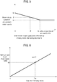
- Each graph of Fig. 5 and Fig. 6 illustrates the principle of calculation in the initial setting.
- Lasing device 20 is placed in an intended working environment and the piping between gas canister 30 and lasing device 20 is installed. After that, the initial setting for calculation of the open time of gas supply valve 10 is carried out.
- step S02 is performed.
- step S02 the laser medium gas retaining in gas circulation path 6, optical resonator 1, and the piping between gas canister 30 and lasing device 20 is completely released.
- current detector 9 detects blower driving current under the normal condition of the gas mixture ratio. The detected current value is stored as driving current Id in the storage mounted on open-time calculator 15.
- Driving current Id is the same as that shown in the graph of Fig. 2C .
- step S03 the lasing device is stopped and maintained in the stop state for predetermined stop time Tc.
- Stop time Tc is counted by stop-time counter 16 and stored in the storage mounted on open-time calculator 15. Stop time Tc is the same as that shown in the graph of Fig. 2C . Stop time Tc can be arbitrarily determined as long as its length is enough for detecting difference in blower driving current (that will be described later).
- step S04 After having stop time Tc, the lasing device is turned on in step S04.
- current detector 9 detects the blower driving current when blower 4 is controlled at a constant speed.
- the detected current value is stored as driving current Ic in the storage mounted on open-time calculator 15.
- Driving current Ic is the same as that shown in the graph of Fig. 2C .
- step S04 until the gas pressure decreases to level B from level A in response to the start up of the lasing device, gas supply valve 10 is maintained to be closed.
- open-time calculator 15 calculates gradient ⁇ from expression (4) described earlier.
- Gradient ⁇ represents correlation of the blower driving current with the stop time of the lasing device.
- the calculated value is stored in the storage mounted on open-time calculator 15.
- step S06 the lasing device is stopped and maintained in the stop state for predetermined stop time Te.
- Stop time Te is counted by stop-time counter 16 and stored in the storage mounted on open-time calculator 15.
- the lasing device After having stop time Te, the lasing device is turned on in step S07.
- the lasing device is operated on the sequence shown in Fig. 3 .
- Open time tf of the gas supply valve in the sequence has a predetermined value, and it is stored in the storage mounted on open-time calculator 15.
- Current detector 9 detects the blower driving current when blower 4 is controlled at a constant speed.
- the detected current value is stored as driving current If in the storage mounted on open-time calculator 15.
- Fig. 5 is a graph showing the relations of aforementioned parameters, such as stop time Te, open time tf of gas supply valve 10, and driving current If.
- Open time tf of gas supply valve 10 can be arbitrarily determined. However, excessively long open-time tf allows the laser medium gas retaining in the piping (between gas canister 30 and gas supply valve 10 of the lasing device) to be completely released from the lasing device 20 before blower 4 starts rotating. In that case, open-time calculator 15 cannot perform calculation. Preferably, open time tf should be several seconds.
- open-time calculator 15 calculates blower driving current Ie by expression (7). The calculation is performed under the condition where gas supply valve 10 is maintained to be closed while the gas pressure is decreasing to level B from level A that is the start-up pressure level of the lasing device after having stop time Te. The calculated value of blower driving current Ie is stored in the storage mounted on open-time calculator 15.
- Te and Ie correspond to Tx' and Ix', respectively, in expression (3).
- open-time calculator 15 calculates gradient ⁇ that represents correlation of blower driving current Ie with blower driving current If by expression (6).
- blower driving current Ie is obtained under the condition where gas supply valve 10 is maintained to be closed while the gas pressure is decreasing to level B from level A that is the start-up pressure level of the lasing device after having stop time Te.
- blower driving current If is obtained under the condition where gas supply valve 10 is maintained to be open for time tf while the gas pressure is decreasing to level B from level A.
- the calculated value of gradient ⁇ which corresponds to the gradient of the graph of Fig. 5 , is stored in the storage mounted on open-time calculator 15.
- step S11 the initial setting is completed (step S11).
- Gradient ⁇ represents degree of influence of the open time of gas supply valve 10 on the driving current for blower 4 with respect to stop time T of the lasing device.
- the open time of gas supply valve 10 capable of offering obtained blower driving current Id is the optimum value as open time t of gas supply valve 10.
- the lasing device works on the normal operation procedures shown in the flowchart of Fig. 4 .
- step S12 the device reads stop time T counted by stop-time counter 16.
- open-time calculator 15 calculates open time t (at the start up of the device) of gas supply valve 10 by expression (10).
- step S14 gas supply valve 10 is open for time t during the gas pressure decreases from level A to level B.
- the aforementioned values ⁇ , ⁇ , and ⁇ should be calculated and stored in a table in advance when the followings have been measured in advance: the distance between gas canister 30 and gas supply valve 10, and the leakage quantity of the piping employed therebetween. This eliminates the processes shown in the flowchart of the initial setting shown in Fig. 3 , reducing the time required for installation of the lasing device.
- the mixture ratio of laser medium gas-retaining in the piping between the gas canister and the gas supply valve of the lasing device-can vary if the piping has a tiny pin hole and the gas leaks from the hole.
- the lasing device of the present invention provides laser output with stability in spite of a change in the mixture ratio of laser medium gas due to, for example, the problem above. Further, the structure of the present invention reduces costs by using decreased number of valves and suppresses consumption of laser medium gas. It is therefore useful for the lasing device employing laser medium gas.
Landscapes
- Physics & Mathematics (AREA)
- Electromagnetism (AREA)
- Engineering & Computer Science (AREA)
- Plasma & Fusion (AREA)
- Optics & Photonics (AREA)
- Lasers (AREA)
Claims (5)
- Dispositif d'émission laser fournissant un gaz de milieu laser continûment ou par intermittence à partir de l'extérieur, comprenant :un résonateur optique (1) ;un trajet d'écoulement de gaz (6) relié au résonateur optique (1) ;un dispositif de fourniture de gaz de milieu laser (30) pour fournir un gaz de milieu laser au trajet d'écoulement de gaz (6) ou au résonateur optique (1) par l'intermédiaire d'une vanne de fourniture de gaz (10) ;une pompe de détente de gaz (12) pour détendre le gaz de milieu laser provenant du trajet d'écoulement de gaz (6) du résonateur optique (1) par l'intermédiaire d'un détendeur de gaz (11) ;un détecteur de pression de gaz (13) pour détecter une pression de gaz du gaz de milieu laser dans le trajet d'écoulement de gaz (6) ou dans le résonateur optique (1) ;un contrôleur de pression de gaz (14) pour commander la vanne de fourniture de gaz (10) et le détendeur de gaz (11) en réponse à la pression de gaz détectée par le détecteur de pression de gaz (13) ;un ventilateur (4) disposé dans le trajet d'écoulement de gaz (6) ;un détecteur de courant (9) pour détecter le courant de commande de ventilateur pour le ventilateur (4) ;un compteur de temps d'arrêt (16) pour compter un temps d'arrêt du dispositif d'émission laser ;une mémoire pour mémoriser les informations corrélées du temps d'arrêt avec le courant de commande de ventilateur ; et caractérisé en ce qu'il comprend en outre :un calculateur de temps d'ouverture (15) configuré pour calculer un temps d'ouverture de la vanne de fourniture de gaz (10) au démarrage du dispositif d'émission laser sur la base des informations corrélées du temps d'arrêt avec le courant de commande de ventilateur provenant de la mémoire,dans lequel le dispositif d'émission laser est configuré de sorte que, lorsque ledit dispositif d'émission laser est activé après un état d'arrêt, le contrôleur de pression de gaz (14) est configuré pour- ouvrir le détendeur de gaz (11) afin de détendre le gaz retenu dans le trajet d'écoulement de gaz (6) et le résonateur optique (1) par l'intermédiaire du détendeur de gaz (11), et- ouvrir la vanne de fourniture de gaz (10) pendant le temps d'ouverture de la vanne de fourniture de gaz calculé par le calculateur de temps d'ouverture (15), de sorte que la vanne de fourniture de gaz (10) soit configurée pour laisser entrer le gaz de milieu laser dans la tuyauterie entre le dispositif de fourniture de gaz de milieu laser (30) et la vanne de fourniture de gaz (10) dans le trajet d'écoulement de gaz (6) et dans le résonateur optique (1) qui est détendu, avec le gaz retenu, à travers le détendeur de gaz (11) ouvert par le contrôleur de pression de gaz (14).
- Dispositif d'émission laser selon la revendication 1, dans lequel le compteur de temps d'arrêt (16) est configuré pour compter un premier temps d'arrêt de dispositif et un deuxième temps d'arrêt de dispositif qui sont au moins déterminés par une opération de paramétrage initiale ayant une séquence différente du fonctionnement normal, dans lequel
le compteur de temps d'arrêt est configuré de sorte que, pendant le premier temps d'arrêt de dispositif et le deuxième temps d'arrêt de dispositif, les informations corrélées soient calculées à partir du courant de commande de ventilateur détecté dans un état dans lequel le dispositif d'émission laser commence à fonctionner avec la vanne de fourniture de gaz (10) maintenue fermée et dans un état dans lequel le dispositif d'émission laser commence à fonctionner après que la vanne de fourniture de gaz (10) a été ouverte pendant un temps prédéterminé, respectivement. - Dispositif d'émission laser selon la revendication 1 ou la revendication 2, dans lequel la vanne de fourniture de gaz (10) est reliée au résonateur optique (1).
- Dispositif d'émission laser selon l'une quelconque des revendications 1 à 3, dans lequel le détendeur de gaz (11) est relié au trajet d'écoulement de gaz (6).
- Dispositif d'émission laser selon l'une quelconque des revendications 1 à 4, dans lequel le détecteur de pression de gaz (13) est relié entre le trajet d'écoulement de gaz (6) et le détendeur de gaz (11).
Applications Claiming Priority (2)
| Application Number | Priority Date | Filing Date | Title |
|---|---|---|---|
| JP2012114364 | 2012-05-18 | ||
| PCT/JP2013/001637 WO2013171951A1 (fr) | 2012-05-18 | 2013-03-13 | Dispositif à effet laser |
Publications (3)
| Publication Number | Publication Date |
|---|---|
| EP2852012A1 EP2852012A1 (fr) | 2015-03-25 |
| EP2852012A4 EP2852012A4 (fr) | 2015-11-11 |
| EP2852012B1 true EP2852012B1 (fr) | 2017-02-22 |
Family
ID=49583384
Family Applications (1)
| Application Number | Title | Priority Date | Filing Date |
|---|---|---|---|
| EP13791219.2A Not-in-force EP2852012B1 (fr) | 2012-05-18 | 2013-03-13 | Dispositif à effet laser |
Country Status (5)
| Country | Link |
|---|---|
| US (1) | US8897331B2 (fr) |
| EP (1) | EP2852012B1 (fr) |
| JP (1) | JP5810270B2 (fr) |
| CN (1) | CN103988378B (fr) |
| WO (1) | WO2013171951A1 (fr) |
Families Citing this family (7)
| Publication number | Priority date | Publication date | Assignee | Title |
|---|---|---|---|---|
| JP5877881B2 (ja) * | 2014-07-14 | 2016-03-08 | ファナック株式会社 | ガス圧及びガス消費量を制御可能なガスレーザ発振器 |
| JP2016096319A (ja) | 2014-11-17 | 2016-05-26 | ファナック株式会社 | レーザガスの供給配管の気密性を検査する機能を備えたガスレーザ装置 |
| JP6189883B2 (ja) * | 2015-01-29 | 2017-08-30 | ファナック株式会社 | レーザガスの組成比を判定するガスレーザ装置 |
| CN115362607A (zh) * | 2020-04-06 | 2022-11-18 | 西默有限公司 | 导管系统、辐射源、光刻装置及其方法 |
| JP2024500674A (ja) * | 2020-12-22 | 2024-01-10 | サイマー リミテッド ライアビリティ カンパニー | ガス放電チャンバブロワのエネルギー消費量を低減すること |
| DE102022204308A1 (de) | 2022-05-02 | 2023-11-02 | Trumpf Lasersystems For Semiconductor Manufacturing Gmbh | Indirekt überwachte Laseranlage |
| WO2024047873A1 (fr) * | 2022-09-02 | 2024-03-07 | ファナック株式会社 | Dispositif de commande, système d'oscillateur laser à gaz et procédé de commande |
Family Cites Families (19)
| Publication number | Priority date | Publication date | Assignee | Title |
|---|---|---|---|---|
| JPS60214577A (ja) * | 1984-04-11 | 1985-10-26 | Matsushita Electric Ind Co Ltd | ガスレ−ザ発振装置 |
| JPS61154189A (ja) * | 1984-12-27 | 1986-07-12 | Matsushita Electric Ind Co Ltd | ガスレ−ザ装置 |
| JPH0783147B2 (ja) * | 1986-03-17 | 1995-09-06 | 株式会社アマダ | 気体レ−ザ発振器におけるレ−ザガス注入方法 |
| JPH01128581A (ja) | 1987-11-13 | 1989-05-22 | Toshiba Corp | ガスレーザ装置 |
| JPH0821744B2 (ja) * | 1990-07-23 | 1996-03-04 | 松下電器産業株式会社 | ガスレーザ発振装置 |
| JP3824092B2 (ja) * | 1993-12-24 | 2006-09-20 | 株式会社小松製作所 | エキシマレ−ザ装置のガス補給方法 |
| JP3694359B2 (ja) | 1996-03-27 | 2005-09-14 | 株式会社ダイヘン | ガスレ−ザ発振器 |
| JPH10173274A (ja) | 1996-12-12 | 1998-06-26 | Komatsu Ltd | エキシマレーザ装置 |
| JP2001244525A (ja) | 2000-03-02 | 2001-09-07 | Matsushita Electric Ind Co Ltd | ガスレーザ発振装置 |
| JP3987300B2 (ja) | 2001-04-24 | 2007-10-03 | ファナック株式会社 | ガスレーザ発振器 |
| JP3858654B2 (ja) * | 2001-09-28 | 2006-12-20 | 松下電器産業株式会社 | ガスレーザ発振装置 |
| US7664154B2 (en) | 2004-04-21 | 2010-02-16 | Mitsubishi Electric Corporation | Gas laser oscillator and gas laser beam machine |
| JP4095095B2 (ja) * | 2006-05-30 | 2008-06-04 | 株式会社小松製作所 | エキシマレーザ装置のガス補給方法 |
| JP4146867B2 (ja) * | 2006-06-22 | 2008-09-10 | ファナック株式会社 | ガスレーザ発振器 |
| JP4137972B2 (ja) * | 2006-12-14 | 2008-08-20 | ファナック株式会社 | ガス組成異常判断方法及び放電励起ガスレーザ発振器 |
| JP2010212553A (ja) * | 2009-03-12 | 2010-09-24 | Panasonic Corp | レーザ発振装置およびレーザ加工機 |
| US9379511B2 (en) * | 2009-03-12 | 2016-06-28 | Panasonic Intellectual Property Management Co., Ltd. | Laser oscillator and laser machining apparatus |
| JP4782887B1 (ja) | 2010-04-02 | 2011-09-28 | ファナック株式会社 | ガスレーザ装置 |
| JP4855529B2 (ja) * | 2010-04-05 | 2012-01-18 | ファナック株式会社 | 微小なレーザ出力を安定に制御するレーザ装置 |
-
2013
- 2013-03-13 CN CN201380004221.XA patent/CN103988378B/zh not_active Expired - Fee Related
- 2013-03-13 WO PCT/JP2013/001637 patent/WO2013171951A1/fr not_active Ceased
- 2013-03-13 EP EP13791219.2A patent/EP2852012B1/fr not_active Not-in-force
- 2013-03-13 JP JP2014515467A patent/JP5810270B2/ja not_active Expired - Fee Related
-
2014
- 2014-05-15 US US14/278,146 patent/US8897331B2/en active Active
Non-Patent Citations (1)
| Title |
|---|
| None * |
Also Published As
| Publication number | Publication date |
|---|---|
| US20140247855A1 (en) | 2014-09-04 |
| JPWO2013171951A1 (ja) | 2016-01-07 |
| WO2013171951A1 (fr) | 2013-11-21 |
| JP5810270B2 (ja) | 2015-11-11 |
| EP2852012A1 (fr) | 2015-03-25 |
| US8897331B2 (en) | 2014-11-25 |
| CN103988378A (zh) | 2014-08-13 |
| EP2852012A4 (fr) | 2015-11-11 |
| CN103988378B (zh) | 2017-02-01 |
Similar Documents
| Publication | Publication Date | Title |
|---|---|---|
| EP2852012B1 (fr) | Dispositif à effet laser | |
| JP6328683B2 (ja) | 小型チラーが使用可能なレーザ装置 | |
| AU2019259382B2 (en) | Gas charging device | |
| CN106159648B (zh) | 具备预测产生结露的功能的激光装置 | |
| CN111819406B (zh) | 制冷剂泄漏检测系统及方法 | |
| KR101077422B1 (ko) | 유량 제어 시스템 | |
| EP1816712B1 (fr) | Oscillateur laser à gaz | |
| US20150372441A1 (en) | Gas laser oscillator capable of estimating sealability of gas container | |
| JP2005251855A (ja) | レーザ装置 | |
| JP5927261B2 (ja) | アラームの種類を判別する機能を備えたガスレーザ装置 | |
| JP2017180748A (ja) | 燃料ガス充填装置 | |
| US9899790B2 (en) | Laser apparatus having temperature control function for maintenance work | |
| JP2016096319A (ja) | レーザガスの供給配管の気密性を検査する機能を備えたガスレーザ装置 | |
| EP2778555B1 (fr) | Système de chauffage d'eau chaude, dispositif de commande et procédé de commande | |
| JP2010127374A (ja) | 水素貯蔵システム | |
| US9590380B2 (en) | Laser oscillator provided with blower | |
| US9147994B2 (en) | Gas laser system capable of maintaining laser gas state during power supply cutoff | |
| US9343867B2 (en) | Gas laser system re-activatable without any damage within short time during recovery of power supply | |
| CN104868349B (zh) | 提高启动工序效率的气体激光装置 | |
| CN119248040B (zh) | 温度控制方法以及环境测试系统 | |
| JP7026550B2 (ja) | 熱供給システムの検査方法 | |
| JP6709138B2 (ja) | ガス充填装置 |
Legal Events
| Date | Code | Title | Description |
|---|---|---|---|
| PUAI | Public reference made under article 153(3) epc to a published international application that has entered the european phase |
Free format text: ORIGINAL CODE: 0009012 |
|
| 17P | Request for examination filed |
Effective date: 20140313 |
|
| AK | Designated contracting states |
Kind code of ref document: A1 Designated state(s): AL AT BE BG CH CY CZ DE DK EE ES FI FR GB GR HR HU IE IS IT LI LT LU LV MC MK MT NL NO PL PT RO RS SE SI SK SM TR |
|
| AX | Request for extension of the european patent |
Extension state: BA ME |
|
| DAX | Request for extension of the european patent (deleted) | ||
| RA4 | Supplementary search report drawn up and despatched (corrected) |
Effective date: 20151009 |
|
| RIC1 | Information provided on ipc code assigned before grant |
Ipc: H01S 3/223 20060101ALI20151005BHEP Ipc: H01S 3/10 20060101ALI20151005BHEP Ipc: H01S 3/036 20060101ALI20151005BHEP Ipc: H01S 3/134 20060101AFI20151005BHEP Ipc: H01S 3/104 20060101ALI20151005BHEP |
|
| GRAP | Despatch of communication of intention to grant a patent |
Free format text: ORIGINAL CODE: EPIDOSNIGR1 |
|
| INTG | Intention to grant announced |
Effective date: 20160920 |
|
| GRAS | Grant fee paid |
Free format text: ORIGINAL CODE: EPIDOSNIGR3 |
|
| GRAJ | Information related to disapproval of communication of intention to grant by the applicant or resumption of examination proceedings by the epo deleted |
Free format text: ORIGINAL CODE: EPIDOSDIGR1 |
|
| GRAL | Information related to payment of fee for publishing/printing deleted |
Free format text: ORIGINAL CODE: EPIDOSDIGR3 |
|
| INTC | Intention to grant announced (deleted) | ||
| GRAR | Information related to intention to grant a patent recorded |
Free format text: ORIGINAL CODE: EPIDOSNIGR71 |
|
| GRAA | (expected) grant |
Free format text: ORIGINAL CODE: 0009210 |
|
| INTG | Intention to grant announced |
Effective date: 20170112 |
|
| AK | Designated contracting states |
Kind code of ref document: B1 Designated state(s): AL AT BE BG CH CY CZ DE DK EE ES FI FR GB GR HR HU IE IS IT LI LT LU LV MC MK MT NL NO PL PT RO RS SE SI SK SM TR |
|
| REG | Reference to a national code |
Ref country code: GB Ref legal event code: FG4D |
|
| REG | Reference to a national code |
Ref country code: CH Ref legal event code: EP |
|
| REG | Reference to a national code |
Ref country code: AT Ref legal event code: REF Ref document number: 869944 Country of ref document: AT Kind code of ref document: T Effective date: 20170315 |
|
| REG | Reference to a national code |
Ref country code: IE Ref legal event code: FG4D |
|
| REG | Reference to a national code |
Ref country code: DE Ref legal event code: R096 Ref document number: 602013017732 Country of ref document: DE |
|
| REG | Reference to a national code |
Ref country code: LT Ref legal event code: MG4D |
|
| REG | Reference to a national code |
Ref country code: NL Ref legal event code: MP Effective date: 20170222 |
|
| REG | Reference to a national code |
Ref country code: AT Ref legal event code: MK05 Ref document number: 869944 Country of ref document: AT Kind code of ref document: T Effective date: 20170222 |
|
| PG25 | Lapsed in a contracting state [announced via postgrant information from national office to epo] |
Ref country code: GR Free format text: LAPSE BECAUSE OF FAILURE TO SUBMIT A TRANSLATION OF THE DESCRIPTION OR TO PAY THE FEE WITHIN THE PRESCRIBED TIME-LIMIT Effective date: 20170523 Ref country code: NO Free format text: LAPSE BECAUSE OF FAILURE TO SUBMIT A TRANSLATION OF THE DESCRIPTION OR TO PAY THE FEE WITHIN THE PRESCRIBED TIME-LIMIT Effective date: 20170522 Ref country code: FI Free format text: LAPSE BECAUSE OF FAILURE TO SUBMIT A TRANSLATION OF THE DESCRIPTION OR TO PAY THE FEE WITHIN THE PRESCRIBED TIME-LIMIT Effective date: 20170222 Ref country code: LT Free format text: LAPSE BECAUSE OF FAILURE TO SUBMIT A TRANSLATION OF THE DESCRIPTION OR TO PAY THE FEE WITHIN THE PRESCRIBED TIME-LIMIT Effective date: 20170222 Ref country code: HR Free format text: LAPSE BECAUSE OF FAILURE TO SUBMIT A TRANSLATION OF THE DESCRIPTION OR TO PAY THE FEE WITHIN THE PRESCRIBED TIME-LIMIT Effective date: 20170222 |
|
| PG25 | Lapsed in a contracting state [announced via postgrant information from national office to epo] |
Ref country code: RS Free format text: LAPSE BECAUSE OF FAILURE TO SUBMIT A TRANSLATION OF THE DESCRIPTION OR TO PAY THE FEE WITHIN THE PRESCRIBED TIME-LIMIT Effective date: 20170222 Ref country code: BG Free format text: LAPSE BECAUSE OF FAILURE TO SUBMIT A TRANSLATION OF THE DESCRIPTION OR TO PAY THE FEE WITHIN THE PRESCRIBED TIME-LIMIT Effective date: 20170522 Ref country code: AT Free format text: LAPSE BECAUSE OF FAILURE TO SUBMIT A TRANSLATION OF THE DESCRIPTION OR TO PAY THE FEE WITHIN THE PRESCRIBED TIME-LIMIT Effective date: 20170222 Ref country code: SE Free format text: LAPSE BECAUSE OF FAILURE TO SUBMIT A TRANSLATION OF THE DESCRIPTION OR TO PAY THE FEE WITHIN THE PRESCRIBED TIME-LIMIT Effective date: 20170222 Ref country code: ES Free format text: LAPSE BECAUSE OF FAILURE TO SUBMIT A TRANSLATION OF THE DESCRIPTION OR TO PAY THE FEE WITHIN THE PRESCRIBED TIME-LIMIT Effective date: 20170222 Ref country code: NL Free format text: LAPSE BECAUSE OF FAILURE TO SUBMIT A TRANSLATION OF THE DESCRIPTION OR TO PAY THE FEE WITHIN THE PRESCRIBED TIME-LIMIT Effective date: 20170222 Ref country code: PT Free format text: LAPSE BECAUSE OF FAILURE TO SUBMIT A TRANSLATION OF THE DESCRIPTION OR TO PAY THE FEE WITHIN THE PRESCRIBED TIME-LIMIT Effective date: 20170622 Ref country code: LV Free format text: LAPSE BECAUSE OF FAILURE TO SUBMIT A TRANSLATION OF THE DESCRIPTION OR TO PAY THE FEE WITHIN THE PRESCRIBED TIME-LIMIT Effective date: 20170222 |
|
| PG25 | Lapsed in a contracting state [announced via postgrant information from national office to epo] |
Ref country code: IT Free format text: LAPSE BECAUSE OF FAILURE TO SUBMIT A TRANSLATION OF THE DESCRIPTION OR TO PAY THE FEE WITHIN THE PRESCRIBED TIME-LIMIT Effective date: 20170222 Ref country code: EE Free format text: LAPSE BECAUSE OF FAILURE TO SUBMIT A TRANSLATION OF THE DESCRIPTION OR TO PAY THE FEE WITHIN THE PRESCRIBED TIME-LIMIT Effective date: 20170222 Ref country code: RO Free format text: LAPSE BECAUSE OF FAILURE TO SUBMIT A TRANSLATION OF THE DESCRIPTION OR TO PAY THE FEE WITHIN THE PRESCRIBED TIME-LIMIT Effective date: 20170222 Ref country code: SK Free format text: LAPSE BECAUSE OF FAILURE TO SUBMIT A TRANSLATION OF THE DESCRIPTION OR TO PAY THE FEE WITHIN THE PRESCRIBED TIME-LIMIT Effective date: 20170222 Ref country code: CZ Free format text: LAPSE BECAUSE OF FAILURE TO SUBMIT A TRANSLATION OF THE DESCRIPTION OR TO PAY THE FEE WITHIN THE PRESCRIBED TIME-LIMIT Effective date: 20170222 |
|
| REG | Reference to a national code |
Ref country code: CH Ref legal event code: PL |
|
| REG | Reference to a national code |
Ref country code: DE Ref legal event code: R097 Ref document number: 602013017732 Country of ref document: DE |
|
| PG25 | Lapsed in a contracting state [announced via postgrant information from national office to epo] |
Ref country code: MC Free format text: LAPSE BECAUSE OF FAILURE TO SUBMIT A TRANSLATION OF THE DESCRIPTION OR TO PAY THE FEE WITHIN THE PRESCRIBED TIME-LIMIT Effective date: 20170222 Ref country code: SM Free format text: LAPSE BECAUSE OF FAILURE TO SUBMIT A TRANSLATION OF THE DESCRIPTION OR TO PAY THE FEE WITHIN THE PRESCRIBED TIME-LIMIT Effective date: 20170222 Ref country code: DK Free format text: LAPSE BECAUSE OF FAILURE TO SUBMIT A TRANSLATION OF THE DESCRIPTION OR TO PAY THE FEE WITHIN THE PRESCRIBED TIME-LIMIT Effective date: 20170222 Ref country code: PL Free format text: LAPSE BECAUSE OF FAILURE TO SUBMIT A TRANSLATION OF THE DESCRIPTION OR TO PAY THE FEE WITHIN THE PRESCRIBED TIME-LIMIT Effective date: 20170222 |
|
| REG | Reference to a national code |
Ref country code: IE Ref legal event code: MM4A |
|
| PLBE | No opposition filed within time limit |
Free format text: ORIGINAL CODE: 0009261 |
|
| REG | Reference to a national code |
Ref country code: FR Ref legal event code: ST Effective date: 20171130 |
|
| STAA | Information on the status of an ep patent application or granted ep patent |
Free format text: STATUS: NO OPPOSITION FILED WITHIN TIME LIMIT |
|
| GBPC | Gb: european patent ceased through non-payment of renewal fee |
Effective date: 20170522 |
|
| 26N | No opposition filed |
Effective date: 20171123 |
|
| PG25 | Lapsed in a contracting state [announced via postgrant information from national office to epo] |
Ref country code: LU Free format text: LAPSE BECAUSE OF NON-PAYMENT OF DUE FEES Effective date: 20170313 Ref country code: FR Free format text: LAPSE BECAUSE OF NON-PAYMENT OF DUE FEES Effective date: 20170424 |
|
| PG25 | Lapsed in a contracting state [announced via postgrant information from national office to epo] |
Ref country code: IE Free format text: LAPSE BECAUSE OF NON-PAYMENT OF DUE FEES Effective date: 20170313 Ref country code: LI Free format text: LAPSE BECAUSE OF NON-PAYMENT OF DUE FEES Effective date: 20170331 Ref country code: CH Free format text: LAPSE BECAUSE OF NON-PAYMENT OF DUE FEES Effective date: 20170331 Ref country code: SI Free format text: LAPSE BECAUSE OF FAILURE TO SUBMIT A TRANSLATION OF THE DESCRIPTION OR TO PAY THE FEE WITHIN THE PRESCRIBED TIME-LIMIT Effective date: 20170222 |
|
| REG | Reference to a national code |
Ref country code: BE Ref legal event code: MM Effective date: 20170331 |
|
| PG25 | Lapsed in a contracting state [announced via postgrant information from national office to epo] |
Ref country code: GB Free format text: LAPSE BECAUSE OF NON-PAYMENT OF DUE FEES Effective date: 20170522 |
|
| PG25 | Lapsed in a contracting state [announced via postgrant information from national office to epo] |
Ref country code: BE Free format text: LAPSE BECAUSE OF NON-PAYMENT OF DUE FEES Effective date: 20170331 |
|
| PG25 | Lapsed in a contracting state [announced via postgrant information from national office to epo] |
Ref country code: MT Free format text: LAPSE BECAUSE OF NON-PAYMENT OF DUE FEES Effective date: 20170313 |
|
| PG25 | Lapsed in a contracting state [announced via postgrant information from national office to epo] |
Ref country code: HU Free format text: LAPSE BECAUSE OF FAILURE TO SUBMIT A TRANSLATION OF THE DESCRIPTION OR TO PAY THE FEE WITHIN THE PRESCRIBED TIME-LIMIT; INVALID AB INITIO Effective date: 20130313 |
|
| PG25 | Lapsed in a contracting state [announced via postgrant information from national office to epo] |
Ref country code: CY Free format text: LAPSE BECAUSE OF FAILURE TO SUBMIT A TRANSLATION OF THE DESCRIPTION OR TO PAY THE FEE WITHIN THE PRESCRIBED TIME-LIMIT Effective date: 20170222 |
|
| PG25 | Lapsed in a contracting state [announced via postgrant information from national office to epo] |
Ref country code: MK Free format text: LAPSE BECAUSE OF FAILURE TO SUBMIT A TRANSLATION OF THE DESCRIPTION OR TO PAY THE FEE WITHIN THE PRESCRIBED TIME-LIMIT Effective date: 20170222 |
|
| PG25 | Lapsed in a contracting state [announced via postgrant information from national office to epo] |
Ref country code: TR Free format text: LAPSE BECAUSE OF FAILURE TO SUBMIT A TRANSLATION OF THE DESCRIPTION OR TO PAY THE FEE WITHIN THE PRESCRIBED TIME-LIMIT Effective date: 20170222 |
|
| PG25 | Lapsed in a contracting state [announced via postgrant information from national office to epo] |
Ref country code: AL Free format text: LAPSE BECAUSE OF FAILURE TO SUBMIT A TRANSLATION OF THE DESCRIPTION OR TO PAY THE FEE WITHIN THE PRESCRIBED TIME-LIMIT Effective date: 20170222 Ref country code: IS Free format text: LAPSE BECAUSE OF FAILURE TO SUBMIT A TRANSLATION OF THE DESCRIPTION OR TO PAY THE FEE WITHIN THE PRESCRIBED TIME-LIMIT Effective date: 20170622 |
|
| PGFP | Annual fee paid to national office [announced via postgrant information from national office to epo] |
Ref country code: DE Payment date: 20220609 Year of fee payment: 11 |
|
| REG | Reference to a national code |
Ref country code: DE Ref legal event code: R119 Ref document number: 602013017732 Country of ref document: DE |
|
| PG25 | Lapsed in a contracting state [announced via postgrant information from national office to epo] |
Ref country code: DE Free format text: LAPSE BECAUSE OF NON-PAYMENT OF DUE FEES Effective date: 20241001 |
|
| PG25 | Lapsed in a contracting state [announced via postgrant information from national office to epo] |
Ref country code: DE Free format text: LAPSE BECAUSE OF NON-PAYMENT OF DUE FEES Effective date: 20241001 |